EP4549707A1 - Engine - Google Patents
Engine Download PDFInfo
- Publication number
- EP4549707A1 EP4549707A1 EP23871602.1A EP23871602A EP4549707A1 EP 4549707 A1 EP4549707 A1 EP 4549707A1 EP 23871602 A EP23871602 A EP 23871602A EP 4549707 A1 EP4549707 A1 EP 4549707A1
- Authority
- EP
- European Patent Office
- Prior art keywords
- camshaft
- hole
- engine
- oil
- chamber
- Prior art date
- Legal status (The legal status is an assumption and is not a legal conclusion. Google has not performed a legal analysis and makes no representation as to the accuracy of the status listed.)
- Pending
Links
Images







Classifications
-
- F—MECHANICAL ENGINEERING; LIGHTING; HEATING; WEAPONS; BLASTING
- F01—MACHINES OR ENGINES IN GENERAL; ENGINE PLANTS IN GENERAL; STEAM ENGINES
- F01M—LUBRICATING OF MACHINES OR ENGINES IN GENERAL; LUBRICATING INTERNAL COMBUSTION ENGINES; CRANKCASE VENTILATING
- F01M9/00—Lubrication means having pertinent characteristics not provided for in, or of interest apart from, groups F01M1/00 - F01M7/00
- F01M9/10—Lubrication of valve gear or auxiliaries
-
- F—MECHANICAL ENGINEERING; LIGHTING; HEATING; WEAPONS; BLASTING
- F01—MACHINES OR ENGINES IN GENERAL; ENGINE PLANTS IN GENERAL; STEAM ENGINES
- F01M—LUBRICATING OF MACHINES OR ENGINES IN GENERAL; LUBRICATING INTERNAL COMBUSTION ENGINES; CRANKCASE VENTILATING
- F01M1/00—Pressure lubrication
- F01M1/08—Lubricating systems characterised by the provision therein of lubricant jetting means
-
- F—MECHANICAL ENGINEERING; LIGHTING; HEATING; WEAPONS; BLASTING
- F01—MACHINES OR ENGINES IN GENERAL; ENGINE PLANTS IN GENERAL; STEAM ENGINES
- F01M—LUBRICATING OF MACHINES OR ENGINES IN GENERAL; LUBRICATING INTERNAL COMBUSTION ENGINES; CRANKCASE VENTILATING
- F01M11/00—Component parts, details or accessories, not provided for in, or of interest apart from, groups F01M1/00 - F01M9/00
- F01M11/02—Arrangements of lubricant conduits
-
- F—MECHANICAL ENGINEERING; LIGHTING; HEATING; WEAPONS; BLASTING
- F01—MACHINES OR ENGINES IN GENERAL; ENGINE PLANTS IN GENERAL; STEAM ENGINES
- F01M—LUBRICATING OF MACHINES OR ENGINES IN GENERAL; LUBRICATING INTERNAL COMBUSTION ENGINES; CRANKCASE VENTILATING
- F01M9/00—Lubrication means having pertinent characteristics not provided for in, or of interest apart from, groups F01M1/00 - F01M7/00
- F01M9/10—Lubrication of valve gear or auxiliaries
- F01M9/101—Lubrication of valve gear or auxiliaries of cam surfaces
-
- F—MECHANICAL ENGINEERING; LIGHTING; HEATING; WEAPONS; BLASTING
- F02—COMBUSTION ENGINES; HOT-GAS OR COMBUSTION-PRODUCT ENGINE PLANTS
- F02F—CYLINDERS, PISTONS OR CASINGS, FOR COMBUSTION ENGINES; ARRANGEMENTS OF SEALINGS IN COMBUSTION ENGINES
- F02F1/00—Cylinders; Cylinder heads
- F02F1/18—Other cylinders
- F02F1/20—Other cylinders characterised by constructional features providing for lubrication
Definitions
- the present invention relates to an engine, and specifically to a shaft-less engine in which lubrication of a cam of a camshaft is not hindered in a case where a cylinder block is shared by engines having different specifications and distinguished by presence or absence of a predetermined rotation shaft.
- Patent Document 1 Japanese Patent Application Laid-open No. 2005-83336 (see Fig. 1 )
- An object of the present invention is to provide a shaft-less engine in which lubrication of a cam of a camshaft is not hindered in a case where a cylinder block is shared by engines having different specifications and distinguished by presence or absence of a predetermined rotation shaft.
- a main configuration of the present invention is as follows.
- An engine includes a cylinder block front wall (2a), a camshaft chamber front wall (2b) as exemplified in Fig. 2 , and a camshaft chamber (2c) provided on a rear side of the camshaft chamber front wall (2b) as exemplified in Fig. 3 with an extending direction of a crankshaft (1) defined as a front-rear direction, one side in the front-rear direction defined as a front side, and another side in the front-rear direction defined as the rear side as exemplified in Fig. 1 , in which a camshaft (5) is housed in the camshaft chamber (2c),
- the present invention has the following effects.
- a shaft-equipped engine can be manufactured. Therefore, the cylinder block (2) can be shared with a shaft-equipped engine.
- Figs. 1 to 9 are diagrams for describing a shaft-less engine according to an embodiment of the present invention
- Figs. 10 to 12 show a shaft-equipped engine that shares a cylinder block with the shaft-less engine.
- a common rail type vertical straight multi-cylinder (three-cylinder) diesel engine will be described.
- an extending direction of a crankshaft is a front-rear direction
- one side in the front-rear direction is a front side
- another side is a rear side
- a width direction of the engine orthogonal to the front-rear direction is a lateral direction.
- the shaft-less engine shown in Fig. 5 includes a cylinder block (2), a cylinder head (14) assembled to an upper portion of the cylinder block (2), a cylinder head cover (15) assembled to an upper portion of the cylinder head (14), a timing transmission case (10) assembled to a front portion of the cylinder block (2), an engine cooling fan (16) disposed on a front side of the timing transmission case (10), a flywheel (17) disposed at a rear portion of the cylinder block (2), and an oil pan (18) assembled to a lower portion of the cylinder block (2).
- a crankcase (2h) is configured in a lower portion of the cylinder block (2).
- crankcase (2h) houses a crankshaft (1).
- the engine includes an intake device, a fuel supply device, and an exhaust device.
- the intake device includes an intake manifold (19) assembled to one lateral side of the cylinder head (14). Air in the intake manifold (19) is sucked into each cylinder (not shown) from an intake port (not shown) by opening an intake valve (not shown).
- the exhaust device includes an exhaust manifold (20) assembled to another lateral side of the cylinder head (14). Exhaust of each cylinder is discharged from an exhaust port (not shown) to an exhaust manifold (20) by opening an exhaust valve (not shown).
- the intake valve and the exhaust valve are driven to open and close by a cam (not shown) of a valve camshaft (21) shown in Fig. 4 .
- the fuel supply device includes a fuel pressure-feed pump (4) and a fuel injection device (3).
- a fuel injection device (3) is a common rail type fuel injection device (3a), and includes a common rail (3b) and a fuel injector (3c) that injects liquid fuel accumulated in the common rail (3b) into each cylinder.
- the fuel pressure-feed pump (4) that supplies the liquid fuel to the common rail (3b) is a fuel supply pump (4a).
- An electromagnetic valve of the fuel injector (3c) shown in Fig. 5 is opened for a predetermined period at a predetermined timing by control of an engine ECU (22) on the basis of detection of an accelerator position and an engine load, and a predetermined amount of the liquid fuel is injected from the fuel injector (3c) into each cylinder at a predetermined timing.
- the engine ECU (22) is attached to an intake-side side surface of the cylinder block (2).
- the ECU is an abbreviation of an electronic control unit, and a microcomputer is used.
- the engine ECU (22) functions as a control device (6) of the engine.
- the timing of opening and closing the electromagnetic valve of the fuel injector (3c) shown in Fig. 5 is set on the basis of a crank angle of the crankshaft (1) and a cam position of the valve camshaft (21).
- the accelerator position is detected by an accelerator position sensor (not shown).
- the engine load is calculated by the engine ECU (22) by comparison of the accelerator position with an engine speed.
- the engine speed and the crank angle of the crankshaft (1) are detected by an electromagnetic pickup (not shown) that detects unevenness of an outer periphery of a crankshaft disk (not shown) attached to the crankshaft (1), and the cam position is detected by a cam position sensor (not shown) that detects unevenness of an outer periphery of a camshaft disk (not shown) attached to the valve camshaft (21) shown in Fig. 4 .
- the engine includes a cylinder block front wall (2a), a camshaft chamber front wall (2b), and a camshaft chamber (2c) provided on a rear side of the camshaft chamber front wall (2b) as shown in Fig. 3 , and a camshaft (5) is housed in the camshaft chamber (2c).
- the camshaft (5) is a pump drive camshaft (5) that drives the fuel pressure-feed pump (4).
- the camshaft chamber front wall (2b) includes a front bearing hole (2d) of the camshaft (5) and a front hole (2e) disposed below the front bearing hole (2d), and a camshaft chamber rear wall (2f) includes a rear hole (2g) concentric with the front hole (2e).
- a shaft-equipped engine can be manufactured. Therefore, the cylinder block (2) can be shared between the shaft-less engine and the shaft-equipped engine.
- the cylinder block front wall (2a) includes an oil supply passage (8) in which a passage outlet (8a) is formed on an inner peripheral surface of the front hole (2e), a fitting component (9) that covers the passage outlet (8a) of the oil supply passage (8) is fitted in the front hole (2e) of the camshaft chamber front wall (2b), and as shown in Fig. 3 , the fitting component (9) includes a camshaft oil jet hole (9a) that injects engine oil (7) from the oil supply passage (8) to the camshaft (5).
- the camshaft (5) includes the cam (5a) that drives the fuel pressure-feed pump (4) inserted into the camshaft chamber (2c).
- the predetermined rotation shaft (R) is a PTO shaft (30).
- PTO is an abbreviation of power take off, and refers to taking out a work output from an engine.
- the predetermined rotation shaft (R) may be a governor shaft or a balancer shaft other than the PTO shaft (30).
- the camshaft chamber front wall (2b) protrudes laterally from the cylinder block front wall (2a), and as shown in Fig. 2 , the camshaft chamber (2c) is formed laterally of the cylinder block (2).
- the camshaft oil jet hole (9a) is provided in an inner diameter portion (9b) along an inner diameter of the fitting component (9).
- a degree of freedom in setting an arrangement and an orientation of the camshaft oil jet hole (9a) is high, and an injection direction and an injection position of the engine oil (7) from the camshaft oil jet hole (9a) can be optimized.
- the engine includes a camshaft input gear (12) of the camshaft (5) on the front side of the camshaft chamber front wall (2b), and as shown in Figs. 3 and 4 , the fitting component (9) includes a gear oil jet hole (9c) that injects the engine oil (7) from the oil supply passage (8) to the camshaft input gear (12).
- the camshaft oil jet hole (9a) and the gear oil jet hole (9c) are provided in the inner diameter portion (9b) along the inner diameter of the fitting component (9).
- a degree of freedom in setting an arrangement and an orientation of the camshaft oil jet hole (9a) and the gear oil jet hole (9c) is high, and an injection direction and an injection position of the engine oil (7) from the camshaft oil jet hole (9a) and the gear oil jet hole (9c) can be optimized.
- the fitting component (9) includes a cylindrical collar (9d) fitted in the front hole (2e), the disk-shaped inner diameter portion (9b) along an inner diameter of the collar (9d), a raised portion (9e) extending from an inner peripheral surface of the collar (9d) along front and back surfaces of the inner diameter portion (9b), an oil introduction passage (9f) provided in the raised portion (9e) and communicating with the oil supply passage (8) shown in Fig. 2 , and the camshaft oil jet hole (9a) and the gear oil jet hole (9c) led out from the oil introduction passage (9f) as shown in Fig. 3 .
- the cam (5a) of the camshaft (5) includes three cam noses at 120° intervals in a circumferential direction of the camshaft (5).
- the fuel supply pump (4a) pumps the liquid fuel to the common rail (3b) at every crank angle of 720° during one combustion cycle at a crank angle of 240°.
- the camshaft (5) is borne by a camshaft front bearing (5b) internally fitted into the front bearing hole (2d) and a camshaft rear bearing (5c) internally fitted into a rear bearing hole (2k) concentric with the camshaft front bearing (5b), and is installed in the camshaft chamber (2c).
- the rear bearing hole (2k) is formed in the camshaft chamber rear wall (2f), and is closed by a camshaft rear plug (2ka).
- the rear hole (2g) is closed by a rear hole plug (2ga).
- the camshaft chamber (2c) includes upper and lower oil mist introduction ports (2n) and (2p) communicating with the inside of the crankcase (2h) and an oil mist outlet port (2q) communicating with the inside of the timing transmission case (10) shown in Fig. 4 , oil mist of the engine oil (7) splashed up to the crankshaft (1) in the crankcase (2h) is introduced into the camshaft chamber (2c) from the upper and lower oil mist introduction ports (2n) and (2p) shown in Fig.
- the cam (5a) of the pump drive camshaft (5) is lubricated, the oil mist in the camshaft chamber (2c) is led out into the timing transmission case (10) from the oil mist outlet port (2q) shown in Fig. 4 , and a timing transmission gear train (11) such as the camshaft input gear (12) is lubricated.
- the timing transmission case (10) covers the cylinder block front wall (2a) and the camshaft chamber front wall (2b) from the front side, and the timing transmission gear train (11) housed in the timing transmission case (10) includes a crank gear (1a) attached to a crankshaft (1), an idle gear (13) meshed with the crank gear (1a), and the camshaft input gear (12) and a valve camshaft input gear (21a) that are meshed with the idle gear (13).
- Gear ratios of the crank gear (1a) to the camshaft input gear (12) and the valve camshaft input gear (21a) of the pump drive camshaft (5) are both two, and the pump drive camshaft (5) and the valve camshaft (21) make one rotation while the crankshaft (1) makes two rotations.
- the configuration of a shaft-equipped engine that shares the cylinder block (2) with a shaft-less engine without the predetermined rotation shaft (R) is as follows.
- the engine includes the PTO shaft (30) as the predetermined rotation shaft (R).
- the PTO shaft (30) includes a PTO shaft input gear (30a), a journal portion (30b), and a slit-shaped PTO shaft output unit (30c) at a rear end.
- the PTO shaft (30) is borne by the front bearing (30d) fitted in the front hole (2e) and the rear bearing (30e) fitted in the rear hole (2g), and is installed in a lower portion of the camshaft chamber (2c).
- PTO output from the PTO shaft (30) is performed by extracting the rear hole plug (2ga) from the rear hole (2g) and connecting an input unit of a work device such as a hydraulic pump to the PTO shaft output unit (30c).
- the predetermined rotation shaft (R) may be a governor shaft or a balancer shaft other than the PTO shaft (30).
Landscapes
- Engineering & Computer Science (AREA)
- Mechanical Engineering (AREA)
- General Engineering & Computer Science (AREA)
- Lubrication Of Internal Combustion Engines (AREA)
- Cylinder Crankcases Of Internal Combustion Engines (AREA)
Abstract
Provided is a shaft-less engine in which lubrication of a cam (5a) of a camshaft (5) is not hindered in a case where a cylinder block (2) is shared by engines having different specifications and distinguished by presence or absence of a predetermined rotation shaft (R). A camshaft chamber front wall (2b) includes a front bearing hole (2d) of the camshaft (5) and a front hole (2e) disposed below the front bearing hole (2d), a camshaft chamber rear wall (2f) includes a rear hole (2g) concentric with the front hole (2e), a cylinder block front wall (2a) includes an oil supply passage (8) in which a passage outlet (8a) is formed on an inner peripheral surface of the front hole (2e), a fitting component (9) that covers the passage outlet (8a) of the oil supply passage (8) is internally fitted into the front hole (2e) of the camshaft chamber front wall (2b), and the fitting component (9) includes a camshaft oil jet hole (9a) that injects engine oil (7) from the oil supply passage (8) to the camshaft (5).
Description
- The present invention relates to an engine, and specifically to a shaft-less engine in which lubrication of a cam of a camshaft is not hindered in a case where a cylinder block is shared by engines having different specifications and distinguished by presence or absence of a predetermined rotation shaft.
- Conventionally, there is an engine in which a predetermined rotation shaft (governor shaft) is installed in a camshaft chamber (see, for example, Patent Document 1).
- It is conceivable to manufacture a shaft-less engine without a predetermined rotation shaft (governor shaft) while sharing the same cylinder block as the shaft-equipped engine having the predetermined rotation shaft (governor shaft).
- Patent Document 1:
Japanese Patent Application Laid-open No. 2005-83336 Fig. 1 ) - In a shaft-less engine, lubrication of the cam of the camshaft could be hindered.
- In a case where a shaft-less engine is manufactured as described above, engine oil cannot be splashed up by the predetermined rotation shaft (governor shaft). Thus, oil mist in a camshaft chamber is insufficient, and the lubrication of the cam of the camshaft could be hindered.
- An object of the present invention is to provide a shaft-less engine in which lubrication of a cam of a camshaft is not hindered in a case where a cylinder block is shared by engines having different specifications and distinguished by presence or absence of a predetermined rotation shaft.
- A main configuration of the present invention is as follows.
- An engine includes a cylinder block front wall (2a), a camshaft chamber front wall (2b) as exemplified in
Fig. 2 , and a camshaft chamber (2c) provided on a rear side of the camshaft chamber front wall (2b) as exemplified inFig. 3 with an extending direction of a crankshaft (1) defined as a front-rear direction, one side in the front-rear direction defined as a front side, and another side in the front-rear direction defined as the rear side as exemplified inFig. 1 , in which a camshaft (5) is housed in the camshaft chamber (2c), - the camshaft chamber front wall (2b) includes a front bearing hole (2d) of the camshaft (5) and a front hole (2e) disposed below the front bearing hole (2d) as exemplified in
Fig. 3 , and a camshaft chamber rear wall (2f) includes a rear hole (2g) concentric with the front hole (2e), - the cylinder block front wall (2a) includes an oil supply passage (8) in which a passage outlet (8a) is formed on an inner peripheral surface of the front hole (2e) as exemplified in
Fig. 2 , a fitting component (9) that covers the passage outlet (8a) of the oil supply passage (8) is fitted in the front hole (2e) of the camshaft chamber front wall (2b), and the fitting component (9) includes a camshaft oil jet hole (9a) that injects engine oil (7) from the oil supply passage (8) to the camshaft (5) as exemplified inFig. 3 . - The present invention has the following effects.
- Even in a shaft-less engine, lubrication of a cam (5a) of the camshaft (5) is not hindered in a case where a cylinder block (2) is shared by engines having different specifications and distinguished by presence or absence of a predetermined rotation shaft (R).
- As exemplified in
Fig. 10 , by bridging a predetermined rotation shaft (R) below the camshaft (5) via front and rear bearings (30d) and (30e) internally fitted into the front hole (2e) and the rear hole (2g) without a fitting component (9), a shaft-equipped engine can be manufactured. Therefore, the cylinder block (2) can be shared with a shaft-equipped engine. - Then, as exemplified in
Fig. 3 , since the engine oil (7) is injected from the oil jet hole (9a) to the camshaft (5), the lubrication of a cam (5a) of the camshaft (5) is not hindered although the engine is a shaft-less engine without the predetermined rotation shaft (R) (exemplified inFig. 10 ) that splashes the engine oil (7) by rotation. - In this manner, in even a shaft-less engine, the lubrication of the cam (5a) of the camshaft (5) is not hindered in a case where the cylinder block (2) is shared by engines having different specifications and distinguished by the presence or absence of the predetermined rotation shaft (R).
-
-
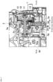
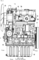
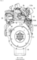
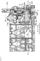
Fig. 1 is a partially cutaway right side view of a main part of a shaft-less engine according to an embodiment of the present invention. -
Fig. 2 is a sectional view taken along line II-II inFig. 1 . -
Fig. 3 is a sectional view taken along line III-III inFig. 2 . -
Fig. 4 is a sectional view taken along line IV-IV inFig. 1 . -
Fig. 5 is a right side view of the engine inFig. 1 . -
Fig. 6 is a left side view of the engine inFig. 1 . -
Fig. 7 is a front view of the engine inFig. 1 . -
Fig. 8 is a rear view of the engine inFig. 1 . -
Fig. 9 is a plan view of the engine inFig. 1 . -
Fig. 10 is a partially cutaway right side view of a main part of a shaft-equipped engine that shares a cylinder block with the engine inFig. 1 . -
Fig. 11 is a sectional view taken along line XI-XI inFig. 10 . -
Fig. 12 is a sectional view taken along line XII-XII inFig. 10 . -
Figs. 1 to 9 are diagrams for describing a shaft-less engine according to an embodiment of the present invention, andFigs. 10 to 12 show a shaft-equipped engine that shares a cylinder block with the shaft-less engine. In this embodiment, a common rail type vertical straight multi-cylinder (three-cylinder) diesel engine will be described. - As shown in
Fig. 1 , an extending direction of a crankshaft is a front-rear direction, one side in the front-rear direction is a front side, another side is a rear side, and as shown inFig. 2 , a width direction of the engine orthogonal to the front-rear direction is a lateral direction. - The shaft-less engine shown in
Fig. 5 includes a cylinder block (2), a cylinder head (14) assembled to an upper portion of the cylinder block (2), a cylinder head cover (15) assembled to an upper portion of the cylinder head (14), a timing transmission case (10) assembled to a front portion of the cylinder block (2), an engine cooling fan (16) disposed on a front side of the timing transmission case (10), a flywheel (17) disposed at a rear portion of the cylinder block (2), and an oil pan (18) assembled to a lower portion of the cylinder block (2). A crankcase (2h) is configured in a lower portion of the cylinder block (2). - The crankcase (2h) houses a crankshaft (1).
- The engine includes an intake device, a fuel supply device, and an exhaust device.
- As shown in
Fig. 5 , the intake device includes an intake manifold (19) assembled to one lateral side of the cylinder head (14). Air in the intake manifold (19) is sucked into each cylinder (not shown) from an intake port (not shown) by opening an intake valve (not shown). - As shown in
Fig. 6 , the exhaust device includes an exhaust manifold (20) assembled to another lateral side of the cylinder head (14). Exhaust of each cylinder is discharged from an exhaust port (not shown) to an exhaust manifold (20) by opening an exhaust valve (not shown). - The intake valve and the exhaust valve are driven to open and close by a cam (not shown) of a valve camshaft (21) shown in
Fig. 4 . - As shown in
Fig. 5 , the fuel supply device includes a fuel pressure-feed pump (4) and a fuel injection device (3). - A fuel injection device (3) is a common rail type fuel injection device (3a), and includes a common rail (3b) and a fuel injector (3c) that injects liquid fuel accumulated in the common rail (3b) into each cylinder.
- The fuel pressure-feed pump (4) that supplies the liquid fuel to the common rail (3b) is a fuel supply pump (4a).
- An electromagnetic valve of the fuel injector (3c) shown in
Fig. 5 is opened for a predetermined period at a predetermined timing by control of an engine ECU (22) on the basis of detection of an accelerator position and an engine load, and a predetermined amount of the liquid fuel is injected from the fuel injector (3c) into each cylinder at a predetermined timing. The engine ECU (22) is attached to an intake-side side surface of the cylinder block (2). - The ECU is an abbreviation of an electronic control unit, and a microcomputer is used.
- The engine ECU (22) functions as a control device (6) of the engine.
- The timing of opening and closing the electromagnetic valve of the fuel injector (3c) shown in
Fig. 5 is set on the basis of a crank angle of the crankshaft (1) and a cam position of the valve camshaft (21). - The accelerator position is detected by an accelerator position sensor (not shown).
- The engine load is calculated by the engine ECU (22) by comparison of the accelerator position with an engine speed.
- The engine speed and the crank angle of the crankshaft (1) are detected by an electromagnetic pickup (not shown) that detects unevenness of an outer periphery of a crankshaft disk (not shown) attached to the crankshaft (1), and the cam position is detected by a cam position sensor (not shown) that detects unevenness of an outer periphery of a camshaft disk (not shown) attached to the valve camshaft (21) shown in
Fig. 4 . - As shown in
Fig. 2 , the engine includes a cylinder block front wall (2a), a camshaft chamber front wall (2b), and a camshaft chamber (2c) provided on a rear side of the camshaft chamber front wall (2b) as shown inFig. 3 , and a camshaft (5) is housed in the camshaft chamber (2c). - As shown in
Fig. 2 , the camshaft (5) is a pump drive camshaft (5) that drives the fuel pressure-feed pump (4). - As shown in
Fig. 3 , the camshaft chamber front wall (2b) includes a front bearing hole (2d) of the camshaft (5) and a front hole (2e) disposed below the front bearing hole (2d), and a camshaft chamber rear wall (2f) includes a rear hole (2g) concentric with the front hole (2e). - As shown in
Fig. 10 , by bridging a predetermined rotation shaft (R) below the camshaft (5) via front and rear bearings (30d) and (30e) internally fitted into the front hole (2e) and the rear hole (2g) without a fitting component (9), a shaft-equipped engine can be manufactured. Therefore, the cylinder block (2) can be shared between the shaft-less engine and the shaft-equipped engine. - As shown in
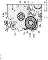
Fig. 2 , the cylinder block front wall (2a) includes an oil supply passage (8) in which a passage outlet (8a) is formed on an inner peripheral surface of the front hole (2e), a fitting component (9) that covers the passage outlet (8a) of the oil supply passage (8) is fitted in the front hole (2e) of the camshaft chamber front wall (2b), and as shown inFig. 3 , the fitting component (9) includes a camshaft oil jet hole (9a) that injects engine oil (7) from the oil supply passage (8) to the camshaft (5). - As shown in
Fig. 3 , since the engine oil (7) is injected from the camshaft oil jet hole (9a) to the camshaft (5), lubrication of a cam (5a) of the camshaft (5) is not hindered although the engine is a shaft-less engine without the predetermined rotation shaft (R) (shown inFig. 10 ) that splashes the engine oil (7) by rotation. - In this manner, even in a shaft-less engine, the lubrication of the cam (5a) of the camshaft (5) is not hindered in a case where the cylinder block (2) is shared by engines having different specifications and distinguished by presence or absence of the predetermined rotation shaft (R).
- As shown in
Fig. 2 , the camshaft (5) includes the cam (5a) that drives the fuel pressure-feed pump (4) inserted into the camshaft chamber (2c). - The predetermined rotation shaft (R) is a PTO shaft (30). PTO is an abbreviation of power take off, and refers to taking out a work output from an engine.
- The predetermined rotation shaft (R) may be a governor shaft or a balancer shaft other than the PTO shaft (30).
- As shown in
Fig. 4 , in this engine, the camshaft chamber front wall (2b) protrudes laterally from the cylinder block front wall (2a), and as shown inFig. 2 , the camshaft chamber (2c) is formed laterally of the cylinder block (2). - As shown in
Fig. 3 , in this engine, the camshaft oil jet hole (9a) is provided in an inner diameter portion (9b) along an inner diameter of the fitting component (9). - In this engine, a degree of freedom in setting an arrangement and an orientation of the camshaft oil jet hole (9a) is high, and an injection direction and an injection position of the engine oil (7) from the camshaft oil jet hole (9a) can be optimized.
- As shown in
Fig. 3 , the engine includes a camshaft input gear (12) of the camshaft (5) on the front side of the camshaft chamber front wall (2b), and as shown inFigs. 3 and4 , the fitting component (9) includes a gear oil jet hole (9c) that injects the engine oil (7) from the oil supply passage (8) to the camshaft input gear (12). - In this engine, since the engine oil (7) from the oil supply passage (8) is injected from the gear oil jet hole (9c) to the camshaft input gear (12), lubricity of the camshaft input gear (12) is high.
- As shown in
Figs. 3 and4 , in this engine, the camshaft oil jet hole (9a) and the gear oil jet hole (9c) are provided in the inner diameter portion (9b) along the inner diameter of the fitting component (9). - In this engine, a degree of freedom in setting an arrangement and an orientation of the camshaft oil jet hole (9a) and the gear oil jet hole (9c) is high, and an injection direction and an injection position of the engine oil (7) from the camshaft oil jet hole (9a) and the gear oil jet hole (9c) can be optimized.
- As shown in
Fig. 3 , in this engine, the fitting component (9) includes a cylindrical collar (9d) fitted in the front hole (2e), the disk-shaped inner diameter portion (9b) along an inner diameter of the collar (9d), a raised portion (9e) extending from an inner peripheral surface of the collar (9d) along front and back surfaces of the inner diameter portion (9b), an oil introduction passage (9f) provided in the raised portion (9e) and communicating with the oil supply passage (8) shown inFig. 2 , and the camshaft oil jet hole (9a) and the gear oil jet hole (9c) led out from the oil introduction passage (9f) as shown inFig. 3 . - As shown in
Fig. 2 , in this engine, the cam (5a) of the camshaft (5) includes three cam noses at 120° intervals in a circumferential direction of the camshaft (5). - With the three cam noses, the fuel supply pump (4a) pumps the liquid fuel to the common rail (3b) at every crank angle of 720° during one combustion cycle at a crank angle of 240°.
- As shown in
Fig. 3 , the camshaft (5) is borne by a camshaft front bearing (5b) internally fitted into the front bearing hole (2d) and a camshaft rear bearing (5c) internally fitted into a rear bearing hole (2k) concentric with the camshaft front bearing (5b), and is installed in the camshaft chamber (2c). - The rear bearing hole (2k) is formed in the camshaft chamber rear wall (2f), and is closed by a camshaft rear plug (2ka).
- The rear hole (2g) is closed by a rear hole plug (2ga).
- As shown in
Fig. 3 , in this engine, the camshaft chamber (2c) includes upper and lower oil mist introduction ports (2n) and (2p) communicating with the inside of the crankcase (2h) and an oil mist outlet port (2q) communicating with the inside of the timing transmission case (10) shown inFig. 4 , oil mist of the engine oil (7) splashed up to the crankshaft (1) in the crankcase (2h) is introduced into the camshaft chamber (2c) from the upper and lower oil mist introduction ports (2n) and (2p) shown inFig. 3 , the cam (5a) of the pump drive camshaft (5) is lubricated, the oil mist in the camshaft chamber (2c) is led out into the timing transmission case (10) from the oil mist outlet port (2q) shown inFig. 4 , and a timing transmission gear train (11) such as the camshaft input gear (12) is lubricated. - As shown in
Fig. 4 , in this engine, the timing transmission case (10) covers the cylinder block front wall (2a) and the camshaft chamber front wall (2b) from the front side, and the timing transmission gear train (11) housed in the timing transmission case (10) includes a crank gear (1a) attached to a crankshaft (1), an idle gear (13) meshed with the crank gear (1a), and the camshaft input gear (12) and a valve camshaft input gear (21a) that are meshed with the idle gear (13). - Gear ratios of the crank gear (1a) to the camshaft input gear (12) and the valve camshaft input gear (21a) of the pump drive camshaft (5) are both two, and the pump drive camshaft (5) and the valve camshaft (21) make one rotation while the crankshaft (1) makes two rotations.
- The configuration of a shaft-equipped engine that shares the cylinder block (2) with a shaft-less engine without the predetermined rotation shaft (R) is as follows.
- As shown in
Figs. 10 to 12 , the engine includes the PTO shaft (30) as the predetermined rotation shaft (R). The PTO shaft (30) includes a PTO shaft input gear (30a), a journal portion (30b), and a slit-shaped PTO shaft output unit (30c) at a rear end. The PTO shaft (30) is borne by the front bearing (30d) fitted in the front hole (2e) and the rear bearing (30e) fitted in the rear hole (2g), and is installed in a lower portion of the camshaft chamber (2c). - PTO output from the PTO shaft (30) is performed by extracting the rear hole plug (2ga) from the rear hole (2g) and connecting an input unit of a work device such as a hydraulic pump to the PTO shaft output unit (30c).
- The predetermined rotation shaft (R) may be a governor shaft or a balancer shaft other than the PTO shaft (30).
- Other structures are the same as the structure of the shaft-less engine shown in
Figs. 1 to 9 . InFigs. 10 to 12 , the same elements as inFigs. 1 to 9 are denoted by the same reference signs as inFigs. 1 to 9 . -
- (1): Crankshaft
- (2a): Cylinder block front wall
- (2b): Camshaft chamber front wall
- (2c): Camshaft chamber
- (2d): Front bearing hole
- (2e): Front hole
- (2f): Camshaft chamber rear wall
- (2g): Rear hole
- (5): Camshaft
- (7): Engine oil
- (8): Oil supply passage
- (8a): Passage outlet
- (9): Fitting component
- (9a): Camshaft oil jet hole
- (9b): Inner diameter portion
- (9c): Gear oil jet hole
- (12): Camshaft input gear
Claims (4)
- An engine comprising:a cylinder block front wall (2a); a camshaft chamber front wall (2b); and a camshaft chamber (2c) provided on a rear side of the camshaft chamber front wall (2b) with an extending direction of a crankshaft (1) defined as a front-rear direction, one side in the front-rear direction defined as a front side, and another side in the front-rear direction defined as the rear side, wherein a camshaft (5) is housed in the camshaft chamber (2c),the camshaft chamber front wall (2b) includes a front bearing hole (2d) of the camshaft (5) and a front hole (2e) disposed below the front bearing hole (2d), and a camshaft chamber rear wall (2f) includes a rear hole (2g) concentric with the front hole (2e),the cylinder block front wall (2a) includes an oil supply passage (8) in which a passage outlet (8a) is formed on an inner peripheral surface of the front hole (2e), a fitting component (9) that covers the passage outlet (8a) of the oil supply passage (8) is fitted in the front hole (2e) of the camshaft chamber front wall (2b), and the fitting component (9) includes a camshaft oil jet hole (9a) that injects engine oil (7) from the oil supply passage (8) to the camshaft (5).
- The engine according to claim 1, wherein the camshaft oil jet hole (9a) is provided in an inner diameter portion (9b) along an inner diameter of the fitting component (9).
- The engine according to claim 1, further comprising:a camshaft input gear (12) of the camshaft (5) on the front side of the camshaft chamber front wall (2b),wherein the fitting component (9) includes a gear oil jet hole (9c) that injects the engine oil (7) from the oil supply passage (8) to the camshaft input gear (12).
- The engine according to claim 3, wherein the camshaft oil jet hole (9a) and the gear oil jet hole (9c) are provided in the inner diameter portion (9b) along the inner diameter of the fitting component (9).
Applications Claiming Priority (2)
| Application Number | Priority Date | Filing Date | Title |
|---|---|---|---|
| JP2022158089A JP7583004B2 (en) | 2022-09-30 | 2022-09-30 | engine |
| PCT/JP2023/030515 WO2024070361A1 (en) | 2022-09-30 | 2023-08-24 | Engine |
Publications (1)
| Publication Number | Publication Date |
|---|---|
| EP4549707A1 true EP4549707A1 (en) | 2025-05-07 |
Family
ID=90477338
Family Applications (1)
| Application Number | Title | Priority Date | Filing Date |
|---|---|---|---|
| EP23871602.1A Pending EP4549707A1 (en) | 2022-09-30 | 2023-08-24 | Engine |
Country Status (5)
| Country | Link |
|---|---|
| US (1) | US20250382906A1 (en) |
| EP (1) | EP4549707A1 (en) |
| JP (1) | JP7583004B2 (en) |
| CN (1) | CN119698516A (en) |
| WO (1) | WO2024070361A1 (en) |
Family Cites Families (5)
| Publication number | Priority date | Publication date | Assignee | Title |
|---|---|---|---|---|
| JPS56117009U (en) * | 1980-02-08 | 1981-09-08 | ||
| JPS6238406U (en) * | 1985-08-27 | 1987-03-07 | ||
| JP2556127Y2 (en) * | 1991-11-08 | 1997-12-03 | 株式会社クボタ | Engine lubrication system |
| JP2005083336A (en) | 2003-09-11 | 2005-03-31 | Kubota Corp | Diesel engine with governor |
| JP6026380B2 (en) | 2013-09-30 | 2016-11-16 | 株式会社クボタ | diesel engine |
-
2022
- 2022-09-30 JP JP2022158089A patent/JP7583004B2/en active Active
-
2023
- 2023-08-24 US US19/100,336 patent/US20250382906A1/en active Pending
- 2023-08-24 CN CN202380059109.XA patent/CN119698516A/en active Pending
- 2023-08-24 EP EP23871602.1A patent/EP4549707A1/en active Pending
- 2023-08-24 WO PCT/JP2023/030515 patent/WO2024070361A1/en not_active Ceased
Also Published As
| Publication number | Publication date |
|---|---|
| WO2024070361A1 (en) | 2024-04-04 |
| JP2024051769A (en) | 2024-04-11 |
| JP7583004B2 (en) | 2024-11-13 |
| CN119698516A (en) | 2025-03-25 |
| US20250382906A1 (en) | 2025-12-18 |
Similar Documents
| Publication | Publication Date | Title |
|---|---|---|
| US7637236B2 (en) | Cylinder head for an overhead-cam internal combustion engine, engine incorporating same, and vehicle incorporating the engine | |
| CA2360001A1 (en) | Mid cam engine | |
| KR101776300B1 (en) | Multi-cylinder diesel engine | |
| US8893609B2 (en) | Engine component including breather apparatus, and engine body incorporating same | |
| JPH08144842A (en) | diesel engine | |
| US5052355A (en) | Lubrication system for two cycle engine | |
| EP4549707A1 (en) | Engine | |
| SE524184C2 (en) | Fuel mixture lubrication of a four-stroke internal combustion engine | |
| US9181883B2 (en) | Four cycle engine carburetors | |
| US8424647B2 (en) | Lubrication system for outboard motor | |
| JP2001012223A (en) | 4 cycle engine | |
| JP5307061B2 (en) | Oil deterioration prevention device for internal combustion engine | |
| US20110056462A1 (en) | Four cycle engine carburetors | |
| EP1055803B1 (en) | Engine device | |
| EP1065357A2 (en) | Engine device | |
| JP2009209853A (en) | Exhaust recirculation system for internal combustion engine | |
| JPH0735126A (en) | Lubricating structure of 2-cycle engine | |
| JPH0547318U (en) | Structure of oil inlet in internal combustion engine | |
| JP6409809B2 (en) | Engine oil supply device | |
| JPS63201308A (en) | diesel engine | |
| JPH0734876A (en) | Secondary combustion chamber of diesel engine | |
| JP2630820B2 (en) | Cam bearing lubrication system for DOHC engine | |
| JP2000213323A (en) | Camshaft lubrication structure | |
| JPS624651Y2 (en) | ||
| JP2021113536A (en) | Lubrication device of internal combustion engine |
Legal Events
| Date | Code | Title | Description |
|---|---|---|---|
| STAA | Information on the status of an ep patent application or granted ep patent |
Free format text: STATUS: THE INTERNATIONAL PUBLICATION HAS BEEN MADE |
|
| PUAI | Public reference made under article 153(3) epc to a published international application that has entered the european phase |
Free format text: ORIGINAL CODE: 0009012 |
|
| STAA | Information on the status of an ep patent application or granted ep patent |
Free format text: STATUS: REQUEST FOR EXAMINATION WAS MADE |
|
| 17P | Request for examination filed |
Effective date: 20250131 |
|
| AK | Designated contracting states |
Kind code of ref document: A1 Designated state(s): AL AT BE BG CH CY CZ DE DK EE ES FI FR GB GR HR HU IE IS IT LI LT LU LV MC ME MK MT NL NO PL PT RO RS SE SI SK SM TR |
|
| DAV | Request for validation of the european patent (deleted) | ||
| DAX | Request for extension of the european patent (deleted) |