EP4549706A1 - Actively driven remote mount optical probe - Google Patents
Actively driven remote mount optical probe Download PDFInfo
- Publication number
- EP4549706A1 EP4549706A1 EP24209289.8A EP24209289A EP4549706A1 EP 4549706 A1 EP4549706 A1 EP 4549706A1 EP 24209289 A EP24209289 A EP 24209289A EP 4549706 A1 EP4549706 A1 EP 4549706A1
- Authority
- EP
- European Patent Office
- Prior art keywords
- probe
- gas turbine
- turbine engine
- main body
- imaging device
- Prior art date
- Legal status (The legal status is an assumption and is not a legal conclusion. Google has not performed a legal analysis and makes no representation as to the accuracy of the status listed.)
- Pending
Links
Images





Classifications
-
- F—MECHANICAL ENGINEERING; LIGHTING; HEATING; WEAPONS; BLASTING
- F01—MACHINES OR ENGINES IN GENERAL; ENGINE PLANTS IN GENERAL; STEAM ENGINES
- F01D—NON-POSITIVE DISPLACEMENT MACHINES OR ENGINES, e.g. STEAM TURBINES
- F01D17/00—Regulating or controlling by varying flow
- F01D17/02—Arrangement of sensing elements
-
- F—MECHANICAL ENGINEERING; LIGHTING; HEATING; WEAPONS; BLASTING
- F01—MACHINES OR ENGINES IN GENERAL; ENGINE PLANTS IN GENERAL; STEAM ENGINES
- F01D—NON-POSITIVE DISPLACEMENT MACHINES OR ENGINES, e.g. STEAM TURBINES
- F01D21/00—Shutting-down of machines or engines, e.g. in emergency; Regulating, controlling, or safety means not otherwise provided for
- F01D21/003—Arrangements for testing or measuring
-
- F—MECHANICAL ENGINEERING; LIGHTING; HEATING; WEAPONS; BLASTING
- F02—COMBUSTION ENGINES; HOT-GAS OR COMBUSTION-PRODUCT ENGINE PLANTS
- F02C—GAS-TURBINE PLANTS; AIR INTAKES FOR JET-PROPULSION PLANTS; CONTROLLING FUEL SUPPLY IN AIR-BREATHING JET-PROPULSION PLANTS
- F02C7/00—Features, components parts, details or accessories, not provided for in, or of interest apart form groups F02C1/00 - F02C6/00; Air intakes for jet-propulsion plants
-
- F—MECHANICAL ENGINEERING; LIGHTING; HEATING; WEAPONS; BLASTING
- F05—INDEXING SCHEMES RELATING TO ENGINES OR PUMPS IN VARIOUS SUBCLASSES OF CLASSES F01-F04
- F05D—INDEXING SCHEME FOR ASPECTS RELATING TO NON-POSITIVE-DISPLACEMENT MACHINES OR ENGINES, GAS-TURBINES OR JET-PROPULSION PLANTS
- F05D2220/00—Application
- F05D2220/30—Application in turbines
- F05D2220/32—Application in turbines in gas turbines
-
- F—MECHANICAL ENGINEERING; LIGHTING; HEATING; WEAPONS; BLASTING
- F05—INDEXING SCHEMES RELATING TO ENGINES OR PUMPS IN VARIOUS SUBCLASSES OF CLASSES F01-F04
- F05D—INDEXING SCHEME FOR ASPECTS RELATING TO NON-POSITIVE-DISPLACEMENT MACHINES OR ENGINES, GAS-TURBINES OR JET-PROPULSION PLANTS
- F05D2260/00—Function
- F05D2260/80—Diagnostics
-
- F—MECHANICAL ENGINEERING; LIGHTING; HEATING; WEAPONS; BLASTING
- F05—INDEXING SCHEMES RELATING TO ENGINES OR PUMPS IN VARIOUS SUBCLASSES OF CLASSES F01-F04
- F05D—INDEXING SCHEME FOR ASPECTS RELATING TO NON-POSITIVE-DISPLACEMENT MACHINES OR ENGINES, GAS-TURBINES OR JET-PROPULSION PLANTS
- F05D2270/00—Control
- F05D2270/80—Devices generating input signals, e.g. transducers, sensors, cameras or strain gauges
- F05D2270/804—Optical devices
-
- G—PHYSICS
- G01—MEASURING; TESTING
- G01J—MEASUREMENT OF INTENSITY, VELOCITY, SPECTRAL CONTENT, POLARISATION, PHASE OR PULSE CHARACTERISTICS OF INFRARED, VISIBLE OR ULTRAVIOLET LIGHT; COLORIMETRY; RADIATION PYROMETRY
- G01J5/00—Radiation pyrometry, e.g. infrared or optical thermometry
- G01J5/0088—Radiation pyrometry, e.g. infrared or optical thermometry in turbines
-
- G—PHYSICS
- G01—MEASURING; TESTING
- G01J—MEASUREMENT OF INTENSITY, VELOCITY, SPECTRAL CONTENT, POLARISATION, PHASE OR PULSE CHARACTERISTICS OF INFRARED, VISIBLE OR ULTRAVIOLET LIGHT; COLORIMETRY; RADIATION PYROMETRY
- G01J5/00—Radiation pyrometry, e.g. infrared or optical thermometry
- G01J5/02—Constructional details
- G01J5/04—Casings
- G01J5/041—Mountings in enclosures or in a particular environment
- G01J5/044—Environment with strong vibrations or shocks
-
- G—PHYSICS
- G01—MEASURING; TESTING
- G01J—MEASUREMENT OF INTENSITY, VELOCITY, SPECTRAL CONTENT, POLARISATION, PHASE OR PULSE CHARACTERISTICS OF INFRARED, VISIBLE OR ULTRAVIOLET LIGHT; COLORIMETRY; RADIATION PYROMETRY
- G01J5/00—Radiation pyrometry, e.g. infrared or optical thermometry
- G01J5/02—Constructional details
- G01J5/08—Optical arrangements
- G01J5/0818—Waveguides
- G01J5/0821—Optical fibres
Definitions
- This disclosure relates to an optical probe, and more particularly to thermal data acquisition using the optical probe.
- Engines such as gas turbine engines, industrial gas turbine engines, and/or the like, can be used to provide thrust to aircraft, other types of vehicles, and electrical generators. During operation of such engines, heat may be produced at some components within the engines.
- thermal imaging Some analysis techniques for gas turbine engine design and, in some cases, turbine airfoil design, utilize thermal imaging. For example, high resolution, full field thermal images allow for effective rotor blade cooling hole mapping, validation of thermal models, and anomaly detection compared to other techniques (e.g., techniques using pyrometers).
- LWIR long-wave infrared
- some other approaches may attempt to allocate a relatively large amount of additional space within the gas turbine engine (e.g., an area between the gaspath casing and fan ducts) for cooling the LWIR camera.
- the area between the gaspath casing and fan ducts is generally occupied by external tubing/cabling which drives the LWIR camera, and the LWIR camera is fan duct mounted.
- the mounting of the LWIR camera to the fan duct creates another problem, as the gaspath casing and the fan ducts can move independent of each other, and some other approaches incorporate some flexibility in the mounting scheme.
- a gas turbine engine including: a fan duct; an engine casing; and a gaspath casing, wherein a thermal imaging device is integrated with the gas turbine engine, the thermal imaging device including: a main body including processing circuitry, wherein the main body is mountable to the fan duct or a mounting structure separate from the fan duct; and a probe mounted to the engine casing, wherein: the probe includes one or more sensors configured to detect thermal energy; and the probe is configured to transmit an optical signal based on the detected thermal energy, to an aperture of the main body, over an air gap between the probe and the main body, wherein the processing circuitry is configured to provide temperature information in response to processing the optical signal.
- the thermal imaging device further includes control circuitry configured to generate one or more control signals associated with maintaining the air gap between an end portion of the probe and the main body.
- the gas turbine engine further includes a target distance of the air gap is in a range of about 6 inches (152mm) to about 12 inches (304mm).
- the thermal imaging device further includes control circuitry configured to generate one or more control signals associated with maintaining an alignment between the probe and the main body.
- the thermal imaging device further includes feedback instrumentation, wherein the feedback instrumentation includes: an emitter integrated with the main body and configured to emit light of an infrared (IR) band; a set of photodetectors located at an end portion of the probe and configured to generate an electrical signal in response to detecting the emitted light; and control circuitry configured to generate, based on the electrical signal, one or more control signals associated with positioning the main body.
- IR infrared
- the IR band is a long-wave IR band.
- the probe at least partially protrudes through and is mounted to the gaspath casing; and the one or more sensors face in a direction toward a rotor blade of the gas turbine engine.
- the main body is located outside of the gas turbine engine.
- the thermal imaging device further includes a shielding structure coupled to the main body, the fan duct, or both.
- the thermal imaging device further includes a motor configured to position the main body based on one or more control signals generated by control circuitry of the thermal imaging device.
- the gas turbine engine further includes a low pressure compressor, a low pressure turbine, a high pressure compressor, and a high pressure turbine; and the thermal energy is associated with at least one of the low pressure compressor, the low pressure turbine, the high pressure compressor, and the high pressure turbine.
- the gas turbine engine is a prototype gas turbine engine.
- a method of controlling a thermal imaging device for a gas turbine engine including: detecting, by a probe of the thermal imaging device, thermal energy associated with the gas turbine engine; transmitting, by the probe, an optical signal based on detected thermal energy associated with the gas turbine engine, wherein the optical signal is transmitted to an aperture of a main body of the thermal imaging device, over an air gap between the probe and the main body; and providing temperature information associated with the gas turbine engine in response to processing the optical signal.
- the method further includes generating, by control circuitry, one or more control signals associated with maintaining the air gap between an end portion of the probe and the main body.
- a target distance of the air gap is in a range of about 6 inches (152mm) to about 12 inches (304mm).
- the method further includes generating, by control circuitry, one or more control signals associated with maintaining an alignment between the probe and the main body.
- the method further includes emitting, by an emitter integrated with the main body, light of an infrared (IR) band; generating, by a set of photodetectors located at an end portion of the probe, an electrical signal in response to detecting the emitted light; and generating, by control circuitry, one or more control signals associated with positioning the main body based on the electrical signal.
- IR infrared
- the IR band is a long-wave IR band.
- an actively driven remote mount LWIR Camera and techniques for mounting the LWIR camera are described which overcome the shortcomings of other approaches. Aspects of the LWIR camera described herein circumvent a reliance on a flexible mounting scheme by separating the gaspath casing mount (associated with the probe of the LWIR camera) and the fan duct mount (associated with the body of the LWIR camera).
- an LWIR camera in which the engine casing mount is disassociated or mechanically separate from the fan duct mount.
- the LWIR camera supports the transmission of an optical signal from the probe to the LWIR camera, over an air gap between the camera mount and the probe mount.
- the LWIR camera in view of the projection of the optical signal over the air gap, includes shielding which overlaps the air gap and prevents the ingress of stray energy into the LWIR camera.
- the LWIR camera is mounted on linear actuators (e.g., linear traverse rails) supportive of driving the LWIR camera along with the probe as the LWIR camera and the probe move independently.
- linear actuators e.g., linear traverse rails
- the techniques described herein may incorporate a feedback loop associated with maintaining the alignment between the LWIR camera and the probe.
- photodetectors or infrared detectors are arrayed about the camera objective such that, based on a determined misalignment associated with the photodetectors or infrared detectors (e.g., should the alignment stray), a correction can be applied to the actuator schedule.
- a control program may control the alignment of the LWIR camera and the probe according to an operation schedule of actuators of the gas turbine engine, in which the operation schedule is based on expected differential thermal excursion of the engine hardware.
- the control program may support an override to allow the photodetectors to correct should a misalignment occur. That is, for example, the control program may support correcting the alignment between the LWIR camera and the probe based on a misalignment detected using the photodetectors.
- aspects of the present disclosure support additional and/or alternative techniques for positional correction and alignment of the LWIR camera and/or the probe.
- the control program may support implementing positional correction and alignment based on the image (e.g., image data) collected by the LWIR camera.
- Other non-limiting examples of feedback based on which the control program may implement positional correction and alignment include proximity measurements, strain measurements, and temperature measurements provided by corresponding hardware components.
- the techniques described herein include positional correction with respect to one or more axes (e.g., all three axes) using positional correction/alignment and feedback information as described herein.
- modularity features described herein support flexibility in positioning and improved repairability of the LWIR camera.
- the modularity features support mounting of the LWIR camera body at the outside of the gas turbine engine, which disassociates camera cooling requirements from the probe. Accordingly, for example, the modularity features support integration with the gas turbine engine for thermal imaging of the gas turbine engine, without relatively complex or heavy modifications to the structure of the gas turbine engine.
- the example modularity features and alignment features described herein support the realization of an LWIR camera capable of gathering thermal data associated with validating an airfoil design (e.g., airfoil thermal data on development engines), in which the time/cost integrating the LWIR camera with the development engines is reduced compared to other approaches.
- the techniques and LWIR camera described herein may be implemented in association with validating any suitable rotating hardware design (e.g., gas turbine engine, aircraft engines, and the like).
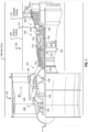
- FIG. 1 schematically illustrates a gas turbine engine 120.
- the gas turbine engine 120 is disclosed herein as a two-spool turbofan that generally incorporates a fan section 122, a compressor section 124, a combustor section 126 and a turbine section 128.
- Alternative engines might include other systems or features.
- the fan section 122 drives air along a bypass flow path B in a bypass duct 123, while the compressor section 124 drives air along a core flow path C for compression and communication into the combustor section 126 then expansion through the turbine section 128.
- tail refers to the direction associated with the tail (e.g., the back end) of an aircraft, or generally, to the direction of exhaust of the gas turbine engine (to the right in FIG. 1 ).
- forward refers to the direction associated with the nose (e.g., the front end) of an aircraft, or generally, to the direction of flight or motion (to the left in FIG. 1 ).
- the gas turbine engine 120 generally includes a low speed spool 130 and a high speed spool 132 mounted for rotation about an engine central longitudinal axis A relative to an engine static structure 136 via several bearing systems 138. It should be understood that various bearing systems 138 at various locations may alternatively or additionally be provided, and the location of bearing systems 138 may be varied as appropriate to the application.
- the low speed spool 130 generally includes an inner shaft 140 that interconnects a fan 142, a first or low pressure compressor 144 and a first or low pressure turbine 146.
- the inner shaft 140 is connected to the fan 142 through a speed change mechanism, which in gas turbine engine 120 is illustrated as a geared architecture 148 to drive the fan 142 at a lower speed than the low speed spool 130.
- the high speed spool 132 includes an outer shaft 150 that interconnects a second or high pressure compressor 152 and a second or high pressure turbine 154.
- a combustor 156 is arranged in gas turbine engine 120 between the high pressure compressor 152 and the high pressure turbine 154.
- a mid-turbine frame 157 of the engine static structure 136 is arranged generally between the high pressure turbine 154 and the low pressure turbine 146.
- the mid-turbine frame 157 further supports bearing systems 138 in the turbine section 128.
- the inner shaft 140 and the outer shaft 150 are concentric and rotate via bearing systems 138 about the engine central longitudinal axis A which is collinear with their longitudinal axes.
- the core airflow is compressed by the low pressure compressor 144 then the high pressure compressor 152, mixed and burned with fuel in the combustor 156, then expanded over the high pressure turbine 154 and low pressure turbine 146.
- the mid-turbine frame 157 includes airfoils which are in the core airflow path C.
- the turbines 146, 154 rotationally drive the respective low speed spool 130 and high speed spool 132 in response to the expansion.
- gear system 148 may be located aft of combustor section 126 or even aft of turbine section 128, and fan section 122 may be positioned forward or aft of the location of gear system 148.
- the gas turbine engine 120 includes a fan duct 160, an engine casing 165, and a gaspath casing 170.
- Features of the gas turbine engine 120 e.g., the fan duct 160, engine casing 165, and gaspath casing 170 are not necessarily drawn to scale, and shapes and positions thereof are not limited to the examples illustrated herein.
- the gas turbine engine 120 may be integrated with the fan 122 in a fan case assembly.
- Example aspects of an LWIR camera 200 which may be integrated with the gas turbine engine 120 in association with providing thermal imaging data (e.g., of a rotor blade located upstream or downstream of a probe 220 of the LWIR camera 200) are described herein with reference to the following figures.
- the LWIR camera 200 may provide thermal imaging data of a rotor blade 159 (e.g., rotor blade 159-a, rotor blade 159-b) associated with the low pressure turbine 146.
- the LWIR camera 200 may also be referred to herein as a LWIR camera system, a thermal imaging device, a thermal imaging camera system, a thermal imaging system, or the like.
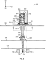
- the LWIR camera 200 may include a main body 205 (also referred to herein as a housing). In the example of FIG. 2 , the main body 205 is located outside of the gas turbine engine 120. According to one or more embodiments of the present disclosure, as the main body 205 is located outside the gas turbine engine 120, the LWIR camera 200 may be integrated with the gas turbine engine 120 without camera cooling (or with substantially less camera cooling compared to some other techniques).
- the main body 205 is mountable to surfaces of the gas turbine engine 120.
- the main body 205 is mountable to the fan duct 160 (e.g., to an outer surface of the fan duct 160), as illustrated in the configuration of FIG. 2 .
- the main body 205 is mountable to a mounting structure separate from the fan duct 160, example aspects of which are later described with reference to FIG. 3 .
- the main body 205 may include or house a camera module 201 and processing circuitry 202 supportive of generating thermal images associated with the gas turbine engine 120.
- the main body 205 may include or control circuitry 204 supportive of movement control of the main body 205 (e.g., by controlling the motor 215 and/or the radial traverse 210).
- the processing circuitry 202 and/or the control circuitry 204 may be located outside of the main body 205 (e.g., included in a housing separate from the main body 205).
- the LWIR camera 200 is mounted on linear actuators 211 (also referred to herein as linear traverse rails).
- the processing circuitry 202 supports controlling the movement of the main body 205 (and camera module 201) along with the probe 220, thereby maintaining alignment between the main body 205 (and camera module 201) and the probe 220.
- the processing circuitry 202 may support controlling movement of the main body 205 to compensate for any misalignment that may occur, as the physical separation of the main body 205 (and camera module 201) and the probe 220 allows for the main body 205 and probe 220 to move independent of one another.
- Example aspects of feedback instrumentation utilized in association with maintaining the alignment are later described herein.
- the LWIR camera 200 includes a probe 220.
- the probe 220 is mountable to the engine casing 165 (e.g., to an outer surface of the casing 165).
- the probe 220 includes one or more sensors 221 configured to detect thermal energy.
- the main body 205 and the probe 220 may be physically and mechanically separate.
- the probe 220 is configured to generate and transmit an optical signal 223 based on the detected thermal energy.
- the optical signal 223 may include data representative of the detected thermal energy.
- the optical signal 223 may include measurement data associated with the detected thermal energy.
- the probe 220 may transmit the optical signal 223 to the main body 205 over an air gap 207 between the probe 220 and the main body 205.
- the air gap 207 is less than a distance between the fan duct 160 and the engine casing 165.
- the optical design of the LWIR camera 200 and the air gap 207 may accommodate a specific length from an end portion of the probe 220 (e.g., probe exit) to the entrance of the LWIR camera 200.
- the length may be a distance between the end portion of the probe 220 and the camera entrance of the camera module 201.
- the probe 220 may transmit, and the main body 205 may receive, the optical signal 223 via an aperture 206 of the main body 205.
- the processing circuitry 202 is configured to provide temperature information in response to processing the optical signal 223.
- the LWIR camera 200 includes a shielding structure 225.
- the shielding structure 225 may preclude stray energy from entering the main body 205 (and camera module 201).
- the shielding structure 225 may be coupled to the main body 205 and/or the fan duct 160.
- the shielding structure 225 may protrude through the fan duct 160 and extend in a direction (e.g., direction D2) perpendicular to the fan duct 160, towards the engine casing 165.
- an inner area of the shielding structure 225 e.g., defined with respect to a plane D1-D3 at least partially overlaps the aperture 206 of the main body 205.
- the thermal energy detected by the probe 220 may be associated with a rotor blade 159 (e.g., rotor blade 159-a) of the gas turbine engine 120.
- the probe 220 is mounted to the engine casing 165 and extends across a secondary air cavity between the engine casing 165 and the gaspath casing 170.
- the probe 220 at least partially protrudes through the gaspath casing 170 (e.g., in direction D2) and into a stator vane 158 (also referred to herein as an ingress stator vane or an ingress airfoil) of the gas turbine engine 120.
- the probe 220 may include a reflective element 222 including a reflective surface.
- the reflective element 222 may relay light received at the reflective element 222 to the sensor 221.
- the example configuration is not limited to the positioning of elements described herein, and it is to be understood that the sensor 221 and the reflective element 222 of the probe 220 may be positioned at different locations of the probe 220.
- sensor 221 e.g., if positioned at the end of the probe 220
- reflective element 222 may be at least partially exposed (e.g., in direction D1, toward rotor blade 159-a) by an opening formed in the stator vane 158.
- the probe 220 may be capable of detecting thermal energy associated with rotor blade 159-a.
- a rotor blade 159-b is adjacent the stator vane 158 but not included in the thermal measurement.
- the LWIR camera 200 may further include a gaseous nitrogen (GN2) cooling and purge inlet 230.
- the purge inlet 230 may be coupled to or integrated with the probe 220.
- the LWIR camera 200 may further include a camera purge outlet 212 (e.g., capable of purging GN2 or air).
- the LWIR camera 200 may be a camera designed to measure infrared electromagnetic radiation practically defined as the 8 ⁇ m to 14 ⁇ m spectral band.
- the LWIR camera 200 may include additional components 235.
- the additional components 235 may include, for example, a series of lens and mirrors including an optical system to focus and direct the infrared electromagnetic radiation.
- the LWIR camera 200 may include an electrical system (not illustrated) to digitize, amplify, and transmit data signals representative of the infrared electromagnetic radiation to a data acquisition system.
- the probe 220 may be implemented without optical fiber.
- the probe 220 is absent any optical fiber and may support transmission of signals and light as described herein (e.g., data signals, infrared light, infrared signals, LWIR signals, and the like) without fiber optics.
- one or more gaps between one or more lenses and/or one or more mirrors of the LWIR camera 200 may be air gaps.
- all gaps between one or more lenses and/or one or more mirrors of the LWIR camera 200 may be air gaps.
- use of the air gaps for signal and light transmission as described herein may provide advantages of improved reliability compared to transmission using fiber optics.
- the probe 220 may be referred to as an optical probe.
- the LWIR camera 200 includes feedback instrumentation.
- the feedback instrumentation may be coupled to at least one of the fan duct 160, the engine casing 165, and the probe 220.
- the feedback instrumentation is configured to provide electrical signals based on movement of at least one of the fan duct 160, the engine casing 165, and the probe 220.
- the control circuitry 204 may generate control signals associated with maintaining an alignment between the main body 205 and the probe 220 based on the electrical signals. For example, the control circuitry 204 may transmit a control signal to radial traverse 210 and/or motor 215, thereby controlling the main body 205 to maintain alignment with the probe 220. In some examples, the control circuitry 204 may transmit the control signal in association with controlling the main body 205 to maintain the air gap 207 (e.g., maintain a target distance between the main body 205 and the probe 220). In some embodiments, the target distance of the air gap 207 may be in a range of about 6 inches (152mm) to about 12 inches (304mm). However, embodiments of the present disclosure are not limited thereto, and target distance of the air gap 207 may be a distance suitable for signal and light transmission between the probe 220 and the main body 205 (e.g., camera components included in the main body 205).
- control circuitry 204 may generate and provide, to the camera module 201, control signals associated with adjusting parameters (e.g., image capture parameters) of the camera module 201.
- adjusting parameters e.g., image capture parameters
- Non-limiting examples of the feedback instrumentation are later described herein.
- FIG. 3 is a schematic illustrating an example configuration 300 integrating the LWIR camera 200 with a gas turbine engine 120 in accordance with one or more embodiments of the present disclosure. Repeated descriptions of the LWIR camera 200 and the gas turbine engine 120 are omitted for brevity.
- the main body 205 is mounted to a mounting structure 240.
- the mounting structure 240 may be physically separate from the fan duct 160.
- the mounting structure 240 may be a camera mount support fixed to an object or surface different from the fan duct 160.
- the mounting structure 240 may be fixed to the ground, a stationary cart, or the like.
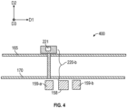
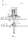
- FIG. 4 is a schematic illustrating a configuration 400 utilizing a probe 220-b of the LWIR camera 200 in accordance with one or more embodiments of the present disclosure.
- the probe 220-b includes aspects of the probe 220 described herein (e.g., with reference to FIGS. 2 and 3 ), and repeated descriptions of like elements are omitted for brevity. Repeated descriptions of the LWIR camera 200 and the gas turbine engine 120 are omitted for brevity.
- sensor 221 faces in a direction (e.g., direction D2) perpendicular to the gaspath casing 170 and toward the rotor blade 159-a.
- the probe 220-b protrudes through an opening of the gaspath casing 170, enabling the sensor 221 to detect thermal energy associated with the rotor blade 159-a.
- the probe 220-b may be implemented without the reflective element 222 of FIG. 1 , as the sensor 221 may face directly toward the rotor blade 159-a.
- probe 220-b is a radial viewing probe facing inboard at a target airfoil (e.g., rotor blade 159-a) thru a case mounted objective.
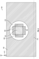
- FIG. 5 illustrates a cross-sectional view 500 taken along line A-A of FIG. 1 .
- the cross-sectional view 500 is a plan view including the fan duct 160 and a sensing face 501 of the probe 220, positioned with respect to an engine centerline 515 of the gas turbine engine 120.
- the sensing face 501 may be exposed by an opening 510 formed in the fan duct 160.
- the sensing face 501 may be located at an end portion of the probe 220.
- the photodetectors 505 may be located at an end portion (e.g., at sensing face 501) of the probe 220.
- the photodetectors 505 may be configured to generate electrical signals in response to detecting emitted light of an infrared band.
- the LWIR camera 200 may include an emitter (emission device) integrated with and/or housed in the main body 205, and the emitter may be configured to emit the light of the infrared band.
- the infrared band is a long-wave IR (LWIR) band.
- LWIR long-wave IR
- the light emitted by the emitter may have a wavelength ranging from 8 ⁇ m to 14 ⁇ m.
- the example aspects of the photodetectors 505 and the emitter are not limited to the example wavelengths and frequency bands described herein.
- aspects of the present disclosure support implementations using other suitable wavelengths or frequency bands associated with inspecting the gas turbine engine 120.
- the photodetectors 505 may provide data indicative of real-time relative movements between the probe 220 (and thereby the engine casing 165) and the main body 205 according to 3 axes (e.g., with respect to the D1, D2, and D3 directions). Based on electrical signals from photodetectors 505 (e.g., as generated in response to energy detected by the photodetectors 505), the processing circuitry 202 and/or control circuitry 204 may generate and provide control signals to radial traverse 210, motor 215, and/or camera module 201 as described herein.
- the probe 220 (and sensing face 501) includes four photodetectors 505, but aspects of the present disclosure are not limited thereto.
- the probe 220 may include any suitable quantity and/or configuration of photodetectors 505 for maintaining or correcting an alignment between the LWIR camera 200 and the probe 220.
- FIG. 6 is a schematic illustrating a configuration 600 utilizing probe 220 of the LWIR camera 200 in accordance with one or more embodiments of the present disclosure. Repeated descriptions of the LWIR camera 200 and the gas turbine engine 120 are omitted for brevity. Some identifiers associated with components of the LWIR camera 200 and the gas turbine engine 120 are omitted so as not to obstruct from the discussion of FIG. 6 .
- the feedback instrumentation includes proximity probes 605 coupled to the fan duct 160.
- proximity probe 605-a is coupled to a probe bracket 610-a
- proximity probe 605-b is coupled to a probe bracket 610-b
- the probe bracket 610-a and probe bracket 610-b are coupled to (e.g., rigidly mounted to) the fan duct 160.
- the feedback instrumentation further includes a target structure 615-a and a target structure 615-b coupled to (e.g., rigidly mounted to) the engine casing 165.
- aspects of the present disclosure not limited thereto.
- a probe bracket 610 (and corresponding proximity probe 605) may be coupled to the engine casing 165, and a corresponding target structure 615 may be coupled to the fan duct 160.
- both probe brackets 610 (and corresponding proximity probes 605) may be coupled to the engine casing 165, and both target structures 615 may be coupled to the fan duct 160.
- the proximity probes 605 may provide data indicative of real-time relative movements between the fan duct 160 and engine casing 165 according to 3 axes (e.g., with respect to the D1, D2, and D3 directions).
- proximity probe 605-a is capable of providing radial measurements.
- proximity probe 605-b is capable of providing axial measurements.
- proximity probe 605-b may be rotated 90 degrees to provide tangential deflection measurements.
- the proximity probes 605 may provide electrical signals indicative of the radial measurements, axial measurements, and/or tangential deflection measurements to the processing circuitry 202 and/or control circuitry 204. Based on the electrical signals from the proximity probes 605, the processing circuitry 202 and/or control circuitry 204 may generate and provide control signals to radial traverse 210, motor 215, and/or camera module 201 as described herein.
- FIG. 7 is a schematic illustrating a configuration 700 utilizing probe 220 of the LWIR camera 200 in accordance with one or more embodiments of the present disclosure. Repeated descriptions of the LWIR camera 200 and the gas turbine engine 120 are omitted for brevity. Some identifiers associated with components of the LWIR camera 200 and the gas turbine engine 120 are omitted so as not to obstruct from the discussion of FIG. 7 .
- Each LVDT 705 is an electromechanical transducer capable of converting motion of an object (e.g., a duct side mount 710, a case side mount 715) to which the LVDTs 705 is coupled mechanically into a corresponding electrical signal.
- an object e.g., a duct side mount 710, a case side mount 715
- the feedback instrumentation includes LVDTs 705 coupled to the fan duct 160 and the engine casing 165.
- LVDT 705-a is coupled to a duct side mount 710-a and a case side mount 715-a
- LVDT 705-b is coupled to a duct side mount 710-b and a case side mount 715-b.
- the duct side mount 710-a and duct side mount 710-b are coupled to (e.g., rigidly mounted to) the fan duct 160
- the case side mount 715-a and case side mount 715-b are coupled to (e.g., rigidly mounted to) the engine casing 165.
- the LVDTs 705 may provide data indicative of real-time relative movements between the fan duct 160 and engine casing 165 according to 3 axes (e.g., with respect to the D1, D2, and D3 directions).
- LVDT 705-a is capable of providing radial measurements.
- LVDT 705-b is capable of providing axial measurements.
- LVDT 705-b may be rotated 90 degrees to provide tangential deflection measurements.
- the LVDTs 705 may provide electrical signals indicative of the radial measurements, axial measurements, and/or tangential deflection measurements to the processing circuitry 202 and/or control circuitry 204. Based on the electrical signals from the LVDTs 705, the processing circuitry 202 and/or control circuitry 204 may generate and provide control signals to radial traverse 210, motor 215, and/or camera module 201 as described herein.
- FIG. 8 is a schematic illustrating a configuration 800 utilizing probe 220 of the LWIR camera 200 in accordance with one or more embodiments of the present disclosure. Repeated descriptions of the LWIR camera 200 and the gas turbine engine 120 are omitted for brevity. Some identifiers associated with components of the LWIR camera 200 and the gas turbine engine 120 are omitted so as not to obstruct from the discussion of FIG. 8 .
- Each strain gage 805 is a sensor having a resistance which varies with applied force.
- each strain gage 805 is coupled to an elastic member 810 and converts force, pressure, tension, or the like associated with the elastic member 810 into a change in electrical resistance.
- the feedback instrumentation includes elastic member 810-a and elastic member 810-b each coupled to (e.g., rigidly mounted to) the fan duct 160 and the engine casing 165.
- strain gage 805-a is coupled to elastic member 810-a
- strain gage 805-b is coupled to elastic member 810-b.
- strain gage 805 may provide data indicative of real-time relative movements between the fan duct 160 and engine casing 165 according to 3 axes (e.g., with respect to the D1, D2, and D3 directions).
- strain gage 805-a is capable of providing electrical resistance measurements (or changes in electrical resistance) that correspond to radial movement/measurements.
- strain gage 805-b is capable of providing electrical resistance measurements (or changes in electrical resistance) that correspond to axial movement/measurements.
- strain gage 805-b may be rotated 90 degrees to provide tangential deflection movement/measurements.
- the strain gages 805 may provide electrical signals indicative of the electrical resistance measurements (which correspond to radial, axial, and/or tangential deflection movement/measurements) to the processing circuitry 202 and/or control circuitry 204. Based on the electrical signals from the strain gages 805, the processing circuitry 202 and/or control circuitry 204 may generate and provide control signals to radial traverse 210, motor 215, and/or camera module 201 as described herein.
- FIG. 9 is a schematic illustrating a configuration 900 utilizing probe 220 of the LWIR camera 200 in accordance with one or more embodiments of the present disclosure. Repeated descriptions of the LWIR camera 200 and the gas turbine engine 120 are omitted for brevity. Some identifiers associated with components of the LWIR camera 200 and the gas turbine engine 120 are omitted so as not to obstruct from the discussion of FIG. 9 .
- thermocouple 905, thermocouple 910 An example of feedback instrumentation (e.g., thermocouple 905, thermocouple 910) supportive of maintaining or correcting an alignment between the LWIR camera 200 and the probe 220 in accordance with one or more embodiments of the present disclosure is described herein with reference to FIG. 8 .
- the thermocouples (e.g., thermocouple 905, thermocouple 910) described herein may be metal thermocouples which may be used to provide real-time relative movements between the fan duct 160 and engine casing 165 in the axial direction.
- thermocouple 905 is capable of determining temperature at a location on the fan duct 160 to which the thermocouple 905 is coupled
- each thermocouple 910 is capable of determining temperature at a location on the engine casing 165 to which the thermocouple 910 is coupled.
- the feedback instrumentation includes a series of thermocouples 905 along the fan duct 160 and a series of thermocouples 910 along the engine casing 165.
- thermocouples 905 and thermocouples 910 may provide electrical signals indicative of the determined temperatures to the processing circuitry 202 and/or control circuitry 204. Based on the electrical signals from the thermocouples 905 and thermocouples 910, the processing circuitry 202 and/or control circuitry 204 may determine average temperatures of the fan duct 160 and/or the engine casing 165, thermal growth associated with the fan duct 160 and/or the engine casing 165, and accordingly, relative deflection of the fan duct 160 and/or the engine casing 165.
- the processing circuitry 202 and/or control circuitry 204 may determine relative position of the probe 220 to the main body 205, and accordingly, generate and provide control signals to radial traverse 210, motor 215, and/or camera module 201 as described herein.
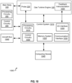
- FIG. 10 depicts an example of a control system 1000 in accordance with one or more embodiments of the present disclosure.
- the control system 1000 is configured to monitor and control operation of a gas turbine engine (e.g., the gas turbine engine 120) and/or the LWIR camera 200 in real-time (or near-real time) according to one or more embodiments described herein.
- a gas turbine engine e.g., the gas turbine engine 120
- the LWIR camera 200 in real-time (or near-real time) according to one or more embodiments described herein.
- control system 1000 performs the functionality of a data acquisition system by receiving, processing, storing and/or reporting data received from feedback instrumentation 1005 (e.g., photodetectors 505, proximity probes 605, LVDTs 705, strain gages 805, thermocouples 905, and the like described herein).
- feedback instrumentation 1005 e.g., photodetectors 505, proximity probes 605, LVDTs 705, strain gages 805, thermocouples 905, and the like described herein.
- the control system 1000 can control functions of the gas turbine engine 120 and/or the LWIR camera 200 by generating one or more commands.
- the control system 1000 can be a full authority digital engine control (FADEC) that includes processing circuitry 1015 (also referred to as a "processing device”), control circuitry 1020, and a memory system 1025 (also referred to as a "memory”) configured to store a plurality of configuration items, where at least one of the configuration items includes a sequence of the computer executable instructions for execution by the processing circuitry 1015.
- FADEC full authority digital engine control
- processing circuitry 1015 also referred to as a "processing device”
- control circuitry 1020 also referred to as a "memory”
- memory system 1025 also referred to as a "memory”
- Other types of configuration items can include data, such as constants, configurable data, and/or fault data.
- Examples of computer executable instructions can include boot software, operating system software, and/or application software.
- the executable instructions may be stored or organized in any manner and at any level of abstraction, such as in connection with controlling and/or monitoring operation of the gas turbine engine 120.
- the processing circuitry 1015 can be any type or combination of central processing unit (CPU), including one or more of a microprocessor, a digital signal processor (DSP), a microcontroller, an application specific integrated circuit (ASIC), a field programmable gate array (FPGA), or the like.
- the memory system 1025 may include volatile memory, such as random access memory (RAM), and non-volatile memory, such as Flash memory, read only memory (ROM), and/or other electronic, optical, magnetic, or any other computer readable medium onto which is stored data and algorithms in a non-transitory form.
- the control system 1000 can also include one or more of an input/output interface 1035, a communication interface 1030, and/or other elements.
- the input/output interface 1035 can include support circuitry for interfacing with the LWIR camera 200 (e.g., camera module 201, processing circuitry 202, control circuitry 204, probe 220) and feedback instrumentation 1005, such as filters, amplifiers, digital-to-analog converters, analog-to-digital converters, and other such circuits to support digital and/or analog interfaces. Further, the input/output interface 1035 can receive or output signals to/from other sources, such as discrete inputs/outputs and/or status signals.
- the control system 1000 provides for, among other things, monitoring the gas turbine engine 120 based on data collected by the LWIR camera 200 (e.g., camera module 201, probe 220) and feedback instrumentation 1005.
- the gas turbine engine 120 is one example of an aircraft engine, and other examples are also possible, such as hybrid electric turbine engines. It may be desirable to monitor properties of the gas turbine engine 120, such as temperature, pressure, flow rate, etc. to detect problems, such as anomalies, with the gas turbine engine 120.
- FIG. 11 is a block diagram 1100 supportive of a camera positioning program 1101 (e.g., maintaining or correcting alignment between a LWIR camera 200 and a probe 220) in association with obtaining thermal measurements, in accordance with one or more embodiments of the present disclosure. Aspects the features described with reference to block diagram 1100 may be implemented by the example aspects of control system 1000 as described herein.
- a camera positioning program 1101 e.g., maintaining or correcting alignment between a LWIR camera 200 and a probe 220
- FIG. 11 is a block diagram 1100 supportive of a camera positioning program 1101 (e.g., maintaining or correcting alignment between a LWIR camera 200 and a probe 220) in association with obtaining thermal measurements, in accordance with one or more embodiments of the present disclosure. Aspects the features described with reference to block diagram 1100 may be implemented by the example aspects of control system 1000 as described herein.
- Base program 1105 includes configurations supportive of a defined analytical use case (e.g., expected case and expected duct excursions).
- the camera positioning program 1101 includes a feedback loop incorporating input data 1110 from feedback instrumentation (e.g., photodetectors 505, proximity probes 605, LVDTs 705, strain gages 805, thermocouples 905) described herein. Based on the data from the feedback instrumentation, the camera positioning program 1101 provides correction (at 1115) to the base program 1105. For example, The correction to the base program may address uncertainty or errors in the analytical predictions. In an example, if the fan ducting excursion lags the engine casing excursion by more than predicted, the signal exiting the probe 220 may become misaligned with the camera objective, which may result in a potential loss of signal/measurement/data collection.
- feedback instrumentation e.g., photodetectors 505, proximity probes 605, LVDTs 705, strain gages 805, thermocouples 905
- the camera positioning program 1101 may provide real-time correction for the misalignment and mitigate the aforementioned shortfall.
- the camera positioning program 1101 may alternatively and/or additionally incorporate feedback 1112 from the LWIR camera 200 for positional correction.
- the feedback 1112 may include data indicating whether an image is out of focus and/or data indicating positioning adjustments for adjusting the focus, and the camera positioning program 1101 may provide correction (at 1115) to the base program 1105 based on the feedback 1112.
- the camera positioning program 1101 may provide a camera positioning output 1120 (e.g., positioning commands for the LWIR camera 200) based on the base program 1105 and the correction as provided at 1115.
- the camera positioning program 1101 may incorporate feedback from one or more sources (e.g., photodetectors 505, proximity probes 605, and the like described herein) based on which to provide correction associated with the base program 1105 and/or camera positioning.
- sources e.g., photodetectors 505, proximity probes 605, and the like described herein
- FIG. 12 illustrates an example flowchart of a method 1200 of controlling a thermal imaging device (e.g., LWIR camera 200) for a gas turbine engine in accordance with one or more embodiments of the present disclosure.
- the method 1200 may be implemented by the example aspects of a LWIR camera 200 and/or a control system 1010 as described herein.
- the method includes transmitting, by the probe, an optical signal based on detected thermal energy associated with the gas turbine engine, wherein the optical signal is transmitted to an aperture of a main body of the thermal imaging device, over an air gap between the probe and the main body.
- the method includes generating, by control circuitry, one or more control signals associated with maintaining the air gap between an end portion of the probe and the main body.
- a target distance of the air gap is in a range of about 6 inches (152mm) to about 12 inches (304mm).
- the method includes generating, by control circuitry, one or more control signals associated with maintaining an alignment between the probe and the main body.
- the method includes emitting, by an emitter integrated with the main body, light of an infrared (IR) band; generating, by a set of photodetectors located at an end portion of the probe, an electrical signal in response to detecting the emitted light; and generating, by control circuitry, one or more control signals associated with positioning the main body based on the electrical signal.
- IR infrared
- the IR band is a long-wave IR band.
- the operations may be performed in a different order than the order shown, or the operations may be performed in different orders or at different times. Certain operations may also be left out of the flowcharts, one or more operations may be repeated, or other operations may be added to the flowcharts.
Landscapes
- Engineering & Computer Science (AREA)
- Mechanical Engineering (AREA)
- General Engineering & Computer Science (AREA)
- Chemical & Material Sciences (AREA)
- Combustion & Propulsion (AREA)
- Length Measuring Devices By Optical Means (AREA)
Abstract
A gas turbine engine (120) includes a fan duct (160), an engine casing (165), and a gaspath casing (170). A thermal imaging device (200) is integrated with the gas turbine engine (120). The thermal imaging device (200) includes: a main body (205) comprising processing circuitry (202), where the main body (205) is mountable to the fan duct (160) or a mounting structure (240) separate from the fan duct (160). The thermal imaging device (200) includes a probe (220) mounted to the engine casing (165). The probe (220) includes one or more sensors (221) configured to detect thermal energy, and the probe (220) is configured to transmit an optical signal based on the detected thermal energy, to an aperture (206) of the main body (205), over an air gap (207) between the probe (220) and the main body (205). The processing circuitry (202) is configured to provide temperature information in response to processing the optical signal.
Description
- This disclosure relates to an optical probe, and more particularly to thermal data acquisition using the optical probe.
- Engines, such as gas turbine engines, industrial gas turbine engines, and/or the like, can be used to provide thrust to aircraft, other types of vehicles, and electrical generators. During operation of such engines, heat may be produced at some components within the engines.
- Some analysis techniques for gas turbine engine design and, in some cases, turbine airfoil design, utilize thermal imaging. For example, high resolution, full field thermal images allow for effective rotor blade cooling hole mapping, validation of thermal models, and anomaly detection compared to other techniques (e.g., techniques using pyrometers).
- However, approaches which utilize a long-wave infrared (LWIR) camera for thermal imaging of a gas turbine engine (e.g., for thermal imaging of turbine airfoils), the LWIR camera does not lend itself to gas turbine integration given the available volume within the gas turbine engine. For example, the LWIR camera can be relatively large compared to the available volume within the gas turbine engine.
- In some cases, depending on proximity of the LWIR camera to the gaspath of the gas turbine engine, some other approaches may attempt to allocate a relatively large amount of additional space within the gas turbine engine (e.g., an area between the gaspath casing and fan ducts) for cooling the LWIR camera. However, in some cases, the area between the gaspath casing and fan ducts is generally occupied by external tubing/cabling which drives the LWIR camera, and the LWIR camera is fan duct mounted. The mounting of the LWIR camera to the fan duct creates another problem, as the gaspath casing and the fan ducts can move independent of each other, and some other approaches incorporate some flexibility in the mounting scheme.
- Techniques for providing analysis of gas turbine engine design and, in some cases, turbine airfoil design are desired.
- According to an aspect of the present invention, there is provided a gas turbine engine including: a fan duct; an engine casing; and a gaspath casing, wherein a thermal imaging device is integrated with the gas turbine engine, the thermal imaging device including: a main body including processing circuitry, wherein the main body is mountable to the fan duct or a mounting structure separate from the fan duct; and a probe mounted to the engine casing, wherein: the probe includes one or more sensors configured to detect thermal energy; and the probe is configured to transmit an optical signal based on the detected thermal energy, to an aperture of the main body, over an air gap between the probe and the main body, wherein the processing circuitry is configured to provide temperature information in response to processing the optical signal.
- In an embodiment of the above, the thermal imaging device further includes control circuitry configured to generate one or more control signals associated with maintaining the air gap between an end portion of the probe and the main body.
- In a further embodiment of any of the above, the gas turbine engine further includes a target distance of the air gap is in a range of about 6 inches (152mm) to about 12 inches (304mm).
- In a further embodiment of any of the above, the thermal imaging device further includes control circuitry configured to generate one or more control signals associated with maintaining an alignment between the probe and the main body.
- In a further embodiment of any of the above, the thermal imaging device further includes feedback instrumentation, wherein the feedback instrumentation includes: an emitter integrated with the main body and configured to emit light of an infrared (IR) band; a set of photodetectors located at an end portion of the probe and configured to generate an electrical signal in response to detecting the emitted light; and control circuitry configured to generate, based on the electrical signal, one or more control signals associated with positioning the main body.
- In a further embodiment of any of the above, the IR band is a long-wave IR band.
- In a further embodiment of any of the above, the probe at least partially protrudes through and is mounted to the gaspath casing; and the one or more sensors face in a direction toward a rotor blade of the gas turbine engine.
- In a further embodiment of any of the above, the main body is located outside of the gas turbine engine.
- In a further embodiment of any of the above, the thermal imaging device further includes a shielding structure coupled to the main body, the fan duct, or both.
- In a further embodiment of any of the above, the thermal imaging device further includes a motor configured to position the main body based on one or more control signals generated by control circuitry of the thermal imaging device.
- In a further embodiment of any of the above, the gas turbine engine further includes a low pressure compressor, a low pressure turbine, a high pressure compressor, and a high pressure turbine; and the thermal energy is associated with at least one of the low pressure compressor, the low pressure turbine, the high pressure compressor, and the high pressure turbine.
- In a further embodiment of any of the above, the gas turbine engine is a prototype gas turbine engine.
- According to a further aspect there is provided a method of controlling a thermal imaging device for a gas turbine engine, including: detecting, by a probe of the thermal imaging device, thermal energy associated with the gas turbine engine; transmitting, by the probe, an optical signal based on detected thermal energy associated with the gas turbine engine, wherein the optical signal is transmitted to an aperture of a main body of the thermal imaging device, over an air gap between the probe and the main body; and providing temperature information associated with the gas turbine engine in response to processing the optical signal.
- In an embodiment of the above, the method further includes generating, by control circuitry, one or more control signals associated with maintaining the air gap between an end portion of the probe and the main body.
- In a further embodiment of any of the above, a target distance of the air gap is in a range of about 6 inches (152mm) to about 12 inches (304mm).
- In a further embodiment of any of the above, the method, further includes generating, by control circuitry, one or more control signals associated with maintaining an alignment between the probe and the main body.
- In a further embodiment of any of the above, the method further includes emitting, by an emitter integrated with the main body, light of an infrared (IR) band; generating, by a set of photodetectors located at an end portion of the probe, an electrical signal in response to detecting the emitted light; and generating, by control circuitry, one or more control signals associated with positioning the main body based on the electrical signal.
- In a further embodiment of any of the above, the IR band is a long-wave IR band.
- The following descriptions should not be considered limiting in any way. With reference to the accompanying drawings, like elements are numbered alike.
-
FIG. 1 is a schematic, partial cross-sectional view of a gas turbine engine in accordance with the present disclosure. -
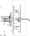
FIG. 2 is a schematic illustrating a configuration integrating a LWIR camera with a gas turbine engine in accordance with one or more embodiments of the present disclosure. -
FIG. 3 is a schematic illustrating an example configuration integrating a LWIR camera with a gas turbine engine in accordance with one or more embodiments of the present disclosure. -
FIG. 4 is a schematic illustrating a configuration utilizing a probe of a LWIR camera in accordance with one or more embodiments of the present disclosure. -
FIG. 5 illustrates a cross-sectional view taken along line A-A ofFIG. 1 in accordance with one or more embodiments of the present disclosure. -
FIG. 6 is a schematic illustrating a configuration utilizing a probe of a LWIR camera in accordance with one or more embodiments of the present disclosure. -
FIG. 7 is a schematic illustrating a configuration utilizing a probe of a LWIR camera in accordance with one or more embodiments of the present disclosure. -
FIG. 8 is a schematic illustrating a configuration utilizing a probe of a LWIR camera in accordance with one or more embodiments of the present disclosure. -
FIG. 9 is a schematic illustrating a configuration utilizing a probe of a LWIR camera in accordance with one or more embodiments of the present disclosure. -
FIG. 10 depicts an example of a control system in accordance with one or more embodiments of the present disclosure. -
FIG. 11 is a block diagram supportive of a camera positioning program in association with obtaining thermal measurements, in accordance with one or more embodiments of the present disclosure. -
FIG. 12 illustrates an example flowchart in accordance with one or more embodiments of the present disclosure. - A detailed description of one or more embodiments of the disclosed apparatus and method are presented herein by way of exemplification and not limitation with reference to the figures. According to one or more embodiments of the present disclosure, an actively driven remote mount LWIR Camera and techniques for mounting the LWIR camera are described which overcome the shortcomings of other approaches. Aspects of the LWIR camera described herein circumvent a reliance on a flexible mounting scheme by separating the gaspath casing mount (associated with the probe of the LWIR camera) and the fan duct mount (associated with the body of the LWIR camera).
- In accordance with one or more embodiments of the present disclosure, an LWIR camera is described in which the engine casing mount is disassociated or mechanically separate from the fan duct mount. In some aspects, the LWIR camera supports the transmission of an optical signal from the probe to the LWIR camera, over an air gap between the camera mount and the probe mount. In an example implementation, in view of the projection of the optical signal over the air gap, the LWIR camera includes shielding which overlaps the air gap and prevents the ingress of stray energy into the LWIR camera. In one or more embodiments, to mitigate misalignment concerns during operation of the LWIR camera, the LWIR camera is mounted on linear actuators (e.g., linear traverse rails) supportive of driving the LWIR camera along with the probe as the LWIR camera and the probe move independently.
- According to one or more embodiments of the present disclosure, the techniques described herein may incorporate a feedback loop associated with maintaining the alignment between the LWIR camera and the probe. In an example, photodetectors or infrared detectors are arrayed about the camera objective such that, based on a determined misalignment associated with the photodetectors or infrared detectors (e.g., should the alignment stray), a correction can be applied to the actuator schedule.
- In an example implementation, a control program may control the alignment of the LWIR camera and the probe according to an operation schedule of actuators of the gas turbine engine, in which the operation schedule is based on expected differential thermal excursion of the engine hardware. In some aspects, the control program may support an override to allow the photodetectors to correct should a misalignment occur. That is, for example, the control program may support correcting the alignment between the LWIR camera and the probe based on a misalignment detected using the photodetectors.
- Aspects of the present disclosure support additional and/or alternative techniques for positional correction and alignment of the LWIR camera and/or the probe. In an example, the control program may support implementing positional correction and alignment based on the image (e.g., image data) collected by the LWIR camera. Other non-limiting examples of feedback based on which the control program may implement positional correction and alignment include proximity measurements, strain measurements, and temperature measurements provided by corresponding hardware components. The techniques described herein include positional correction with respect to one or more axes (e.g., all three axes) using positional correction/alignment and feedback information as described herein.
- Particular aspects of the subject matter described herein may be implemented to realize an LWIR camera in which the separation of the engine casing mount from fan duct mounting mitigates differential thermal growth concerns. The example modularity features described herein support flexibility in positioning and improved repairability of the LWIR camera. In some aspects, the modularity features support mounting of the LWIR camera body at the outside of the gas turbine engine, which disassociates camera cooling requirements from the probe. Accordingly, for example, the modularity features support integration with the gas turbine engine for thermal imaging of the gas turbine engine, without relatively complex or heavy modifications to the structure of the gas turbine engine.
- The example modularity features and alignment features described herein support the realization of an LWIR camera capable of gathering thermal data associated with validating an airfoil design (e.g., airfoil thermal data on development engines), in which the time/cost integrating the LWIR camera with the development engines is reduced compared to other approaches. The techniques and LWIR camera described herein may be implemented in association with validating any suitable rotating hardware design (e.g., gas turbine engine, aircraft engines, and the like).
-
FIG. 1 schematically illustrates agas turbine engine 120. Thegas turbine engine 120 is disclosed herein as a two-spool turbofan that generally incorporates afan section 122, acompressor section 124, acombustor section 126 and aturbine section 128. Alternative engines might include other systems or features. Thefan section 122 drives air along a bypass flow path B in abypass duct 123, while thecompressor section 124 drives air along a core flow path C for compression and communication into thecombustor section 126 then expansion through theturbine section 128. Although depicted as a two-spool turbofan gas turbine engine in the disclosed non-limiting embodiment, it should be understood that the concepts described herein are not limited to use with two-spool turbofans as the teachings may be applied to other types of turbine engines including three-spool architectures. - With reference to
FIG. 1 , as used herein, "aft" refers to the direction associated with the tail (e.g., the back end) of an aircraft, or generally, to the direction of exhaust of the gas turbine engine (to the right inFIG. 1 ). The term "forward" refers to the direction associated with the nose (e.g., the front end) of an aircraft, or generally, to the direction of flight or motion (to the left inFIG. 1 ). - The
gas turbine engine 120 generally includes alow speed spool 130 and ahigh speed spool 132 mounted for rotation about an engine central longitudinal axis A relative to an enginestatic structure 136 via several bearingsystems 138. It should be understood that various bearingsystems 138 at various locations may alternatively or additionally be provided, and the location of bearingsystems 138 may be varied as appropriate to the application. - The
low speed spool 130 generally includes aninner shaft 140 that interconnects afan 142, a first orlow pressure compressor 144 and a first orlow pressure turbine 146. Theinner shaft 140 is connected to thefan 142 through a speed change mechanism, which ingas turbine engine 120 is illustrated as a gearedarchitecture 148 to drive thefan 142 at a lower speed than thelow speed spool 130. Thehigh speed spool 132 includes anouter shaft 150 that interconnects a second orhigh pressure compressor 152 and a second orhigh pressure turbine 154. Acombustor 156 is arranged ingas turbine engine 120 between thehigh pressure compressor 152 and thehigh pressure turbine 154. Amid-turbine frame 157 of the enginestatic structure 136 is arranged generally between thehigh pressure turbine 154 and thelow pressure turbine 146. Themid-turbine frame 157 furthersupports bearing systems 138 in theturbine section 128. Theinner shaft 140 and theouter shaft 150 are concentric and rotate via bearingsystems 138 about the engine central longitudinal axis A which is collinear with their longitudinal axes. - The core airflow is compressed by the
low pressure compressor 144 then thehigh pressure compressor 152, mixed and burned with fuel in thecombustor 156, then expanded over thehigh pressure turbine 154 andlow pressure turbine 146. Themid-turbine frame 157 includes airfoils which are in the core airflow path C. Theturbines low speed spool 130 andhigh speed spool 132 in response to the expansion. It will be appreciated that each of the positions of thefan section 122,compressor section 124,combustor section 126,turbine section 128, and fandrive gear system 148 may be varied. For example,gear system 148 may be located aft ofcombustor section 126 or even aft ofturbine section 128, andfan section 122 may be positioned forward or aft of the location ofgear system 148. - The
gas turbine engine 120 in one example is a high-bypass geared aircraft engine. In one non-limiting embodiment, the gearedarchitecture 148 is an epicyclic gear train, such as a planetary gear system or other gear system, with a gear reduction ratio. In one non-limiting embodiment, the fan diameter is significantly larger than that of thelow pressure compressor 144. The gearedarchitecture 148 may be an epicycle gear train, such as a planetary gear system or other gear system. It should be understood, however, that the above parameters are only examples embodiments of a geared architecture engine and that the present disclosure is applicable to other gas turbine engines including direct drive turbofans. A significant amount of thrust is provided by the bypass flow path B due to the high bypass ratio. - The
gas turbine engine 120 includes afan duct 160, anengine casing 165, and agaspath casing 170. Features of the gas turbine engine 120 (e.g., thefan duct 160,engine casing 165, and gaspath casing 170) are not necessarily drawn to scale, and shapes and positions thereof are not limited to the examples illustrated herein. In some aspects, thegas turbine engine 120 may be integrated with thefan 122 in a fan case assembly. - Example aspects of an
LWIR camera 200 which may be integrated with thegas turbine engine 120 in association with providing thermal imaging data (e.g., of a rotor blade located upstream or downstream of aprobe 220 of the LWIR camera 200) are described herein with reference to the following figures. In the examples described herein, theLWIR camera 200 may provide thermal imaging data of a rotor blade 159 (e.g., rotor blade 159-a, rotor blade 159-b) associated with thelow pressure turbine 146. TheLWIR camera 200 may also be referred to herein as a LWIR camera system, a thermal imaging device, a thermal imaging camera system, a thermal imaging system, or the like. -
FIG. 2 is a schematic illustrating a configuration integrating aLWIR camera 200 with agas turbine engine 120 in accordance with one or more embodiments of the present disclosure. In the example ofFIG. 2 , thegas turbine engine 120 includes thefan duct 160, theengine casing 165, and thegaspath casing 170 ofFIG. 1 . - The
LWIR camera 200 may include a main body 205 (also referred to herein as a housing). In the example ofFIG. 2 , themain body 205 is located outside of thegas turbine engine 120. According to one or more embodiments of the present disclosure, as themain body 205 is located outside thegas turbine engine 120, theLWIR camera 200 may be integrated with thegas turbine engine 120 without camera cooling (or with substantially less camera cooling compared to some other techniques). - The
main body 205 is mountable to surfaces of thegas turbine engine 120. For example, themain body 205 is mountable to the fan duct 160 (e.g., to an outer surface of the fan duct 160), as illustrated in the configuration ofFIG. 2 . Additionally, or alternatively, themain body 205 is mountable to a mounting structure separate from thefan duct 160, example aspects of which are later described with reference toFIG. 3 . - In an example, the
main body 205 may include or house acamera module 201 andprocessing circuitry 202 supportive of generating thermal images associated with thegas turbine engine 120. Themain body 205 may include orcontrol circuitry 204 supportive of movement control of the main body 205 (e.g., by controlling themotor 215 and/or the radial traverse 210). Additionally, or alternatively, theprocessing circuitry 202 and/or thecontrol circuitry 204 may be located outside of the main body 205 (e.g., included in a housing separate from the main body 205). - For example, to mitigate misalignment which may occur during operation of the LWIR camera 200 (e.g., due to movement or flexion of the
fan duct 160, theengine casing 165, themain body 205, and/or the probe 220), theLWIR camera 200 is mounted on linear actuators 211 (also referred to herein as linear traverse rails). Theprocessing circuitry 202 supports controlling the movement of the main body 205 (and camera module 201) along with theprobe 220, thereby maintaining alignment between the main body 205 (and camera module 201) and theprobe 220. For example, the processing circuitry 202 (and control circuitry 204) may support controlling movement of themain body 205 to compensate for any misalignment that may occur, as the physical separation of the main body 205 (and camera module 201) and theprobe 220 allows for themain body 205 and probe 220 to move independent of one another. Example aspects of feedback instrumentation utilized in association with maintaining the alignment are later described herein. - The
LWIR camera 200 includes aprobe 220. In some aspects, theprobe 220 is mountable to the engine casing 165 (e.g., to an outer surface of the casing 165). Theprobe 220 includes one ormore sensors 221 configured to detect thermal energy. - According to one or more embodiments of the present disclosure, the
main body 205 and theprobe 220 may be physically and mechanically separate. Theprobe 220 is configured to generate and transmit anoptical signal 223 based on the detected thermal energy. Theoptical signal 223 may include data representative of the detected thermal energy. For example, theoptical signal 223 may include measurement data associated with the detected thermal energy. - The
probe 220 may transmit theoptical signal 223 to themain body 205 over anair gap 207 between theprobe 220 and themain body 205. In an example, theair gap 207 is less than a distance between thefan duct 160 and theengine casing 165. - The optical design of the
LWIR camera 200 and theair gap 207 may accommodate a specific length from an end portion of the probe 220 (e.g., probe exit) to the entrance of theLWIR camera 200. For example, the length may be a distance between the end portion of theprobe 220 and the camera entrance of thecamera module 201. - In an example, the
probe 220 may transmit, and themain body 205 may receive, theoptical signal 223 via anaperture 206 of themain body 205. Theprocessing circuitry 202 is configured to provide temperature information in response to processing theoptical signal 223. - The
LWIR camera 200 includes a shieldingstructure 225. The shieldingstructure 225 may preclude stray energy from entering the main body 205 (and camera module 201). The shieldingstructure 225 may be coupled to themain body 205 and/or thefan duct 160. - In some aspects, the shielding
structure 225 may protrude through thefan duct 160 and extend in a direction (e.g., direction D2) perpendicular to thefan duct 160, towards theengine casing 165. According to one or more embodiments of the present disclosure, an inner area of the shielding structure 225 (e.g., defined with respect to a plane D1-D3) at least partially overlaps theaperture 206 of themain body 205. - According to one or more embodiments of the present disclosure, the thermal energy detected by the
probe 220 may be associated with a rotor blade 159 (e.g., rotor blade 159-a) of thegas turbine engine 120. - In the example configuration of
FIG. 2 , theprobe 220 is mounted to theengine casing 165 and extends across a secondary air cavity between theengine casing 165 and thegaspath casing 170. In an example, theprobe 220 at least partially protrudes through the gaspath casing 170 (e.g., in direction D2) and into a stator vane 158 (also referred to herein as an ingress stator vane or an ingress airfoil) of thegas turbine engine 120. - The
probe 220 may include areflective element 222 including a reflective surface. In some aspects, thereflective element 222 may relay light received at thereflective element 222 to thesensor 221. The example configuration is not limited to the positioning of elements described herein, and it is to be understood that thesensor 221 and thereflective element 222 of theprobe 220 may be positioned at different locations of theprobe 220. - In the example configuration, sensor 221 (e.g., if positioned at the end of the probe 220) and/or
reflective element 222 may be at least partially exposed (e.g., in direction D1, toward rotor blade 159-a) by an opening formed in thestator vane 158. Accordingly, for example, with reference toFIG. 2 , theprobe 220 may be capable of detecting thermal energy associated with rotor blade 159-a. In the example ofFIG. 2 , a rotor blade 159-b is adjacent thestator vane 158 but not included in the thermal measurement. - The
LWIR camera 200 may further include a gaseous nitrogen (GN2) cooling andpurge inlet 230. Thepurge inlet 230 may be coupled to or integrated with theprobe 220. TheLWIR camera 200 may further include a camera purge outlet 212 (e.g., capable of purging GN2 or air). - The
LWIR camera 200 may be a camera designed to measure infrared electromagnetic radiation practically defined as the 8 µm to 14 µm spectral band. TheLWIR camera 200 may includeadditional components 235. Theadditional components 235 may include, for example, a series of lens and mirrors including an optical system to focus and direct the infrared electromagnetic radiation. Additionally, or alternatively, theLWIR camera 200 may include an electrical system (not illustrated) to digitize, amplify, and transmit data signals representative of the infrared electromagnetic radiation to a data acquisition system. - According to one or more embodiments of the present disclosure, the
probe 220 may be implemented without optical fiber. For example, in one or more embodiments, theprobe 220 is absent any optical fiber and may support transmission of signals and light as described herein (e.g., data signals, infrared light, infrared signals, LWIR signals, and the like) without fiber optics. In one or more embodiments, one or more gaps between one or more lenses and/or one or more mirrors of theLWIR camera 200 may be air gaps. In some embodiments, all gaps between one or more lenses and/or one or more mirrors of theLWIR camera 200 may be air gaps. In some cases, use of the air gaps for signal and light transmission as described herein may provide advantages of improved reliability compared to transmission using fiber optics. Theprobe 220 may be referred to as an optical probe. - According to one or more embodiments of the present disclosure, the
LWIR camera 200 includes feedback instrumentation. The feedback instrumentation may be coupled to at least one of thefan duct 160, theengine casing 165, and theprobe 220. In some aspects, the feedback instrumentation is configured to provide electrical signals based on movement of at least one of thefan duct 160, theengine casing 165, and theprobe 220. - In an example, based on an electrical signal from the feedback instrumentation, the
control circuitry 204 may generate control signals associated with maintaining an alignment between themain body 205 and theprobe 220 based on the electrical signals. For example, thecontrol circuitry 204 may transmit a control signal toradial traverse 210 and/ormotor 215, thereby controlling themain body 205 to maintain alignment with theprobe 220. In some examples, thecontrol circuitry 204 may transmit the control signal in association with controlling themain body 205 to maintain the air gap 207 (e.g., maintain a target distance between themain body 205 and the probe 220). In some embodiments, the target distance of theair gap 207 may be in a range of about 6 inches (152mm) to about 12 inches (304mm). However, embodiments of the present disclosure are not limited thereto, and target distance of theair gap 207 may be a distance suitable for signal and light transmission between theprobe 220 and the main body 205 (e.g., camera components included in the main body 205). - Additionally, or alternatively, based on an electrical signal from the feedback instrumentation, the
control circuitry 204 may generate and provide, to thecamera module 201, control signals associated with adjusting parameters (e.g., image capture parameters) of thecamera module 201. Non-limiting examples of the feedback instrumentation are later described herein. - In the examples described herein, the
stator vane 158 and therotor blade 159 are associated withlow pressure compressor 144 of thegas turbine engine 120. However, embodiments supported by the present disclosure are not limited thereto. For example, aspects of the present disclosure support measuring thermal energy associated with other components of the gas turbine engine 120 (e.g., a rotor blade associated withlow pressure turbine 146,high pressure compressor 152, or high pressure turbine 154). -
FIG. 3 is a schematic illustrating anexample configuration 300 integrating theLWIR camera 200 with agas turbine engine 120 in accordance with one or more embodiments of the present disclosure. Repeated descriptions of theLWIR camera 200 and thegas turbine engine 120 are omitted for brevity. - In the example configuration of
FIG. 3 , themain body 205 is mounted to a mountingstructure 240. The mountingstructure 240 may be physically separate from thefan duct 160. For example, the mountingstructure 240 may be a camera mount support fixed to an object or surface different from thefan duct 160. In an example, the mountingstructure 240 may be fixed to the ground, a stationary cart, or the like. -
Slider seal 242 includes an annular disc, either metallic or composite, entrapped within a housing. This arrangement provides flow discouragement without limiting translation or rotation of a cylindrical component passing thru the center of the annulus. -
FIG. 4 is a schematic illustrating aconfiguration 400 utilizing a probe 220-b of theLWIR camera 200 in accordance with one or more embodiments of the present disclosure. The probe 220-b includes aspects of theprobe 220 described herein (e.g., with reference toFIGS. 2 and3 ), and repeated descriptions of like elements are omitted for brevity. Repeated descriptions of theLWIR camera 200 and thegas turbine engine 120 are omitted for brevity. - Referring to
FIG. 4 ,sensor 221 faces in a direction (e.g., direction D2) perpendicular to thegaspath casing 170 and toward the rotor blade 159-a. The probe 220-b protrudes through an opening of thegaspath casing 170, enabling thesensor 221 to detect thermal energy associated with the rotor blade 159-a. As illustrated in the example ofFIG. 4 , the probe 220-b may be implemented without thereflective element 222 ofFIG. 1 , as thesensor 221 may face directly toward the rotor blade 159-a. As described with reference toFIG. 4 , probe 220-b is a radial viewing probe facing inboard at a target airfoil (e.g., rotor blade 159-a) thru a case mounted objective. -
FIG. 5 illustrates across-sectional view 500 taken along line A-A ofFIG. 1 . Thecross-sectional view 500 is a plan view including thefan duct 160 and a sensing face 501 of theprobe 220, positioned with respect to anengine centerline 515 of thegas turbine engine 120. The sensing face 501 may be exposed by anopening 510 formed in thefan duct 160. The sensing face 501 may be located at an end portion of theprobe 220. - An example of feedback instrumentation (e.g., photodetectors 505) supportive of maintaining or correcting an alignment between the
LWIR camera 200 and theprobe 220 in accordance with one or more embodiments of the present disclosure is described herein with reference toFIG. 5 . - The
photodetectors 505 may be located at an end portion (e.g., at sensing face 501) of theprobe 220. Thephotodetectors 505 may be configured to generate electrical signals in response to detecting emitted light of an infrared band. In an example, theLWIR camera 200 may include an emitter (emission device) integrated with and/or housed in themain body 205, and the emitter may be configured to emit the light of the infrared band. In some examples, the infrared band is a long-wave IR (LWIR) band. For example, the light emitted by the emitter may have a wavelength ranging from 8µm to 14µm. - The example aspects of the
photodetectors 505 and the emitter are not limited to the example wavelengths and frequency bands described herein. For example, aspects of the present disclosure support implementations using other suitable wavelengths or frequency bands associated with inspecting thegas turbine engine 120. - The
photodetectors 505 may provide data indicative of real-time relative movements between the probe 220 (and thereby the engine casing 165) and themain body 205 according to 3 axes (e.g., with respect to the D1, D2, and D3 directions). Based on electrical signals from photodetectors 505 (e.g., as generated in response to energy detected by the photodetectors 505), theprocessing circuitry 202 and/orcontrol circuitry 204 may generate and provide control signals toradial traverse 210,motor 215, and/orcamera module 201 as described herein. - In the example of
FIG. 5 , the probe 220 (and sensing face 501) includes fourphotodetectors 505, but aspects of the present disclosure are not limited thereto. For example, theprobe 220 may include any suitable quantity and/or configuration ofphotodetectors 505 for maintaining or correcting an alignment between theLWIR camera 200 and theprobe 220. -
FIG. 6 is a schematic illustrating aconfiguration 600 utilizingprobe 220 of theLWIR camera 200 in accordance with one or more embodiments of the present disclosure. Repeated descriptions of theLWIR camera 200 and thegas turbine engine 120 are omitted for brevity. Some identifiers associated with components of theLWIR camera 200 and thegas turbine engine 120 are omitted so as not to obstruct from the discussion ofFIG. 6 . - An example of feedback instrumentation (e.g., proximity probes 605) supportive of maintaining or correcting an alignment between the
LWIR camera 200 and theprobe 220 in accordance with one or more embodiments of the present disclosure is described herein with reference toFIG. 6 . - The feedback instrumentation includes proximity probes 605 coupled to the
fan duct 160. In the example ofFIG. 6 , proximity probe 605-a is coupled to a probe bracket 610-a, proximity probe 605-b is coupled to a probe bracket 610-b, and the probe bracket 610-a and probe bracket 610-b are coupled to (e.g., rigidly mounted to) thefan duct 160. The feedback instrumentation further includes a target structure 615-a and a target structure 615-b coupled to (e.g., rigidly mounted to) theengine casing 165. However, aspects of the present disclosure not limited thereto. For example, a probe bracket 610 (and corresponding proximity probe 605) may be coupled to theengine casing 165, and acorresponding target structure 615 may be coupled to thefan duct 160. In another example, both probe brackets 610 (and corresponding proximity probes 605) may be coupled to theengine casing 165, and both targetstructures 615 may be coupled to thefan duct 160. - The proximity probes 605 may provide data indicative of real-time relative movements between the
fan duct 160 andengine casing 165 according to 3 axes (e.g., with respect to the D1, D2, and D3 directions). For example, proximity probe 605-a is capable of providing radial measurements. In another example, proximity probe 605-b is capable of providing axial measurements. In some aspects, proximity probe 605-b may be rotated 90 degrees to provide tangential deflection measurements. - The proximity probes 605 may provide electrical signals indicative of the radial measurements, axial measurements, and/or tangential deflection measurements to the
processing circuitry 202 and/orcontrol circuitry 204. Based on the electrical signals from the proximity probes 605, theprocessing circuitry 202 and/orcontrol circuitry 204 may generate and provide control signals toradial traverse 210,motor 215, and/orcamera module 201 as described herein. -
FIG. 7 is a schematic illustrating aconfiguration 700 utilizingprobe 220 of theLWIR camera 200 in accordance with one or more embodiments of the present disclosure. Repeated descriptions of theLWIR camera 200 and thegas turbine engine 120 are omitted for brevity. Some identifiers associated with components of theLWIR camera 200 and thegas turbine engine 120 are omitted so as not to obstruct from the discussion ofFIG. 7 . - An example of feedback instrumentation (e.g., linear variable differential transformers (LVDTs) 705) supportive of maintaining or correcting an alignment between the
LWIR camera 200 and theprobe 220 in accordance with one or more embodiments of the present disclosure is described herein with reference toFIG. 7 . EachLVDT 705 is an electromechanical transducer capable of converting motion of an object (e.g., aduct side mount 710, a case side mount 715) to which theLVDTs 705 is coupled mechanically into a corresponding electrical signal. - For example, the feedback instrumentation includes
LVDTs 705 coupled to thefan duct 160 and theengine casing 165. In the example ofFIG. 7 , LVDT 705-a is coupled to a duct side mount 710-a and a case side mount 715-a, and LVDT 705-b is coupled to a duct side mount 710-b and a case side mount 715-b. The duct side mount 710-a and duct side mount 710-b are coupled to (e.g., rigidly mounted to) thefan duct 160, and the case side mount 715-a and case side mount 715-b are coupled to (e.g., rigidly mounted to) theengine casing 165. - The
LVDTs 705 may provide data indicative of real-time relative movements between thefan duct 160 andengine casing 165 according to 3 axes (e.g., with respect to the D1, D2, and D3 directions). For example, LVDT 705-a is capable of providing radial measurements. In another example, LVDT 705-b is capable of providing axial measurements. In some aspects, LVDT 705-b may be rotated 90 degrees to provide tangential deflection measurements. - The
LVDTs 705 may provide electrical signals indicative of the radial measurements, axial measurements, and/or tangential deflection measurements to theprocessing circuitry 202 and/orcontrol circuitry 204. Based on the electrical signals from theLVDTs 705, theprocessing circuitry 202 and/orcontrol circuitry 204 may generate and provide control signals toradial traverse 210,motor 215, and/orcamera module 201 as described herein. -
FIG. 8 is a schematic illustrating aconfiguration 800 utilizingprobe 220 of theLWIR camera 200 in accordance with one or more embodiments of the present disclosure. Repeated descriptions of theLWIR camera 200 and thegas turbine engine 120 are omitted for brevity. Some identifiers associated with components of theLWIR camera 200 and thegas turbine engine 120 are omitted so as not to obstruct from the discussion ofFIG. 8 . - An example of feedback instrumentation (e.g., strain gages 805) supportive of maintaining or correcting an alignment between the
LWIR camera 200 and theprobe 220 in accordance with one or more embodiments of the present disclosure is described herein with reference toFIG. 8 . Eachstrain gage 805 is a sensor having a resistance which varies with applied force. For example, eachstrain gage 805 is coupled to anelastic member 810 and converts force, pressure, tension, or the like associated with theelastic member 810 into a change in electrical resistance. - For example, the feedback instrumentation includes elastic member 810-a and elastic member 810-b each coupled to (e.g., rigidly mounted to) the
fan duct 160 and theengine casing 165. In the example ofFIG. 8 , strain gage 805-a is coupled to elastic member 810-a, and strain gage 805-b is coupled to elastic member 810-b. - The strain gages 805 may provide data indicative of real-time relative movements between the
fan duct 160 andengine casing 165 according to 3 axes (e.g., with respect to the D1, D2, and D3 directions). For example, strain gage 805-a is capable of providing electrical resistance measurements (or changes in electrical resistance) that correspond to radial movement/measurements. In another example, strain gage 805-b is capable of providing electrical resistance measurements (or changes in electrical resistance) that correspond to axial movement/measurements. In some aspects, strain gage 805-b may be rotated 90 degrees to provide tangential deflection movement/measurements. - The strain gages 805 may provide electrical signals indicative of the electrical resistance measurements (which correspond to radial, axial, and/or tangential deflection movement/measurements) to the
processing circuitry 202 and/orcontrol circuitry 204. Based on the electrical signals from thestrain gages 805, theprocessing circuitry 202 and/orcontrol circuitry 204 may generate and provide control signals toradial traverse 210,motor 215, and/orcamera module 201 as described herein. -
FIG. 9 is a schematic illustrating aconfiguration 900 utilizingprobe 220 of theLWIR camera 200 in accordance with one or more embodiments of the present disclosure. Repeated descriptions of theLWIR camera 200 and thegas turbine engine 120 are omitted for brevity. Some identifiers associated with components of theLWIR camera 200 and thegas turbine engine 120 are omitted so as not to obstruct from the discussion ofFIG. 9 . - An example of feedback instrumentation (e.g.,
thermocouple 905, thermocouple 910) supportive of maintaining or correcting an alignment between theLWIR camera 200 and theprobe 220 in accordance with one or more embodiments of the present disclosure is described herein with reference toFIG. 8 . The thermocouples (e.g.,thermocouple 905, thermocouple 910) described herein may be metal thermocouples which may be used to provide real-time relative movements between thefan duct 160 andengine casing 165 in the axial direction. - Each
thermocouple 905 is capable of determining temperature at a location on thefan duct 160 to which thethermocouple 905 is coupled, and eachthermocouple 910 is capable of determining temperature at a location on theengine casing 165 to which thethermocouple 910 is coupled. In the example ofFIG. 9 , the feedback instrumentation includes a series ofthermocouples 905 along thefan duct 160 and a series ofthermocouples 910 along theengine casing 165. - The
thermocouples 905 andthermocouples 910 may provide electrical signals indicative of the determined temperatures to theprocessing circuitry 202 and/orcontrol circuitry 204. Based on the electrical signals from thethermocouples 905 andthermocouples 910, theprocessing circuitry 202 and/orcontrol circuitry 204 may determine average temperatures of thefan duct 160 and/or theengine casing 165, thermal growth associated with thefan duct 160 and/or theengine casing 165, and accordingly, relative deflection of thefan duct 160 and/or theengine casing 165. Based on the relative deflection, theprocessing circuitry 202 and/orcontrol circuitry 204 may determine relative position of theprobe 220 to themain body 205, and accordingly, generate and provide control signals toradial traverse 210,motor 215, and/orcamera module 201 as described herein. -
FIG. 10 depicts an example of acontrol system 1000 in accordance with one or more embodiments of the present disclosure. Thecontrol system 1000 is configured to monitor and control operation of a gas turbine engine (e.g., the gas turbine engine 120) and/or theLWIR camera 200 in real-time (or near-real time) according to one or more embodiments described herein. - In some embodiments, the
control system 1000 performs the functionality of a data acquisition system by receiving, processing, storing and/or reporting data received from feedback instrumentation 1005 (e.g.,photodetectors 505, proximity probes 605,LVDTs 705,strain gages 805,thermocouples 905, and the like described herein). Thecontrol system 1000 can control functions of thegas turbine engine 120 and/or theLWIR camera 200 by generating one or more commands. - The control system 1000 (also referred to as a "controller") can be a full authority digital engine control (FADEC) that includes processing circuitry 1015 (also referred to as a "processing device"),
control circuitry 1020, and a memory system 1025 (also referred to as a "memory") configured to store a plurality of configuration items, where at least one of the configuration items includes a sequence of the computer executable instructions for execution by theprocessing circuitry 1015. Other types of configuration items can include data, such as constants, configurable data, and/or fault data. Examples of computer executable instructions can include boot software, operating system software, and/or application software. The executable instructions may be stored or organized in any manner and at any level of abstraction, such as in connection with controlling and/or monitoring operation of thegas turbine engine 120. Theprocessing circuitry 1015 can be any type or combination of central processing unit (CPU), including one or more of a microprocessor, a digital signal processor (DSP), a microcontroller, an application specific integrated circuit (ASIC), a field programmable gate array (FPGA), or the like. Also, in embodiments, thememory system 1025 may include volatile memory, such as random access memory (RAM), and non-volatile memory, such as Flash memory, read only memory (ROM), and/or other electronic, optical, magnetic, or any other computer readable medium onto which is stored data and algorithms in a non-transitory form. - The
control system 1000 can also include one or more of an input/output interface 1035, acommunication interface 1030, and/or other elements. The input/output interface 1035 can include support circuitry for interfacing with the LWIR camera 200 (e.g.,camera module 201,processing circuitry 202,control circuitry 204, probe 220) andfeedback instrumentation 1005, such as filters, amplifiers, digital-to-analog converters, analog-to-digital converters, and other such circuits to support digital and/or analog interfaces. Further, the input/output interface 1035 can receive or output signals to/from other sources, such as discrete inputs/outputs and/or status signals. - The
communication interface 1030 may communicate with an aircraft bus 1040 of an aircraft. The aircraft bus 1040 can provide aircraft-level parameters and commands that are used by thecontrol system 1000 to control thegas turbine engine 120 in real-time. Thecommunication interface 1030 may also support communication with other components, such as other instances of thecontrol system 1000, storage units, diagnostic units, communication adapters, off-board systems, and the like. For example, thecommunication interface 1030 may support communication with a computing device 1045 (e.g., an aircraft testing computer, an aircraft maintenance computer, or the like) to provide for communication between (e.g., transmitting commands/data to and/or receiving commands/data from) thecontrol system 1000 and thecomputing device 1045. - The
control system 1000 provides for, among other things, monitoring thegas turbine engine 120 based on data collected by the LWIR camera 200 (e.g.,camera module 201, probe 220) andfeedback instrumentation 1005. Thegas turbine engine 120 is one example of an aircraft engine, and other examples are also possible, such as hybrid electric turbine engines. It may be desirable to monitor properties of thegas turbine engine 120, such as temperature, pressure, flow rate, etc. to detect problems, such as anomalies, with thegas turbine engine 120. -
FIG. 11 is a block diagram 1100 supportive of a camera positioning program 1101 (e.g., maintaining or correcting alignment between aLWIR camera 200 and a probe 220) in association with obtaining thermal measurements, in accordance with one or more embodiments of the present disclosure. Aspects the features described with reference to block diagram 1100 may be implemented by the example aspects ofcontrol system 1000 as described herein. -
Base program 1105 includes configurations supportive of a defined analytical use case (e.g., expected case and expected duct excursions). - The
camera positioning program 1101 includes a feedback loop incorporatinginput data 1110 from feedback instrumentation (e.g.,photodetectors 505, proximity probes 605,LVDTs 705,strain gages 805, thermocouples 905) described herein. Based on the data from the feedback instrumentation, thecamera positioning program 1101 provides correction (at 1115) to thebase program 1105. For example, The correction to the base program may address uncertainty or errors in the analytical predictions. In an example, if the fan ducting excursion lags the engine casing excursion by more than predicted, the signal exiting theprobe 220 may become misaligned with the camera objective, which may result in a potential loss of signal/measurement/data collection. Through the use of one or more of the feedback instrumentation systems described herein, thecamera positioning program 1101 may provide real-time correction for the misalignment and mitigate the aforementioned shortfall. In one or more embodiments, thecamera positioning program 1101 may define distance 'x' over time period 't' and a correction factor 'f', in which the correction factor 'f' is added to 'x' over the same time period 't'. Accordingly, for example, thecamera positioning program 1101 may provide a driving function of (x+f)/t = position of theLWIR camera 200. - In one or more embodiments, the
camera positioning program 1101 may alternatively and/or additionally incorporatefeedback 1112 from theLWIR camera 200 for positional correction. For example, thefeedback 1112 may include data indicating whether an image is out of focus and/or data indicating positioning adjustments for adjusting the focus, and thecamera positioning program 1101 may provide correction (at 1115) to thebase program 1105 based on thefeedback 1112. Thecamera positioning program 1101 may provide a camera positioning output 1120 (e.g., positioning commands for the LWIR camera 200) based on thebase program 1105 and the correction as provided at 1115. - Aspects of the present disclosure support utilizing feedback from feedback instrumentation other than that described herein. Other non-limiting examples of feedback instrumentation include capacitance probes, Eddy current probes, or the like. In one or more embodiments, the
camera positioning program 1101 may incorporate feedback from one or more sources (e.g.,photodetectors 505, proximity probes 605, and the like described herein) based on which to provide correction associated with thebase program 1105 and/or camera positioning. -
FIG. 12 illustrates an example flowchart of amethod 1200 of controlling a thermal imaging device (e.g., LWIR camera 200) for a gas turbine engine in accordance with one or more embodiments of the present disclosure. Themethod 1200 may be implemented by the example aspects of aLWIR camera 200 and/or acontrol system 1010 as described herein. - At 1205, the method includes detecting, by a probe of a thermal imaging device, thermal energy associated with a gas turbine engine.
- At 1210, the method includes transmitting, by the probe, an optical signal based on detected thermal energy associated with the gas turbine engine, wherein the optical signal is transmitted to an aperture of a main body of the thermal imaging device, over an air gap between the probe and the main body.
- At 1215, the method includes providing temperature information associated with the gas turbine engine in response to processing the optical signal.
- In addition to one or more of the features described herein, or as an alternative to any of the embodiments, the method includes generating, by control circuitry, one or more control signals associated with maintaining the air gap between an end portion of the probe and the main body.
- In addition to one or more of the features described herein, or as an alternative to any of the embodiments, a target distance of the air gap is in a range of about 6 inches (152mm) to about 12 inches (304mm).
- In addition to one or more of the features described herein, or as an alternative to any of the embodiments, the method includes generating, by control circuitry, one or more control signals associated with maintaining an alignment between the probe and the main body.
- In addition to one or more of the features described herein, or as an alternative to any of the embodiments, the method includes emitting, by an emitter integrated with the main body, light of an infrared (IR) band; generating, by a set of photodetectors located at an end portion of the probe, an electrical signal in response to detecting the emitted light; and generating, by control circuitry, one or more control signals associated with positioning the main body based on the electrical signal.
- In addition to one or more of the features described herein, or as an alternative to any of the embodiments, the IR band is a long-wave IR band.
- In the descriptions of the flowcharts herein, the operations may be performed in a different order than the order shown, or the operations may be performed in different orders or at different times. Certain operations may also be left out of the flowcharts, one or more operations may be repeated, or other operations may be added to the flowcharts.
- The term "about" is intended to include the degree of error associated with measurement of the particular quantity based upon the equipment available at the time of filing the application. For example, "about" can include a range of ± 8% or 5%, or 2% of a given value.
- The terminology used herein is for the purpose of describing particular embodiments only and is not intended to be limiting of the present disclosure. As used herein, the singular forms "a", "an" and "the" are intended to include the plural forms as well, unless the context clearly indicates otherwise. It will be further understood that the terms "comprises" and/or "comprising," when used in this specification, specify the presence of stated features, integers, steps, operations, elements, and/or components, but do not preclude the presence or addition of one or more other features, integers, steps, operations, element components, and/or groups thereof.
- While the present disclosure has been described with reference to an embodiment or embodiments, it will be understood by those skilled in the art that various changes may be made and equivalents may be substituted for elements thereof without departing from the scope of the present disclosure. In addition, many modifications may be made to adapt a particular situation or material to the teachings of the present disclosure without departing from the essential scope thereof. Therefore, it is intended that the present disclosure not be limited to the particular embodiment disclosed as the best mode contemplated for carrying out this present disclosure, but that the present disclosure will include all embodiments falling within the scope of the claims.
Claims (15)
- A gas turbine engine comprising:a fan duct (160);an engine casing (165); anda gaspath casing (170), wherein a thermal imaging device (200) is integrated with the gas turbine engine (120), the thermal imaging device (200) comprising:a main body (205) comprising processing circuitry, wherein the main body (205) is mountable to the fan duct (160) or a mounting structure (240) separate from the fan duct (160); anda probe (220) mounted to the engine casing (165), wherein:the probe (220) comprises one or more sensors (221) configured to detect thermal energy; andthe probe (220) is configured to transmit an optical signal based on the detected thermal energy, to an aperture (206) of the main body (205), over an air gap (207) between the probe (220) and the main body (205), wherein the processing circuitry (202) is configured to provide temperature information in response to processing the optical signal.
- The gas turbine engine of claim 1, wherein the thermal imaging device (200) further comprises control circuitry (204) configured to generate one or more control signals associated with maintaining the air gap (207) between an end portion of the probe (220) and the main body (205).
- The gas turbine engine of claim 1 or 2, wherein a target distance of the air gap (207) is in a range of about 6 inches (152mm) to about 12 inches (304mm).
- The gas turbine engine of any preceding claim, wherein the thermal imaging device (200) further comprises control circuitry (204) configured to generate one or more control signals associated with maintaining an alignment between the probe (220) and the main body (205).
- The gas turbine engine of any preceding claim, wherein the thermal imaging device (200) further comprises feedback instrumentation, wherein the feedback instrumentation comprises:an emitter integrated with the main body (205) and configured to emit light of an infrared band;a set of photodetectors (505) located at an end portion of the probe (220) and configured to generate an electrical signal in response to detecting the emitted light; andcontrol circuitry (204) configured to generate, based on the electrical signal, one or more control signals associated with positioning the main body (205), optionally wherein the infrared band is a long-wave infrared band.
- The gas turbine engine of any preceding claim, wherein:the probe (220) at least partially protrudes through and is mounted to the gaspath casing (170); andthe one or more sensors (221) face in a direction toward a rotor blade (159) of the gas turbine engine (120).
- The gas turbine engine of any preceding claim, wherein the main body (205) is located outside of the gas turbine engine (120).
- The gas turbine engine of any preceding claim, wherein:the thermal imaging device (200) further comprises a shielding structure (225) coupled to the main body (205) and/or the fan duct (160); and/orthe thermal imaging device (200) further comprises a motor (215) configured to position the main body (205) based on one or more control signals generated by control circuitry (204) of the thermal imaging device (200).
- The gas turbine engine of any preceding claim, wherein:the gas turbine engine (120) further comprises a low pressure compressor (144), a low pressure turbine (146), a high pressure compressor (152), and a high pressure turbine (154); andthe thermal energy is associated with at least one of the low pressure compressor (144), the low pressure turbine (146), the high pressure compressor (152), and the high pressure turbine (154).
- The gas turbine engine of any preceding claim, wherein the gas turbine engine (120) is a prototype gas turbine engine (120).
- A method of controlling a thermal imaging device (200) for a gas turbine engine, comprising:detecting, by a probe (220) of the thermal imaging device (200), thermal energy associated with the gas turbine engine (120);transmitting, by the probe (220), an optical signal based on detected thermal energy associated with the gas turbine engine (120), wherein the optical signal is transmitted to an aperture (206) of a main body (205) of the thermal imaging device (200), over an air gap (207) between the probe (220) and the main body (205); andproviding temperature information associated with the gas turbine engine (120) in response to processing the optical signal.
- The method of claim 11, further comprising generating, by control circuitry (204), one or more control signals associated with maintaining the air gap (207) between an end portion of the probe (220) and the main body (205).
- The method of claim 11 or 12, wherein a target distance of the air gap (207) is in a range of about 6 inches (152mm) to about 12 inches (304mm).
- The method of claim 11, 12 or 13, further comprising generating, by a or the control circuitry (204), one or more control signals associated with maintaining an alignment between the probe (220) and the main body (205).
- The method of any of claims 11 to 14, further comprising:emitting, by an emitter integrated with the main body (205), light of an infrared band;generating, by a set of photodetectors (505) located at an end portion of the probe (220), an electrical signal in response to detecting the emitted light; andgenerating, by a or the control circuitry (204), one or more control signals associated with positioning the main body (205) based on the electrical signal, optionally wherein the infrared band is a long-wave infrared band.
Applications Claiming Priority (1)
| Application Number | Priority Date | Filing Date | Title |
|---|---|---|---|
| US18/499,937 US12535015B2 (en) | 2023-11-01 | 2023-11-01 | Actively driven remote mount optical probe |
Publications (1)
| Publication Number | Publication Date |
|---|---|
| EP4549706A1 true EP4549706A1 (en) | 2025-05-07 |
Family
ID=93291706
Family Applications (1)
| Application Number | Title | Priority Date | Filing Date |
|---|---|---|---|
| EP24209289.8A Pending EP4549706A1 (en) | 2023-11-01 | 2024-10-28 | Actively driven remote mount optical probe |
Country Status (2)
| Country | Link |
|---|---|
| US (1) | US12535015B2 (en) |
| EP (1) | EP4549706A1 (en) |
Citations (3)
| Publication number | Priority date | Publication date | Assignee | Title |
|---|---|---|---|---|
| US4836689A (en) * | 1986-02-27 | 1989-06-06 | Rosemount Inc. | Asymmetric purge air system for cleaning a lens |
| US20150346032A1 (en) * | 2014-06-03 | 2015-12-03 | Siemens Energy, Inc. | Dual infrared band apparatus and method for thermally mapping a component in a high temperature combustion environment |
| CA2959669A1 (en) * | 2016-03-17 | 2017-09-17 | General Electric Company | Optical imaging system for a gas turbine engine |
Family Cites Families (15)
| Publication number | Priority date | Publication date | Assignee | Title |
|---|---|---|---|---|
| US6364524B1 (en) | 1998-04-14 | 2002-04-02 | Advanced Fuel Research, Inc | High speed infrared radiation thermometer, system, and method |
| US7484413B2 (en) | 2003-12-12 | 2009-02-03 | The Boeing Company | Remote radius inspection tool for composite joints |
| US6992315B2 (en) | 2004-03-10 | 2006-01-31 | Siemens Westinghouse Power Corporation | In situ combustion turbine engine airfoil inspection |
| US8544279B2 (en) * | 2005-11-04 | 2013-10-01 | Zolo Technologies, Inc. | Method and apparatus for spectroscopic measurements in the combustion zone of a gas turbine engine |
| GB0816728D0 (en) * | 2008-09-15 | 2008-10-22 | Rolls Royce Plc | Improvements in or relating to engine monitoring and control |
| US10704958B2 (en) * | 2010-10-21 | 2020-07-07 | Siemens Energy, Inc. | Method for monitoring a high-temperature region of interest in a turbine engine |
| CA2799869C (en) * | 2012-12-20 | 2019-08-20 | General Electric Company | System and method for determining location data for pipes in a steam generator |
| US10041371B1 (en) | 2015-02-06 | 2018-08-07 | Siemens Energy, Inc. | In-situ measurement of blade tip-to-shroud gap in turbine engine |
| DE102016116359B4 (en) * | 2015-09-03 | 2024-02-15 | Siemens Energy, Inc. | METHOD AND SYSTEM FOR DETERMINING THE DISTRIBUTION OF TEMPERATURE AND SPEED IN A GAS TURBINE ENGINE |
| US10815817B2 (en) * | 2016-01-21 | 2020-10-27 | Raytheon Technologies Corporation | Heat flux measurement system |
| US10473528B2 (en) | 2016-02-13 | 2019-11-12 | General Electric Company | Optical apparatus and sight tube for inspecting turbine engine components |
| US20170234772A1 (en) | 2016-02-13 | 2017-08-17 | General Electric Company | Optical imaging system for inspecting turbine engine components and method for operating same |
| US10920590B2 (en) * | 2016-06-30 | 2021-02-16 | General Electric Company | Turbine assembly maintenance methods |
| US20190383158A1 (en) * | 2018-06-14 | 2019-12-19 | General Electric Company | Probe Motion Compensation |
| FR3082687B1 (en) * | 2018-06-18 | 2021-10-01 | Safran Nacelles | DEVICE AND METHOD FOR COMMUNICATION OF DATA IN AN AIRCRAFT SUB-ASSEMBLY |
-
2023
- 2023-11-01 US US18/499,937 patent/US12535015B2/en active Active
-
2024
- 2024-10-28 EP EP24209289.8A patent/EP4549706A1/en active Pending
Patent Citations (3)
| Publication number | Priority date | Publication date | Assignee | Title |
|---|---|---|---|---|
| US4836689A (en) * | 1986-02-27 | 1989-06-06 | Rosemount Inc. | Asymmetric purge air system for cleaning a lens |
| US20150346032A1 (en) * | 2014-06-03 | 2015-12-03 | Siemens Energy, Inc. | Dual infrared band apparatus and method for thermally mapping a component in a high temperature combustion environment |
| CA2959669A1 (en) * | 2016-03-17 | 2017-09-17 | General Electric Company | Optical imaging system for a gas turbine engine |
Also Published As
| Publication number | Publication date |
|---|---|
| US12535015B2 (en) | 2026-01-27 |
| US20250137385A1 (en) | 2025-05-01 |
Similar Documents
| Publication | Publication Date | Title |
|---|---|---|
| Cosentino et al. | Harps-N: the new planet hunter at TNG | |
| US11346239B2 (en) | Heat flux measurement system | |
| CN111279181B (en) | Apparatus and method for optically monitoring a moving component | |
| US20090285259A1 (en) | System and method for thermal inspection of objects | |
| KR20130118885A (en) | Method for monitoring a high-temperature region of interest in a turbine engine | |
| US20050237519A1 (en) | Method and apparatus for in situ inspection of reformer tubes | |
| US20130235391A1 (en) | One-dimensional coherent fiber array for inspecting components in a gas turbine engine | |
| EP2447687A1 (en) | Smart radiation thermometry system for real time gas turbine control and prognosis | |
| WO2019022852A1 (en) | Blade vibration monitor with self adjusting sensor gap mechanism | |
| EP1154252A1 (en) | Temperature measuring system and optical switch used therein | |
| CN120867849B (en) | Systems and methods using tool components | |
| JP5133523B2 (en) | Radiographic inspection of aircraft and other large objects | |
| EP2642085B1 (en) | An inspection device for a gas turbine engine | |
| EP4549706A1 (en) | Actively driven remote mount optical probe | |
| US20150346032A1 (en) | Dual infrared band apparatus and method for thermally mapping a component in a high temperature combustion environment | |
| EP2759819A1 (en) | Multi-color pyrometry imaging system and method of operating the same | |
| EP3744951A1 (en) | Proximity vane angle measurement | |
| US9250136B1 (en) | Hyperspectral imaging system for pyrometry applications and method of operating the same | |
| EP4134643A1 (en) | Non-contact high temperature measurement system | |
| Satish et al. | Investigation into the development and testing of a simplex capacitance sensor for rotor tip clearance measurement in turbo machinery | |
| Vishwanatha Rao et al. | Challenges in engine health monitoring instrumentation during developmental testing of gas turbine engines | |
| EP4112886B1 (en) | In-flight measured propulsion mass flow and thrust on aircraft | |
| US20230167750A1 (en) | Gimbal Systems, Apparatus, Articles of Manufacture and Associated Methods | |
| US9857227B1 (en) | Flash thermography device having moveable arm for inspecting internal turbine components | |
| Mitsch et al. | Versatile multi-object spectroscopy with FORS at the ESO Very Large Telescope |
Legal Events
| Date | Code | Title | Description |
|---|---|---|---|
| PUAI | Public reference made under article 153(3) epc to a published international application that has entered the european phase |
Free format text: ORIGINAL CODE: 0009012 |
|
| STAA | Information on the status of an ep patent application or granted ep patent |
Free format text: STATUS: THE APPLICATION HAS BEEN PUBLISHED |
|
| AK | Designated contracting states |
Kind code of ref document: A1 Designated state(s): AL AT BE BG CH CY CZ DE DK EE ES FI FR GB GR HR HU IE IS IT LI LT LU LV MC ME MK MT NL NO PL PT RO RS SE SI SK SM TR |
|
| STAA | Information on the status of an ep patent application or granted ep patent |
Free format text: STATUS: REQUEST FOR EXAMINATION WAS MADE |
|
| 17P | Request for examination filed |
Effective date: 20251106 |