EP4549694A1 - Enhancing drilling accuracy for a mobile underground drilling rig, and related devices, methods and computer programs - Google Patents
Enhancing drilling accuracy for a mobile underground drilling rig, and related devices, methods and computer programs Download PDFInfo
- Publication number
- EP4549694A1 EP4549694A1 EP23206959.1A EP23206959A EP4549694A1 EP 4549694 A1 EP4549694 A1 EP 4549694A1 EP 23206959 A EP23206959 A EP 23206959A EP 4549694 A1 EP4549694 A1 EP 4549694A1
- Authority
- EP
- European Patent Office
- Prior art keywords
- drilling
- feed rail
- control apparatus
- feed
- boom
- Prior art date
- Legal status (The legal status is an assumption and is not a legal conclusion. Google has not performed a legal analysis and makes no representation as to the accuracy of the status listed.)
- Granted
Links
Images


Classifications
-
- E—FIXED CONSTRUCTIONS
- E21—EARTH OR ROCK DRILLING; MINING
- E21B—EARTH OR ROCK DRILLING; OBTAINING OIL, GAS, WATER, SOLUBLE OR MELTABLE MATERIALS OR A SLURRY OF MINERALS FROM WELLS
- E21B7/00—Special methods or apparatus for drilling
- E21B7/02—Drilling rigs characterised by means for land transport with their own drive, e.g. skid mounting or wheel mounting
- E21B7/022—Control of the drilling operation; Hydraulic or pneumatic means for activation or operation
-
- E—FIXED CONSTRUCTIONS
- E21—EARTH OR ROCK DRILLING; MINING
- E21C—MINING OR QUARRYING
- E21C35/00—Details of, or accessories for, machines for slitting or completely freeing the mineral from the seam, not provided for in groups E21C25/00 - E21C33/00, E21C37/00 or E21C39/00
- E21C35/06—Equipment for positioning the whole machine in relation to its sub-structure
Definitions
- the present disclosure relates to the field of industrial systems, and, more particularly, to enhancing drilling accuracy for a mobile underground drilling rig, as well as related devices, methods and computer programs.
- Mobile underground drilling rig work in a challenging environment, such as in an underground mine.
- Rock drilling is typically carried out by using drilling equipment comprising a carrier provided with at least one boom with a rock drilling unit at a distal end of the at least one boom.
- the rock drilling unit comprises a feeding system configured to keep a drill bit in contact with rock during drilling.
- the feeding system comprises a feed rail configured to support and guide a rock drilling device that is configured to move along the feed rail during a drilling procedure. As accurate control of the feed rail enables accurate rock drilling, controlling the position of the feed rail plays a role in efficient operation.
- An example embodiment of a control apparatus for a mobile underground drilling rig comprises at least one processor, and at least one memory including computer program code.
- the mobile underground drilling rig comprises a drilling boom and a feed rail configured to move with respect to a feed cradle connected to the drilling boom.
- the feed rail is further configured to support and guide a rock drilling device arranged to move along the feed rail during a drilling procedure.
- the at least one memory and the computer program code are configured to, with the at least one processor, cause the control apparatus at least to obtain current position information of a drill tool of the rock drilling device.
- the at least one memory and the computer program code are further configured to, with the at least one processor, cause the control apparatus at least to obtain supplementary sensor data from an inertial measurement unit arranged at an end of the feed rail closest to the drill tool or at the feed cradle.
- the supplementary sensor data indicates at least one of a vertical tilt angle, v, of the feed rail with respect to a gravity vector or a horizontal yaw angle, u, offset of the feed rail with respect to a reference position of the feed rail.
- the at least one memory and the computer program code are further configured to, with the at least one processor, cause the control apparatus at least to adjust the obtained current position information of the drill tool based at least partly on the obtained supplementary sensor data.
- An example embodiment of a control method for a mobile underground drilling rig comprising a drilling boom and a feed rail configured to move with respect to a feed cradle connected to the drilling boom, the feed rail being further configured to support and guide a rock drilling device arranged to move along the feed rail during a drilling procedure, comprises obtaining, at a control apparatus for the mobile underground drilling rig, current position information of a drill tool of the rock drilling device.
- the control method further comprises obtaining, at the control apparatus, supplementary sensor data from an inertial measurement unit arranged at an end of the feed rail closest to the drill tool or at the feed cradle, the supplementary sensor data indicating at least one of a vertical tilt angle of the feed rail with respect to a gravity vector or a horizontal yaw angle offset of the feed rail with respect to a reference position of the feed rail.
- the control method further comprises adjusting, by the control apparatus, the obtained current position information of the drill tool based at least partly on the obtained supplementary sensor data.
- An example embodiment of a computer program comprises instructions for causing a control apparatus for a mobile underground drilling rig comprising a drilling boom and a feed rail configured to move with respect to a feed cradle connected to the drilling boom, the feed rail being further configured to support and guide a rock drilling device arranged to move along the feed rail during a drilling procedure, to perform at least the following: obtaining current position information of a drill tool of the rock drilling device; obtaining supplementary sensor data from an inertial measurement unit arranged at an end of the feed rail closest to the drill tool or at the feed cradle, the supplementary sensor data indicating at least one of a vertical tilt angle of the feed rail with respect to a gravity vector or a horizontal yaw angle offset of the feed rail with respect to a reference position of the feed rail; and adjusting the obtained current position information of the drill tool based at least partly on the obtained supplementary sensor data.
- the at least one memory and the computer program code are further configured to, with the at least one processor, cause the control apparatus to determine the current position information of the drill tool based at least partly on at least one of kinematic model data of the drilling boom or boom angle sensor data.
- the kinematic model data of the drilling boom comprises compensation information for inaccuracies.
- the compensation information comprises at least one of first compensation data for a bending of at least one of the drilling boom or the feed rail, second compensation data for a position of the drill tool, or third compensation data for a roll angle of the drill tool.
- the at least one memory and the computer program code are further configured to, with the at least one processor, cause the control apparatus to combine the obtained supplementary sensor data with the compensation information.
- the at least one memory and the computer program code are further configured to, with the at least one processor, cause the control apparatus to utilize the obtained supplementary sensor data in monitoring the drilling procedure.
- An example embodiment of a mobile underground drilling rig comprises a drilling boom.
- the mobile underground drilling rig further comprises a feed rail configured to move with respect to a feed cradle connected to the drilling boom.
- the feed rail is further configured to support and guide a rock drilling device arranged to move along the feed rail during a drilling procedure.
- the mobile underground drilling rig further comprises an inertial measurement unit arranged at an end of the feed rail closest to a drill tool of the rock drilling device or at the feed cradle.
- the mobile underground drilling rig further comprises the control apparatus according to any of the above-described example embodiments.
- the inertial measurement unit comprises at least one accelerometer and at least one gyroscope.
- the at least one accelerometer comprises at least one accelerometer of at least one axis.
- the at least one gyroscope comprises at least one gyroscope of at least one axis.
- Fig. 1 illustrates an example mobile underground drilling rig 1, where various embodiments of the present disclosure may be implemented.
- the mobile underground drilling rig 1 comprises a drilling boom 3.
- the mobile underground drilling rig 1 further comprises a feed rail 5 configured to move with respect to a feed cradle 10 connected to the drilling boom 3.
- the feed rail 5 is further configured to support and guide a rock drilling device 6 arranged to move along the feed rail 5 during a drilling procedure.
- the mobile underground drilling rig 1 may further comprise a carrier 2 and a drilling unit 4 associated with the drilling boom 3.
- the drilling boom 3 may comprise one or more boom angle sensors 3a, 3b, 3c.
- the drilling boom 3 may further be connected to the drilling unit 4, e.g., by a joint.
- the drilling unit 4 may comprise the feed rail 5 on which the rock drilling device 6 can be moved. Further, the drilling unit 4 may comprise a drill tool 7 with which impact pulses given by a percussion device of the rock drilling device 6 are transmitted to the rock to be drilled.
- the mobile underground drilling rig 1 may further comprise at least one control unit 8 arranged to control actuators of the mobile underground drilling rig 1, for example.
- the control unit 8 may comprise or be connected to a user interface with a display device 9 as well as operator input interface for receiving operator commands and information to the control unit 8.
- the control unit 8 is configured to control at least boom automation control related operations, and there may be one or more other control units in the mobile underground drilling rig 1 for controlling other operations.
- the mobile underground drilling rig 1 further comprises an inertial measurement unit (IMU) 11 that is arranged at an end of the feed rail 5 closest to the drill tool 7 or at the feed cradle 10.
- IMU inertial measurement unit
- the IMU 11 may comprise at least one accelerometer and at least one gyroscope.
- the at least one accelerometer may comprise at least one accelerometer of at least one axis.
- the at least one gyroscope may comprise at least one gyroscope of at least one axis.
- the at least one accelerometer may comprise a three-axis accelerometer, and/or the at least one gyroscope may comprise a three-axis gyroscope.
- the three-axis accelerometer may comprise three accelerometers mounted orthogonally, thereby enabling analyzing separate components of acceleration.
- the three-axis accelerometer may be configured to measure three mutually orthogonal components of acceleration of gravity.
- the three-axis gyroscope may comprise three orientation sensors, thereby configured to measure rotation around three axes such as pitch, yaw and roll.
- the mobile underground drilling rig 1 further comprises a control apparatus 200.
- the control apparatus 200 will be described in more detail below in connection with Fig. 2 .
- the control apparatus 200 may be comprised in the control unit 8.
- Fig. 2 is a block diagram of the control apparatus 200 for the mobile underground drilling rig 1, in accordance with an example embodiment.
- the apparatus 200 may be, for example, an electronic device such as a module comprised in an automation or control system, a chip or a chipset.
- the control apparatus 200 comprises at least one processor 202, and at least one memory 204 including computer program code.
- the apparatus 200 may also include other elements not shown in Fig. 2 .
- the apparatus 200 may be included or integrated in the control unit 8.
- the apparatus 200 is depicted to include only one processor 202, the apparatus 200 may include more processors.
- the memory 204 is capable of storing instructions, such as an operating system and/or various applications.
- the memory 204 may include a storage that may be used to store, for example, at least some of the information and data used in the disclosed embodiments.
- the processor 202 is capable of executing the stored instructions.
- the processor 202 may be embodied as a multi-core processor, a single core processor, or a combination of one or more multi-core processors and one or more single core processors.
- the processor 202 may be embodied as one or more of various processing devices, such as a coprocessor, a microprocessor, a controller, a digital signal processor (DSP), a processing circuitry with or without an accompanying DSP, or various other processing devices including integrated circuits such as, for example, an application specific integrated circuit (ASIC), a field programmable gate array (FPGA), a microcontroller unit (MCU), a hardware accelerator, a special-purpose computer chip, a neural network chip, an artificial intelligence (AI) accelerator, or the like.
- the processor 202 may be configured to execute hard-coded functionality.
- the processor 202 is embodied as an executor of software instructions, wherein the instructions may specifically configure the processor 202 to perform the algorithms and/or operations described herein when the instructions are executed.
- the memory 204 may be embodied as one or more volatile memory devices, one or more non-volatile memory devices, and/or a combination of one or more volatile memory devices and non-volatile memory devices.
- the memory 204 may be embodied as semiconductor memories (such as mask ROM, PROM (programmable ROM), EPROM (erasable PROM), flash ROM, RAM (random access memory), etc.).
- the at least one memory 204 and the computer program code are configured to, with the at least one processor 202, cause the control apparatus 200 at least to obtain current position information of the drill tool 7 of the rock drilling device 6.
- the at least one memory 204 and the computer program code may further be configured to, with the at least one processor 202, cause the control apparatus 200 to determine the current position information of the drill tool 7 based at least partly on kinematic model data of the drilling boom 3 and/or data from the boom angle sensor(s) 3a-3c.
- the kinematic model data may comprise information on physical characteristics of mobile underground drilling rig 1 or components thereof.
- the kinematic model data may comprise information on physical characteristics of mobile underground drilling rig 1 or components thereof affecting positioning of drill tool 7.
- the kinematic model data may comprise dimensions and/or reach of mobile underground drilling rig 1 or component (s) thereof, such as dimensions of drilling boom 3 and/or mobile underground drilling rig 1, reach of drilling boom 3, characteristics of the joints (e.g., type of the joints, such as rotational or prismatic), constraints between the moving parts of mobile underground drilling rig 1, or the like.
- a kinematic model of the mobile underground drilling rig 1, or component(s) thereof may comprise a mathematical description of at least a part of the mobile underground drilling rig 1.
- the kinematic model may describe a motion of the mobile underground drilling rig 1 or a motion of component(s) of the mobile underground drilling 1 without taking into account the forces that cause the motion. Accordingly, the kinematic model may be used, e.g., to determine a position of a component of the mobile underground drilling rig 1 based on sensor data, such as the data from the boom angle sensor(s) 3a-3c.
- the kinematic model data of the drilling boom 3 may comprise compensation information for inaccuracies caused by, e.g., mechanical bending and/or manufacturing tolerances (e.g., inaccuracies in the position information of the drill tool 7) .
- the compensation information may be used to model the inaccuracies caused by the mechanical bending, the manufacturing tolerances, and/or the like.
- the compensation information may comprise first compensation data for a bending of the drilling boom 3 and/or the feed rail 5, second compensation data for a position (herein, "position” may include "orientation") of the drill tool 7, and/or third compensation data for a roll angle of the drill tool 7.
- bending compensation relates to compensation of longitudinal motions of the drilling boom 3 and/or the feed rail 5
- position compensation relates to compensation of sideward/horizontal/vertical motions of the drilling boom 3 and/or the feed rail 5
- roll angle or roll-over relates to compensation of rotating motions of the drilling boom 3 around a drill rod of the rock drilling device 6.
- Such a bending compensation may be modelled, e.g., with a bending compensation model of drilling boom 3 and/or feed rail 5.
- the at least one memory 204 and the computer program code are further configured to, with the at least one processor 202, cause the control apparatus 200 at least to obtain supplementary sensor data from the IMU 11 arranged at the end of the feed rail 5 closest to the drill tool 7 or at the feed cradle 10.
- the "supplementary" in the supplementary sensor data indicates that the supplementary sensor data is for supplementing the obtained current position information of the drill tool 7 of the rock drilling device 6, as described in more detail below.
- the supplementary sensor data indicates a vertical tilt angle (illustrated as "v” in diagram 400 of Fig. 4 ) of the feed rail 5 with respect to a gravity vector and/or a horizontal yaw angle (illustrated as "u” in diagram 400 of Fig. 4 ) offset of the feed rail 5 with respect to a reference position of the feed rail 5.
- the at least one memory 204 and the computer program code may further be configured to, with the at least one processor 202, cause the control apparatus 200 to combine the obtained supplementary sensor data with the compensation information.
- a pre-generated boom bending compensation model may be enhanced by the disclosed supplementary sensor data.
- external forces may cause the data in the pre-generated boom bending compensation model (e.g., related to the positioning of drill tool 7) to be erroneous.
- the disclosed supplementary sensor data may be used to correct and/or detect such errors.
- the disclosed supplementary sensor data may be used to enhance or correct data in a rigid kinematic model of the joints and other components of mobile underground drilling rig 1.
- the at least one memory 204 and the computer program code are further configured to, with the at least one processor 202, cause the control apparatus 200 at least to adjust the obtained current position information of the drill tool 7 based at least partly on the obtained supplementary sensor data.
- the kinematic model data may comprise data on distances between joints of the drilling boom 3, and/or data on angles of the joints of the drilling boom 3.
- the kinematic model data may comprise data on dimensions of the drilling boom 3.
- the kinematic model data may further be used, e.g., in determining/obtaining initial measurements for the position of the drill tool 7. Accuracy of the thus determined/obtained initial measurements may then be improved with the compensation information that may compensate for various possible inaccuracies in the initial measurements.
- the disclosed supplementary sensor data from the IMU 11 may be used to adjust the initial measurements (e.g., directly or by enhancing/correcting data in the rigid kinematic model, as discussed above), thereby further enhancing drilling accuracy for the mobile underground drilling rig 1. Furthermore, data from the IMU 11 may be used as input for the compensation information.
- the at least one memory 204 and the computer program code may further be configured to, with the at least one processor 202, cause the control apparatus 200 to utilize the obtained supplementary sensor data in monitoring the drilling procedure.
- the monitoring may comprise monitoring whether the feed rail 5 loses contact with the rock while drilling.
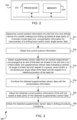
- Fig. 3 illustrates an example flow chart of a control method 300 for the mobile underground drilling rig 1, in accordance with an example embodiment.
- the method 300 comprises a computer-implemented method.
- control apparatus 200 may determine the current position information of the drill tool 7 of the rock drilling device 6 based at least partly on the kinematic model data of the drilling boom 3 and/or the boom angle sensor 3a-3c data.
- the current position information (which may have been determined previously at operation 301) of the drill tool 7 is obtained at the control apparatus 200.
- the supplementary sensor data from the inertial measurement unit 11 is obtained at the control apparatus 200.
- the inertial measurement unit 11 is arranged at the end of the feed rail 5 closest to the drill tool 7 or at the feed cradle 10, and the supplementary sensor data indicates the vertical tilt angle of the feed rail 5 with respect to the gravity vector and/or the horizontal yaw angle offset of the feed rail 5 with respect to the reference position of the feed rail 5.
- the kinematic model data of the drilling boom 3 may comprise the compensation information for inaccuracies.
- the control apparatus 200 may combine the obtained supplementary sensor data with the compensation information.
- control apparatus 200 adjusts the obtained current position information of the drill tool 7 based at least partly on the obtained supplementary sensor data.
- control apparatus 200 may utilize the obtained supplementary sensor data in monitoring the drilling procedure.
- the method 300 may be performed by the control apparatus 200 of Fig. 2 .
- the operations 301-306 can, for example, be performed by the at least one processor 202 and the at least one memory 204. Further features of the method 300 directly result from the functionalities and parameters of the control apparatus 200, and thus are not repeated here.
- the method 300 can be performed by computer program(s).
- the control apparatus 200 may comprise means for performing at least one method described herein.
- the means may comprise the at least one processor 202, and the at least one memory 204 including program code configured to, when executed by the at least one processor 202, cause the control apparatus 200 to perform the method.
- At least some of the disclosed example embodiments may allow enhancing drilling accuracy for a mobile underground drilling rig.
- a vertical orientation error caused by the drilling boom 3 and/or feed rail 5 bending may be directly measured and corrected, for example.
- a position error caused by the drilling boom 3 bending may be corrected or at least reduced by using the IMU 11 data in the compensation data/models.
- Such combined/new compensation data does not depend on drilling direction, such as face drilling, ramp drilling, and cross-cut drilling.
- the IMU 11 may be used to measure a change in a feed angle caused by contact forces between the feed rail 5 and rock, thereby further improving overall mining accuracy.
- the change in the feed angle may comprise a relative change, and at least in some embodiments, the relative change in the feed angle may be combined with calculated (and possibly compensated) position/angle data.
- control apparatus 200 may comprise a processor or processor circuitry, such as for example a microcontroller, configured by the program code when executed to execute the embodiments of the operations and functionality described.
- the functionality described herein can be performed, at least in part, by one or more hardware logic components.
- FPGAs Field-programmable Gate Arrays
- ASICs Application-specific Integrated Circuits
- ASSPs Application-specific Standard Products
- SOCs System-on-a-chip systems
- CPLDs Complex Programmable Logic Devices
- GPUs Graphics Processing Units
Landscapes
- Engineering & Computer Science (AREA)
- Mining & Mineral Resources (AREA)
- Life Sciences & Earth Sciences (AREA)
- Geology (AREA)
- General Life Sciences & Earth Sciences (AREA)
- Geochemistry & Mineralogy (AREA)
- Mechanical Engineering (AREA)
- Physics & Mathematics (AREA)
- Environmental & Geological Engineering (AREA)
- Fluid Mechanics (AREA)
- Earth Drilling (AREA)
Abstract
Description
- The present disclosure relates to the field of industrial systems, and, more particularly, to enhancing drilling accuracy for a mobile underground drilling rig, as well as related devices, methods and computer programs.
- Mobile underground drilling rig work in a challenging environment, such as in an underground mine.
- Rock drilling is typically carried out by using drilling equipment comprising a carrier provided with at least one boom with a rock drilling unit at a distal end of the at least one boom. The rock drilling unit comprises a feeding system configured to keep a drill bit in contact with rock during drilling. The feeding system comprises a feed rail configured to support and guide a rock drilling device that is configured to move along the feed rail during a drilling procedure. As accurate control of the feed rail enables accurate rock drilling, controlling the position of the feed rail plays a role in efficient operation.
- The scope of protection sought for various example embodiments of the disclosure is set out by the independent claims. The example embodiments and features, if any, described in this specification that do not fall under the scope of the independent claims are to be interpreted as examples useful for understanding various example embodiments of the disclosure.
- An example embodiment of a control apparatus for a mobile underground drilling rig comprises at least one processor, and at least one memory including computer program code. The mobile underground drilling rig comprises a drilling boom and a feed rail configured to move with respect to a feed cradle connected to the drilling boom. The feed rail is further configured to support and guide a rock drilling device arranged to move along the feed rail during a drilling procedure. The at least one memory and the computer program code are configured to, with the at least one processor, cause the control apparatus at least to obtain current position information of a drill tool of the rock drilling device. The at least one memory and the computer program code are further configured to, with the at least one processor, cause the control apparatus at least to obtain supplementary sensor data from an inertial measurement unit arranged at an end of the feed rail closest to the drill tool or at the feed cradle. The supplementary sensor data indicates at least one of a vertical tilt angle, v, of the feed rail with respect to a gravity vector or a horizontal yaw angle, u, offset of the feed rail with respect to a reference position of the feed rail. The at least one memory and the computer program code are further configured to, with the at least one processor, cause the control apparatus at least to adjust the obtained current position information of the drill tool based at least partly on the obtained supplementary sensor data.
- An example embodiment of a control method for a mobile underground drilling rig comprising a drilling boom and a feed rail configured to move with respect to a feed cradle connected to the drilling boom, the feed rail being further configured to support and guide a rock drilling device arranged to move along the feed rail during a drilling procedure, comprises obtaining, at a control apparatus for the mobile underground drilling rig, current position information of a drill tool of the rock drilling device. The control method further comprises obtaining, at the control apparatus, supplementary sensor data from an inertial measurement unit arranged at an end of the feed rail closest to the drill tool or at the feed cradle, the supplementary sensor data indicating at least one of a vertical tilt angle of the feed rail with respect to a gravity vector or a horizontal yaw angle offset of the feed rail with respect to a reference position of the feed rail. The control method further comprises adjusting, by the control apparatus, the obtained current position information of the drill tool based at least partly on the obtained supplementary sensor data.
- An example embodiment of a computer program comprises instructions for causing a control apparatus for a mobile underground drilling rig comprising a drilling boom and a feed rail configured to move with respect to a feed cradle connected to the drilling boom, the feed rail being further configured to support and guide a rock drilling device arranged to move along the feed rail during a drilling procedure, to perform at least the following: obtaining current position information of a drill tool of the rock drilling device; obtaining supplementary sensor data from an inertial measurement unit arranged at an end of the feed rail closest to the drill tool or at the feed cradle, the supplementary sensor data indicating at least one of a vertical tilt angle of the feed rail with respect to a gravity vector or a horizontal yaw angle offset of the feed rail with respect to a reference position of the feed rail; and adjusting the obtained current position information of the drill tool based at least partly on the obtained supplementary sensor data.
- In an example embodiment, alternatively or in addition to the above-described example embodiments, the at least one memory and the computer program code are further configured to, with the at least one processor, cause the control apparatus to determine the current position information of the drill tool based at least partly on at least one of kinematic model data of the drilling boom or boom angle sensor data.
- In an example embodiment, alternatively or in addition to the above-described example embodiments, the kinematic model data of the drilling boom comprises compensation information for inaccuracies.
- In an example embodiment, alternatively or in addition to the above-described example embodiments, the compensation information comprises at least one of first compensation data for a bending of at least one of the drilling boom or the feed rail, second compensation data for a position of the drill tool, or third compensation data for a roll angle of the drill tool.
- In an example embodiment, alternatively or in addition to the above-described example embodiments, the at least one memory and the computer program code are further configured to, with the at least one processor, cause the control apparatus to combine the obtained supplementary sensor data with the compensation information.
- In an example embodiment, alternatively or in addition to the above-described example embodiments, the at least one memory and the computer program code are further configured to, with the at least one processor, cause the control apparatus to utilize the obtained supplementary sensor data in monitoring the drilling procedure.
- An example embodiment of a mobile underground drilling rig comprises a drilling boom. The mobile underground drilling rig further comprises a feed rail configured to move with respect to a feed cradle connected to the drilling boom. The feed rail is further configured to support and guide a rock drilling device arranged to move along the feed rail during a drilling procedure. The mobile underground drilling rig further comprises an inertial measurement unit arranged at an end of the feed rail closest to a drill tool of the rock drilling device or at the feed cradle. The mobile underground drilling rig further comprises the control apparatus according to any of the above-described example embodiments.
- In an example embodiment, alternatively or in addition to the above-described example embodiments, the inertial measurement unit comprises at least one accelerometer and at least one gyroscope.
- In an example embodiment, alternatively or in addition to the above-described example embodiments, the at least one accelerometer comprises at least one accelerometer of at least one axis.
- In an example embodiment, alternatively or in addition to the above-described example embodiments, the at least one gyroscope comprises at least one gyroscope of at least one axis.
- Many of the features will be more readily appreciated as they become better understood by reference to the following detailed description considered in connection with the accompanying drawings.
- The accompanying drawings, which are included to provide a further understanding of the embodiments and constitute a part of this specification, illustrate embodiments and together with the description help to explain the principles of the embodiments. In the drawings:
-
FIG. 1 shows an example embodiment of the subject matter described herein illustrating an example mobile underground drilling rig, where various embodiments of the present disclosure may be implemented; -
FIG. 2 shows an example embodiment of the subject matter described herein illustrating an example control apparatus for a mobile mining vehicle, where various embodiments of the present disclosure may be implemented; -
FIG. 3 shows an example embodiment of the subject matter described herein illustrating a method; and -
FIG. 4 shows an example embodiment of the subject matter described herein illustrating a diagram showing a vertical tilt angle and a horizontal yaw angle. - Like reference numerals are used to designate like parts in the accompanying drawings.
- Reference will now be made in detail to embodiments, examples of which are illustrated in the accompanying drawings. The detailed description provided below in connection with the appended drawings is intended as a description of the present examples and is not intended to represent the only forms in which the present example may be constructed or utilized. The description sets forth the functions of the example and the sequence of steps for constructing and operating the example. However, the same or equivalent functions and sequences may be accomplished by different examples.
-
Fig. 1 illustrates an example mobile underground drilling rig 1, where various embodiments of the present disclosure may be implemented. - The mobile underground drilling rig 1 comprises a drilling boom 3. The mobile underground drilling rig 1 further comprises a
feed rail 5 configured to move with respect to afeed cradle 10 connected to the drilling boom 3. Thefeed rail 5 is further configured to support and guide a rock drilling device 6 arranged to move along thefeed rail 5 during a drilling procedure. - The mobile underground drilling rig 1 may further comprise a
carrier 2 and a drilling unit 4 associated with the drilling boom 3. The drilling boom 3 may comprise one or moreboom angle sensors feed rail 5 on which the rock drilling device 6 can be moved. Further, the drilling unit 4 may comprise a drill tool 7 with which impact pulses given by a percussion device of the rock drilling device 6 are transmitted to the rock to be drilled. - In the example of
Fig. 1 , the mobile underground drilling rig 1 may further comprise at least one control unit 8 arranged to control actuators of the mobile underground drilling rig 1, for example. The control unit 8 may comprise or be connected to a user interface with adisplay device 9 as well as operator input interface for receiving operator commands and information to the control unit 8. In some embodiments, the control unit 8 is configured to control at least boom automation control related operations, and there may be one or more other control units in the mobile underground drilling rig 1 for controlling other operations. - The mobile underground drilling rig 1 further comprises an inertial measurement unit (IMU) 11 that is arranged at an end of the
feed rail 5 closest to the drill tool 7 or at thefeed cradle 10. - At least in some embodiments, the IMU 11 may comprise at least one accelerometer and at least one gyroscope. For example, the at least one accelerometer may comprise at least one accelerometer of at least one axis. For example, the at least one gyroscope may comprise at least one gyroscope of at least one axis. At least in some embodiments, the at least one accelerometer may comprise a three-axis accelerometer, and/or the at least one gyroscope may comprise a three-axis gyroscope.
- The three-axis accelerometer may comprise three accelerometers mounted orthogonally, thereby enabling analyzing separate components of acceleration. The three-axis accelerometer may be configured to measure three mutually orthogonal components of acceleration of gravity. The three-axis gyroscope may comprise three orientation sensors, thereby configured to measure rotation around three axes such as pitch, yaw and roll.
- The mobile underground drilling rig 1 further comprises a
control apparatus 200. Thecontrol apparatus 200 will be described in more detail below in connection withFig. 2 . At least in some embodiments, thecontrol apparatus 200 may be comprised in the control unit 8. - In the following, various example embodiments will be discussed. At least some of these example embodiments may allow enhancing drilling accuracy for the mobile underground drilling rig 1. Some of the described features are optional features which may provide further advantages.
-
Fig. 2 is a block diagram of thecontrol apparatus 200 for the mobile underground drilling rig 1, in accordance with an example embodiment. Theapparatus 200 may be, for example, an electronic device such as a module comprised in an automation or control system, a chip or a chipset. - The
control apparatus 200 comprises at least oneprocessor 202, and at least onememory 204 including computer program code. Theapparatus 200 may also include other elements not shown inFig. 2 . Furthermore, at least in some embodiments, theapparatus 200 may be included or integrated in the control unit 8. - Although the
apparatus 200 is depicted to include only oneprocessor 202, theapparatus 200 may include more processors. In an embodiment, thememory 204 is capable of storing instructions, such as an operating system and/or various applications. Furthermore, thememory 204 may include a storage that may be used to store, for example, at least some of the information and data used in the disclosed embodiments. - Furthermore, the
processor 202 is capable of executing the stored instructions. In an embodiment, theprocessor 202 may be embodied as a multi-core processor, a single core processor, or a combination of one or more multi-core processors and one or more single core processors. For example, theprocessor 202 may be embodied as one or more of various processing devices, such as a coprocessor, a microprocessor, a controller, a digital signal processor (DSP), a processing circuitry with or without an accompanying DSP, or various other processing devices including integrated circuits such as, for example, an application specific integrated circuit (ASIC), a field programmable gate array (FPGA), a microcontroller unit (MCU), a hardware accelerator, a special-purpose computer chip, a neural network chip, an artificial intelligence (AI) accelerator, or the like. In an embodiment, theprocessor 202 may be configured to execute hard-coded functionality. In an embodiment, theprocessor 202 is embodied as an executor of software instructions, wherein the instructions may specifically configure theprocessor 202 to perform the algorithms and/or operations described herein when the instructions are executed. - The
memory 204 may be embodied as one or more volatile memory devices, one or more non-volatile memory devices, and/or a combination of one or more volatile memory devices and non-volatile memory devices. For example, thememory 204 may be embodied as semiconductor memories (such as mask ROM, PROM (programmable ROM), EPROM (erasable PROM), flash ROM, RAM (random access memory), etc.). - The at least one
memory 204 and the computer program code are configured to, with the at least oneprocessor 202, cause thecontrol apparatus 200 at least to obtain current position information of the drill tool 7 of the rock drilling device 6. - At least in some embodiments, the at least one
memory 204 and the computer program code may further be configured to, with the at least oneprocessor 202, cause thecontrol apparatus 200 to determine the current position information of the drill tool 7 based at least partly on kinematic model data of the drilling boom 3 and/or data from the boom angle sensor(s) 3a-3c. - For example, the kinematic model data may comprise information on physical characteristics of mobile underground drilling rig 1 or components thereof. According to an example embodiment, the kinematic model data may comprise information on physical characteristics of mobile underground drilling rig 1 or components thereof affecting positioning of drill tool 7. For example, the kinematic model data may comprise dimensions and/or reach of mobile underground drilling rig 1 or component (s) thereof, such as dimensions of drilling boom 3 and/or mobile underground drilling rig 1, reach of drilling boom 3, characteristics of the joints (e.g., type of the joints, such as rotational or prismatic), constraints between the moving parts of mobile underground drilling rig 1, or the like.
- At least in some embodiments, a kinematic model of the mobile underground drilling rig 1, or component(s) thereof, may comprise a mathematical description of at least a part of the mobile underground drilling rig 1. The kinematic model may describe a motion of the mobile underground drilling rig 1 or a motion of component(s) of the mobile underground drilling 1 without taking into account the forces that cause the motion. Accordingly, the kinematic model may be used, e.g., to determine a position of a component of the mobile underground drilling rig 1 based on sensor data, such as the data from the boom angle sensor(s) 3a-3c.
- At least in some embodiments, the kinematic model data of the drilling boom 3 may comprise compensation information for inaccuracies caused by, e.g., mechanical bending and/or manufacturing tolerances (e.g., inaccuracies in the position information of the drill tool 7) . In other words, the compensation information may be used to model the inaccuracies caused by the mechanical bending, the manufacturing tolerances, and/or the like. For example, the compensation information may comprise first compensation data for a bending of the drilling boom 3 and/or the
feed rail 5, second compensation data for a position (herein, "position" may include "orientation") of the drill tool 7, and/or third compensation data for a roll angle of the drill tool 7. - Here, "bending" compensation relates to compensation of longitudinal motions of the drilling boom 3 and/or the
feed rail 5, "position" compensation relates to compensation of sideward/horizontal/vertical motions of the drilling boom 3 and/or thefeed rail 5, and "roll angle or roll-over" compensation relates to compensation of rotating motions of the drilling boom 3 around a drill rod of the rock drilling device 6. Such a bending compensation may be modelled, e.g., with a bending compensation model of drilling boom 3 and/or feedrail 5. - The at least one
memory 204 and the computer program code are further configured to, with the at least oneprocessor 202, cause thecontrol apparatus 200 at least to obtain supplementary sensor data from theIMU 11 arranged at the end of thefeed rail 5 closest to the drill tool 7 or at thefeed cradle 10. Herein, the "supplementary" in the supplementary sensor data indicates that the supplementary sensor data is for supplementing the obtained current position information of the drill tool 7 of the rock drilling device 6, as described in more detail below. The supplementary sensor data indicates a vertical tilt angle (illustrated as "v" in diagram 400 ofFig. 4 ) of thefeed rail 5 with respect to a gravity vector and/or a horizontal yaw angle (illustrated as "u" in diagram 400 ofFig. 4 ) offset of thefeed rail 5 with respect to a reference position of thefeed rail 5. - At least in some embodiments, the at least one
memory 204 and the computer program code may further be configured to, with the at least oneprocessor 202, cause thecontrol apparatus 200 to combine the obtained supplementary sensor data with the compensation information. - For example, a pre-generated boom bending compensation model may be enhanced by the disclosed supplementary sensor data. At least in some situations, external forces may cause the data in the pre-generated boom bending compensation model (e.g., related to the positioning of drill tool 7) to be erroneous. The disclosed supplementary sensor data may be used to correct and/or detect such errors.
- Alternatively, the disclosed supplementary sensor data may be used to enhance or correct data in a rigid kinematic model of the joints and other components of mobile underground drilling rig 1.
- The at least one
memory 204 and the computer program code are further configured to, with the at least oneprocessor 202, cause thecontrol apparatus 200 at least to adjust the obtained current position information of the drill tool 7 based at least partly on the obtained supplementary sensor data. - For example, the kinematic model data may comprise data on distances between joints of the drilling boom 3, and/or data on angles of the joints of the drilling boom 3. In other words, the kinematic model data may comprise data on dimensions of the drilling boom 3. Accordingly, the kinematic model data may further be used, e.g., in determining/obtaining initial measurements for the position of the drill tool 7. Accuracy of the thus determined/obtained initial measurements may then be improved with the compensation information that may compensate for various possible inaccuracies in the initial measurements. After that, the disclosed supplementary sensor data from the
IMU 11 may be used to adjust the initial measurements (e.g., directly or by enhancing/correcting data in the rigid kinematic model, as discussed above), thereby further enhancing drilling accuracy for the mobile underground drilling rig 1. Furthermore, data from theIMU 11 may be used as input for the compensation information. - At least in some embodiments, the at least one
memory 204 and the computer program code may further be configured to, with the at least oneprocessor 202, cause thecontrol apparatus 200 to utilize the obtained supplementary sensor data in monitoring the drilling procedure. For example, the monitoring may comprise monitoring whether thefeed rail 5 loses contact with the rock while drilling. -
Fig. 3 illustrates an example flow chart of acontrol method 300 for the mobile underground drilling rig 1, in accordance with an example embodiment. In the example ofFig. 3 , themethod 300 comprises a computer-implemented method. - At
optional operation 301, thecontrol apparatus 200 may determine the current position information of the drill tool 7 of the rock drilling device 6 based at least partly on the kinematic model data of the drilling boom 3 and/or theboom angle sensor 3a-3c data. - At
operation 302, the current position information (which may have been determined previously at operation 301) of the drill tool 7 is obtained at thecontrol apparatus 200. - At
operation 303, the supplementary sensor data from theinertial measurement unit 11 is obtained at thecontrol apparatus 200. As described above, theinertial measurement unit 11 is arranged at the end of thefeed rail 5 closest to the drill tool 7 or at thefeed cradle 10, and the supplementary sensor data indicates the vertical tilt angle of thefeed rail 5 with respect to the gravity vector and/or the horizontal yaw angle offset of thefeed rail 5 with respect to the reference position of thefeed rail 5. - As described above, the kinematic model data of the drilling boom 3 may comprise the compensation information for inaccuracies. At
optional operation 304, thecontrol apparatus 200 may combine the obtained supplementary sensor data with the compensation information. - At
operation 305, thecontrol apparatus 200 adjusts the obtained current position information of the drill tool 7 based at least partly on the obtained supplementary sensor data. - At
optional operation 306, thecontrol apparatus 200 may utilize the obtained supplementary sensor data in monitoring the drilling procedure. - The
method 300 may be performed by thecontrol apparatus 200 ofFig. 2 . The operations 301-306 can, for example, be performed by the at least oneprocessor 202 and the at least onememory 204. Further features of themethod 300 directly result from the functionalities and parameters of thecontrol apparatus 200, and thus are not repeated here. Themethod 300 can be performed by computer program(s). - The
control apparatus 200 may comprise means for performing at least one method described herein. In an example, the means may comprise the at least oneprocessor 202, and the at least onememory 204 including program code configured to, when executed by the at least oneprocessor 202, cause thecontrol apparatus 200 to perform the method. - At least some of the disclosed example embodiments may allow enhancing drilling accuracy for a mobile underground drilling rig. With the disclosed
IMU 11, a vertical orientation error caused by the drilling boom 3 and/or feedrail 5 bending may be directly measured and corrected, for example. A position error caused by the drilling boom 3 bending may be corrected or at least reduced by using theIMU 11 data in the compensation data/models. Such combined/new compensation data does not depend on drilling direction, such as face drilling, ramp drilling, and cross-cut drilling. Furthermore, theIMU 11 may be used to measure a change in a feed angle caused by contact forces between thefeed rail 5 and rock, thereby further improving overall mining accuracy. The change in the feed angle may comprise a relative change, and at least in some embodiments, the relative change in the feed angle may be combined with calculated (and possibly compensated) position/angle data. - The functionality described herein can be performed, at least in part, by one or more computer program product components such as software components. According to an embodiment, the
control apparatus 200 may comprise a processor or processor circuitry, such as for example a microcontroller, configured by the program code when executed to execute the embodiments of the operations and functionality described. Alternatively, or in addition, the functionality described herein can be performed, at least in part, by one or more hardware logic components. For example, and without limitation, illustrative types of hardware logic components that can be used include Field-programmable Gate Arrays (FPGAs), Application-specific Integrated Circuits (ASICs), Application-specific Standard Products (ASSPs), System-on-a-chip systems (SOCs), Complex Programmable Logic Devices (CPLDs), and Graphics Processing Units (GPUs). - Any range or device value given herein may be extended or altered without losing the effect sought. Further, any embodiment may be combined with another embodiment unless explicitly disallowed.
- Although the subject matter has been described in language specific to structural features and/or acts, it is to be understood that the subject matter defined in the appended claims is not necessarily limited to the specific features or acts described above. Rather, the specific features and acts described above are disclosed as examples of implementing the claims and other equivalent features and acts are intended to be within the scope of the claims.
- It will be understood that the benefits and advantages described above may relate to one embodiment or may relate to several embodiments. The embodiments are not limited to those that solve any or all of the stated problems or those that have any or all of the stated benefits and advantages. It will further be understood that reference to 'an' item may refer to one or more of those items.
- The steps of the methods described herein may be carried out in any suitable order, or simultaneously where appropriate. Additionally, individual blocks may be deleted from any of the methods without departing from the spirit and scope of the subject matter described herein. Aspects of any of the embodiments described above may be combined with aspects of any of the other embodiments described to form further embodiments without losing the effect sought.
- The term 'comprising' is used herein to mean including the method, blocks or elements identified, but that such blocks or elements do not comprise an exclusive list and a method or apparatus may contain additional blocks or elements.
- It will be understood that the above description is given by way of example only and that various modifications may be made by those skilled in the art. The above specification, examples and data provide a complete description of the structure and use of example embodiments. Although various embodiments have been described above with a certain degree of particularity, or with reference to one or more individual embodiments, those skilled in the art could make numerous alterations to the disclosed embodiments without departing from the scope of this specification.
Claims (12)
- A control apparatus (200) for a mobile underground drilling rig (1) comprising a drilling boom (3) and a feed rail (5) configured to move with respect to a feed cradle (10) connected to the drilling boom (3), the feed rail (5) being further configured to support and guide a rock drilling device (6) arranged to move along the feed rail (5) during a drilling procedure, the control apparatus (200) comprising:at least one processor (202); andat least one memory (204) including computer program code;the at least one memory (204) and the computer program code configured to, with the at least one processor (202), cause the control apparatus (200) at least to:obtain current position information of a drill tool (7) of the rock drilling device (6);obtain supplementary sensor data from an inertial measurement unit (11) arranged at an end of the feed rail (5) closest to the drill tool (7) or at the feed cradle (10), the supplementary sensor data indicating at least one of a vertical tilt angle, v, of the feed rail (5) with respect to a gravity vector or a horizontal yaw angle, u, offset of the feed rail (5) with respect to a reference position of the feed rail (5); andadjust the obtained current position information of the drill tool (7) based at least partly on the obtained supplementary sensor data.
- The control apparatus (200) according to claim 1, wherein the at least one memory (204) and the computer program code are further configured to, with the at least one processor (202), cause the control apparatus (200) to determine the current position information of the drill tool (7) based at least partly on at least one of kinematic model data of the drilling boom (3) or boom angle sensor (3a-3c) data.
- The control apparatus (200) according to claim 2, wherein the kinematic model data of the drilling boom (3) comprises compensation information for inaccuracies.
- The control apparatus (200) according to claim 3, wherein the compensation information comprises at least one of first compensation data for a bending of at least one of the drilling boom (3) or the feed rail (5), second compensation data for a position of the drill tool (7), or third compensation data for a roll angle of the drill tool (7).
- The control apparatus (200) according to claim 3 or 4, wherein the at least one memory (204) and the computer program code are further configured to, with the at least one processor (202), cause the control apparatus (200) to combine the obtained supplementary sensor data with the compensation information.
- The control apparatus (200) according to any of claims 1 to 5, wherein the at least one memory (204) and the computer program code are further configured to, with the at least one processor (202), cause the control apparatus (200) to utilize the obtained supplementary sensor data in monitoring the drilling procedure.
- A control method (300) for a mobile underground drilling rig (1) comprising a drilling boom (3) and a feed rail (5) configured to move with respect to a feed cradle (10) connected to the drilling boom (3), the feed rail (5) being further configured to support and guide a rock drilling device (6) arranged to move along the feed rail (5) during a drilling procedure, the control method () comprising:obtaining (302), at a control apparatus (200) for the mobile underground drilling rig (1), current position information of a drill tool (7) of the rock drilling device (6);obtaining (303), at the control apparatus (200), supplementary sensor data from an inertial measurement unit (11) arranged at an end of the feed rail (5) closest to the drill tool (7) or at the feed cradle (10), the supplementary sensor data indicating at least one of a vertical tilt angle of the feed rail (5) with respect to a gravity vector or a horizontal yaw angle offset of the feed rail (5) with respect to a reference position of the feed rail (5); andadjusting (305), by the control apparatus (200), the obtained current position information of the drill tool (7) based at least partly on the obtained supplementary sensor data.
- A computer program comprising instructions for causing a control apparatus for a mobile underground drilling rig comprising a drilling boom and a feed rail configured to move with respect to a feed cradle connected to the drilling boom, the feed rail being further configured to support and guide a rock drilling device arranged to move along the feed rail during a drilling procedure, to perform at least the following:obtaining current position information of a drill tool of the rock drilling device;obtaining supplementary sensor data from an inertial measurement unit arranged at an end of the feed rail closest to the drill tool or at the feed cradle, the supplementary sensor data indicating at least one of a vertical tilt angle of the feed rail with respect to a gravity vector or a horizontal yaw angle offset of the feed rail with respect to a reference position of the feed rail; andadjusting the obtained current position information of the drill tool based at least partly on the obtained supplementary sensor data.
- A mobile underground drilling rig (1), comprising:a drilling boom (3);a feed rail (5) configured to move with respect to a feed cradle (10) connected to the drilling boom (3), the feed rail (5) being further configured to support and guide a rock drilling device (6) arranged to move along the feed rail (5) during a drilling procedure;an inertial measurement unit (11) arranged at an end of the feed rail (5) closest to a drill tool (7) of the rock drilling device (6) or at the feed cradle (10); andthe control apparatus (200) according to any of claims 1 to 6.
- The mobile underground drilling rig (1) according to claim 9, wherein the inertial measurement unit (11) comprises at least one accelerometer and at least one gyroscope.
- The mobile underground drilling rig (1) according to claim 10, wherein the at least one accelerometer comprises at least one accelerometer of at least one axis.
- The mobile underground rig (1) according to claim 10 or 11, wherein the at least one gyroscope comprises at least one gyroscope of at least one axis.
Priority Applications (6)
| Application Number | Priority Date | Filing Date | Title |
|---|---|---|---|
| EP23206959.1A EP4549694B1 (en) | 2023-10-31 | 2023-10-31 | Enhancing drilling accuracy for a mobile underground drilling rig, and related devices, methods and computer programs |
| PCT/EP2024/080899 WO2025093716A1 (en) | 2023-10-31 | 2024-10-31 | Enhancing drilling accuracy for a mobile underground drilling rig, and related devices, methods and computer programs |
| AU2024370763A AU2024370763A1 (en) | 2023-10-31 | 2024-10-31 | Enhancing drilling accuracy for a mobile underground drilling rig, and related devices, methods and computer programs |
| CN202480060706.9A CN121889564A (en) | 2023-10-31 | 2024-10-31 | Improving drilling accuracy of a mobile subterranean drilling rig and related apparatus, methods and computer programs |
| CL2026000556A CL2026000556A1 (en) | 2023-10-31 | 2026-02-25 | Improvement of drilling accuracy for a mobile underground drilling rig, and related devices, methods and computer programs. |
| MX2026005152A MX2026005152A (en) | 2023-10-31 | 2026-04-28 | Enhancing drilling accuracy for a mobile underground drilling rig, and related devices, methods and computer programs |
Applications Claiming Priority (1)
| Application Number | Priority Date | Filing Date | Title |
|---|---|---|---|
| EP23206959.1A EP4549694B1 (en) | 2023-10-31 | 2023-10-31 | Enhancing drilling accuracy for a mobile underground drilling rig, and related devices, methods and computer programs |
Publications (3)
| Publication Number | Publication Date |
|---|---|
| EP4549694A1 true EP4549694A1 (en) | 2025-05-07 |
| EP4549694B1 EP4549694B1 (en) | 2026-03-25 |
| EP4549694C0 EP4549694C0 (en) | 2026-03-25 |
Family
ID=88757475
Family Applications (1)
| Application Number | Title | Priority Date | Filing Date |
|---|---|---|---|
| EP23206959.1A Active EP4549694B1 (en) | 2023-10-31 | 2023-10-31 | Enhancing drilling accuracy for a mobile underground drilling rig, and related devices, methods and computer programs |
Country Status (6)
| Country | Link |
|---|---|
| EP (1) | EP4549694B1 (en) |
| CN (1) | CN121889564A (en) |
| AU (1) | AU2024370763A1 (en) |
| CL (1) | CL2026000556A1 (en) |
| MX (1) | MX2026005152A (en) |
| WO (1) | WO2025093716A1 (en) |
Citations (2)
| Publication number | Priority date | Publication date | Assignee | Title |
|---|---|---|---|---|
| WO2022250674A1 (en) * | 2021-05-27 | 2022-12-01 | Vector Magnetics Llc | A downhole assembly with spring isolation filter |
| EP4148231A1 (en) * | 2021-09-08 | 2023-03-15 | Sandvik Mining and Construction Oy | Providing control information |
Family Cites Families (1)
| Publication number | Priority date | Publication date | Assignee | Title |
|---|---|---|---|---|
| EP2725184B1 (en) * | 2012-10-24 | 2019-05-15 | Sandvik Mining and Construction Oy | Rock drilling apparatus and method for controlling the orientation of the feed beam |
-
2023
- 2023-10-31 EP EP23206959.1A patent/EP4549694B1/en active Active
-
2024
- 2024-10-31 CN CN202480060706.9A patent/CN121889564A/en active Pending
- 2024-10-31 AU AU2024370763A patent/AU2024370763A1/en active Pending
- 2024-10-31 WO PCT/EP2024/080899 patent/WO2025093716A1/en active Pending
-
2026
- 2026-02-25 CL CL2026000556A patent/CL2026000556A1/en unknown
- 2026-04-28 MX MX2026005152A patent/MX2026005152A/en unknown
Patent Citations (2)
| Publication number | Priority date | Publication date | Assignee | Title |
|---|---|---|---|---|
| WO2022250674A1 (en) * | 2021-05-27 | 2022-12-01 | Vector Magnetics Llc | A downhole assembly with spring isolation filter |
| EP4148231A1 (en) * | 2021-09-08 | 2023-03-15 | Sandvik Mining and Construction Oy | Providing control information |
Also Published As
| Publication number | Publication date |
|---|---|
| CL2026000556A1 (en) | 2026-06-26 |
| EP4549694B1 (en) | 2026-03-25 |
| WO2025093716A1 (en) | 2025-05-08 |
| MX2026005152A (en) | 2026-06-01 |
| AU2024370763A1 (en) | 2026-03-12 |
| EP4549694C0 (en) | 2026-03-25 |
| CN121889564A (en) | 2026-04-17 |
Similar Documents
| Publication | Publication Date | Title |
|---|---|---|
| JP4860697B2 (en) | Acceleration sensor correction apparatus and acceleration sensor output value correction method | |
| AU2008240564A1 (en) | Method of directing drilling pattern in curved tunnels, rock drilling rig, and software product | |
| US20180202129A1 (en) | Work machine control system, work machine, and work machine control method | |
| CN109540130A (en) | A kind of continuous milling machine inertial navigation positioning and orienting method | |
| CN112013869A (en) | Moving body, sensor module, and calibration method for sensor module | |
| AU2008201684A1 (en) | Heading stabilization for aided inertial navigation systems | |
| CN116026322B (en) | A shield tunneling posture measurement method and system | |
| CN109866217B (en) | Robot mileage positioning method, device, terminal equipment and computer storage medium | |
| US12578194B2 (en) | Positioning and orientation method, apparatus, and device | |
| CN119620095A (en) | A laser ranging method and device based on attitude sensor | |
| CN113048972B (en) | Method and system for determining attitude and position of mining engineering machinery | |
| EP4549694B1 (en) | Enhancing drilling accuracy for a mobile underground drilling rig, and related devices, methods and computer programs | |
| EP4148231A1 (en) | Providing control information | |
| CN114705221B (en) | Calibration method, device, equipment and readable storage medium of inertial measurement unit | |
| CN112557072B (en) | Calibration method and device for cantilever space degree of freedom of mining equipment | |
| JP6273783B2 (en) | Tool tip information correction program, tool tip information correction apparatus, and tool tip information correction method | |
| CN120269561A (en) | Equipment relative positioning method and device and electronic equipment | |
| EP3757299B1 (en) | Apparatus for generating environment data around construction equipment and construction equipment including the same | |
| CN115771144B (en) | A parameter configuration method, device, equipment and medium for an industrial robot | |
| US11893167B2 (en) | Information processing device, information processing method, non-transitory computer readable medium | |
| CN117723054A (en) | Positioning method of integrated anchor digger based on strapdown inertial navigation and binocular visual displacement information fusion | |
| EP4571040B1 (en) | Controlling of a mining machine | |
| CN119871398B (en) | Secondary calibration method, system and equipment for rock drilling boom and storage medium | |
| CN116852377B (en) | Method, device and computer equipment for determining jitter data of robot joints | |
| CN117606768B (en) | Spatially-diverse axial calibration method suitable for rotary machine |
Legal Events
| Date | Code | Title | Description |
|---|---|---|---|
| PUAI | Public reference made under article 153(3) epc to a published international application that has entered the european phase |
Free format text: ORIGINAL CODE: 0009012 |
|
| STAA | Information on the status of an ep patent application or granted ep patent |
Free format text: STATUS: THE APPLICATION HAS BEEN PUBLISHED |
|
| AK | Designated contracting states |
Kind code of ref document: A1 Designated state(s): AL AT BE BG CH CY CZ DE DK EE ES FI FR GB GR HR HU IE IS IT LI LT LU LV MC ME MK MT NL NO PL PT RO RS SE SI SK SM TR |
|
| STAA | Information on the status of an ep patent application or granted ep patent |
Free format text: STATUS: REQUEST FOR EXAMINATION WAS MADE |
|
| 17P | Request for examination filed |
Effective date: 20251107 |
|
| GRAP | Despatch of communication of intention to grant a patent |
Free format text: ORIGINAL CODE: EPIDOSNIGR1 |
|
| STAA | Information on the status of an ep patent application or granted ep patent |
Free format text: STATUS: GRANT OF PATENT IS INTENDED |
|
| GRAS | Grant fee paid |
Free format text: ORIGINAL CODE: EPIDOSNIGR3 |
|
| INTG | Intention to grant announced |
Effective date: 20260120 |
|
| GRAA | (expected) grant |
Free format text: ORIGINAL CODE: 0009210 |
|
| STAA | Information on the status of an ep patent application or granted ep patent |
Free format text: STATUS: THE PATENT HAS BEEN GRANTED |
|
| AK | Designated contracting states |
Kind code of ref document: B1 Designated state(s): AL AT BE BG CH CY CZ DE DK EE ES FI FR GB GR HR HU IE IS IT LI LT LU LV MC ME MK MT NL NO PL PT RO RS SE SI SK SM TR |
|
| REG | Reference to a national code |
Ref country code: CH Ref legal event code: F10 Free format text: ST27 STATUS EVENT CODE: U-0-0-F10-F00 (AS PROVIDED BY THE NATIONAL OFFICE) Effective date: 20260325 Ref country code: GB Ref legal event code: FG4D |
|
| REG | Reference to a national code |
Ref country code: IE Ref legal event code: FG4D |
|
| U01 | Request for unitary effect filed |
Effective date: 20260325 |
|
| U07 | Unitary effect registered |
Designated state(s): AT BE BG DE DK EE FI FR IT LT LU LV MT NL PT RO SE SI Effective date: 20260331 |
|
| PG25 | Lapsed in a contracting state [announced via postgrant information from national office to epo] |
Ref country code: RS Free format text: LAPSE BECAUSE OF FAILURE TO SUBMIT A TRANSLATION OF THE DESCRIPTION OR TO PAY THE FEE WITHIN THE PRESCRIBED TIME-LIMIT Effective date: 20260625 |
|
| PG25 | Lapsed in a contracting state [announced via postgrant information from national office to epo] |
Ref country code: GR Free format text: LAPSE BECAUSE OF FAILURE TO SUBMIT A TRANSLATION OF THE DESCRIPTION OR TO PAY THE FEE WITHIN THE PRESCRIBED TIME-LIMIT Effective date: 20260626 |
|
| PG25 | Lapsed in a contracting state [announced via postgrant information from national office to epo] |
Ref country code: HR Free format text: LAPSE BECAUSE OF FAILURE TO SUBMIT A TRANSLATION OF THE DESCRIPTION OR TO PAY THE FEE WITHIN THE PRESCRIBED TIME-LIMIT Effective date: 20260325 |