EP4549647A2 - Laundry treating apparatus - Google Patents
Laundry treating apparatus Download PDFInfo
- Publication number
- EP4549647A2 EP4549647A2 EP25159051.9A EP25159051A EP4549647A2 EP 4549647 A2 EP4549647 A2 EP 4549647A2 EP 25159051 A EP25159051 A EP 25159051A EP 4549647 A2 EP4549647 A2 EP 4549647A2
- Authority
- EP
- European Patent Office
- Prior art keywords
- housing
- output shaft
- drum
- treating apparatus
- cover
- Prior art date
- Legal status (The legal status is an assumption and is not a legal conclusion. Google has not performed a legal analysis and makes no representation as to the accuracy of the status listed.)
- Pending
Links
Images





Classifications
-
- D—TEXTILES; PAPER
- D06—TREATMENT OF TEXTILES OR THE LIKE; LAUNDERING; FLEXIBLE MATERIALS NOT OTHERWISE PROVIDED FOR
- D06F—LAUNDERING, DRYING, IRONING, PRESSING OR FOLDING TEXTILE ARTICLES
- D06F37/00—Details specific to washing machines covered by groups D06F21/00 - D06F25/00
- D06F37/30—Driving arrangements
-
- D—TEXTILES; PAPER
- D06—TREATMENT OF TEXTILES OR THE LIKE; LAUNDERING; FLEXIBLE MATERIALS NOT OTHERWISE PROVIDED FOR
- D06F—LAUNDERING, DRYING, IRONING, PRESSING OR FOLDING TEXTILE ARTICLES
- D06F58/00—Domestic laundry dryers
- D06F58/02—Domestic laundry dryers having dryer drums rotating about a horizontal axis
- D06F58/04—Details
- D06F58/08—Driving arrangements
-
- D—TEXTILES; PAPER
- D06—TREATMENT OF TEXTILES OR THE LIKE; LAUNDERING; FLEXIBLE MATERIALS NOT OTHERWISE PROVIDED FOR
- D06F—LAUNDERING, DRYING, IRONING, PRESSING OR FOLDING TEXTILE ARTICLES
- D06F37/00—Details specific to washing machines covered by groups D06F21/00 - D06F25/00
- D06F37/20—Mountings, e.g. resilient mountings, for the rotary receptacle, motor, tub or casing; Preventing or damping vibrations
- D06F37/206—Mounting of motor
-
- D—TEXTILES; PAPER
- D06—TREATMENT OF TEXTILES OR THE LIKE; LAUNDERING; FLEXIBLE MATERIALS NOT OTHERWISE PROVIDED FOR
- D06F—LAUNDERING, DRYING, IRONING, PRESSING OR FOLDING TEXTILE ARTICLES
- D06F37/00—Details specific to washing machines covered by groups D06F21/00 - D06F25/00
- D06F37/26—Casings; Tubs
- D06F37/261—Tubs made by a specially selected manufacturing process or characterised by their assembly from elements
-
- D—TEXTILES; PAPER
- D06—TREATMENT OF TEXTILES OR THE LIKE; LAUNDERING; FLEXIBLE MATERIALS NOT OTHERWISE PROVIDED FOR
- D06F—LAUNDERING, DRYING, IRONING, PRESSING OR FOLDING TEXTILE ARTICLES
- D06F37/00—Details specific to washing machines covered by groups D06F21/00 - D06F25/00
- D06F37/30—Driving arrangements
- D06F37/304—Arrangements or adaptations of electric motors
Definitions
- the present disclosure relates to a laundry treating apparatus.
- Washing treating apparatus is a general term for a washing machine for washing laundry (an object to be washed or an object to be dried), a dryer for drying laundry, and an apparatus capable of both washing and drying laundry.
- the washing machine generally includes a tub, which stores water therein, a washing drum, which is provided in the tub to store laundry therein, and a driving unit (a washing driving unit), which rotates the washing drum.
- the dryer generally includes a drying drum, which stores laundry therein, a driving unit (a drying driving unit), which rotates the drying drum, and a heat exchange unit, which supplies air to the drying drum to remove moisture from laundry.
- the washing driving unit generally includes a stator, which is secured to the tub to form a rotating magnetic field, a rotor, which is rotated by the rotating magnetic field, and a rotation shaft, which passes through the tub to connect the washing drum to the rotor.
- the drying driving unit generally includes a motor, a pulley, which is secured to the rotation shaft of the motor, and a belt (a power transmission unit), which transmits the rotational motion of the pulley to the drying drum.
- the washing driving unit is configured such that the rotation shaft of the motor connects the washing drum to the rotor.
- the washing driving unit needs to increase the rate of rotation of the washing drum or to change the rotation direction of the washing drum.
- the rotation shaft of the motor directly connects the washing drum to the rotor, it is possible to easily control the rate of rotation and the rotation direction of the washing drum.
- the conventional drying driving unit is generally structured such that a power transmission unit, such as a belt, connects the drying drum to the rotation shaft of the motor.
- a power transmission unit such as a belt
- the reason why the dryer employs a power transmission unit, such as a belt, in order to rotate the drying drum is that the rate of rotation of the drying drum does not need to be maintained particularly high and that the rotation direction of the drying drum generally does not need to be changed.
- the dryer is designed so as to be capable of changing the rate of rotation and the rotation direction of the drying drum, movement of laundry in the drying drum may be capable of being controlled, leading to a reduction in the drying time and improvement of drying performance.
- a conventional dryer that includes a drying driving unit connecting a rotor to a drying drum using a speed reducer
- the drying driving unit is structured such that an input shaft, connected to the rotor, and an output shaft, connected to the drying drum, are disposed coaxially. Accordingly, it may be possible to shorten the drying time or to improve drying performance.
- heat supplied to the drying drum is transferred to the inside of the drying driving unit, which may lead to deterioration in the durability of the drying driving unit.
- An object of the present disclosure is to provide a laundry treating apparatus, which includes a power transmission unit configured to connect an input shaft, which is connected to a rotor, and an output shaft, which is connected to a drum, to each other such that the input shaft and the output shaft are disposed coaxially.
- Another object of the present disclosure is to provide a laundry treating apparatus, which is capable of minimizing the transfer of external heat to the inside of the power transmission unit, thereby minimizing deterioration in the durability of the power transmission unit.
- Another object of the present disclosure is to provide a laundry treating apparatus, which includes a means for dissipating heat in the power transmission unit to the outside, thereby minimizing deterioration in the durability of the power transmission unit.
- Another object of the present disclosure is to provide a laundry treating apparatus, which is capable of minimizing deterioration in the durability of bearings supporting the input shaft and the output shaft caused by external force acting on the input shaft and the output shaft during operation of the power transmission unit.
- the present disclosure provides a laundry treating apparatus including a drum in which an object to be dried is accommodated, a drying unit configured to supply heated air to the drum, a fixing panel disposed at a position spaced apart from one surface of the drum, a power transmission unit, which includes a housing secured to the fixing panel, an input shaft having one end located outside the housing and an opposite end located in the housing, an output shaft having one end secured to the one surface of the drum and an opposite end located in the housing, and a gear unit located in the housing to transmit the rotational motion of the input shaft to the output shaft, a motor, which includes a stator secured to the housing to form a rotating magnetic field and a rotor configured to be rotated by the rotating magnetic field and to allow the one end of the input shaft to be secured thereto, and a heat insulation part made of a material having heat conductivity lower than the heat conductivity of the housing to reduce the amount of heat that is transferred from the outside of the housing to the inside thereof.
- a laundry treating apparatus including a drum, which includes a drum body providing a space to store laundry therein, a front cover forming the front surface of the drum body, a rear cover forming the rear surface of the drum body, and a drum introduction opening formed through the front cover to communicate with the inside of the drum body, a drying unit configured to supply heated air to the drum body, a fixing panel disposed at a position spaced apart from the rear cover, a power transmission unit, which includes a housing secured to the fixing panel, an input shaft having one end located outside the housing and an opposite end located in the housing, an output shaft having one end secured to the rear cover and an opposite end located in the housing, and a gear unit located in the housing to transmit the rotational motion of the input shaft to the output shaft, a motor, which includes a stator secured to the fixing panel or the housing to form a rotating magnetic field and a rotor configured to be rotated by the rotating magnetic field and to allow the one end of the input shaft to be secured thereto, and a heat
- the heat insulation part may be located on the surface of the housing that faces the fixing panel.
- the housing may be secured to the fixing panel so as to be located in a space isolated from the space in which the drum is located.
- the heat insulation part may be made of a material having heat conductivity lower than the heat conductivity of the fixing panel.
- the housing may include a housing body, which is formed in a hollow cylindrical shape and has an opening formed in the surface thereof that faces the fixing panel, and a housing cover, which is secured to the housing body to close the opening.
- the heat insulation part may be provided at the housing cover.
- the housing body and the housing cover may be made of a metallic material, and the heat insulation part may be made of a non-metallic material.
- the housing cover may include a cover body surrounding the opening, an output shaft through-hole formed through the cover body to allow the output shaft to be inserted thereinto, and an output shaft support portion protruding from the cover body toward the fixing panel and surrounding the output shaft through-hole.
- the heat insulation part may include a cover insulation body secured to the cover body and a support portion insulation body surrounding the circumferential surface of the output shaft support portion.
- the housing cover may further include a bent portion formed such that the region of the cover body in which the output shaft through-hole is formed protrudes toward the fixing panel.
- the housing cover and the cover insulation body may be formed integrally with each other.
- the cover insulation body may include a first insulation body, which is formed on the surface of the cover body that faces the fixing panel in the space provided by the cover body, and a second insulation body, which is formed on the surface of the cover body that faces the housing body in the space provided by the cover body.
- the laundry treating apparatus may further include a cover through-hole formed through the cover body and a connection body inserted into the cover through-hole to connect the first insulation body to the second insulation body.
- the cover insulation body may be secured to the housing cover via insert injection molding.
- the laundry treating apparatus may further include an output shaft bearing, which is provided inside the output shaft support portion to rotatably secure the output shaft to the inside of the output shaft support portion, and a seal, which is secured to the output shaft support portion to prevent the introduction of external air into the output shaft bearing.
- the laundry treating apparatus may further include a mounting portion provided at the cover body to allow the stator to be detachably secured thereto.
- the heat insulation part may further include a mounting portion insulation body surrounding the mounting portion.
- the stator may include a ring-shaped core, a plurality of support bars protruding radially from the outer circumferential surface of the core, a ring-shaped core insulation part surrounding the core, a plurality of support bar insulation parts provided in the core insulation part to surround respective ones of the plurality of support bars, a coil provided in each of the plurality of support bar insulation parts, and a stator bracket provided on the inner circumferential surface of the core insulation part so as to be coupled to the mounting portion.
- the laundry treating apparatus may further include a bracket protrusion formed at the stator bracket and a protrusion accommodation recess formed in the cover insulation body to allow the bracket protrusion to be inserted thereinto.
- the present disclosure provides a laundry treating apparatus including a drum, which includes a drum body providing a space to store laundry therein, a front cover forming the front surface of the drum body, a rear cover forming the rear surface of the drum body, and a drum introduction opening formed through the front cover to communicate with the inside of the drum body, a drying unit configured to supply heated air to the drum body, a fixing panel disposed at a position spaced apart from the rear cover, a power transmission unit, which includes a housing secured to the fixing panel, an input shaft having one end located outside the housing and an opposite end located in the housing, an output shaft having one end secured to the rear cover and an opposite end located in the housing, and a gear unit located in the housing to transmit the rotational motion of the input shaft to the output shaft, a motor, which includes a stator secured to the fixing panel or the housing to form a rotating magnetic field and a rotor configured to be rotated by the rotating magnetic field and to allow the one end of the input shaft to be secured thereto, and a heat insulation part
- the present disclosure provides a laundry treating apparatus including a drum, which includes a drum body providing a space to store an object to be dried (laundry or the like) therein, a front cover forming the front surface of the drum body, a rear cover forming the rear surface of the drum body, and a drum introduction opening formed through the front cover to communicate with the inside of the drum body, a drying unit configured to supply heated air to the drum, a fixing panel disposed at a position spaced apart from the rear cover, a housing, which includes a housing body secured to the fixing panel and having formed therein an accommodation space and an opening allowing the accommodation space to communicate with the outside and a housing cover coupled to the housing body to close the opening, an input shaft penetrating the housing body such that one end thereof is located outside the housing and an opposite end thereof is located in the accommodation space, an output shaft penetrating the housing cover such that one end thereof is secured to the rear cover and an opposite end thereof is located in the accommodation space, a ring gear secured to the housing body so as to be located in
- the housing body may include a housing base, an input shaft through-hole formed through the housing base to allow the input shaft to be inserted thereinto, and a housing circumferential surface extending from the edge of the housing base toward the fixing panel.
- the accommodation space may be formed by the housing base and the housing circumferential surface.
- the ring gear, the driving gear, and the driven gear may be provided so as to be prevented from escaping the space provided by the accommodation space.
- the housing body may further include a cover-fixing plate provided on the housing circumferential surface to allow the housing cover to be secured thereto.
- the stator may include a ring-shaped core, a plurality of support bars protruding radially from the outer circumferential surface of the core, a ring-shaped core insulation part surrounding the core, a plurality of support bar insulation parts provided in the core insulation part to surround respective ones of the plurality of support bars, a coil provided in each of the plurality of support bar insulation parts, and a stator bracket provided on the inner circumferential surface of the core insulation part so as to be coupled to a mounting portion.
- the housing cover may further include the mounting portion to which the stator bracket is detachably secured.
- the cover-fixing plate may have a fixing plate through-hole formed therein to allow the mounting portion to pass therethrough.
- the laundry treating apparatus may further include an input shaft support portion extending from the housing base toward the rotor and surrounding the input shaft through-hole and an input shaft bearing provided in the input shaft support portion to rotatably secure the input shaft to the input shaft support portion.
- the input shaft bearing may include a first input shaft bearing and a second input shaft bearing, which are located in the input shaft support portion.
- the laundry treating apparatus may further include an output shaft through-hole formed through the housing cover to allow the output shaft to be inserted thereinto, an output shaft support portion extending from the housing cover toward the fixing panel and surrounding the output shaft through-hole, an output shaft bearing for securing the output shaft to the output shaft support portion, and a seal provided at the output shaft support portion to prevent the introduction of external air into the output shaft bearing.
- the output shaft bearing may include a first output shaft bearing and a second output shaft bearing, which are located in the output shaft support portion.
- the housing may be located in a space isolated from the space in which the drum is located.
- the laundry treating apparatus may further include a heat insulation part, which is made of a material having heat conductivity lower than the heat conductivity of the housing cover and is secured to the housing cover.
- the housing body and the housing cover may be made of a metallic material, and the heat insulation part may be made of a non-metallic material.
- the present disclosure provides a laundry treating apparatus, which includes a power transmission unit configured to connect an input shaft, which is connected to a rotor, and an output shaft, which is connected to a drum, to each other such that the input shaft and the output shaft are disposed coaxially.
- the present disclosure provides a laundry treating apparatus, which is capable of minimizing the transfer of external heat to the inside of the power transmission unit, thereby minimizing deterioration in the durability of the power transmission unit.
- the present disclosure provides a laundry treating apparatus, which includes a means for dissipating heat in the power transmission unit to the outside, thereby minimizing deterioration in the durability of the power transmission unit.
- the present disclosure provides a laundry treating apparatus, which is capable of minimizing deterioration in the durability of bearings supporting the input shaft and the output shaft caused by external force acting on the input shaft and the output shaft during operation of the power transmission unit.
- FIG. 1 is a view showing an example of a laundry treating apparatus 100.
- the laundry treating apparatus 100 may include a cabinet 1 and a drum 2, which is rotatably provided inside the cabinet and provides a space for storing laundry (an object to be washed or an object to be dried).
- a drying unit 3 may be provided inside the cabinet 1 in order to remove moisture from laundry by supplying high-temperature dry air (air having a temperature higher than room temperature or air having dryness higher than the dryness of indoor air) to the drum 2.
- high-temperature dry air air having a temperature higher than room temperature or air having dryness higher than the dryness of indoor air
- the cabinet 1 may include a front panel 11, which forms the front surface of the laundry treating apparatus, and a base panel 17, which forms the bottom surface of the laundry treating apparatus.
- the front panel 11 has formed therein an introduction opening 111, which communicates with the drum 2.
- the introduction opening 111 may be closed by a door 113.
- a control panel 115 may be provided on the front panel 11.
- the control panel 115 may include an input unit for receiving a control command from a user and a display for outputting information, such as control commands selectable by the user.
- the input unit may include a power supply request unit for requesting the supply of power to the laundry treating apparatus, a course input unit for allowing the user to select a desired course from among a plurality of courses, and an execution request unit for requesting commencement of the course selected by the user.
- the drum 2 may be formed in a hollow cylindrical shape.
- FIG. 2 is a view illustrating the case in which the drum 2 includes a drum body 21, which has the shape of a cylinder that has an open front surface and an open rear surface, a front cover 22, which forms the front surface of the drum body 21, and a rear cover 23, which forms the rear surface of the drum body 21.
- the front cover 22 may have formed therein a drum introduction opening 221, through which the inside of the drum body 21 communicates with the outside, and the rear cover 23 may have formed therein an air inlet 233, through which external air flows into the drum body 21.
- the drum body 21 may further include a lifter 24.
- the lifter 24 may be formed such that a board, which extends from the front cover 22 toward the rear cover 23, protrudes from the drum body 21 toward the rotation center of the drum 2 (protrudes from the circumferential surface of the drum toward the rotation center of the drum).
- the drum 2 may have a drum through-hole, which is formed through the drum body 21 so that the inside of the drum communicates with the outside of the drum.
- the drum 2 may not have a drum through-hole therein.
- the drum 2 may be rotatably secured to at least one of a first body support part 12 or a second body support part 15.
- the drawings illustrate the case in which the rear cover 23 is rotatably secured to the second body support part 15 via a motor 5 (a driving unit) and in which the front cover 22 is rotatably connected to the first body support part 12.
- the first body support part 12 may be formed as a support panel 121, which is secured to the cabinet 1 and is located between the front panel 11 and the front cover 22.
- the support panel 121 may be secured to the base panel 17, and may be located between the front panel 11 and the front cover 22.
- the rear surface of the front panel 11 (the surface facing the support panel) may be secured to the support panel 121, and the lower end thereof may be secured to the base panel 17.
- the support panel 121 may include a support panel through-hole 122, a drum connection body 123 (refer to FIG. 2 ) connecting the support panel through-hole 122 to the drum introduction opening 221, and a panel connection body 125 connecting the support panel through-hole 122 to the introduction opening 111.
- the support panel through-hole 122 may be formed through the support panel 121 so that the introduction opening 111 communicates with the drum introduction opening 221.
- the drum connection body 123 may be formed as a pipe that is secured to the rear surface of the support panel 121 (the surface facing the drum introduction opening in the space provided by the support panel).
- One end of the drum connection body 123 may be formed so as to surround the support panel through-hole 122, and the free end of the drum connection body 123 may be formed so as to support the front cover 22. That is, the free end of the drum connection body 123 may be inserted into the drum introduction opening 221, or may be in contact with the free end of the front cover 22, which forms the drum introduction opening 221.
- FIG. 2 illustrates the case in which the free end of the drum connection body 123 is in contact with the free end of the front cover 22.
- the drum connection body 123 may be provided with a ring-shaped connection damper 124.
- the connection damper 124 serves to minimize the risk of separation of the drum introduction opening 221 from the drum connection body 123 (the risk of leakage of air in the drum to the cabinet) when the drum 2 rotates or vibrates.
- the panel connection body 125 may be formed as a pipe that is secured to the front surface of the support panel 121 (the surface facing the front panel in the space provided by the support panel). One end of the panel connection body 125 may be formed so as to surround the support panel through-hole 122, and the other end of the panel connection body 125 may be formed so as to be connected to the introduction opening 111. Therefore, the laundry supplied to the introduction opening 111 may move to the drum body 21 through the panel connection body 125, the support panel through-hole 122, the drum connection body 123, and the drum introduction opening 221.
- the support panel 121 may have an exhaust port 126, which is formed through the panel connection body 125, and a filter 127 may be detachably secured to the exhaust port 126.
- the filter 127 may be formed in any of various structures, so long as the same is capable of removing foreign substances from the air moving from the drum 2 to the exhaust port 126.
- the support panel 121 may be further provided with drum support parts 128 and 129 for preventing the drum 2 from sagging.
- the drum support parts may include a first roller 128 and a second roller 129, which are secured to the support panel 121 and rotatably support the drum 2. Although it is illustrated in FIG. 3 that the first roller 128 and the second roller 129 support the drum body 21, the rollers 128 and 129 may support the front cover 22.
- the second body support part 15 may be formed as a fixing panel 151, which is secured to the cabinet 1 so as to be located at a point spaced apart from the rear cover 23.
- FIG. 4 illustrates the case in which the fixing panel 151 is secured to the base panel 17 to form the rear surface of the laundry treating apparatus 100 (the rear surface of the cabinet).
- the fixing panel 151 may have formed therein a driving-unit-mounting recess 152, which provides a space in which the motor 5 is mounted.
- the driving-unit-mounting recess 152 may be formed such that a portion of the fixing panel 151 is concavely depressed toward the rear cover 23 of the drum.
- the fixing panel 151 may have a fixing panel through-hole 153 formed therein to allow a shaft (an output shaft) for rotating the drum 2 to pass therethrough.
- the fixing panel through-hole 153 may be located within the driving-unit-mounting recess 152.
- the rigidity of the drum is higher than that of a structure in which the open front surface and the open rear surface of the drum body 21 are rotatably connected to the support panel 121 and the fixing panel 151, respectively.
- the increase in the rigidity of the drum may minimize deformation of the drum body 21 during rotation of the drum, thus minimizing a problem in which laundry catches in the space between the drum body and the support panel or in the space between the drum body and the fixing panel due to deformation of the drum body 21 (thereby minimizing the load on the motor).
- the drying unit 3 may include an exhaust passage 31, which is connected to the exhaust port 126, a supply passage 32, which guides the air in the exhaust passage 31 to the drum body 21, and a heat exchange unit 34, which is provided inside the exhaust passage 31 to sequentially dehumidify and heat air.
- the exhaust passage 31 may include a first duct 311, which is connected to the exhaust port 126, a second duct 312, which is connected to the supply passage 32, and a third duct 313, which connects the first duct 311 to the second duct 312.
- the third duct 313 may be secured to the base panel 17.
- the heat exchange unit 34 may be implemented as any of various devices, so long as the same is capable of sequentially dehumidifying and heating the air introduced into the exhaust passage 31.
- FIG. 2 illustrates the case in which the heat exchange unit 34 is implemented as a heat pump. That is, the heat exchange unit 34 includes a first heat exchanger 341 (a heat-absorbing part), which removes moisture from the air introduced into the exhaust passage 31, a second heat exchanger 343 (a heat-generating part), which is provided inside the exhaust passage 31 to heat the air that has passed through the heat-absorbing part 341, and a fan 349, which causes the air discharged from the drum 2 to sequentially pass through the heat-absorbing part and the heat-generating part and then to move to the supply duct 32.
- a first heat exchanger 341 a heat-absorbing part
- a second heat exchanger 343 a heat-generating part
- the heat-absorbing part 341 and the heat-generating part 343 are sequentially disposed in the direction in which air flows, and are connected to each other via a refrigerant pipe 348, which forms a circulation path of the refrigerant.
- the refrigerant is moved along the refrigerant pipe 348 by a compressor 345, which is located outside the exhaust passage 31, and the refrigerant pipe 348 is provided with a pressure regulator 347 for controlling the pressure of the refrigerant.
- the air inlet 233 which is provided in the rear cover 23 of the drum, may be composed of a plurality of holes, which are disposed around the center of the rear cover 23 (the rotation center of the drum).
- the supply passage 32 may include a supply duct 321, which is provided in the fixing panel 151 to form a passage along which the air discharged from the second duct 312 moves, and a first passage-forming part 323 and a second passage-forming part 324, which guide the air in the supply duct 321 to the air inlet 233.
- the supply duct 321 may be formed such that a portion of the fixing panel 151 is bent in a direction away from the rear cover 23 to form a passage (an air movement passage).
- the supply duct 321 may be formed in the shape of a ring that surrounds the driving-unit-mounting recess 152, and the second duct 312 may be formed so as to be connected to the circumferential surface of the supply duct 321.
- the first passage-forming part 323 may be provided so as to surround the outer circumferential surface of the ring formed by the holes of the air inlet 233, and the second passage-forming part 324 may be provided so as to surround the inner circumferential surface of the ring formed by the holes of the air inlet 233.
- the first passage-forming part 323 and the second passage-forming part 324 may be secured to the rear cover 23, or may be secured to the supply duct 321.
- FIG. 4 illustrates the case in which the passage-forming parts 323 and 324 are secured to the rear cover 23.
- the free end of the first passage-forming part 323 surrounds the outer circumferential surface of the passage (the ring-shaped passage) formed by the supply duct 321
- the free end of the second passage-forming part 324 surrounds the inner circumferential surface of the passage formed by the supply duct 321.
- the first passage-forming part 323 and the second passage-forming part 324 may be made of rubber, felt, or the like.
- the motor 5 for rotating the drum 2 includes a stator 51, which is located in the driving-unit-mounting recess 152 to form a rotating magnetic field, and a rotor 52, which is rotated by the rotating magnetic field.
- the rotational motion of the rotor 52 is transmitted to the drum 2 via a power transmission unit 6, which is secured to the fixing panel 151, and the stator 51 is secured to at least one of the fixing panel 151 or the power transmission unit 6.
- stator 51 is secured to the power transmission unit 6 from the aspect of maintenance of coaxiality between an input shaft 64 and an output shaft 65, which are included in the power transmission unit 6 (consequently minimizing vibration of the laundry treating apparatus during rotation of the drum and minimizing deterioration in the durability of the power transmission unit).
- the fixing panel 151 may be further provided with a cover panel 19 for preventing the motor 5 from being exposed to the outside.
- the cover panel 19 may be formed in a shape that is also capable of preventing the supply duct 321 from being exposed to the outside (a shape surrounding the supply duct). The reason for this is not only to minimize radiation of heat to the outside of the supply duct 321, but also to prevent an accident, which may be caused by contact of the user's body with the supply duct 321.
- the stator 51 may include a core 511 (a ring-shaped core), which has a through-hole 511b (a core through-hole) formed in the center thereof, a plurality of support bars 511a, which protrude radially from the outer circumferential surface of the core 511, a core insulation part 512, which insulates the core and has a ring shape, a plurality of support bar insulation parts 514, which are provided in the core insulation part 512 to surround the support bars, and coils (not shown), which are provided in the support bar insulation parts 514.
- a core 511 a ring-shaped core
- a through-hole 511b a core through-hole
- support bars 511a which protrude radially from the outer circumferential surface of the core 511
- a core insulation part 512 which insulates the core and has a ring shape
- a plurality of support bar insulation parts 514 which are provided in the core insulation part 512 to surround the support bars
- coils
- the core insulation part 512 is formed in the shape of a ring that has an insulation part through-hole 513 formed in the center thereof to form a space in which the core 511 is accommodated.
- the core insulation part 512 may include a first insulation body 512a and a second insulation body 512b.
- the support bar insulation parts 514 may include first support bar insulation parts, which are provided in the first insulation body 512a, and second support bar insulation parts, which are provided in the second insulation body 512b.
- the core insulation part 512 may be provided with a stator bracket 515.
- the stator bracket 515 may include a plurality of brackets, which protrude from the inner circumferential surface of the core insulation part 512 toward the center of the insulation part through-hole 513.
- the stator bracket 515 may include first brackets 515a, which are provided in the first insulation body, and second brackets 515b, which are provided in the second insulation body and are coupled to the first brackets 515a.
- the stator bracket 515 may be secured to the power transmission unit 6 using a stator coupling part such as a bolt. To this end, the stator bracket 515 may have a coupling part through-hole 516 formed therein.
- the rotor 52 may include a rotor body 521, a rotor circumferential surface 522, which extends from the edge of the rotor body 521 toward the fixing panel 515 to form a space in which the stator 51 is accommodated, and a plurality of permanent magnets 523, which are secured to the rotor circumferential surface 522 such that N-poles and S-poles thereof are alternately exposed.
- the motor 5 may further include a motor heat dissipation part 53, which dissipates the heat generated from the stator 51 to the outside of the rotor 52.
- the motor heat dissipation part 53 may include a plurality of rotor through-holes 531, which are formed through the rotor body 521, and a plurality of rotor blades 533, which are provided at the rotor body 521 to form airflow for inducing the air in the rotor to move to the rotor through-holes 531.
- Each rotor through-hole 531 may be formed as a slit that extends from the center of the rotor body 521 toward the rotor circumferential surface 522, and each rotor blade 533 may be formed as a plate that protrudes from the rotor body 521 toward the fixing panel 151. In this case, it is desirable for each rotor blade 533 to extend from the center of the rotor body 521 toward the rotor circumferential surface 522.
- the rotor through-holes 531 may be radially disposed about the center of the rotor body 521 (the input shaft), and each of the rotor blades 533 may be fixed to the edge of a respective one of the rotor through-holes 531.
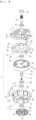
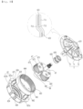
- FIG. 7 is a view showing an example of the power transmission unit 6.
- the power transmission unit 6 includes a housing H, which is secured to the fixing panel 151, an input shaft 64, which is rotatably secured to the bottom surface of the housing H (the surface oriented in a direction toward the rotor), an output shaft 65, which is rotatably secured to the upper surface of the housing H (the surface oriented in a direction toward the fixing panel), and a gear unit, which is provided inside the housing to transmit the rotational motion of the input shaft 64 to the output shaft 65.
- the input shaft 64 may be formed as a shaft that has one end secured to the rotor 52 and an opposite end located inside the housing H
- the output shaft 65 may be formed as a shaft that has one end secured to the rear cover 23 and an opposite end located inside the housing H.
- the housing H It is desirable for the housing H to be secured to the fixing panel 151 and to be disposed in the space (the external space of the cabinet) isolated from the space in which the drum 2 is located (the internal space in the cabinet). The reason for this is to minimize the transfer of heat in the cabinet (heat radiated from the drum or the drying unit) to the inside of the housing H to thus improve the durability of the power transmission unit 6.
- the input shaft 64 may be coupled to the rotor body 521 using the shaft coupling part 54 shown in FIG. 6 .
- the shaft coupling part 54 may include a disc-shaped coupling body 541 and a shaft coupling hole 543, which is formed through the coupling body to allow one end of the input shaft 64 to be coupled thereto.
- the coupling body 541 may be provided with a body protrusion 544, and the rotor body 521 may have a body protrusion through-hole 524 formed therein to allow the body protrusion 544 to be inserted thereinto.
- the coupling body 541 may be further provided with a coupling body bent portion 542.
- the coupling body bent portion 542 may be formed such that the surface of the coupling body 541 that faces the housing H is concavely bent toward the rotor body 521.
- the rotor body 521 may have a bent portion through-hole 525 formed therein to allow the coupling body bent portion 542 to pass therethrough.
- the output shaft 65 may be inserted into the fixing panel through-hole 153 to be connected to the drum 2, and the rear cover 23 may be provided with a shaft bracket 231 (refer to FIG. 4 ), to which the output shaft 65 is secured.
- the reason for this is to disperse the stress applied to the center of the rear cover 23 during rotation of the output shaft 65.
- the housing H may be secured to the fixing panel 151 using a transmission unit bracket 61 and a housing coupling part 612.
- the transmission unit bracket 61 may have a bracket through-hole 611 to allow the output shaft 65 to pass therethrough, and the housing coupling part 612 may be formed as a bolt that connects the housing H to the transmission unit bracket 61.
- the transmission unit bracket 61 may be made of the same material as the fixing panel 151, or may be made of a material having strength higher than the strength of the fixing panel 151.
- FIG. 4 illustrates the case in which the transmission unit bracket 61 is secured to the surface of the fixing panel 151 that faces the rear cover 23.
- the transmission unit bracket 61 may be secured to the surface facing the cover panel 19 in the space provided by the fixing panel 151.
- the housing H may include a housing body 62, which is formed in a hollow cylindrical shape and has an opening formed in the surface thereof that faces the fixing panel 151, and a housing cover 63, which is secured to the housing body 62 to close the opening.
- the housing body 62 may include an accommodation space 622 in which the gear unit G is mounted.
- the accommodation space 622 may communicate with the outside through the opening.
- the accommodation space 622 may be defined by a housing base 621a, to which the input shaft 64 is secured, and a housing circumferential surface 621b, which extends from the edge of the housing base 621a toward the housing cover 63.
- the housing body 62 may be provided with an input shaft support portion 625, which extends from the housing base 621a toward the rotor 52.
- the input shaft support portion 625 may be formed as a pipe that surrounds an input shaft through-hole 626 formed through the housing body 62. That is, the input shaft through-hole 626 may be formed through the input shaft support portion 625 so as to communicate with the accommodation space 622.
- the input shaft 64 inserted into the input shaft through-hole 626 is rotatably secured to the input shaft support portion 625 using input shaft bearings 628 and 629.
- the input shaft bearings may include a first input shaft bearing 628 and a second input shaft bearing 629, which is fixed in the input shaft through-hole 626 so as to be located between the first input shaft bearing 628 and the rotor 52.
- the free end of the input shaft support portion 625 may be inserted into the coupling body bent portion 542, which is provided at the shaft coupling part 54.
- the length of the input shaft support portion 625 may need to be increased in order to fix the two input shaft bearings 628 and 629.
- the free end of the input shaft support portion 625 is inserted into the coupling body bent portion 542, it is possible to minimize the amount of space that is required for installation of the motor 5 and the power transmission unit 6 (thereby minimizing the volume of the laundry treating apparatus).
- the housing cover 63 may be formed in any of various shapes, so long as the same is capable of opening or closing the opening formed in the housing body 62.
- FIG. 8 illustrates the case in which the housing cover 63 is implemented as a disc-shaped cover body 631.
- the housing cover 63 may be secured to the housing body 62 using a cover-fixing plate 623, which is provided on the housing circumferential surface 621b.
- the housing cover 63 may include an output shaft support portion 635, which extends from the cover body 631 toward the fixing panel 151, an output shaft through-hole 632, which is formed through the output shaft support portion 635 to allow the output shaft 65 to be inserted thereinto, and output shaft bearings 638 and 639, which are provided in the output shaft support portion 635 to rotatably secure the output shaft 65 to the output shaft through-hole 632.
- the housing cover 63 includes a mounting portion 637, which is provided at the cover body 631 and to which the stator 51 is secured.
- the mounting portion 637 may be formed in any of various shapes that allow the stator coupling part (the bolt or the like) to be coupled thereto.
- the drawings illustrate the case in which the mounting portion 637 is formed in a hollow cylindrical shape.
- the mounting portion 637 may be provided in a plural number, and the plurality of mounting portions 637 may be disposed on the circumferential surface of the cover body 631. It is desirable for the stator bracket 515 to be provided in the same number as the number of mounting portions 637.
- the cover-fixing plate 623 When the mounting portions 637 are formed in the shape of a cylinder that protrudes from the cover body 631 toward the rotor 52, it is desirable for the cover-fixing plate 623 to have fixing plate through-holes 624 formed therein to allow the mounting portions 637 to be inserted thereinto. The reason for this is to minimize the outer diameter of the cover-fixing plate 623 (thereby minimizing the amount of space that is required for installation of the housing).
- the cover body 631 may be provided with a bent portion 634, which is formed such that a region including the output shaft through-hole 632 protrudes toward the fixing panel 151.
- the output shaft bearings may include a first output shaft bearing 638 and a second output shaft bearing 639, which are secured to the output shaft support portion 635 and are located in the output shaft through-hole 631.
- the housing cover 63 may further include a seal 633, which is secured to the output shaft support portion 635 to close the output shaft through-hole 632.
- the housing H is secured to the fixing panel 151 via the housing coupling part 612.
- the stator 51 is secured to the housing H by securing the stator coupling part, which is inserted into the coupling part through-hole 516, to the mounting portion 637.
- the rotor 52 is secured to the housing H using the input shaft 64. That is, since the stator 51 and the rotor 52 are secured to the housing H (since the stator and the rotor vibrate together with the housing), it is possible to minimize deterioration in coaxiality between the input shaft 64 and the output shaft 65.
- the gear unit G may include a ring gear 66, which is secured to the housing circumferential surface 621b and is located in the accommodation space 622, a driving gear 69, which is secured to the input shaft 64 and is located in the accommodation space 622, a cage 67, which is located in the accommodation space 622 and to which the opposite end of the output shaft 65 is secured, and a driven gear 68, which is rotatably secured to the case 67 to connect the driving gear 69 to the ring gear 66.
- the ring gear 66 may include a gear body 661, which is secured to the housing circumferential surface 621b, and gear teeth 662, which are formed on the inner circumferential surface of the gear body.
- the cage 67 may include a first base 671, which is located in a gear body through-hole 663 (a through-hole defined by the gear teeth) formed through the gear body and to which one end of the output shaft 65 is secured, a second base 672, which is located in the gear body through-hole 663 and has a base through-hole 673 formed in the center thereof, and a connection shaft 675, which connects the first base to the second base and serves as a rotation shaft of the driven gear 68. Since the output shaft 65 is secured to the first base 671, whether the output shaft 65 rotates is determined depending on whether the cage 67 rotates.
- the driven gear 68 may be composed of a plurality of gears.
- the drawings illustrate the case in which the driven gear is composed of a first driven gear 681, a second driven gear 682, and a third driven gear 683.
- the input shaft 64 is inserted into the base through-hole 673, and is disposed coaxially with the output shaft 65.
- the gear teeth of the driving gear 69 are located in the space formed between the driven gears 681, 682, and 683 so as to be engaged with the gear teeth of the driven gears 681, 682, and 683.
- the gear body 661 may have a coupling protrusion accommodation recess 664 formed therein, and the housing base 621a may be provided with a ring gear coupling protrusion 621c, which is inserted into the coupling protrusion accommodation recess 664.
- the housing H may further include a heat insulation part 7.
- the heat insulation part 7 serves to minimize the transfer of external heat to the accommodation space 622 in the housing, and is preferably made of a material having heat conductivity lower than the heat conductivity of the housing H. That is, when the housing body 62 and the housing cover 63 are made of a metallic material, it is desirable for the heat insulation part 7 to be made of a non-metallic material such as plastic.
- the heat insulation part 7 When the housing H is secured to the fixing panel 151 and is located in the external space of the cabinet, it is desirable for the heat insulation part 7 to be made of a material having heat conductivity lower than the heat conductivity of the fixing panel 151.
- the heat insulation part 7 may be provided so as to surround the entire area of the housing H, or may be provided only in the region of the housing H that faces the fixing panel 151.
- FIG. 10 illustrates the case in which the heat insulation part 7 is provided only on the housing cover 63 (the region facing the fixing panel).
- the heat insulation part 7 may be formed integrally with the housing cover 631.
- the heat insulation part 7 and the housing cover 63 may be formed through insert injection molding in which a melted material (plastic or the like) is injected into a mold in which the housing cover 63 is accommodated.
- the heat insulation part 7 may include a cover insulation body 71, which is secured to the cover body 631, and a support portion insulation body 72, which surrounds the circumferential surface of the output shaft support portion 635.
- the cover insulation body 71 may include at least one of a first insulation body 711, which is formed on the surface of the cover body 631 that faces the fixing panel 151 in the space provided by the cover body 631, or a second insulation body 712, which is formed on the surface of the cover body 631 that faces the housing body 62 in the space provided by the cover body 631.
- the cover insulation body 71 includes both the first insulation body 711 and the second insulation body 712, it is desirable for the cover insulation body 71 to further include a connection body 713, which passes through the cover body 631 to connect the first insulation body 711 to the second insulation body 712.
- the cover body 631 needs to have a cover through-hole 636 (refer to FIG. 11 ) formed therein to allow the connection body 713 to be located therein.
- the heat insulation part 7 may further include a mounting portion insulation body 73, which surrounds the mounting portion 637.
- the reason for this is to minimize the transfer of heat from the motor 5 to the cover body 631 through the mounting portion 637. It is desirable for the mounting portion insulation body 73 to surround the entire area of the circumferential surface of the mounting portion 637.
- the laundry treating apparatus may further include a stator position setting unit 74.
- the stator position setting unit 74 may include a bracket protrusion 741 (refer to FIG. 5 ), which is formed at the stator bracket 515, and a protrusion accommodation recess 742 (refer to FIG. 9 ), which is formed in the second insulation body 712 to allow the bracket protrusion 741 to be inserted thereinto.
- the heat insulation part may be secured to the fixing panel 151 so as to be located between the housing cover 63 and the fixing panel 151, or may be secured to the fixing panel 151 so as to be located between the fixing panel 151 and the rear cover 23.
- the heat insulation part may surround the fixing panel through-hole 153, and may be formed as a plate having a diameter larger than the diameter of the cover body.
- the gear unit G is located in the accommodation space 622 formed by the housing body 62. That is, the ring gear 66, the driving gear 69, and the driven gear 68 are provided so as to be prevented from escaping the accommodation space 622.
- the reason why the accommodation space 622 is formed only in the housing body 62 is to install the gear unit G as far as possible from the fixing panel 151 (the heat transmission medium radiating the heat in the cabinet to the outside of the cabinet). Accordingly, the laundry treating apparatus 100 is capable of minimizing deterioration in the durability of the gear unit G.
- the laundry treating apparatus 100 may include a damper 9 in order to minimize the risk of separation of the input shaft 64 from the input shaft bearings 628 and 629 or the input shaft support portion 625 due to external force acting on the input shaft 64.
- the damper 9 is provided in the input shaft through-hole 626 so as to be located between the first input shaft bearing 628 and the second input shaft bearing 629, and serves to reduce the transmission of vibration of the first input shaft bearing 628 to the second input shaft bearing 629.
- the damper 9 may be implemented as an elastic body (rubber or the like) that is secured to the circumferential surface of the input shaft 64 and is located between the first input shaft bearing 628 and the second input shaft bearing 629.
- the damper 9 may include a damping body 91, which has a diameter larger than the diameter of the input shaft 64 and smaller than the diameter of the input shaft through-hole 626 (a damping body, which has a diameter smaller than the outer diameter of the input shaft bearing), and a damping body through-hole 92, which is formed through the damping body 91 and into which the input shaft 64 is inserted.
- the input shaft support portion 625 may be further provided with a stopper 627 (a first stopper), which protrudes toward the center of the input shaft through-hole 626 and is located between the first input shaft bearing 628 and the second input shaft bearing 629.
- the first stopper 627 serves to restrict the range within which the first input shaft bearing 628 moves toward the second input shaft bearing 629, or serves to restrict the range within which the second input shaft bearing 629 moves toward the first input shaft bearing 628.
- the damping body 91 is coupled to the circumferential surface of the input shaft 64 (since the damping body is provided so as to rotate together with the input shaft), it is desirable to set the radius of the damping body 91 (the outer radius of the damper) to be shorter than the distance from the center of the input shaft through-hole 626 to the first stopper 627.
- the output shaft support portion 635 may be provided with a stopper 635c (a second stopper), which restricts the movement range of the first output shaft bearing 638 and the movement range of the second output shaft bearing 639.
- the output shaft support portion 635 may include a first mounting portion 635a, in which the first output shaft bearing 638 is located, and a second mounting portion 635b, in which the second output shaft bearing 639 is located.
- the second stopper 635c may be formed as a protrusion that is located between the first mounting portion 635a and the second mounting portion 635b.
- the laundry treating apparatus may further include a heat dissipation part 8.
- the heat dissipation part 8 may include at least one of a first heat dissipation part 81, which is provided at the coupling body 541 to discharge air present between the housing body 62 and the rotor 52 to the outside of the rotor 52, or a second heat dissipation part 82, which is provided on the circumferential surface 621b of the housing body to dissipate the heat in the accommodation space 622 to the outside of the accommodation space 622.
- the first heat dissipation part 81 may be formed as a blade that protrudes from the coupling body 541 toward the housing base 621a.
- the coupling body 541 and the first heat dissipation part 81 rotate, so air present between the rotor 52 and the housing body 62 is discharged to the outside of the rotor 52 through the rotor through-hole 531, with the result that the temperature of the housing H drops.
- FIG. 8 illustrates the case in which the first heat dissipation part 81 is formed as a plurality of blades and the blades are radially disposed about the shaft coupling hole 543. However, only a single blade may be provided at the coupling body 541.
- the first heat dissipation part 81 is formed as a blade extending from the coupling body bent portion 542 to the edge of the coupling body 541. This enables the height of the blade (the length of the blade in a direction from the coupling body toward the housing body) to be increased, thereby achieving an effect of increasing the amount of air that is discharged.
- the second heat dissipation part 82 may be formed as at least one of a housing protruding portion (a cooling fin or the like) that protrudes from the housing circumferential surface 621b or a housing bent portion (a bent recess or the like) that is bent from the housing circumferential surface 621b toward the accommodation space 622.
- the second heat dissipation part 82 serves to increase the surface area of the housing circumferential surface 621b, thereby facilitating heat exchange between the housing body 62 and external air.
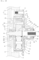
- FIG. 13 shows the inside of the housing body 62.
- the input shaft 64 rotates.
- the driven gears 681, 682, and 683 which are engaged with the driving gear 69, are also rotated. Since the driven gears 681, 682, and 683 are engaged with the ring gear 66, which is secured to the housing body 62, when the driven gears 68 rotate, the cage 67 and the output shaft 65 rotate, and the drum 2, which is secured to the output shaft 65, also rotates.
- a portion of the heat supplied to the drum 2 by the drying unit 3 may be radiated to the outside of the drum 2 (the inside of the cabinet), and the heat in the cabinet may be radiated to the outside of the cabinet. If the heat radiated from the cabinet 1 is transferred to the inside of the housing H of the power transmission unit 6, the durability of the gear unit G may be deteriorated.
- the heat insulation part 7 is capable of minimizing the transfer of heat to the inside of the housing H, thus reducing the risk of deterioration in the durability of the gear unit G.
- the laundry treating apparatus 100 is provided with the first heat dissipation part 81, which is provided at the coupling body 541 connecting the input shaft 64 to the rotor 52, the second heat dissipation part 82, which is provided on the housing circumferential surface 621b, and the motor heat dissipation part 53, which is provided at the rotor, it is possible to minimize the occurrence of the state in which the stator 51 is overheated during rotation of the rotor 52 (during rotation of the drum) and the state in which the accommodation space 622 is overheated.
- laundry treating apparatus may be modified and implemented in various forms, and the scope of the present disclosure is not limited to the embodiments set forth herein.
- the following items represent further aspects of the present invention:
Landscapes
- Engineering & Computer Science (AREA)
- Textile Engineering (AREA)
- Detail Structures Of Washing Machines And Dryers (AREA)
- Main Body Construction Of Washing Machines And Laundry Dryers (AREA)
- Disintegrating Or Milling (AREA)
Abstract
Description
- The present disclosure relates to a laundry treating apparatus.
- "Laundry treating apparatus" is a general term for a washing machine for washing laundry (an object to be washed or an object to be dried), a dryer for drying laundry, and an apparatus capable of both washing and drying laundry.
- The washing machine generally includes a tub, which stores water therein, a washing drum, which is provided in the tub to store laundry therein, and a driving unit (a washing driving unit), which rotates the washing drum. The dryer generally includes a drying drum, which stores laundry therein, a driving unit (a drying driving unit), which rotates the drying drum, and a heat exchange unit, which supplies air to the drying drum to remove moisture from laundry.
- The washing driving unit generally includes a stator, which is secured to the tub to form a rotating magnetic field, a rotor, which is rotated by the rotating magnetic field, and a rotation shaft, which passes through the tub to connect the washing drum to the rotor. The drying driving unit generally includes a motor, a pulley, which is secured to the rotation shaft of the motor, and a belt (a power transmission unit), which transmits the rotational motion of the pulley to the drying drum.
- The washing driving unit is configured such that the rotation shaft of the motor connects the washing drum to the rotor. In order to wash or spin-dry laundry, the washing driving unit needs to increase the rate of rotation of the washing drum or to change the rotation direction of the washing drum. When the rotation shaft of the motor directly connects the washing drum to the rotor, it is possible to easily control the rate of rotation and the rotation direction of the washing drum.
- Meanwhile, the conventional drying driving unit is generally structured such that a power transmission unit, such as a belt, connects the drying drum to the rotation shaft of the motor. The reason why the dryer employs a power transmission unit, such as a belt, in order to rotate the drying drum is that the rate of rotation of the drying drum does not need to be maintained particularly high and that the rotation direction of the drying drum generally does not need to be changed. However, if the dryer is designed so as to be capable of changing the rate of rotation and the rotation direction of the drying drum, movement of laundry in the drying drum may be capable of being controlled, leading to a reduction in the drying time and improvement of drying performance.
- There is disclosed a conventional dryer that includes a drying driving unit connecting a rotor to a drying drum using a speed reducer (
Korean Patent Laid-Open Publication No. 10-2020-0065931 - An object of the present disclosure is to provide a laundry treating apparatus, which includes a power transmission unit configured to connect an input shaft, which is connected to a rotor, and an output shaft, which is connected to a drum, to each other such that the input shaft and the output shaft are disposed coaxially.
- In addition, another object of the present disclosure is to provide a laundry treating apparatus, which is capable of minimizing the transfer of external heat to the inside of the power transmission unit, thereby minimizing deterioration in the durability of the power transmission unit.
- In addition, another object of the present disclosure is to provide a laundry treating apparatus, which includes a means for dissipating heat in the power transmission unit to the outside, thereby minimizing deterioration in the durability of the power transmission unit.
- In addition, another object of the present disclosure is to provide a laundry treating apparatus, which is capable of minimizing deterioration in the durability of bearings supporting the input shaft and the output shaft caused by external force acting on the input shaft and the output shaft during operation of the power transmission unit.
- The present disclosure provides a laundry treating apparatus including a drum in which an object to be dried is accommodated, a drying unit configured to supply heated air to the drum, a fixing panel disposed at a position spaced apart from one surface of the drum, a power transmission unit, which includes a housing secured to the fixing panel, an input shaft having one end located outside the housing and an opposite end located in the housing, an output shaft having one end secured to the one surface of the drum and an opposite end located in the housing, and a gear unit located in the housing to transmit the rotational motion of the input shaft to the output shaft, a motor, which includes a stator secured to the housing to form a rotating magnetic field and a rotor configured to be rotated by the rotating magnetic field and to allow the one end of the input shaft to be secured thereto, and a heat insulation part made of a material having heat conductivity lower than the heat conductivity of the housing to reduce the amount of heat that is transferred from the outside of the housing to the inside thereof.
- In addition, the present disclosure provides a laundry treating apparatus including a drum, which includes a drum body providing a space to store laundry therein, a front cover forming the front surface of the drum body, a rear cover forming the rear surface of the drum body, and a drum introduction opening formed through the front cover to communicate with the inside of the drum body, a drying unit configured to supply heated air to the drum body, a fixing panel disposed at a position spaced apart from the rear cover, a power transmission unit, which includes a housing secured to the fixing panel, an input shaft having one end located outside the housing and an opposite end located in the housing, an output shaft having one end secured to the rear cover and an opposite end located in the housing, and a gear unit located in the housing to transmit the rotational motion of the input shaft to the output shaft, a motor, which includes a stator secured to the fixing panel or the housing to form a rotating magnetic field and a rotor configured to be rotated by the rotating magnetic field and to allow the one end of the input shaft to be secured thereto, and a heat insulation part made of a material having heat conductivity lower than the heat conductivity of the housing to reduce the amount of heat that is transferred from the outside of the housing to the inside thereof.
- The heat insulation part may be located on the surface of the housing that faces the fixing panel.
- The housing may be secured to the fixing panel so as to be located in a space isolated from the space in which the drum is located.
- The heat insulation part may be made of a material having heat conductivity lower than the heat conductivity of the fixing panel.
- The housing may include a housing body, which is formed in a hollow cylindrical shape and has an opening formed in the surface thereof that faces the fixing panel, and a housing cover, which is secured to the housing body to close the opening. The heat insulation part may be provided at the housing cover.
- The housing body and the housing cover may be made of a metallic material, and the heat insulation part may be made of a non-metallic material.
- The housing cover may include a cover body surrounding the opening, an output shaft through-hole formed through the cover body to allow the output shaft to be inserted thereinto, and an output shaft support portion protruding from the cover body toward the fixing panel and surrounding the output shaft through-hole. The heat insulation part may include a cover insulation body secured to the cover body and a support portion insulation body surrounding the circumferential surface of the output shaft support portion.
- The housing cover may further include a bent portion formed such that the region of the cover body in which the output shaft through-hole is formed protrudes toward the fixing panel.
- The housing cover and the cover insulation body may be formed integrally with each other.
- The cover insulation body may include a first insulation body, which is formed on the surface of the cover body that faces the fixing panel in the space provided by the cover body, and a second insulation body, which is formed on the surface of the cover body that faces the housing body in the space provided by the cover body.
- The laundry treating apparatus may further include a cover through-hole formed through the cover body and a connection body inserted into the cover through-hole to connect the first insulation body to the second insulation body.
- The cover insulation body may be secured to the housing cover via insert injection molding.
- The laundry treating apparatus may further include an output shaft bearing, which is provided inside the output shaft support portion to rotatably secure the output shaft to the inside of the output shaft support portion, and a seal, which is secured to the output shaft support portion to prevent the introduction of external air into the output shaft bearing.
- The laundry treating apparatus may further include a mounting portion provided at the cover body to allow the stator to be detachably secured thereto.
- The heat insulation part may further include a mounting portion insulation body surrounding the mounting portion.
- The stator may include a ring-shaped core, a plurality of support bars protruding radially from the outer circumferential surface of the core, a ring-shaped core insulation part surrounding the core, a plurality of support bar insulation parts provided in the core insulation part to surround respective ones of the plurality of support bars, a coil provided in each of the plurality of support bar insulation parts, and a stator bracket provided on the inner circumferential surface of the core insulation part so as to be coupled to the mounting portion.
- The laundry treating apparatus may further include a bracket protrusion formed at the stator bracket and a protrusion accommodation recess formed in the cover insulation body to allow the bracket protrusion to be inserted thereinto.
- The present disclosure provides a laundry treating apparatus including a drum, which includes a drum body providing a space to store laundry therein, a front cover forming the front surface of the drum body, a rear cover forming the rear surface of the drum body, and a drum introduction opening formed through the front cover to communicate with the inside of the drum body, a drying unit configured to supply heated air to the drum body, a fixing panel disposed at a position spaced apart from the rear cover, a power transmission unit, which includes a housing secured to the fixing panel, an input shaft having one end located outside the housing and an opposite end located in the housing, an output shaft having one end secured to the rear cover and an opposite end located in the housing, and a gear unit located in the housing to transmit the rotational motion of the input shaft to the output shaft, a motor, which includes a stator secured to the fixing panel or the housing to form a rotating magnetic field and a rotor configured to be rotated by the rotating magnetic field and to allow the one end of the input shaft to be secured thereto, and a heat insulation part, which is made of a material having heat conductivity lower than the heat conductivity of the fixing panel and the heat conductivity of the housing and is located at a position between the housing and the fixing panel or a position between the fixing panel and the rear cover.
- The present disclosure provides a laundry treating apparatus including a drum, which includes a drum body providing a space to store an object to be dried (laundry or the like) therein, a front cover forming the front surface of the drum body, a rear cover forming the rear surface of the drum body, and a drum introduction opening formed through the front cover to communicate with the inside of the drum body, a drying unit configured to supply heated air to the drum, a fixing panel disposed at a position spaced apart from the rear cover, a housing, which includes a housing body secured to the fixing panel and having formed therein an accommodation space and an opening allowing the accommodation space to communicate with the outside and a housing cover coupled to the housing body to close the opening, an input shaft penetrating the housing body such that one end thereof is located outside the housing and an opposite end thereof is located in the accommodation space, an output shaft penetrating the housing cover such that one end thereof is secured to the rear cover and an opposite end thereof is located in the accommodation space, a ring gear secured to the housing body so as to be located in the accommodation space, a driving gear secured to the input shaft so as to be located in the accommodation space, a cage located in the accommodation space to allow the opposite end of the output shaft to be secured thereto, a driven gear, which is rotatably secured to the cage to connect the driving gear to the ring gear and is located in the accommodation space, and a motor, which includes a stator secured to the fixing panel or the housing to form a rotating magnetic field and a rotor configured to be rotated by the rotating magnetic field and to allow the one end of the input shaft to be secured thereto.
- The housing body may include a housing base, an input shaft through-hole formed through the housing base to allow the input shaft to be inserted thereinto, and a housing circumferential surface extending from the edge of the housing base toward the fixing panel. The accommodation space may be formed by the housing base and the housing circumferential surface.
- The ring gear, the driving gear, and the driven gear may be provided so as to be prevented from escaping the space provided by the accommodation space.
- The housing body may further include a cover-fixing plate provided on the housing circumferential surface to allow the housing cover to be secured thereto.
- The stator may include a ring-shaped core, a plurality of support bars protruding radially from the outer circumferential surface of the core, a ring-shaped core insulation part surrounding the core, a plurality of support bar insulation parts provided in the core insulation part to surround respective ones of the plurality of support bars, a coil provided in each of the plurality of support bar insulation parts, and a stator bracket provided on the inner circumferential surface of the core insulation part so as to be coupled to a mounting portion. The housing cover may further include the mounting portion to which the stator bracket is detachably secured. The cover-fixing plate may have a fixing plate through-hole formed therein to allow the mounting portion to pass therethrough.
- The laundry treating apparatus may further include an input shaft support portion extending from the housing base toward the rotor and surrounding the input shaft through-hole and an input shaft bearing provided in the input shaft support portion to rotatably secure the input shaft to the input shaft support portion.
- The input shaft bearing may include a first input shaft bearing and a second input shaft bearing, which are located in the input shaft support portion.
- The laundry treating apparatus may further include an output shaft through-hole formed through the housing cover to allow the output shaft to be inserted thereinto, an output shaft support portion extending from the housing cover toward the fixing panel and surrounding the output shaft through-hole, an output shaft bearing for securing the output shaft to the output shaft support portion, and a seal provided at the output shaft support portion to prevent the introduction of external air into the output shaft bearing.
- The output shaft bearing may include a first output shaft bearing and a second output shaft bearing, which are located in the output shaft support portion.
- The housing may be located in a space isolated from the space in which the drum is located.
- The laundry treating apparatus may further include a heat insulation part, which is made of a material having heat conductivity lower than the heat conductivity of the housing cover and is secured to the housing cover.
- The housing body and the housing cover may be made of a metallic material, and the heat insulation part may be made of a non-metallic material.
- The present disclosure provides a laundry treating apparatus, which includes a power transmission unit configured to connect an input shaft, which is connected to a rotor, and an output shaft, which is connected to a drum, to each other such that the input shaft and the output shaft are disposed coaxially.
- In addition, the present disclosure provides a laundry treating apparatus, which is capable of minimizing the transfer of external heat to the inside of the power transmission unit, thereby minimizing deterioration in the durability of the power transmission unit.
- In addition, the present disclosure provides a laundry treating apparatus, which includes a means for dissipating heat in the power transmission unit to the outside, thereby minimizing deterioration in the durability of the power transmission unit.
- In addition, the present disclosure provides a laundry treating apparatus, which is capable of minimizing deterioration in the durability of bearings supporting the input shaft and the output shaft caused by external force acting on the input shaft and the output shaft during operation of the power transmission unit.
-
-
FIGs. 1 and2 are views showing an example of a laundry treating apparatus. -
FIGs. 3 and4 are views showing an example of the internal structure of the laundry treating apparatus. -
FIG. 5 is a view showing an example of a stator. -
FIG. 6 is a view showing an example of a rotor. -
FIGs. 7 to 10 are views showing an example of a power transmission unit. -
FIG. 11 is a view showing an example of a heat insulation part. -
FIGs. 12 and13 are views showing the cross-section of the power transmission unit. - Hereinafter, embodiments of a laundry treating apparatus will be described in detail with reference to the accompanying drawings.
-
FIG. 1 is a view showing an example of alaundry treating apparatus 100. Thelaundry treating apparatus 100 may include acabinet 1 and adrum 2, which is rotatably provided inside the cabinet and provides a space for storing laundry (an object to be washed or an object to be dried). As shown inFIG. 2 , adrying unit 3 may be provided inside thecabinet 1 in order to remove moisture from laundry by supplying high-temperature dry air (air having a temperature higher than room temperature or air having dryness higher than the dryness of indoor air) to thedrum 2. - As shown in
FIG. 3 , thecabinet 1 may include afront panel 11, which forms the front surface of the laundry treating apparatus, and abase panel 17, which forms the bottom surface of the laundry treating apparatus. Thefront panel 11 has formed therein anintroduction opening 111, which communicates with thedrum 2. Theintroduction opening 111 may be closed by adoor 113. - A
control panel 115 may be provided on thefront panel 11. Thecontrol panel 115 may include an input unit for receiving a control command from a user and a display for outputting information, such as control commands selectable by the user. The input unit may include a power supply request unit for requesting the supply of power to the laundry treating apparatus, a course input unit for allowing the user to select a desired course from among a plurality of courses, and an execution request unit for requesting commencement of the course selected by the user. - The
drum 2 may be formed in a hollow cylindrical shape.FIG. 2 is a view illustrating the case in which thedrum 2 includes adrum body 21, which has the shape of a cylinder that has an open front surface and an open rear surface, afront cover 22, which forms the front surface of thedrum body 21, and arear cover 23, which forms the rear surface of thedrum body 21. Thefront cover 22 may have formed therein adrum introduction opening 221, through which the inside of thedrum body 21 communicates with the outside, and therear cover 23 may have formed therein anair inlet 233, through which external air flows into thedrum body 21. - As shown in
FIG. 3 , thedrum body 21 may further include alifter 24. Thelifter 24 may be formed such that a board, which extends from thefront cover 22 toward therear cover 23, protrudes from thedrum body 21 toward the rotation center of the drum 2 (protrudes from the circumferential surface of the drum toward the rotation center of the drum). - In the
laundry treating apparatus 100, thedrum 2 may have a drum through-hole, which is formed through thedrum body 21 so that the inside of the drum communicates with the outside of the drum. However, when thelaundry treating apparatus 100 is configured as a laundry drying apparatus, thedrum 2 may not have a drum through-hole therein. - The
drum 2 may be rotatably secured to at least one of a firstbody support part 12 or a secondbody support part 15. The drawings illustrate the case in which therear cover 23 is rotatably secured to the secondbody support part 15 via a motor 5 (a driving unit) and in which thefront cover 22 is rotatably connected to the firstbody support part 12. - The first
body support part 12 may be formed as asupport panel 121, which is secured to thecabinet 1 and is located between thefront panel 11 and thefront cover 22. Thesupport panel 121 may be secured to thebase panel 17, and may be located between thefront panel 11 and thefront cover 22. In this case, the rear surface of the front panel 11 (the surface facing the support panel) may be secured to thesupport panel 121, and the lower end thereof may be secured to thebase panel 17. - The
support panel 121 may include a support panel through-hole 122, a drum connection body 123 (refer toFIG. 2 ) connecting the support panel through-hole 122 to thedrum introduction opening 221, and apanel connection body 125 connecting the support panel through-hole 122 to theintroduction opening 111. The support panel through-hole 122 may be formed through thesupport panel 121 so that the introduction opening 111 communicates with thedrum introduction opening 221. - As shown in
FIG. 2 , thedrum connection body 123 may be formed as a pipe that is secured to the rear surface of the support panel 121 (the surface facing the drum introduction opening in the space provided by the support panel). One end of thedrum connection body 123 may be formed so as to surround the support panel through-hole 122, and the free end of thedrum connection body 123 may be formed so as to support thefront cover 22. That is, the free end of thedrum connection body 123 may be inserted into thedrum introduction opening 221, or may be in contact with the free end of thefront cover 22, which forms thedrum introduction opening 221. -
FIG. 2 illustrates the case in which the free end of thedrum connection body 123 is in contact with the free end of thefront cover 22. In this case, thedrum connection body 123 may be provided with a ring-shapedconnection damper 124. Theconnection damper 124 serves to minimize the risk of separation of the drum introduction opening 221 from the drum connection body 123 (the risk of leakage of air in the drum to the cabinet) when thedrum 2 rotates or vibrates. - The
panel connection body 125 may be formed as a pipe that is secured to the front surface of the support panel 121 (the surface facing the front panel in the space provided by the support panel). One end of thepanel connection body 125 may be formed so as to surround the support panel through-hole 122, and the other end of thepanel connection body 125 may be formed so as to be connected to theintroduction opening 111. Therefore, the laundry supplied to the introduction opening 111 may move to thedrum body 21 through thepanel connection body 125, the support panel through-hole 122, thedrum connection body 123, and thedrum introduction opening 221. - The
support panel 121 may have anexhaust port 126, which is formed through thepanel connection body 125, and afilter 127 may be detachably secured to theexhaust port 126. Thefilter 127 may be formed in any of various structures, so long as the same is capable of removing foreign substances from the air moving from thedrum 2 to theexhaust port 126. - The
support panel 121 may be further provided withdrum support parts drum 2 from sagging. The drum support parts may include afirst roller 128 and asecond roller 129, which are secured to thesupport panel 121 and rotatably support thedrum 2. Although it is illustrated inFIG. 3 that thefirst roller 128 and thesecond roller 129 support thedrum body 21, therollers front cover 22. - The second
body support part 15 may be formed as a fixingpanel 151, which is secured to thecabinet 1 so as to be located at a point spaced apart from therear cover 23.FIG. 4 illustrates the case in which the fixingpanel 151 is secured to thebase panel 17 to form the rear surface of the laundry treating apparatus 100 (the rear surface of the cabinet). - The fixing
panel 151 may have formed therein a driving-unit-mountingrecess 152, which provides a space in which themotor 5 is mounted. The driving-unit-mountingrecess 152 may be formed such that a portion of the fixingpanel 151 is concavely depressed toward therear cover 23 of the drum. The fixingpanel 151 may have a fixing panel through-hole 153 formed therein to allow a shaft (an output shaft) for rotating thedrum 2 to pass therethrough. The fixing panel through-hole 153 may be located within the driving-unit-mountingrecess 152. - As described above, when the
drum 2 includes thedrum body 21, thefront cover 22 secured to the drum body, and therear cover 23 secured to the drum body, the rigidity of the drum is higher than that of a structure in which the open front surface and the open rear surface of thedrum body 21 are rotatably connected to thesupport panel 121 and the fixingpanel 151, respectively. The increase in the rigidity of the drum may minimize deformation of thedrum body 21 during rotation of the drum, thus minimizing a problem in which laundry catches in the space between the drum body and the support panel or in the space between the drum body and the fixing panel due to deformation of the drum body 21 (thereby minimizing the load on the motor). - As shown in
FIG. 2 , the dryingunit 3 may include anexhaust passage 31, which is connected to theexhaust port 126, asupply passage 32, which guides the air in theexhaust passage 31 to thedrum body 21, and aheat exchange unit 34, which is provided inside theexhaust passage 31 to sequentially dehumidify and heat air. - The
exhaust passage 31 may include afirst duct 311, which is connected to theexhaust port 126, asecond duct 312, which is connected to thesupply passage 32, and athird duct 313, which connects thefirst duct 311 to thesecond duct 312. Thethird duct 313 may be secured to thebase panel 17. - The
heat exchange unit 34 may be implemented as any of various devices, so long as the same is capable of sequentially dehumidifying and heating the air introduced into theexhaust passage 31.FIG. 2 illustrates the case in which theheat exchange unit 34 is implemented as a heat pump. That is, theheat exchange unit 34 includes a first heat exchanger 341 (a heat-absorbing part), which removes moisture from the air introduced into theexhaust passage 31, a second heat exchanger 343 (a heat-generating part), which is provided inside theexhaust passage 31 to heat the air that has passed through the heat-absorbingpart 341, and afan 349, which causes the air discharged from thedrum 2 to sequentially pass through the heat-absorbing part and the heat-generating part and then to move to thesupply duct 32. - The heat-absorbing
part 341 and the heat-generatingpart 343 are sequentially disposed in the direction in which air flows, and are connected to each other via arefrigerant pipe 348, which forms a circulation path of the refrigerant. The refrigerant is moved along therefrigerant pipe 348 by acompressor 345, which is located outside theexhaust passage 31, and therefrigerant pipe 348 is provided with apressure regulator 347 for controlling the pressure of the refrigerant. - As shown in
FIG. 4 , theair inlet 233, which is provided in therear cover 23 of the drum, may be composed of a plurality of holes, which are disposed around the center of the rear cover 23 (the rotation center of the drum). In this case, thesupply passage 32 may include asupply duct 321, which is provided in the fixingpanel 151 to form a passage along which the air discharged from thesecond duct 312 moves, and a first passage-formingpart 323 and a second passage-formingpart 324, which guide the air in thesupply duct 321 to theair inlet 233. - The
supply duct 321 may be formed such that a portion of the fixingpanel 151 is bent in a direction away from therear cover 23 to form a passage (an air movement passage). In addition, thesupply duct 321 may be formed in the shape of a ring that surrounds the driving-unit-mountingrecess 152, and thesecond duct 312 may be formed so as to be connected to the circumferential surface of thesupply duct 321. - The first passage-forming
part 323 may be provided so as to surround the outer circumferential surface of the ring formed by the holes of theair inlet 233, and the second passage-formingpart 324 may be provided so as to surround the inner circumferential surface of the ring formed by the holes of theair inlet 233. - The first passage-forming
part 323 and the second passage-formingpart 324 may be secured to therear cover 23, or may be secured to thesupply duct 321.FIG. 4 illustrates the case in which the passage-formingparts rear cover 23. In the case illustrated inFIG. 4 , the free end of the first passage-formingpart 323 surrounds the outer circumferential surface of the passage (the ring-shaped passage) formed by thesupply duct 321, and the free end of the second passage-formingpart 324 surrounds the inner circumferential surface of the passage formed by thesupply duct 321. The first passage-formingpart 323 and the second passage-formingpart 324 may be made of rubber, felt, or the like. - The
motor 5 for rotating thedrum 2 includes astator 51, which is located in the driving-unit-mountingrecess 152 to form a rotating magnetic field, and arotor 52, which is rotated by the rotating magnetic field. The rotational motion of therotor 52 is transmitted to thedrum 2 via apower transmission unit 6, which is secured to the fixingpanel 151, and thestator 51 is secured to at least one of the fixingpanel 151 or thepower transmission unit 6. The structure in which thestator 51 is secured to thepower transmission unit 6 is advantageous from the aspect of maintenance of coaxiality between aninput shaft 64 and anoutput shaft 65, which are included in the power transmission unit 6 (consequently minimizing vibration of the laundry treating apparatus during rotation of the drum and minimizing deterioration in the durability of the power transmission unit). - In order to prevent the
motor 5, which is provided in the driving-unit-mountingrecess 152, from being exposed to the outside (in order to improve the durability of the motor and to prevent accidents by preventing the motor from being exposed to the external environment), the fixingpanel 151 may be further provided with acover panel 19 for preventing themotor 5 from being exposed to the outside. Further, thecover panel 19 may be formed in a shape that is also capable of preventing thesupply duct 321 from being exposed to the outside (a shape surrounding the supply duct). The reason for this is not only to minimize radiation of heat to the outside of thesupply duct 321, but also to prevent an accident, which may be caused by contact of the user's body with thesupply duct 321. - As shown in
FIG. 5 , thestator 51 may include a core 511 (a ring-shaped core), which has a through-hole 511b (a core through-hole) formed in the center thereof, a plurality ofsupport bars 511a, which protrude radially from the outer circumferential surface of thecore 511, acore insulation part 512, which insulates the core and has a ring shape, a plurality of supportbar insulation parts 514, which are provided in thecore insulation part 512 to surround the support bars, and coils (not shown), which are provided in the supportbar insulation parts 514. - The
core insulation part 512 is formed in the shape of a ring that has an insulation part through-hole 513 formed in the center thereof to form a space in which thecore 511 is accommodated. For ease of assembly, thecore insulation part 512 may include afirst insulation body 512a and asecond insulation body 512b. In this case, the supportbar insulation parts 514 may include first support bar insulation parts, which are provided in thefirst insulation body 512a, and second support bar insulation parts, which are provided in thesecond insulation body 512b. - The
core insulation part 512 may be provided with astator bracket 515. Thestator bracket 515 may include a plurality of brackets, which protrude from the inner circumferential surface of thecore insulation part 512 toward the center of the insulation part through-hole 513. When thecore insulation part 512 includes thefirst insulation body 512a and thesecond insulation body 512b, thestator bracket 515 may includefirst brackets 515a, which are provided in the first insulation body, andsecond brackets 515b, which are provided in the second insulation body and are coupled to thefirst brackets 515a. - The
stator bracket 515 may be secured to thepower transmission unit 6 using a stator coupling part such as a bolt. To this end, thestator bracket 515 may have a coupling part through-hole 516 formed therein. - As shown in
FIG. 6 , therotor 52 may include arotor body 521, a rotorcircumferential surface 522, which extends from the edge of therotor body 521 toward the fixingpanel 515 to form a space in which thestator 51 is accommodated, and a plurality ofpermanent magnets 523, which are secured to the rotorcircumferential surface 522 such that N-poles and S-poles thereof are alternately exposed. - The
motor 5 may further include a motor heat dissipation part 53, which dissipates the heat generated from thestator 51 to the outside of therotor 52. The motor heat dissipation part 53 may include a plurality of rotor through-holes 531, which are formed through therotor body 521, and a plurality ofrotor blades 533, which are provided at therotor body 521 to form airflow for inducing the air in the rotor to move to the rotor through-holes 531. - Each rotor through-
hole 531 may be formed as a slit that extends from the center of therotor body 521 toward the rotorcircumferential surface 522, and eachrotor blade 533 may be formed as a plate that protrudes from therotor body 521 toward the fixingpanel 151. In this case, it is desirable for eachrotor blade 533 to extend from the center of therotor body 521 toward the rotorcircumferential surface 522. The rotor through-holes 531, each of which is formed as a slit, may be radially disposed about the center of the rotor body 521 (the input shaft), and each of therotor blades 533 may be fixed to the edge of a respective one of the rotor through-holes 531. -
FIG. 7 is a view showing an example of thepower transmission unit 6. Thepower transmission unit 6 includes a housing H, which is secured to the fixingpanel 151, aninput shaft 64, which is rotatably secured to the bottom surface of the housing H (the surface oriented in a direction toward the rotor), anoutput shaft 65, which is rotatably secured to the upper surface of the housing H (the surface oriented in a direction toward the fixing panel), and a gear unit, which is provided inside the housing to transmit the rotational motion of theinput shaft 64 to theoutput shaft 65. Theinput shaft 64 may be formed as a shaft that has one end secured to therotor 52 and an opposite end located inside the housing H, and theoutput shaft 65 may be formed as a shaft that has one end secured to therear cover 23 and an opposite end located inside the housing H. - It is desirable for the housing H to be secured to the fixing
panel 151 and to be disposed in the space (the external space of the cabinet) isolated from the space in which thedrum 2 is located (the internal space in the cabinet). The reason for this is to minimize the transfer of heat in the cabinet (heat radiated from the drum or the drying unit) to the inside of the housing H to thus improve the durability of thepower transmission unit 6. - The
input shaft 64 may be coupled to therotor body 521 using theshaft coupling part 54 shown inFIG. 6 . Theshaft coupling part 54 may include a disc-shapedcoupling body 541 and ashaft coupling hole 543, which is formed through the coupling body to allow one end of theinput shaft 64 to be coupled thereto. - In order to facilitate assembly of the
coupling body 541 and therotor body 521, thecoupling body 541 may be provided with abody protrusion 544, and therotor body 521 may have a body protrusion through-hole 524 formed therein to allow thebody protrusion 544 to be inserted thereinto. - Furthermore, in order to increase the strength of the
coupling body 541, thecoupling body 541 may be further provided with a coupling body bentportion 542. The coupling body bentportion 542 may be formed such that the surface of thecoupling body 541 that faces the housing H is concavely bent toward therotor body 521. In this case, therotor body 521 may have a bent portion through-hole 525 formed therein to allow the coupling body bentportion 542 to pass therethrough. - The
output shaft 65 may be inserted into the fixing panel through-hole 153 to be connected to thedrum 2, and therear cover 23 may be provided with a shaft bracket 231 (refer toFIG. 4 ), to which theoutput shaft 65 is secured. The reason for this is to disperse the stress applied to the center of therear cover 23 during rotation of theoutput shaft 65. - In order to prevent sagging of the housing H and to minimize deformation of the driving-unit-mounting
recess 152, the housing H may be secured to the fixingpanel 151 using atransmission unit bracket 61 and ahousing coupling part 612. - As shown in
FIG. 4 , thetransmission unit bracket 61 may have a bracket through-hole 611 to allow theoutput shaft 65 to pass therethrough, and thehousing coupling part 612 may be formed as a bolt that connects the housing H to thetransmission unit bracket 61. Thetransmission unit bracket 61 may be made of the same material as the fixingpanel 151, or may be made of a material having strength higher than the strength of the fixingpanel 151. -
FIG. 4 illustrates the case in which thetransmission unit bracket 61 is secured to the surface of the fixingpanel 151 that faces therear cover 23. However, thetransmission unit bracket 61 may be secured to the surface facing thecover panel 19 in the space provided by the fixingpanel 151. - As shown in
FIG. 8 , the housing H may include ahousing body 62, which is formed in a hollow cylindrical shape and has an opening formed in the surface thereof that faces the fixingpanel 151, and ahousing cover 63, which is secured to thehousing body 62 to close the opening. - The
housing body 62 may include anaccommodation space 622 in which the gear unit G is mounted. Theaccommodation space 622 may communicate with the outside through the opening. Theaccommodation space 622 may be defined by ahousing base 621a, to which theinput shaft 64 is secured, and a housing circumferential surface 621b, which extends from the edge of thehousing base 621a toward thehousing cover 63. - As shown in
FIG. 9 , thehousing body 62 may be provided with an inputshaft support portion 625, which extends from thehousing base 621a toward therotor 52. The inputshaft support portion 625 may be formed as a pipe that surrounds an input shaft through-hole 626 formed through thehousing body 62. That is, the input shaft through-hole 626 may be formed through the inputshaft support portion 625 so as to communicate with theaccommodation space 622. - The
input shaft 64 inserted into the input shaft through-hole 626 is rotatably secured to the inputshaft support portion 625 usinginput shaft bearings hole 626 so as to be located between the first input shaft bearing 628 and therotor 52. - The free end of the input
shaft support portion 625 may be inserted into the coupling body bentportion 542, which is provided at theshaft coupling part 54. The length of the inputshaft support portion 625 may need to be increased in order to fix the twoinput shaft bearings shaft support portion 625 is inserted into the coupling body bentportion 542, it is possible to minimize the amount of space that is required for installation of themotor 5 and the power transmission unit 6 (thereby minimizing the volume of the laundry treating apparatus). - The
housing cover 63 may be formed in any of various shapes, so long as the same is capable of opening or closing the opening formed in thehousing body 62.FIG. 8 illustrates the case in which thehousing cover 63 is implemented as a disc-shapedcover body 631. Thehousing cover 63 may be secured to thehousing body 62 using a cover-fixingplate 623, which is provided on the housing circumferential surface 621b. - The
housing cover 63 may include an outputshaft support portion 635, which extends from thecover body 631 toward the fixingpanel 151, an output shaft through-hole 632, which is formed through the outputshaft support portion 635 to allow theoutput shaft 65 to be inserted thereinto, andoutput shaft bearings shaft support portion 635 to rotatably secure theoutput shaft 65 to the output shaft through-hole 632. - The
housing cover 63 includes a mountingportion 637, which is provided at thecover body 631 and to which thestator 51 is secured. The mountingportion 637 may be formed in any of various shapes that allow the stator coupling part (the bolt or the like) to be coupled thereto. The drawings illustrate the case in which the mountingportion 637 is formed in a hollow cylindrical shape. - The mounting
portion 637 may be provided in a plural number, and the plurality of mountingportions 637 may be disposed on the circumferential surface of thecover body 631. It is desirable for thestator bracket 515 to be provided in the same number as the number of mountingportions 637. - When the mounting
portions 637 are formed in the shape of a cylinder that protrudes from thecover body 631 toward therotor 52, it is desirable for the cover-fixingplate 623 to have fixing plate through-holes 624 formed therein to allow the mountingportions 637 to be inserted thereinto. The reason for this is to minimize the outer diameter of the cover-fixing plate 623 (thereby minimizing the amount of space that is required for installation of the housing). - In order to increase the strength of the
housing cover 63, thecover body 631 may be provided with abent portion 634, which is formed such that a region including the output shaft through-hole 632 protrudes toward the fixingpanel 151. - The output shaft bearings may include a first output shaft bearing 638 and a second output shaft bearing 639, which are secured to the output
shaft support portion 635 and are located in the output shaft through-hole 631. In addition, in order to prevent external air from being supplied to theoutput shaft bearings housing cover 63 may further include aseal 633, which is secured to the outputshaft support portion 635 to close the output shaft through-hole 632. - The housing H is secured to the fixing
panel 151 via thehousing coupling part 612. Thestator 51 is secured to the housing H by securing the stator coupling part, which is inserted into the coupling part through-hole 516, to the mountingportion 637. Therotor 52 is secured to the housing H using theinput shaft 64. That is, since thestator 51 and therotor 52 are secured to the housing H (since the stator and the rotor vibrate together with the housing), it is possible to minimize deterioration in coaxiality between theinput shaft 64 and theoutput shaft 65. - The gear unit G may include a
ring gear 66, which is secured to the housing circumferential surface 621b and is located in theaccommodation space 622, adriving gear 69, which is secured to theinput shaft 64 and is located in theaccommodation space 622, acage 67, which is located in theaccommodation space 622 and to which the opposite end of theoutput shaft 65 is secured, and a drivengear 68, which is rotatably secured to thecase 67 to connect thedriving gear 69 to thering gear 66. - As shown in
FIG. 9 , thering gear 66 may include agear body 661, which is secured to the housing circumferential surface 621b, andgear teeth 662, which are formed on the inner circumferential surface of the gear body. - The
cage 67 may include afirst base 671, which is located in a gear body through-hole 663 (a through-hole defined by the gear teeth) formed through the gear body and to which one end of theoutput shaft 65 is secured, asecond base 672, which is located in the gear body through-hole 663 and has a base through-hole 673 formed in the center thereof, and aconnection shaft 675, which connects the first base to the second base and serves as a rotation shaft of the drivengear 68. Since theoutput shaft 65 is secured to thefirst base 671, whether theoutput shaft 65 rotates is determined depending on whether thecage 67 rotates. - The driven
gear 68 may be composed of a plurality of gears. The drawings illustrate the case in which the driven gear is composed of a first drivengear 681, a second drivengear 682, and a third drivengear 683. Theinput shaft 64 is inserted into the base through-hole 673, and is disposed coaxially with theoutput shaft 65. The gear teeth of thedriving gear 69 are located in the space formed between the driven gears 681, 682, and 683 so as to be engaged with the gear teeth of the driven gears 681, 682, and 683. - As shown in
FIG. 10 , in order to facilitate coupling or assembly of thering gear 66 and thehousing body 62, thegear body 661 may have a couplingprotrusion accommodation recess 664 formed therein, and thehousing base 621a may be provided with a ringgear coupling protrusion 621c, which is inserted into the couplingprotrusion accommodation recess 664. - In order to increase the durability of the gear unit G, the housing H may further include a
heat insulation part 7. Theheat insulation part 7 serves to minimize the transfer of external heat to theaccommodation space 622 in the housing, and is preferably made of a material having heat conductivity lower than the heat conductivity of the housing H. That is, when thehousing body 62 and thehousing cover 63 are made of a metallic material, it is desirable for theheat insulation part 7 to be made of a non-metallic material such as plastic. - When the housing H is secured to the fixing
panel 151 and is located in the external space of the cabinet, it is desirable for theheat insulation part 7 to be made of a material having heat conductivity lower than the heat conductivity of the fixingpanel 151. - The
heat insulation part 7 may be provided so as to surround the entire area of the housing H, or may be provided only in the region of the housing H that faces the fixingpanel 151.FIG. 10 illustrates the case in which theheat insulation part 7 is provided only on the housing cover 63 (the region facing the fixing panel). - As shown in
FIG. 11 , theheat insulation part 7 may be formed integrally with thehousing cover 631. In one example, theheat insulation part 7 and thehousing cover 63 may be formed through insert injection molding in which a melted material (plastic or the like) is injected into a mold in which thehousing cover 63 is accommodated. - The
heat insulation part 7 may include acover insulation body 71, which is secured to thecover body 631, and a supportportion insulation body 72, which surrounds the circumferential surface of the outputshaft support portion 635. As shown inFIG. 10 , thecover insulation body 71 may include at least one of afirst insulation body 711, which is formed on the surface of thecover body 631 that faces the fixingpanel 151 in the space provided by thecover body 631, or asecond insulation body 712, which is formed on the surface of thecover body 631 that faces thehousing body 62 in the space provided by thecover body 631. - When the
cover insulation body 71 includes both thefirst insulation body 711 and thesecond insulation body 712, it is desirable for thecover insulation body 71 to further include aconnection body 713, which passes through thecover body 631 to connect thefirst insulation body 711 to thesecond insulation body 712. In this case, thecover body 631 needs to have a cover through-hole 636 (refer toFIG. 11 ) formed therein to allow theconnection body 713 to be located therein. - As shown in
FIG. 11 , theheat insulation part 7 may further include a mountingportion insulation body 73, which surrounds the mountingportion 637. The reason for this is to minimize the transfer of heat from themotor 5 to thecover body 631 through the mountingportion 637. It is desirable for the mountingportion insulation body 73 to surround the entire area of the circumferential surface of the mountingportion 637. - In order to facilitate coupling of the
stator 51 and the mountingportion 637, the laundry treating apparatus may further include a statorposition setting unit 74. The statorposition setting unit 74 may include a bracket protrusion 741 (refer toFIG. 5 ), which is formed at thestator bracket 515, and a protrusion accommodation recess 742 (refer toFIG. 9 ), which is formed in thesecond insulation body 712 to allow thebracket protrusion 741 to be inserted thereinto. - Unlike the above description, the heat insulation part may be secured to the fixing
panel 151 so as to be located between thehousing cover 63 and the fixingpanel 151, or may be secured to the fixingpanel 151 so as to be located between the fixingpanel 151 and therear cover 23. In this case, the heat insulation part may surround the fixing panel through-hole 153, and may be formed as a plate having a diameter larger than the diameter of the cover body. - In the
power transmission unit 6 having the above-described structure, the gear unit G is located in theaccommodation space 622 formed by thehousing body 62. That is, thering gear 66, thedriving gear 69, and the drivengear 68 are provided so as to be prevented from escaping theaccommodation space 622. The reason why theaccommodation space 622 is formed only in thehousing body 62 is to install the gear unit G as far as possible from the fixing panel 151 (the heat transmission medium radiating the heat in the cabinet to the outside of the cabinet). Accordingly, thelaundry treating apparatus 100 is capable of minimizing deterioration in the durability of the gear unit G. - Meanwhile, in the
power transmission unit 6 having the above-described structure, when thedriving gear 69 and the drivengear 68 rotate, repulsive force acting between the gears is transmitted to theinput shaft 64 and theoutput shaft 65. That is, when the driving gear and the driven gear rotate, external force acting in a direction away from the housing H or in a direction toward the inside of the housing H is input to theinput shaft 64 and theoutput shaft 65. The above-described operation is more effectively realized when the driving gear, the driven gear, and the ring gear are implemented as helical gears. - As shown in
FIG. 12 , thelaundry treating apparatus 100 may include adamper 9 in order to minimize the risk of separation of theinput shaft 64 from theinput shaft bearings shaft support portion 625 due to external force acting on theinput shaft 64. - The
damper 9 is provided in the input shaft through-hole 626 so as to be located between the first input shaft bearing 628 and the second input shaft bearing 629, and serves to reduce the transmission of vibration of the first input shaft bearing 628 to the secondinput shaft bearing 629. - The
damper 9 may be implemented as an elastic body (rubber or the like) that is secured to the circumferential surface of theinput shaft 64 and is located between the first input shaft bearing 628 and the secondinput shaft bearing 629. As shown inFIG. 8 , thedamper 9 may include a dampingbody 91, which has a diameter larger than the diameter of theinput shaft 64 and smaller than the diameter of the input shaft through-hole 626 (a damping body, which has a diameter smaller than the outer diameter of the input shaft bearing), and a damping body through-hole 92, which is formed through the dampingbody 91 and into which theinput shaft 64 is inserted. - As shown in
FIG. 12 , in order to minimize vibration of the housing H, it is desirable that one surface of the dampingbody 91 be in contact with the first input shaft bearing 628 and that the other surface of the dampingbody 91 be in contact with the secondinput shaft bearing 629. - Furthermore, the input
shaft support portion 625 may be further provided with a stopper 627 (a first stopper), which protrudes toward the center of the input shaft through-hole 626 and is located between the first input shaft bearing 628 and the secondinput shaft bearing 629. Thefirst stopper 627 serves to restrict the range within which the first input shaft bearing 628 moves toward the second input shaft bearing 629, or serves to restrict the range within which the second input shaft bearing 629 moves toward the firstinput shaft bearing 628. - Since the damping
body 91 is coupled to the circumferential surface of the input shaft 64 (since the damping body is provided so as to rotate together with the input shaft), it is desirable to set the radius of the damping body 91 (the outer radius of the damper) to be shorter than the distance from the center of the input shaft through-hole 626 to thefirst stopper 627. - In order to minimize the problem of separation of the
output shaft bearings output shaft 65, the outputshaft support portion 635 may be provided with astopper 635c (a second stopper), which restricts the movement range of the first output shaft bearing 638 and the movement range of the secondoutput shaft bearing 639. As shown inFIG. 11 , the outputshaft support portion 635 may include a first mountingportion 635a, in which the first output shaft bearing 638 is located, and a second mountingportion 635b, in which the second output shaft bearing 639 is located. Thesecond stopper 635c may be formed as a protrusion that is located between the first mountingportion 635a and the second mountingportion 635b. - In order to minimize the transfer of heat to the inside of the housing H and to dissipate heat from the housing H to the outside, the laundry treating apparatus may further include a heat dissipation part 8. As shown in
FIG. 8 , the heat dissipation part 8 may include at least one of a firstheat dissipation part 81, which is provided at thecoupling body 541 to discharge air present between thehousing body 62 and therotor 52 to the outside of therotor 52, or a secondheat dissipation part 82, which is provided on the circumferential surface 621b of the housing body to dissipate the heat in theaccommodation space 622 to the outside of theaccommodation space 622. - The first
heat dissipation part 81 may be formed as a blade that protrudes from thecoupling body 541 toward thehousing base 621a. When therotor 52 rotates, thecoupling body 541 and the firstheat dissipation part 81 rotate, so air present between therotor 52 and thehousing body 62 is discharged to the outside of therotor 52 through the rotor through-hole 531, with the result that the temperature of the housing H drops. -
FIG. 8 illustrates the case in which the firstheat dissipation part 81 is formed as a plurality of blades and the blades are radially disposed about theshaft coupling hole 543. However, only a single blade may be provided at thecoupling body 541. - Meanwhile, when the
coupling body 541 is provided with the coupling body bentportion 542, it is desirable for the firstheat dissipation part 81 to be formed as a blade extending from the coupling body bentportion 542 to the edge of thecoupling body 541. This enables the height of the blade (the length of the blade in a direction from the coupling body toward the housing body) to be increased, thereby achieving an effect of increasing the amount of air that is discharged. - The second
heat dissipation part 82 may be formed as at least one of a housing protruding portion (a cooling fin or the like) that protrudes from the housing circumferential surface 621b or a housing bent portion (a bent recess or the like) that is bent from the housing circumferential surface 621b toward theaccommodation space 622. The secondheat dissipation part 82 serves to increase the surface area of the housing circumferential surface 621b, thereby facilitating heat exchange between thehousing body 62 and external air. - Hereinafter, the operation process of the above-described
power transmission unit 6 will be described with reference toFIG. 13 . -
FIG. 13 shows the inside of thehousing body 62. When therotor 52 rotates, theinput shaft 64 rotates. When thedriving gear 69 is rotated by theinput shaft 64, the driven gears 681, 682, and 683, which are engaged with thedriving gear 69, are also rotated. Since the driven gears 681, 682, and 683 are engaged with thering gear 66, which is secured to thehousing body 62, when the driven gears 68 rotate, thecage 67 and theoutput shaft 65 rotate, and thedrum 2, which is secured to theoutput shaft 65, also rotates. - A portion of the heat supplied to the
drum 2 by the dryingunit 3 may be radiated to the outside of the drum 2 (the inside of the cabinet), and the heat in the cabinet may be radiated to the outside of the cabinet. If the heat radiated from thecabinet 1 is transferred to the inside of the housing H of thepower transmission unit 6, the durability of the gear unit G may be deteriorated. However, in thelaundry treating apparatus 100, theheat insulation part 7 is capable of minimizing the transfer of heat to the inside of the housing H, thus reducing the risk of deterioration in the durability of the gear unit G. - In addition, since the
laundry treating apparatus 100 is provided with the firstheat dissipation part 81, which is provided at thecoupling body 541 connecting theinput shaft 64 to therotor 52, the secondheat dissipation part 82, which is provided on the housing circumferential surface 621b, and the motor heat dissipation part 53, which is provided at the rotor, it is possible to minimize the occurrence of the state in which thestator 51 is overheated during rotation of the rotor 52 (during rotation of the drum) and the state in which theaccommodation space 622 is overheated. - The above-described laundry treating apparatus may be modified and implemented in various forms, and the scope of the present disclosure is not limited to the embodiments set forth herein.
The following items represent further aspects of the present invention: - 1. A laundry treating apparatus comprising:
- a drum (2) comprising a drum body (21) providing a space to store laundry therein, a front cover (22) forming a front surface of the drum body (21), a rear cover (23) forming a rear surface of the drum body (21), and a drum introduction opening (221) formed through the front cover (22) to communicate with an inside of the drum body (21);
- a drying unit (3) configured to supply heated air to the drum body (21);
- a fixing panel (151) disposed at a position spaced apart from the rear cover (23);
- a power transmission unit (6) comprising a housing (H) secured to the fixing panel (151), an input shaft (64) having one end located outside the housing (H) and an opposite end located in the housing (H), an output shaft (65) having one end secured to the rear cover (23) and an opposite end located in the housing (H), and a gear unit (G) located in the housing (H) to transmit rotational motion of the input shaft (64) to the output shaft (65);
- a motor (5) comprising a stator (51) secured to the fixing panel (151) or the housing (H) to form a rotating magnetic field and a rotor (52) configured to be rotated by the rotating magnetic field and to allow the one end of the input shaft (64) to be secured thereto; and
- a heat insulation part (7) made of a material having heat conductivity lower than heat conductivity of the housing (H) to reduce an amount of heat that is transferred from an outside of the housing (H) to an inside of the housing (H).
- 2. The laundry treating apparatus of
item 1, wherein the heat insulation part (7) is located on a surface of the housing (H) that faces the fixing panel (151). - 3. The laundry treating apparatus of
item - 4. The laundry treating apparatus of any one of
items 1 to 3, wherein the heat insulation part (7) is made of a material having heat conductivity lower than heat conductivity of the fixing panel (151). - 5. The laundry treating apparatus of any one of
items 1 to 4, wherein the housing (H) comprises:- a housing body (62) formed in a hollow cylindrical shape, the housing body (62) having an opening formed in a surface thereof that faces the fixing panel (151); and
- a housing cover (63) secured to the housing body (62) to close the opening, and
- wherein the heat insulation part (7) is provided at the housing cover (63).
- 6. The laundry treating apparatus of
item 5, wherein the housing body (62) and the housing cover (63) are made of a metallic material, and the heat insulation part (7) is made of a non-metallic material. - 7. The laundry treating apparatus of
item - a cover body (631) surrounding the opening;
- an output shaft through-hole (632) formed through the cover body (631) to allow the output shaft (65) to be inserted thereinto; and
- an output shaft support portion (635) protruding from the cover body (631) toward the fixing panel (151) and surrounding the output shaft through-hole (632), and
- wherein the heat insulation part (7) comprises:
- a cover insulation body (71) secured to the cover body (631); and
- a support portion insulation body (72) surrounding a circumferential surface of the output shaft support portion (635).
- 8. The laundry treating apparatus of
item 7, wherein the housing cover (63) further comprises a bent portion (542) formed such that a region of the cover body (631) in which the output shaft through-hole (632) is formed protrudes toward the fixing panel (151);
and/or
wherein the housing cover (63) and the cover insulation body (71) are formed integrally with each other. - 9. The laundry treating apparatus of
item 7 or 8, wherein the cover insulation body (71) comprises:- a first insulation body (711) formed on a surface of the cover body (631) that faces the fixing panel (151) in a space provided by the cover body (631); and
- a second insulation body (712) formed on a surface of the cover body (631) that faces the housing (H) body in a space provided by the cover body (631).
- 10. The laundry treating apparatus of
item 9, further comprising:- a cover through-hole (636) formed through the cover body (631); and
- a connection body (713) inserted into the cover through-hole (636) to connect the first insulation body (711) to the second insulation body (712);
- and preferably
- wherein the cover insulation body (71) is secured to the housing cover (62) via insert injection molding.
- 11. The laundry treating apparatus of any one of
items 7 to 10, further comprising:- an output shaft bearing (638, 639) provided inside the output shaft support portion (635) to rotatably secure the output shaft (65) to an inside of the output shaft support portion (635); and
- a seal (633) secured to the output shaft support portion (635) to prevent introduction of external air into the output shaft bearing (638, 639).
- 12. The laundry treating apparatus of any one of
items 7 to 11, further comprising:- a mounting portion (637) provided at the cover body (631) to allow the stator (51) to be detachably secured thereto;
- and preferably
- wherein the heat insulation part (7) further comprises a mounting portion insulation body (73) surrounding the mounting portion (637).
- 13. The laundry treating apparatus of
item 12, wherein the stator (51) comprises:- a ring-shaped core (511);
- a plurality of support bars (511a) protruding radially from an outer circumferential surface of the core (511);
- a ring-shaped core insulation part (512) surrounding the core (511);
- a plurality of support bar insulation parts (514) provided in the core insulation part (512) to surround respective ones of the plurality of support bars (511a);
- a coil provided in each of the plurality of support bar insulation parts (514); and
- a stator bracket (515) provided on an inner circumferential surface of the core insulation part (512) so as to be coupled to the mounting portion (637).
- 14. The laundry treating apparatus of item 13, further comprising:
- a bracket protrusion (741) formed at the stator bracket (515); and
- a protrusion accommodation recess (742) formed in the cover insulation body (71) to allow the bracket protrusion (741) to be inserted thereinto.
- 15. A laundry treating apparatus comprising:
- a drum (2) comprising a drum body (21) providing a space to store laundry therein, a front cover (22) forming a front surface of the drum body (21), a rear cover (23) forming a rear surface of the drum body (21), and a drum introduction opening (221) formed through the front cover (22) to communicate with an inside of the drum body (21);
- a drying unit (3) configured to supply heated air to the drum body (21);
- a fixing panel (151) disposed at a position spaced apart from the rear cover (23);
- a power transmission unit (6) comprising a housing (H) secured to the fixing panel (151), an input shaft (64) having one end located outside the housing (H) and an opposite end located in the housing (H), an output shaft (65) having one end secured to the rear cover (23) and an opposite end located in the housing (H), and a gear unit (G) located in the housing (H) to transmit rotational motion of the input shaft (64) to the output shaft (65);
- a motor (5) comprising a stator (51) secured to the fixing panel (151) or the housing (H) to form a rotating magnetic field and a rotor (52) configured to be rotated by the rotating magnetic field and to allow the one end of the input shaft (64) to be secured thereto; and
- a heat insulation part (7) made of a material having heat conductivity lower than heat conductivity of the fixing panel (151) and heat conductivity of the housing (H), the heat insulation part (7) being located at a position between the housing (H) and the fixing panel (151) or a position between the fixing panel (151) and the rear cover (23).
Claims (12)
- A laundry treating apparatus comprising:a drum (2) defining a space to receive laundry therein;a drying unit (3) configured to supply heated air to the drum (2);a fixing panel (151) disposed at a position spaced apart from a rear surface of the drum (2);a power transmission unit (6) including:a housing (H) coupled to the fixing panel (151),an input shaft (64) having one end disposed at an outside of the housing (H) and an opposite end disposed in the housing (H),an output shaft (65) having one end coupled to the rear surface of the drum (2) and an opposite end disposed in the housing (H), anda gear unit (G) disposed inside the housing (H) and configured to transmit rotational motion of the input shaft (64) to the output shaft (65); anda motor (5) coupled to the fixing panel (151) or the housing (H), and configured to rotate the input shaft (64),wherein the housing (H) includes:a housing body (62) having an opening disposed at a surface thereof that faces the fixing panel (151);an accommodation space (622) provided in the housing body (62) to provide a space for mounting the gear unit (G) and communicating with the outside of the housing body (62) through the opening; anda housing cover (63) coupled to the housing body (62) and configured to close the opening.
- The laundry treating apparatus of claim 1, further comprising a supply passage (32) that is configured to guide air to the rear surface of the drum.
- The laundry treating apparatus of claim 1, wherein the housing (H) is coupled to the fixing panel (151) so as to be disposed in a space isolated from a space in which the drum (2) is located.
- The laundry treating apparatus of claim 3, wherein the motor (5) comprises:a stator (51) coupled to the fixing panel (151) or the housing (H) and configured to form a rotating magnetic field, anda rotor (52) configured to be rotated by the rotating magnetic field and to allow the one end of the input shaft (64) to be coupled thereto.
- The laundry treating apparatus of claim 4, wherein the stator (51) is coupled to the housing (H).
- The laundry treating apparatus of claim 1, wherein the housing cover (63) comprises:a cover body (631) surrounding the opening;an output shaft through-hole (632) defined at the cover body (631) and configured to allow the output shaft (65) to be inserted thereinto; andan output shaft support portion (635) protruding from the cover body (631) toward the fixing panel (151) and surrounding the output shaft through-hole (632).
- The laundry treating apparatus of claim 6, wherein the motor (5) comprises: a stator (51) configured to form a rotating magnetic field, and a rotor (52) configured to be rotated by the rotating magnetic field and to allow the one end of the input shaft (64) to be coupled thereto, and
the cover body (631) comprises a mounting portion (637) configured to allow the stator (51) to be secured thereto. - The laundry treating apparatus of claim 6, wherein the cover body (631) is positioned between the housing body (62) and the fixing panel (151) to block contact between the housing body (62) and the fixing panel (151).
- The laundry treating apparatus of claim 6, wherein the housing cover (631) further comprises a bent portion (634) formed such that a region of the cover body (631) in which the output shaft through-hole (632) is defined protrudes toward the fixing panel (151).
- The laundry treating apparatus of claim 6, further comprising an output shaft bearing disposed inside the output shaft support portion (635) and configured to rotatably secure the output shaft (65) to an inside of the output shaft support portion (635).
- The laundry treating apparatus of claim 10, further comprising:
a seal (633) coupled to the output shaft support portion (635) and configured to restrict introduction of external air into the output shaft bearing. - The laundry treating apparatus of claim 1, further comprising:
a heat insulation part (7) configured to reduce an amount of heat that is transferred from the outside of the housing (H) to the accommodation space (622).
Applications Claiming Priority (3)
| Application Number | Priority Date | Filing Date | Title |
|---|---|---|---|
| KR1020210017319A KR20220114154A (en) | 2021-02-08 | 2021-02-08 | Laundry Treatment Apparatus |
| KR1020210017318A KR20220114153A (en) | 2021-02-08 | 2021-02-08 | Laundry Treatment Apparatus |
| EP22155141.9A EP4039870B1 (en) | 2021-02-08 | 2022-02-04 | Laundry treating apparatus |
Related Parent Applications (2)
| Application Number | Title | Priority Date | Filing Date |
|---|---|---|---|
| EP22155141.9A Division EP4039870B1 (en) | 2021-02-08 | 2022-02-04 | Laundry treating apparatus |
| EP22155141.9A Division-Into EP4039870B1 (en) | 2021-02-08 | 2022-02-04 | Laundry treating apparatus |
Publications (2)
| Publication Number | Publication Date |
|---|---|
| EP4549647A2 true EP4549647A2 (en) | 2025-05-07 |
| EP4549647A3 EP4549647A3 (en) | 2025-06-25 |
Family
ID=80218573
Family Applications (2)
| Application Number | Title | Priority Date | Filing Date |
|---|---|---|---|
| EP25159051.9A Pending EP4549647A3 (en) | 2021-02-08 | 2022-02-04 | Laundry treating apparatus |
| EP22155141.9A Active EP4039870B1 (en) | 2021-02-08 | 2022-02-04 | Laundry treating apparatus |
Family Applications After (1)
| Application Number | Title | Priority Date | Filing Date |
|---|---|---|---|
| EP22155141.9A Active EP4039870B1 (en) | 2021-02-08 | 2022-02-04 | Laundry treating apparatus |
Country Status (6)
| Country | Link |
|---|---|
| US (3) | US11873601B2 (en) |
| EP (2) | EP4549647A3 (en) |
| CN (1) | CN114908519B (en) |
| AU (2) | AU2022216141B2 (en) |
| TW (1) | TWI830140B (en) |
| WO (1) | WO2022169229A1 (en) |
Families Citing this family (5)
| Publication number | Priority date | Publication date | Assignee | Title |
|---|---|---|---|---|
| KR20220126428A (en) * | 2021-03-09 | 2022-09-16 | 엘지전자 주식회사 | clothes processing equipment |
| KR20220126427A (en) * | 2021-03-09 | 2022-09-16 | 엘지전자 주식회사 | clothes processing equipment |
| KR20220126430A (en) * | 2021-03-09 | 2022-09-16 | 엘지전자 주식회사 | clothes processing equipment |
| KR20240085036A (en) | 2022-12-07 | 2024-06-14 | 삼성전자주식회사 | Motor fixing structure and Washing machine having the same |
| CN223189422U (en) * | 2024-09-04 | 2025-08-05 | 南京石头创新科技有限公司 | Drying device and washing equipment |
Citations (1)
| Publication number | Priority date | Publication date | Assignee | Title |
|---|---|---|---|---|
| KR20200065931A (en) | 2018-11-30 | 2020-06-09 | 엘지전자 주식회사 | dryer |
Family Cites Families (22)
| Publication number | Priority date | Publication date | Assignee | Title |
|---|---|---|---|---|
| JPS576698A (en) * | 1980-06-16 | 1982-01-13 | Matsushita Electric Industrial Co Ltd | Driving device for rotating drum type drier |
| JPS5914888A (en) * | 1982-07-16 | 1984-01-25 | 松下電器産業株式会社 | Clothes dryer drive device |
| JP3139947B2 (en) * | 1995-10-30 | 2001-03-05 | 株式会社東芝 | Washing machine |
| JP2000000396A (en) * | 1998-06-12 | 2000-01-07 | Toshiba Corp | Clothes dryer |
| KR100504867B1 (en) * | 2003-01-16 | 2005-07-29 | 엘지전자 주식회사 | Drum type washing machine with induction motor |
| KR101169269B1 (en) * | 2004-06-21 | 2012-08-02 | 엘지전자 주식회사 | tilted drum-type drying and washing machine with pulsator and method for controlling the same |
| KR101073502B1 (en) * | 2004-07-06 | 2011-10-17 | 삼성전자주식회사 | Drum type washing machine |
| CN1888204A (en) * | 2005-06-29 | 2007-01-03 | 乐金电子(天津)电器有限公司 | Inclined rotary drum washing machine with pulsative wheel |
| KR100777304B1 (en) * | 2006-07-20 | 2007-11-20 | 엘지전자 주식회사 | Drum Washing Machine |
| KR20100000514A (en) | 2008-06-25 | 2010-01-06 | 엘지전자 주식회사 | Image display device with touch screen and method of controlling the same |
| US20100170289A1 (en) | 2009-01-06 | 2010-07-08 | Sony Corporation | System and Method for Seamless Imaging of Appliance Interiors |
| KR101635570B1 (en) | 2009-07-21 | 2016-07-01 | 엘지전자 주식회사 | Refrigerator and Control process of the same |
| CN202214640U (en) * | 2011-08-04 | 2012-05-09 | 海尔集团公司 | Energy-saving drying roller for clothes dryer |
| KR20130107558A (en) | 2012-03-22 | 2013-10-02 | 삼성디스플레이 주식회사 | Display apparatus and electronic product comprising thereof |
| KR101986218B1 (en) | 2012-08-02 | 2019-06-05 | 삼성전자주식회사 | Apparatus and method for display |
| KR101639023B1 (en) * | 2015-01-26 | 2016-07-25 | 주식회사 아모텍 | Rdum driving apparatus, drum washing machine having the same and driving method thereof |
| KR102482654B1 (en) * | 2016-01-05 | 2022-12-29 | 엘지전자 주식회사 | Laundry Treating Apparatus |
| KR102512205B1 (en) * | 2016-02-18 | 2023-03-22 | 삼성전자주식회사 | Door locking apparatus and washing machine having the same |
| CN109252337B (en) * | 2017-07-14 | 2021-06-04 | 重庆海尔滚筒洗衣机有限公司 | A drum washing machine |
| KR102811268B1 (en) * | 2018-11-30 | 2025-05-22 | 엘지전자 주식회사 | dryer |
| KR102791282B1 (en) * | 2018-11-30 | 2025-04-08 | 엘지전자 주식회사 | dryer |
| KR102676460B1 (en) * | 2019-05-13 | 2024-06-18 | 엘지전자 주식회사 | Driving device for washing machine |
-
2022
- 2022-01-28 AU AU2022216141A patent/AU2022216141B2/en active Active
- 2022-01-28 WO PCT/KR2022/001595 patent/WO2022169229A1/en not_active Ceased
- 2022-01-29 CN CN202210112206.8A patent/CN114908519B/en active Active
- 2022-02-04 EP EP25159051.9A patent/EP4549647A3/en active Pending
- 2022-02-04 EP EP22155141.9A patent/EP4039870B1/en active Active
- 2022-02-07 US US17/666,176 patent/US11873601B2/en active Active
- 2022-02-07 TW TW111104437A patent/TWI830140B/en active
-
2023
- 2023-11-17 US US18/513,207 patent/US12247342B2/en active Active
-
2025
- 2025-02-11 US US19/050,571 patent/US20250215632A1/en active Pending
- 2025-11-07 AU AU2025263859A patent/AU2025263859A1/en active Pending
Patent Citations (1)
| Publication number | Priority date | Publication date | Assignee | Title |
|---|---|---|---|---|
| KR20200065931A (en) | 2018-11-30 | 2020-06-09 | 엘지전자 주식회사 | dryer |
Also Published As
| Publication number | Publication date |
|---|---|
| US20220251757A1 (en) | 2022-08-11 |
| US11873601B2 (en) | 2024-01-16 |
| EP4549647A3 (en) | 2025-06-25 |
| CN114908519B (en) | 2023-10-31 |
| US12247342B2 (en) | 2025-03-11 |
| US20250215632A1 (en) | 2025-07-03 |
| US20240084495A1 (en) | 2024-03-14 |
| AU2022216141A1 (en) | 2023-08-24 |
| AU2025263859A1 (en) | 2025-11-27 |
| WO2022169229A1 (en) | 2022-08-11 |
| AU2022216141B2 (en) | 2025-08-14 |
| TW202231957A (en) | 2022-08-16 |
| TWI830140B (en) | 2024-01-21 |
| CN114908519A (en) | 2022-08-16 |
| EP4039870B1 (en) | 2025-04-16 |
| EP4039870A1 (en) | 2022-08-10 |
Similar Documents
| Publication | Publication Date | Title |
|---|---|---|
| EP4549647A2 (en) | Laundry treating apparatus | |
| EP4039871A1 (en) | Laundry treating apparatus | |
| KR20220114152A (en) | Laundry Treatment Apparatus | |
| EP4421231A1 (en) | Clothing treatment apparatus | |
| EP4394113A1 (en) | Clothing treatment apparatus | |
| EP4403690A1 (en) | Clothing processing apparatus | |
| KR20220114153A (en) | Laundry Treatment Apparatus | |
| KR20220114154A (en) | Laundry Treatment Apparatus | |
| EP4394114A1 (en) | Clothing treatment apparatus | |
| EP4394112A1 (en) | Clothing treatment apparatus | |
| KR20220169740A (en) | Laundry Treatment Apparatus and Control Method for the same |
Legal Events
| Date | Code | Title | Description |
|---|---|---|---|
| PUAI | Public reference made under article 153(3) epc to a published international application that has entered the european phase |
Free format text: ORIGINAL CODE: 0009012 |
|
| STAA | Information on the status of an ep patent application or granted ep patent |
Free format text: STATUS: REQUEST FOR EXAMINATION WAS MADE |
|
| 17P | Request for examination filed |
Effective date: 20250320 |
|
| AC | Divisional application: reference to earlier application |
Ref document number: 4039870 Country of ref document: EP Kind code of ref document: P |
|
| AK | Designated contracting states |
Kind code of ref document: A2 Designated state(s): AL AT BE BG CH CY CZ DE DK EE ES FI FR GB GR HR HU IE IS IT LI LT LU LV MC MK MT NL NO PL PT RO RS SE SI SK SM TR |
|
| PUAL | Search report despatched |
Free format text: ORIGINAL CODE: 0009013 |
|
| AK | Designated contracting states |
Kind code of ref document: A3 Designated state(s): AL AT BE BG CH CY CZ DE DK EE ES FI FR GB GR HR HU IE IS IT LI LT LU LV MC MK MT NL NO PL PT RO RS SE SI SK SM TR |
|
| RIC1 | Information provided on ipc code assigned before grant |
Ipc: D06F 58/08 20060101AFI20250520BHEP |
|
| STAA | Information on the status of an ep patent application or granted ep patent |
Free format text: STATUS: EXAMINATION IS IN PROGRESS |