EP4549628A1 - Control device for hydrogen production facility, hydrogen production facility, method for controlling hydrogen production facility, and control program for hydrogen production facility - Google Patents
Control device for hydrogen production facility, hydrogen production facility, method for controlling hydrogen production facility, and control program for hydrogen production facility Download PDFInfo
- Publication number
- EP4549628A1 EP4549628A1 EP23852301.3A EP23852301A EP4549628A1 EP 4549628 A1 EP4549628 A1 EP 4549628A1 EP 23852301 A EP23852301 A EP 23852301A EP 4549628 A1 EP4549628 A1 EP 4549628A1
- Authority
- EP
- European Patent Office
- Prior art keywords
- correlation
- electrolysis
- electrolysis cells
- electrolysis cell
- production facility
- Prior art date
- Legal status (The legal status is an assumption and is not a legal conclusion. Google has not performed a legal analysis and makes no representation as to the accuracy of the status listed.)
- Pending
Links
Images


Classifications
-
- C—CHEMISTRY; METALLURGY
- C25—ELECTROLYTIC OR ELECTROPHORETIC PROCESSES; APPARATUS THEREFOR
- C25B—ELECTROLYTIC OR ELECTROPHORETIC PROCESSES FOR THE PRODUCTION OF COMPOUNDS OR NON-METALS; APPARATUS THEREFOR
- C25B1/00—Electrolytic production of inorganic compounds or non-metals
- C25B1/01—Products
- C25B1/02—Hydrogen or oxygen
- C25B1/04—Hydrogen or oxygen by electrolysis of water
-
- C—CHEMISTRY; METALLURGY
- C25—ELECTROLYTIC OR ELECTROPHORETIC PROCESSES; APPARATUS THEREFOR
- C25B—ELECTROLYTIC OR ELECTROPHORETIC PROCESSES FOR THE PRODUCTION OF COMPOUNDS OR NON-METALS; APPARATUS THEREFOR
- C25B1/00—Electrolytic production of inorganic compounds or non-metals
- C25B1/01—Products
- C25B1/02—Hydrogen or oxygen
- C25B1/04—Hydrogen or oxygen by electrolysis of water
- C25B1/042—Hydrogen or oxygen by electrolysis of water by electrolysis of steam
-
- C—CHEMISTRY; METALLURGY
- C25—ELECTROLYTIC OR ELECTROPHORETIC PROCESSES; APPARATUS THEREFOR
- C25B—ELECTROLYTIC OR ELECTROPHORETIC PROCESSES FOR THE PRODUCTION OF COMPOUNDS OR NON-METALS; APPARATUS THEREFOR
- C25B15/00—Operating or servicing cells
- C25B15/02—Process control or regulation
- C25B15/023—Measuring, analysing or testing during electrolytic production
-
- C—CHEMISTRY; METALLURGY
- C25—ELECTROLYTIC OR ELECTROPHORETIC PROCESSES; APPARATUS THEREFOR
- C25B—ELECTROLYTIC OR ELECTROPHORETIC PROCESSES FOR THE PRODUCTION OF COMPOUNDS OR NON-METALS; APPARATUS THEREFOR
- C25B9/00—Cells or assemblies of cells; Constructional parts of cells; Assemblies of constructional parts, e.g. electrode-diaphragm assemblies; Process-related cell features
- C25B9/70—Assemblies comprising two or more cells
-
- Y—GENERAL TAGGING OF NEW TECHNOLOGICAL DEVELOPMENTS; GENERAL TAGGING OF CROSS-SECTIONAL TECHNOLOGIES SPANNING OVER SEVERAL SECTIONS OF THE IPC; TECHNICAL SUBJECTS COVERED BY FORMER USPC CROSS-REFERENCE ART COLLECTIONS [XRACs] AND DIGESTS
- Y02—TECHNOLOGIES OR APPLICATIONS FOR MITIGATION OR ADAPTATION AGAINST CLIMATE CHANGE
- Y02E—REDUCTION OF GREENHOUSE GAS [GHG] EMISSIONS, RELATED TO ENERGY GENERATION, TRANSMISSION OR DISTRIBUTION
- Y02E60/00—Enabling technologies; Technologies with a potential or indirect contribution to GHG emissions mitigation
- Y02E60/30—Hydrogen technology
- Y02E60/36—Hydrogen production from non-carbon containing sources, e.g. by water electrolysis
Definitions
- the present disclosure relates to a control device for a hydrogen production facility, a hydrogen production facility, a method for controlling a hydrogen production facility, and a control program for a hydrogen production facility.
- a hydrogen production facility including an electrolytic device that generates hydrogen by electrolyzing water or steam is known.
- Patent Document 1 discloses a system for producing hydrogen by electrolyzing water in a water electrolysis device provided with an electrolysis cell including a solid electrolyte membrane.
- Patent Document 1 JP 2002-129372 A
- An electrolysis cell for electrolyzing water or steam deteriorates and decreases in performance over time or in accordance with an operation state (operating ratio or the like). Further, even when a plurality of electrolysis cells are operated under the same conditions, individual differences exist in a degree of deterioration.
- a control device for a hydrogen production facility is a control device for a hydrogen production facility including a plurality of electrolysis cells for electrolyzing water or steam, and a plurality of rectifiers for respectively supplying DC power to the plurality of electrolysis cells.
- the control device includes a degradation coefficient acquisition unit configured to acquire a plurality of degradation coefficients respectively indicating degrees of deterioration of the plurality of electrolysis cells, an individual necessary current calculation unit configured to calculate, on the basis of a total necessary current corresponding to a hydrogen generation volume required for the hydrogen production facility and the plurality of degradation coefficients, a plurality of individual necessary currents respectively indicating necessary currents required for the plurality of electrolysis cells, and a control unit configured to respectively control the plurality of rectifiers on the basis of the plurality of individual necessary currents.
- the degradation coefficient acquisition unit is configured to acquire, for each of the plurality of electrolysis cells, the degradation coefficient on the basis of a first correlation indicating a correlation between an applied voltage to an electrolysis cell among the plurality of electrolysis cells and a current flowing through a circuit including the electrolysis cell at a beginning of life of the electrolysis cell and a second correlation indicating the correlation at an end of life of the electrolysis cell.
- a hydrogen production facility includes a plurality of electrolysis cells for electrolyzing water or steam, a plurality of rectifiers for respectively supplying DC power to the plurality of electrolysis cells, and the control device described above configured to adjust an output voltage or an output current of each of the plurality of rectifiers.
- a control method for a hydrogen production facility is a control method for controlling a hydrogen production facility including a plurality of electrolysis cells for electrolyzing water or steam, and a plurality of rectifiers for respectively supplying DC power to the plurality of electrolysis cells.
- the control method includes acquiring a plurality of degradation coefficients respectively indicating degrees of deterioration of the plurality of electrolysis cells, calculating, on the basis of a total necessary current corresponding to a hydrogen generation volume required for the hydrogen production facility and the plurality of degradation coefficients, a plurality of individual necessary currents respectively indicating necessary currents required for the plurality of electrolysis cells, and respectively controlling the plurality of rectifiers on the basis of the plurality of individual necessary currents.
- the acquiring the plurality of degradation coefficients acquires, for each of the plurality of electrolysis cells, the degradation coefficient on the basis of a first correlation indicating a correlation between an applied voltage to an electrolysis cell among the plurality of electrolysis cells and a current flowing through a circuit including the electrolysis cell at a beginning of life of the electrolysis cell and a second correlation indicating the correlation at an end of life of the electrolysis cell.
- a control program for a hydrogen production facility is a control program for controlling a hydrogen production facility including a plurality of electrolysis cells for electrolyzing water or steam, and a plurality of rectifiers for respectively supplying DC power to the plurality of electrolysis cells.
- the control program is configured to cause a computer to execute acquiring a plurality of degradation coefficients respectively indicating degrees of deterioration of the plurality of electrolysis cells, calculating, on the basis of a total necessary current corresponding to a hydrogen generation volume required for the hydrogen production facility and the plurality of degradation coefficients, a plurality of individual necessary currents respectively indicating necessary currents required for the plurality of electrolysis cells, and respectively controlling the plurality of rectifiers on the basis of the plurality of individual necessary currents.
- the acquiring the plurality of degradation coefficients acquires, for each of the plurality of electrolysis cells, the degradation coefficient on the basis of a first correlation indicating a correlation between an applied voltage to an electrolysis cell among the plurality of electrolysis cells and a current flowing through a circuit including the electrolysis cell at a beginning of life of the electrolysis cell and a second correlation indicating the correlation at an end of life of the electrolysis cell.
- a control device for a hydrogen production facility a hydrogen production facility, a method for controlling a hydrogen production facility, and a control program for a hydrogen production facility, which can appropriately lengthen an operation period of a plant as a whole.
- FIG. 1 is a schematic diagram of a hydrogen production facility to which a control device according to an embodiment is applied.
- a hydrogen production facility 100 includes a plurality of electrolysis cells 2 (2A, 2B), a plurality of rectifiers 8 (8A, 8B), and a control device 10.
- the hydrogen production facility 100 may include a storage part 4 that stores hydrogen generated at the plurality of electrolysis cells 2(2A, 2B). Note that, although two electrolysis cells 2 and two rectifiers 8 are illustrated in FIG. 1 , quantities of the electrolysis cells 2 and the rectifiers 8 constituting the hydrogen production facility 100 are not limited.
- Each of the plurality of electrolysis cells 2 (2A, 2B) is configured to electrolyze water or steam by DC voltage being applied thereto.
- a type of the plurality of electrolysis cells 2 is not limited.
- the plurality of electrolysis cells 2 may be, for example, electrolysis cells (electrolytic tanks) for an alkaline water electrolysis device, a polymer electrolyte membrane (PEM) water electrolysis device, or an anion exchange membrane (AEM) water electrolysis device for electrolyzing water (liquid), or may be electrolysis cells of a solid oxide electrolysis cell (SOEC) electrolytic device for electrolyzing steam.
- electrolysis cells electrolysis cells for an alkaline water electrolysis device
- PEM polymer electrolyte membrane
- AEM anion exchange membrane
- SOEC solid oxide electrolysis cell
- the plurality of rectifiers 8 (8A, 8B) are configured to respectively supply DC power to the plurality of electrolysis cells 2 (2A, 2B).
- Each of the plurality of rectifiers 8 is supplied with power (typically AC power) from a power source 90 via a transmission system 92.
- the power source 90 may be a power grid or other power source (power generation device or energy storage device (battery), for example).
- the plurality of rectifiers 8 each convert the power from the power source 90 from AC power to DC power as necessary and respectively output the DC power to the plurality of electrolysis cells 2 as DC voltage.
- the DC voltage output from the rectifiers 8 to the electrolysis cells 2 (voltage applied to the electrolysis cells 2) is also referred to as output voltage.
- the rectifiers 8 are configured to be capable of changing the output voltage.
- Water or steam is supplied to the electrolysis cells 2.
- DC power is supplied to the electrolysis cells 2 via the rectifiers 8.
- the water or the steam in the electrolysis cell 2 is electrolyzed by DC applying voltage between a pair of electrodes provided in the electrolysis cell 2 via the rectifier 8 to produce hydrogen on a cathode side and oxygen on an anode side.
- Water (electrolyte solution) in which an electrolyte is dissolved may be supplied to the electrolysis cell 2 and the water (water constituting the electrolyte solution) may be electrolyzed.
- the electrolyte may be an alkaline substance such as potassium hydroxide (KOH).
- the hydrogen gas produced on the cathode side of the electrolysis cell 2 is guided to a gas-liquid separator and/or a dehumidifier to remove moisture, and then guided to the storage part 4.
- the oxygen gas produced on the anode side of the electrolysis cell 2 is guided to a gas-liquid separator and/or a dehumidifier to remove moisture, and then may be supplied to an oxygen consumption facility, or may be discharged to the outside.
- the storage part 4 is configured to store gaseous hydrogen.
- the hydrogen stored in the storage part 4 may be supplied to a hydrogen consumption facility 6.
- the storage part 4 may have characteristics suitable for supplying hydrogen to the hydrogen consumption facility 6.
- the storage part 4 may include, for example, a storage header (header tank).
- the hydrogen consumption facility 6 may include, for example, hydrogen combustion facilities configured to burn hydrogen (gas turbine facilities or iron production facilities, for example), hydrogen liquefaction facilities configured to liquefy hydrogen, facilities that generate electricity by chemical reaction using hydrogen as fuel (power generation facilities including fuel cells such as solid oxide fuel cells (SOFCs), for example), facilities that manufacture fuel using hydrogen as feedstock (fuel synthesis facilities, for example), or hydrogen gas stations configured to supply hydrogen to the equipment.
- hydrogen combustion facilities configured to burn hydrogen
- gas turbine facilities or iron production facilities for example
- hydrogen liquefaction facilities configured to liquefy hydrogen
- facilities that generate electricity by chemical reaction using hydrogen as fuel power generation facilities including fuel cells such as solid oxide fuel cells (SOFCs), for example
- SOFCs solid oxide fuel cells
- facilities that manufacture fuel using hydrogen as feedstock fuel synthesis facilities, for example
- hydrogen gas stations configured to supply hydrogen to the equipment.
- the hydrogen production facility 100 may include a plurality of current sensors 14 (14A, 14B) for measuring the DC currents flowing through circuits respectively including the plurality of electrolysis cells 2 when water is electrolyzed in the plurality of electrolysis cells 2.
- the circuit includes electric wires respectively connecting a pair of output terminals of the DC voltage of the rectifier 8 and the pair of electrodes of the electrolysis cell 2.
- the current sensors 14 (14A, 14B) may be configured to measure a current flowing between one of the pair of terminals described above of the rectifier 8 and one of the pair of electrodes of the electrolysis cell 2.
- the hydrogen production facility 100 may include a flow rate sensor 16 for measuring a consumption flow rate of hydrogen at the hydrogen consumption facility 6.
- the flow rate sensor 16 may be provided on a line for guiding hydrogen from the storage part 4 to the hydrogen consumption facility 6, as illustrated in FIG. 1 .
- the current sensors 14 and/or the flow rate sensor 16 may be electrically connected to the control device 10, and a signal indicating measurement results by the current sensors 14 and/or the flow rate sensor 16 may be sent to the control device 10.
- FIG. 2 is a schematic configuration diagram of a control device according to an embodiment.
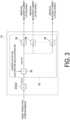
- FIG. 3 is a block diagram illustrating a configuration of a control device according to an embodiment.
- control of the hydrogen production facility 100 including N electrolysis cells 2 and N rectifiers 8 will be described.
- the control device 10 is configured to control the plurality of (that is, N) rectifiers 8 on the basis of measurement results obtained by the current sensors 14 and/or the flow rate sensor 16, and the like.
- the control device 10 includes a degradation coefficient acquisition unit 28 and an individual necessary current calculation unit 30. Further, as illustrated in FIG. 2 , the control device 10 may include a total necessary current acquisition unit 22, a first correlation acquisition unit 24, a second correlation acquisition unit 26, a control unit 31, and/or a storage unit 32.
- the control device 10 includes a computer including a processor (central processing unit (CPU) or the like), a primary storage device (memory device; random access memory (RAM) or the like), an auxiliary storage device, an interface, and the like.
- the control device 10 is configured to receive signals from the current sensors 14 and/or the flow rate sensor 16 via the interface.
- the processor is configured to process the signals received in this manner. Further, the processor is configured to process programs loaded in the primary storage device. Accordingly, functions of the total necessary current acquisition unit 22, the first correlation acquisition unit 24, the second correlation acquisition unit 26, the degradation coefficient acquisition unit 28, the individual necessary current calculation unit 30, and the control unit 31 described above are realized.
- the storage unit 32 described above may include the primary storage device or the auxiliary storage device of the computer constituting the control device 10.
- the processing contents of the control device 10 are implemented as programs to be executed by the processor.
- the programs may be stored in, for example, the auxiliary storage device.
- the programs are loaded in the primary storage device.
- the processor is configured to read the programs from the primary storage device and execute instructions included in the programs.
- the total necessary current acquisition unit 22 is configured to acquire a total necessary current I total corresponding to a hydrogen generation volume required for the hydrogen production facility 100.
- the total necessary current acquisition unit 22 may include a converter 23 (refer to FIG. 3 ) that converts the hydrogen generation volume required for the hydrogen production facility 100 into the total necessary current I total .
- the converter 23 may be configured to convert the hydrogen generation volume into the total necessary current I total by using a function indicating a correlation between the hydrogen generation volume and the total necessary current I total .
- the total necessary current acquisition unit 22 may acquire the consumption flow rate of hydrogen in the hydrogen consumption facility 6 supplied with hydrogen from the storage part 4, and calculate the total necessary current I total of the hydrogen production facility 100 on the basis of the consumption flow rate.
- the total necessary current acquisition unit 22 may acquire a flow rate of hydrogen supplied from the storage part 4 to the hydrogen consumption facility 6 as the consumption flow rate of hydrogen in the hydrogen consumption facility 6.
- the hydrogen flow rate measured by the flow rate sensor 16 (refer to FIG. 1 ) may be acquired as the consumption flow rate.
- the total necessary current acquisition unit 22 may calculate the consumption flow rate of hydrogen on the basis of a fuel command value that is a command value of the fuel flow rate supplied to the hydrogen consumption facility 6 as the consumption flow rate of hydrogen in the hydrogen consumption facility 6.
- the total necessary current acquisition unit 22 may be configured to convert the fuel command value into a hydrogen flow rate using a function that indicates a correlation between the fuel command value and the hydrogen flow rate.
- the first correlation acquisition unit 24 is configured to acquire, for each of the plurality of (N) electrolysis cells 2, a first correlation indicating a correlation between an applied voltage to the electrolysis cell 2 and a current flowing through a circuit including the electrolysis cell 2 at a beginning of life (BOL) of the electrolysis cell 2.
- the first correlation is determined by specifications (design) of the electrolysis cell 2, and can be acquired in advance.
- the first correlation thus acquired in advance may be stored in the storage unit 32 in advance.
- the first correlation acquisition unit 24 may be configured to acquire the first correlation stored in advance in the storage unit 32.
- the first correlation acquisition unit 24 may calculate an approximate curve (approximate straight line or the like) from the two or more data points and acquire the approximate curve thus calculated as the first correlation.
- the measurement value of the current described above may be a value acquired using the current sensor 14 (refer to FIG. 1 ).
- the measurement value of the applied voltage described above may be a measurement value of a voltage sensor (not illustrated) that measures the voltage between the pair of electrodes of the electrolysis cell 2.
- the second correlation acquisition unit 26 is configured to acquire, for each of the plurality of (N) electrolysis cells 2, a second correlation indicating a correlation between the voltage applied to the electrolysis cell 2 and the current flowing through the circuit including the electrolysis cell 2 at an end of life (EOL) of the electrolysis cell 2.
- the second correlation is determined by the specifications (design) of the electrolysis cell 2, and can be acquired in advance.
- the second correlation thus acquired in advance may be stored in the storage unit 32 in advance.
- the second correlation acquisition unit 26 may be configured to acquire the second correlation stored in advance in the storage unit 32.
- two or more data points related to the applied voltage described above and the current described above at the end of life of the electrolysis cell 2 may be measured, and the second correlation may be calculated on the basis of the two or more data points.
- the second correlation acquisition unit 26 may calculate an approximate curve (approximate straight line or the like) from the two or more data points and acquire the approximate curve thus calculated as the second correlation.
- the measurement value of the current described above may be a value acquired using the current sensor 14 (refer to FIG. 1 ).
- the measurement value of the applied voltage described above may be a measurement value of a voltage sensor (not illustrated) that measures the voltage between the pair of electrodes of the electrolysis cell 2.
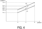
- FIG. 4 is a graph for describing procedures of a method of control according to an embodiment.
- a vertical axis of the graph of FIG. 4 represents an applied voltage V of the electrolysis cell 2 (that is, output voltage of the rectifier 8), and a horizontal axis represents current I of the circuit including the electrolysis cell 2.
- a current value necessary to obtain a hydrogen generation volume Fa (for example, 40% during rated operation) is Ia
- a current value necessary to obtain a hydrogen generation volume Fb (for example, 100% during rated operation) is Ib.
- the applied voltage (design value) for obtaining the current value Ia at the beginning of life is V BOL_a
- the applied voltage (design value) for obtaining the current value Ib at the beginning of life is V BOL_b .
- V BOL (V BOL_b - V BOL_a )/(Ib - Ia) ⁇ I + ⁇ BOL (where ⁇ BOL is an intercept).
- a straight line L1 is a straight line indicating this first correlation.
- the applied voltage (design value) for obtaining the current value Ia at the end of life is V EOL_a
- the applied voltage (design value) for obtaining the current value Ib at the end of life is V EOL_b .
- V EOL (V EOL_b - V EOL_a )/(Ib - Ia) ⁇ I + ⁇ EOL (where ⁇ EOL is an intercept).
- a straight line L2 is a straight line indicating this second correlation.
- the degradation coefficient acquisition unit 28 is configured to acquire a plurality of (that is, N) degradation coefficients D i (D 1 , D 2 , ..., D N ) respectively indicating degrees of deterioration of the N electrolysis cells 2 on the basis of the first correlation acquired by the first correlation acquisition unit 24 and the second correlation acquired by the second correlation acquisition unit 26.
- the degradation coefficient acquisition unit 28 may be configured to calculate, for each of the plurality of electrolysis cells 2, the degradation coefficient Di on the basis of an applied voltage to the electrolysis cell 2 necessary at present to cause a current of a specific value to flow through a circuit including the electrolysis cell, a voltage value corresponding to the current of the specific value determined from the first correlation described above, and a voltage value corresponding to the current of the specific value determined from the second correlation.
- the degradation coefficient D i can be calculated as a deterioration rate at the beginning of life of the electrolysis cell 2 (100% at the beginning of life, 0% at the end of life).
- the degradation coefficient D i (D 1 , D 2 , ..., D N ) can be calculated, for example, as follows.
- the measurement value (operation data or the like) of the applied voltage necessary at present to cause a current Ic of the specific value to flow through the circuit including the electrolysis cell 2 is defined as Vcur_c (indicated by point P in FIG. 4 ).
- an applied voltage V BOL_c necessary at the beginning of life of the electrolysis cell 2 for causing the current Ic described above to flow can be calculated from the first correlation described above
- an applied voltage V EOL_c necessary at the end of life of the electrolysis cell 2 for causing the Ic described above to flow can be calculated from the second correlation described above (refer to FIG. 4 ).
- the degradation coefficient (deterioration rate) D i at present (100% at the beginning of life and 0% at the end of life) for the target electrolysis cell 2 can be expressed by, for example, Equation (A) below.
- D i V EOL _ c ⁇ Vcur _ c / V EOL_c ⁇ V BOL_c ⁇ 100 %
- the plurality of degradation coefficients D i (D 1 , D 2 , ..., D N ) can be calculated using, for example, Equation (A) described above.
- the individual necessary current calculation unit 30 is configured to calculate a plurality of individual necessary currents I i (I 1 , I 2 , ..., I N ) respectively indicating necessary currents required for the plurality of electrolysis cells 2 on the basis of the total necessary current I total acquired by the total necessary current acquisition unit 22 and the plurality of degradation coefficients D i (D 1 , D 2 , ..., D N ) acquired by the degradation coefficient acquisition unit 28.
- the individual necessary current calculation unit 30 may calculate the plurality of individual necessary currents I i (I 1 , I 2 , ..., I N ) corresponding to the plurality of electrolysis cells 2 using respective ratios (D i /D AVG ) of the degradation coefficients D i of the plurality of electrolysis cells to an average D AVG of the degradation coefficients D i (D 1 , D 2 , ..., D N ) of the plurality of electrolysis cells 2.
- the average D AVG of the plurality of degradation coefficients D i may be an arithmetic average of the plurality of degradation coefficients D i .
- the average D AVG of the plurality of degradation coefficients is expressed by Equation (B) below.
- D AVG D 1 + D 2 + ... + D N / N
- the plurality of individual necessary currents I i (I 1 , I 2 , ..., I N ) can be calculated, for example, as follows.
- the individual necessary current calculation unit 30 divides the total necessary current I total acquired by the total necessary current acquisition unit 22 by the number N of the electrolysis cells 2 in operation to obtain a temporary necessary current I total /N per electrolysis cell 2.
- the individual necessary current calculation unit 30 may include a divider 36 configured to divide the total necessary current I total by the number N of the electrolysis cells 2 in operation.
- the individual necessary current I i I total / N ⁇ D i / D AVG
- the individual necessary current calculation unit 30 may include a converter 38 configured to convert the necessary current I total /N into the individual necessary current I i by multiplying the temporary necessary current I total /N described above by the ratio (D i /D AVG ) described above.
- the plurality of individual necessary currents I i (I 1 , I 2 , ..., I N ) can be calculated using the Equation (C) described above.
- the control unit 31 is configured to respectively control the plurality of (that is, N) rectifiers 8 on the basis of the plurality of individual necessary currents I i (I 1 , I 2 , ..., I N ) calculated by the individual necessary current calculation unit 30.
- the control unit 31 may be configured to adjust the output voltage of each rectifier 8 so that the currents flowing through the circuits including the respective electrolysis cells 2 corresponding to each rectifier 8 match or approach the individual necessary currents I i (I 1 , I 2 , ..., I N ).
- the storage unit 32 may store measurement values or design values acquired in advance or the first correlation and/or the second correlation described above, or the like.
- the degree of deterioration of the electrolysis cell 2 is reflected in the cell voltage during operation, and a higher applied voltage to the electrolysis cell (that is, output voltage from the rectifier to the electrolysis cell) with respect to the same hydrogen generation volume (that is, with respect to the same current) indicates more advanced deterioration of the electrolysis cell.
- the degradation coefficient D i can be appropriately acquired on the basis of the first correlation indicating the correlation between the applied voltage to the electrolysis cell 2 and the current flowing through the circuit including the electrolysis cell 2 at the beginning of life of the electrolysis cell 2, and the second correlation indicating the correlation at the end of life of the electrolysis cell 2.
- the individual necessary currents respectively required for the plurality of electrolysis cells are calculated on the basis of the degradation coefficients D i for the plurality of electrolysis cells 2 thus acquired and the total necessary current I total corresponding to the hydrogen generation volume required for the hydrogen production facility 100 as a whole, making it possible to appropriately distribute the necessary currents in accordance with the respective degrees of deterioration of the plurality of electrolysis cells 2. For example, for the electrolysis cells 2 relatively advanced in deterioration, the necessary currents can be distributed so that the individual necessary currents I i are relatively small.
- DC voltage is output from the rectifiers 8 to each electrolysis cell 2 on the basis of the plurality of individual necessary currents I i thus calculated, making it possible to delay the deterioration of the electrolysis cells 2 relatively advanced in deterioration, for example, and reduce the variations in the degree of deterioration among the plurality of electrolysis cells 2. Therefore, according to the embodiment described above, it is possible to lengthen the operation period (service life) of the hydrogen production facility 100 as a whole.
- the degradation coefficient described above can be acquired on the basis of the applied voltage to the electrolysis cell 2 necessary at present to cause a current of a specific value to flow through the circuit including the electrolysis cell 2, the voltage value corresponding to the current of the specific value determined from the first correlation described above, and the voltage value corresponding to the current of the specific value determined from the second correlation described above. This makes it possible to acquire appropriate degradation coefficients D i for the plurality of electrolysis cells 2 by a simple means.
- the plurality of individual necessary currents I i corresponding to the plurality of electrolysis cells 2 are respectively calculated using the respective ratios of the degradation coefficients D i of the plurality of electrolysis cells 2 to the average D AVE of the degradation coefficients of the plurality of electrolysis cells 2. This makes it possible to appropriately distribute the necessary currents in accordance with the respective degrees of deterioration of the plurality of electrolysis cells 2. For example, for the electrolysis cells 2 relatively advanced in deterioration, the necessary currents can be distributed so that the individual necessary currents I i are relatively small.
- the plurality of rectifiers 8 are controlled on the basis of the individual necessary currents I I thus calculated, making it easier to reduce the variations in the degree of deterioration among the plurality of electrolysis cells 2. This makes it possible to lengthen the operating period of the hydrogen production facility 100 as a whole.
- the degree of deterioration of the electrolysis cell is reflected in the cell voltage during operation, and a higher applied voltage to the electrolysis cell (that is, output voltage from the rectifier to the electrolysis cell) with respect to the same hydrogen generation volume (that is, with respect to the same current) indicates further progress in deterioration of the electrolysis cell.
- the degradation coefficient can be appropriately acquired on the basis of the first correlation indicating the correlation between the applied voltage to the electrolysis cell and the current flowing through the circuit including the electrolysis cell at the beginning of life of the electrolysis cell, and the second correlation indicating the correlation at the end of life of the electrolysis cell.
- the individual necessary currents respectively required for the plurality of electrolysis cells are calculated on the basis of the degradation coefficients for the plurality of electrolysis cells thus acquired and the total necessary current corresponding to the hydrogen generation volume required for the hydrogen production facility as a whole, making it possible to appropriately distribute the necessary currents in accordance with the respective degrees of deterioration of the plurality of electrolysis cells. For example, for the electrolysis cells relatively advanced in deterioration, the necessary currents can be distributed so that the individual necessary currents are relatively small.
- DC voltage is output from the rectifiers to each electrolysis cell on the basis of the plurality of individual necessary currents thus calculated, making it possible to delay the deterioration of the electrolysis cells relatively advanced in deterioration, for example, and reduce the variations in the degree of deterioration among the plurality of electrolysis cells. Therefore, according to the configuration of (1) described above, it is possible to lengthen the operation period (service life) of the hydrogen production facility as a whole.
- the degradation coefficient acquisition unit is configured to acquire, for each of the plurality of electrolysis cells, the degradation coefficient on the basis of an applied voltage (Vcur_c) to the electrolysis cell necessary at present to cause a current (I c ) of a specific value to flow through a circuit including the electrolysis cell, a voltage value (V BOL_c ) corresponding to the current of the specific value determined from the first correlation, and a voltage value (V EOL_c ) corresponding to the current of the specific value determined from the second correlation.
- Vcur_c applied voltage
- the degradation coefficient described above is acquired on the basis of the applied voltage to the electrolysis cell necessary at present to cause a current of a specific value to flow through the circuit including the electrolysis cell, the voltage value corresponding to the current of the specific value determined from the first correlation described above, and the voltage value corresponding to the current of the specific value determined from the second correlation described above.
- the control device includes a first correlation acquisition unit (24) configured to calculate, for each of the plurality of electrolysis cells using at least two pieces of data of an applied voltage to the electrolysis cell and a current flowing through a circuit including the electrolysis cell at a beginning of life of the electrolysis cell, an approximate curve indicating a relationship between the applied voltage and the current at the beginning of life (BOL) of the electrolysis cell as the first correlation.
- a first correlation acquisition unit (24) configured to calculate, for each of the plurality of electrolysis cells using at least two pieces of data of an applied voltage to the electrolysis cell and a current flowing through a circuit including the electrolysis cell at a beginning of life of the electrolysis cell, an approximate curve indicating a relationship between the applied voltage and the current at the beginning of life (BOL) of the electrolysis cell as the first correlation.
- an approximate curve (first correlation) indicating the relationship between the applied voltage and the current at the beginning of life of the electrolysis cell is calculated from at least two data points of the applied voltage to the electrolysis cell and the current flowing through the circuit including the electrolysis cell at the beginning of life of the electrolysis cell.
- the control device includes a second correlation acquisition unit (26) configured to calculate, for each of the plurality of electrolysis cells using at least two pieces of data of an applied voltage to the electrolysis cell and a current flowing through a circuit including the electrolysis cell at an end of life of the electrolysis cell, an approximate curve indicating a relationship between the applied voltage and the current at the end of life (EOL) of the electrolysis cell as the second correlation.
- a second correlation acquisition unit (26) configured to calculate, for each of the plurality of electrolysis cells using at least two pieces of data of an applied voltage to the electrolysis cell and a current flowing through a circuit including the electrolysis cell at an end of life of the electrolysis cell, an approximate curve indicating a relationship between the applied voltage and the current at the end of life (EOL) of the electrolysis cell as the second correlation.
- an approximate curve (second correlation) indicating the relationship between the applied voltage and the current at the end of life of the electrolysis cell is calculated from at least two data points of the applied voltage to the electrolysis cell and the current flowing through the circuit including the electrolysis cell at the end of life of the electrolysis cell.
- the individual necessary current calculation unit is configured to calculate the plurality of individual necessary currents corresponding to the plurality of electrolysis cells using a ratio (D i /D AVE ) of a degradation coefficient (D i ) of each of the plurality of electrolysis cells to an average (D AVE ) of the degradation coefficients of the plurality of electrolysis cells.
- the plurality of individual necessary currents corresponding to the plurality of electrolysis cells are respectively calculated using the respective ratios of the degradation coefficients of the plurality of electrolysis cells to the average of the degradation coefficients of the plurality of electrolysis cells. This makes it possible to appropriately distribute the necessary currents in accordance with the respective degrees of deterioration of the plurality of electrolysis cells. For example, for the electrolysis cell relatively advanced in deterioration, the necessary currents can be distributed so that the individual necessary currents are relatively small.
- the plurality of rectifiers are controlled on the basis of the individual necessary currents thus calculated, making it easier to reduce the variations in the degree of deterioration among the plurality of electrolysis cells. Therefore, according to the configuration of (5) described above, it is possible to lengthen the operation period of the hydrogen production facility as a whole.
- a hydrogen production facility (100) includes:
- the degradation coefficient can be appropriately acquired on the basis of the first correlation indicating the correlation between the applied voltage to the electrolysis cell and the current flowing through the circuit including the electrolysis cell at the beginning of life of the electrolysis cell, and the second correlation indicating the correlation at the end of life of the electrolysis cell.
- the individual necessary currents respectively required for the plurality of electrolysis cells are calculated on the basis of the degradation coefficients for the plurality of electrolysis cells thus acquired and the total necessary current corresponding to the hydrogen generation volume required for the hydrogen production facility as a whole, making it possible to appropriately distribute the necessary currents in accordance with the respective degrees of deterioration of the plurality of electrolysis cells. For example, for the electrolysis cell relatively advanced in deterioration, the necessary currents can be distributed so that the individual necessary currents are relatively small.
- DC voltage is output from the rectifiers to each electrolysis cell on the basis of the plurality of individual necessary currents thus calculated, making it possible to delay the deterioration of the electrolysis cells relatively advanced in deterioration, for example, and reduce the variations in the degree of deterioration among the plurality of electrolysis cells. Therefore, according to the configuration of (6) described above, it is possible to lengthen the operation period (service life) of the hydrogen production facility as a whole.
- a control method for a hydrogen production facility is a method for controlling a hydrogen production facility (100) including a plurality of electrolysis cells (2) for electrolyzing water or steam, and a plurality of rectifiers (8) for respectively supplying DC power to the plurality of electrolysis cells.
- the control method includes acquiring a plurality of degradation coefficients respectively indicating degrees of deterioration of the plurality of electrolysis cells, calculating, on the basis of a total necessary current corresponding to a hydrogen generation volume required for the hydrogen production facility and the plurality of degradation coefficients, a plurality of individual necessary currents respectively indicating necessary currents required for the plurality of electrolysis cells, and respectively controlling the plurality of rectifiers on the basis of the plurality of individual necessary currents.
- the acquiring the plurality of degradation coefficients acquires, for each of the plurality of electrolysis cells, the degradation coefficient on the basis of a first correlation indicating a correlation between an applied voltage to an electrolysis cell among the plurality of electrolysis cells and a current flowing through a circuit including the electrolysis cell at a beginning of life of the electrolysis cell and a second correlation indicating the correlation at an end of life of the electrolysis cell.
- the degradation coefficient can be appropriately acquired on the basis of the first correlation indicating the correlation between the applied voltage to the electrolysis cell and the current flowing through the circuit including the electrolysis cell at the beginning of life of the electrolysis cell, and the second correlation indicating the correlation at the end of life of the electrolysis cell.
- the individual necessary currents respectively required for the plurality of electrolysis cells are calculated on the basis of the degradation coefficients for the plurality of electrolysis cells thus acquired and the total necessary current corresponding to the hydrogen generation volume required for the hydrogen production facility as a whole, making it possible to appropriately distribute the necessary currents in accordance with the respective degrees of deterioration of the plurality of electrolysis cells. For example, for the electrolysis cell relatively advanced in deterioration, the necessary currents can be distributed so that the individual necessary currents are relatively small.
- DC voltage is output from the rectifiers to each electrolysis cell on the basis of the plurality of individual necessary currents thus calculated, making it possible to delay the deterioration of the electrolysis cells relatively advanced in deterioration, for example, and reduce the variations in the degree of deterioration among the plurality of electrolysis cells. Therefore, according to the method of (7) described above, it is possible to lengthen the operation period (service life) of the hydrogen production facility as a whole.
- a control program for a hydrogen production facility is a control program for controlling a hydrogen production facility (100) including a plurality of electrolysis cells (2) for electrolyzing water or steam, and a plurality of rectifiers (8) for supplying DC power to each of the plurality of electrolysis cells.
- the control program configured to cause a computer to execute acquiring a plurality of degradation coefficients respectively indicating degrees of deterioration of the plurality of electrolysis cells, calculating, on the basis of a total necessary current corresponding to a hydrogen generation volume required for the hydrogen production facility and the plurality of degradation coefficients, a plurality of individual necessary currents respectively indicating necessary currents required for the plurality of electrolysis cells, and respectively controlling the plurality of rectifiers on the basis of the plurality of individual necessary currents.
- the acquiring the plurality of degradation coefficients acquires, for each of the plurality of electrolysis cells, the degradation coefficient on the basis of a first correlation indicating a correlation between an applied voltage to an electrolysis cell among the plurality of electrolysis cells and a current flowing through a circuit including the electrolysis cell at a beginning of life of the electrolysis cell and a second correlation indicating the correlation at an end of life of the electrolysis cell.
- the degradation coefficient can be appropriately acquired on the basis of the first correlation indicating the correlation between the applied voltage to the electrolysis cell and the current flowing through the circuit including the electrolysis cell at the beginning of life of the electrolysis cell, and the second correlation indicating the correlation at the end of life of the electrolysis cell.
- the individual necessary currents respectively required for the plurality of electrolysis cells are calculated on the basis of the degradation coefficients for the plurality of electrolysis cells thus acquired and the total necessary current corresponding to the hydrogen generation volume required for the hydrogen production facility as a whole, making it possible to appropriately distribute the necessary currents in accordance with the respective degrees of deterioration of the plurality of electrolysis cells. For example, for the electrolysis cell relatively advanced in deterioration, the necessary currents can be distributed so that the individual necessary currents are relatively small.
- DC voltage is output from the rectifiers to each electrolysis cell on the basis of the plurality of individual necessary currents thus calculated, making it possible to delay the deterioration of the electrolysis cells relatively advanced in deterioration, for example, and reduce the variations in the degree of deterioration among the plurality of electrolysis cells. Therefore, according to the program of (8) described above, it is possible to lengthen the operation period (service life) of the hydrogen production facility as a whole.
- the present invention is not limited to the above-described embodiments, and includes forms obtained by modifying the above-described embodiments and forms obtained by appropriately combining these forms.
- an expression of a relative or absolute arrangement such as “in a direction”, “along a direction”, “parallel”, “orthogonal”, “centered”, “concentric”, or “coaxial” shall not be construed as indicating the arrangement only in a strict literal sense, but also construed as expressing a state where the arrangement is relatively displaced by a tolerance, or by an angle or a distance to the extent that the same function can be achieved.
- an expression of a state where features are equal such as “same”, “equal”, and “uniform” shall not be construed as indicating only a state where the features are equal in a strict literal sense, but also construed as expressing a state where there is a tolerance or a difference to the extent that the same function can be achieved.
- an expression indicating a shape such as a rectangular shape or a cylindrical shape shall not be construed as indicating only a shape such as a rectangular shape or a cylindrical shape in a strict geometrical sense, but also construed as indicating a shape including a depression, a protrusion, a chamfered portion, or the like to the extent that the same effect can be achieved.
Landscapes
- Chemical & Material Sciences (AREA)
- Engineering & Computer Science (AREA)
- Chemical Kinetics & Catalysis (AREA)
- Electrochemistry (AREA)
- Materials Engineering (AREA)
- Metallurgy (AREA)
- Organic Chemistry (AREA)
- Inorganic Chemistry (AREA)
- Analytical Chemistry (AREA)
- Automation & Control Theory (AREA)
- Electrolytic Production Of Non-Metals, Compounds, Apparatuses Therefor (AREA)
Abstract
Description
- The present disclosure relates to a control device for a hydrogen production facility, a hydrogen production facility, a method for controlling a hydrogen production facility, and a control program for a hydrogen production facility.
- The present application claims priority based on
JP 2022-126962 filed in the Japan Patent Office on August 9, 2022 - As a facility for producing hydrogen, a hydrogen production facility including an electrolytic device that generates hydrogen by electrolyzing water or steam is known.
- Patent Document 1 discloses a system for producing hydrogen by electrolyzing water in a water electrolysis device provided with an electrolysis cell including a solid electrolyte membrane.
- Patent Document 1:
JP 2002-129372 A - An electrolysis cell (electrolytic device) for electrolyzing water or steam deteriorates and decreases in performance over time or in accordance with an operation state (operating ratio or the like). Further, even when a plurality of electrolysis cells are operated under the same conditions, individual differences exist in a degree of deterioration.
- In a hydrogen production facility including a plurality of electrolysis cells having different degrees of deterioration, when the plurality of electrolysis cells are operated at an equal load (hydrogen generation volume), an electrolysis cell with advanced deterioration deteriorates more rapidly, resulting in the possibility that an operation period (service life) of the hydrogen production facility (plant) as a whole will be shortened.
- In view of the above circumstances, it is an object of at least one embodiment of the present invention to provide a control device for a hydrogen production facility, a hydrogen production facility, a method for controlling a hydrogen production facility, and a control program for a hydrogen production facility, which can lengthen an operation period of a plant as a whole.
- A control device for a hydrogen production facility according to at least one embodiment of the present invention is a control device for a hydrogen production facility including a plurality of electrolysis cells for electrolyzing water or steam, and a plurality of rectifiers for respectively supplying DC power to the plurality of electrolysis cells. The control device includes a degradation coefficient acquisition unit configured to acquire a plurality of degradation coefficients respectively indicating degrees of deterioration of the plurality of electrolysis cells, an individual necessary current calculation unit configured to calculate, on the basis of a total necessary current corresponding to a hydrogen generation volume required for the hydrogen production facility and the plurality of degradation coefficients, a plurality of individual necessary currents respectively indicating necessary currents required for the plurality of electrolysis cells, and a control unit configured to respectively control the plurality of rectifiers on the basis of the plurality of individual necessary currents. The degradation coefficient acquisition unit is configured to acquire, for each of the plurality of electrolysis cells, the degradation coefficient on the basis of a first correlation indicating a correlation between an applied voltage to an electrolysis cell among the plurality of electrolysis cells and a current flowing through a circuit including the electrolysis cell at a beginning of life of the electrolysis cell and a second correlation indicating the correlation at an end of life of the electrolysis cell.
- Further, a hydrogen production facility according to at least one embodiment of the present invention includes a plurality of electrolysis cells for electrolyzing water or steam, a plurality of rectifiers for respectively supplying DC power to the plurality of electrolysis cells, and the control device described above configured to adjust an output voltage or an output current of each of the plurality of rectifiers.
- Further, a control method for a hydrogen production facility according to at least one embodiment of the present invention is a control method for controlling a hydrogen production facility including a plurality of electrolysis cells for electrolyzing water or steam, and a plurality of rectifiers for respectively supplying DC power to the plurality of electrolysis cells. The control method includes acquiring a plurality of degradation coefficients respectively indicating degrees of deterioration of the plurality of electrolysis cells, calculating, on the basis of a total necessary current corresponding to a hydrogen generation volume required for the hydrogen production facility and the plurality of degradation coefficients, a plurality of individual necessary currents respectively indicating necessary currents required for the plurality of electrolysis cells, and respectively controlling the plurality of rectifiers on the basis of the plurality of individual necessary currents. The acquiring the plurality of degradation coefficients acquires, for each of the plurality of electrolysis cells, the degradation coefficient on the basis of a first correlation indicating a correlation between an applied voltage to an electrolysis cell among the plurality of electrolysis cells and a current flowing through a circuit including the electrolysis cell at a beginning of life of the electrolysis cell and a second correlation indicating the correlation at an end of life of the electrolysis cell.
- Further, a control program for a hydrogen production facility according to at least one embodiment of the present invention is a control program for controlling a hydrogen production facility including a plurality of electrolysis cells for electrolyzing water or steam, and a plurality of rectifiers for respectively supplying DC power to the plurality of electrolysis cells. The control program is configured to cause a computer to execute acquiring a plurality of degradation coefficients respectively indicating degrees of deterioration of the plurality of electrolysis cells, calculating, on the basis of a total necessary current corresponding to a hydrogen generation volume required for the hydrogen production facility and the plurality of degradation coefficients, a plurality of individual necessary currents respectively indicating necessary currents required for the plurality of electrolysis cells, and respectively controlling the plurality of rectifiers on the basis of the plurality of individual necessary currents. The acquiring the plurality of degradation coefficients acquires, for each of the plurality of electrolysis cells, the degradation coefficient on the basis of a first correlation indicating a correlation between an applied voltage to an electrolysis cell among the plurality of electrolysis cells and a current flowing through a circuit including the electrolysis cell at a beginning of life of the electrolysis cell and a second correlation indicating the correlation at an end of life of the electrolysis cell.
- According to at least one embodiment of the present invention, provided are a control device for a hydrogen production facility, a hydrogen production facility, a method for controlling a hydrogen production facility, and a control program for a hydrogen production facility, which can appropriately lengthen an operation period of a plant as a whole.
-
-
FIG. 1 is a schematic diagram of a hydrogen production facility to which a control device according to an embodiment is applied. -
FIG. 2 is a schematic configuration diagram of a control device according to an embodiment. -
FIG. 3 is a block diagram illustrating a configuration of a control device according to an embodiment. -
FIG. 4 is a graph for describing procedures of a method of control according to an embodiment. - Embodiments of the present invention will be described in detail below with reference to the accompanying drawings. However, the dimensions, materials, shapes, relative arrangements, or the like of the components described as embodiments or illustrated in the drawings are not intended to limit the scope of the present invention but are merely illustrative examples.
-
FIG. 1 is a schematic diagram of a hydrogen production facility to which a control device according to an embodiment is applied. As illustrated inFIG. 1 , ahydrogen production facility 100 includes a plurality of electrolysis cells 2 (2A, 2B), a plurality of rectifiers 8 (8A, 8B), and acontrol device 10. Thehydrogen production facility 100 may include astorage part 4 that stores hydrogen generated at the plurality of electrolysis cells 2(2A, 2B). Note that, although twoelectrolysis cells 2 and tworectifiers 8 are illustrated inFIG. 1 , quantities of theelectrolysis cells 2 and therectifiers 8 constituting thehydrogen production facility 100 are not limited. - Each of the plurality of electrolysis cells 2 (2A, 2B) is configured to electrolyze water or steam by DC voltage being applied thereto. A type of the plurality of
electrolysis cells 2 is not limited. The plurality ofelectrolysis cells 2 may be, for example, electrolysis cells (electrolytic tanks) for an alkaline water electrolysis device, a polymer electrolyte membrane (PEM) water electrolysis device, or an anion exchange membrane (AEM) water electrolysis device for electrolyzing water (liquid), or may be electrolysis cells of a solid oxide electrolysis cell (SOEC) electrolytic device for electrolyzing steam. - The plurality of rectifiers 8 (8A, 8B) are configured to respectively supply DC power to the plurality of electrolysis cells 2 (2A, 2B). Each of the plurality of
rectifiers 8 is supplied with power (typically AC power) from apower source 90 via atransmission system 92. Thepower source 90 may be a power grid or other power source (power generation device or energy storage device (battery), for example). The plurality ofrectifiers 8 each convert the power from thepower source 90 from AC power to DC power as necessary and respectively output the DC power to the plurality ofelectrolysis cells 2 as DC voltage. Hereinafter, the DC voltage output from therectifiers 8 to the electrolysis cells 2 (voltage applied to the electrolysis cells 2) is also referred to as output voltage. Further, therectifiers 8 are configured to be capable of changing the output voltage. - Water or steam is supplied to the
electrolysis cells 2. As described above, DC power is supplied to theelectrolysis cells 2 via therectifiers 8. The water or the steam in theelectrolysis cell 2 is electrolyzed by DC applying voltage between a pair of electrodes provided in theelectrolysis cell 2 via therectifier 8 to produce hydrogen on a cathode side and oxygen on an anode side. Water (electrolyte solution) in which an electrolyte is dissolved may be supplied to theelectrolysis cell 2 and the water (water constituting the electrolyte solution) may be electrolyzed. The electrolyte may be an alkaline substance such as potassium hydroxide (KOH). - The hydrogen gas produced on the cathode side of the
electrolysis cell 2 is guided to a gas-liquid separator and/or a dehumidifier to remove moisture, and then guided to thestorage part 4. The oxygen gas produced on the anode side of theelectrolysis cell 2 is guided to a gas-liquid separator and/or a dehumidifier to remove moisture, and then may be supplied to an oxygen consumption facility, or may be discharged to the outside. - The
storage part 4 is configured to store gaseous hydrogen. The hydrogen stored in thestorage part 4 may be supplied to ahydrogen consumption facility 6. Thestorage part 4 may have characteristics suitable for supplying hydrogen to thehydrogen consumption facility 6. Thestorage part 4 may include, for example, a storage header (header tank). - The
hydrogen consumption facility 6 may include, for example, hydrogen combustion facilities configured to burn hydrogen (gas turbine facilities or iron production facilities, for example), hydrogen liquefaction facilities configured to liquefy hydrogen, facilities that generate electricity by chemical reaction using hydrogen as fuel (power generation facilities including fuel cells such as solid oxide fuel cells (SOFCs), for example), facilities that manufacture fuel using hydrogen as feedstock (fuel synthesis facilities, for example), or hydrogen gas stations configured to supply hydrogen to the equipment. - The
hydrogen production facility 100 may include a plurality of current sensors 14 (14A, 14B) for measuring the DC currents flowing through circuits respectively including the plurality ofelectrolysis cells 2 when water is electrolyzed in the plurality ofelectrolysis cells 2. The circuit includes electric wires respectively connecting a pair of output terminals of the DC voltage of therectifier 8 and the pair of electrodes of theelectrolysis cell 2. The current sensors 14 (14A, 14B) may be configured to measure a current flowing between one of the pair of terminals described above of therectifier 8 and one of the pair of electrodes of theelectrolysis cell 2. - The
hydrogen production facility 100 may include aflow rate sensor 16 for measuring a consumption flow rate of hydrogen at thehydrogen consumption facility 6. Theflow rate sensor 16 may be provided on a line for guiding hydrogen from thestorage part 4 to thehydrogen consumption facility 6, as illustrated inFIG. 1 . - The
current sensors 14 and/or theflow rate sensor 16 may be electrically connected to thecontrol device 10, and a signal indicating measurement results by thecurrent sensors 14 and/or theflow rate sensor 16 may be sent to thecontrol device 10. - Next, a control device and a method for controlling a hydrogen production facility according to some embodiments will be described.
FIG. 2 is a schematic configuration diagram of a control device according to an embodiment.FIG. 3 is a block diagram illustrating a configuration of a control device according to an embodiment. In the following description, control of thehydrogen production facility 100 includingN electrolysis cells 2 andN rectifiers 8 will be described. Thecontrol device 10 is configured to control the plurality of (that is, N)rectifiers 8 on the basis of measurement results obtained by thecurrent sensors 14 and/or theflow rate sensor 16, and the like. - As illustrated in
FIG. 2 andFIG. 3 , thecontrol device 10 according to an embodiment includes a degradationcoefficient acquisition unit 28 and an individual necessarycurrent calculation unit 30. Further, as illustrated inFIG. 2 , thecontrol device 10 may include a total necessarycurrent acquisition unit 22, a firstcorrelation acquisition unit 24, a secondcorrelation acquisition unit 26, acontrol unit 31, and/or astorage unit 32. - The
control device 10 includes a computer including a processor (central processing unit (CPU) or the like), a primary storage device (memory device; random access memory (RAM) or the like), an auxiliary storage device, an interface, and the like. Thecontrol device 10 is configured to receive signals from thecurrent sensors 14 and/or theflow rate sensor 16 via the interface. The processor is configured to process the signals received in this manner. Further, the processor is configured to process programs loaded in the primary storage device. Accordingly, functions of the total necessarycurrent acquisition unit 22, the firstcorrelation acquisition unit 24, the secondcorrelation acquisition unit 26, the degradationcoefficient acquisition unit 28, the individual necessarycurrent calculation unit 30, and thecontrol unit 31 described above are realized. Note that thestorage unit 32 described above may include the primary storage device or the auxiliary storage device of the computer constituting thecontrol device 10. - The processing contents of the
control device 10 are implemented as programs to be executed by the processor. The programs may be stored in, for example, the auxiliary storage device. When the programs are executed, the programs are loaded in the primary storage device. The processor is configured to read the programs from the primary storage device and execute instructions included in the programs. - The total necessary
current acquisition unit 22 is configured to acquire a total necessary current Itotal corresponding to a hydrogen generation volume required for thehydrogen production facility 100. The total necessarycurrent acquisition unit 22 may include a converter 23 (refer toFIG. 3 ) that converts the hydrogen generation volume required for thehydrogen production facility 100 into the total necessary current Itotal. Theconverter 23 may be configured to convert the hydrogen generation volume into the total necessary current Itotal by using a function indicating a correlation between the hydrogen generation volume and the total necessary current Itotal. - For example, the total necessary
current acquisition unit 22 may acquire the consumption flow rate of hydrogen in thehydrogen consumption facility 6 supplied with hydrogen from thestorage part 4, and calculate the total necessary current Itotal of thehydrogen production facility 100 on the basis of the consumption flow rate. The total necessarycurrent acquisition unit 22 may acquire a flow rate of hydrogen supplied from thestorage part 4 to thehydrogen consumption facility 6 as the consumption flow rate of hydrogen in thehydrogen consumption facility 6. In this case, the hydrogen flow rate measured by the flow rate sensor 16 (refer toFIG. 1 ) may be acquired as the consumption flow rate. Alternatively, the total necessarycurrent acquisition unit 22 may calculate the consumption flow rate of hydrogen on the basis of a fuel command value that is a command value of the fuel flow rate supplied to thehydrogen consumption facility 6 as the consumption flow rate of hydrogen in thehydrogen consumption facility 6. In this case, the total necessarycurrent acquisition unit 22 may be configured to convert the fuel command value into a hydrogen flow rate using a function that indicates a correlation between the fuel command value and the hydrogen flow rate. - The first
correlation acquisition unit 24 is configured to acquire, for each of the plurality of (N)electrolysis cells 2, a first correlation indicating a correlation between an applied voltage to theelectrolysis cell 2 and a current flowing through a circuit including theelectrolysis cell 2 at a beginning of life (BOL) of theelectrolysis cell 2. - The first correlation is determined by specifications (design) of the
electrolysis cell 2, and can be acquired in advance. The first correlation thus acquired in advance may be stored in thestorage unit 32 in advance. The firstcorrelation acquisition unit 24 may be configured to acquire the first correlation stored in advance in thestorage unit 32. - Alternatively, two or more data points related to the applied voltage described above and the current described above at the beginning of life of the
electrolysis cell 2 may be measured, and the first correlation may be calculated on the basis of the two or more data points. The firstcorrelation acquisition unit 24 may calculate an approximate curve (approximate straight line or the like) from the two or more data points and acquire the approximate curve thus calculated as the first correlation. The measurement value of the current described above may be a value acquired using the current sensor 14 (refer toFIG. 1 ). The measurement value of the applied voltage described above may be a measurement value of a voltage sensor (not illustrated) that measures the voltage between the pair of electrodes of theelectrolysis cell 2. - The second
correlation acquisition unit 26 is configured to acquire, for each of the plurality of (N)electrolysis cells 2, a second correlation indicating a correlation between the voltage applied to theelectrolysis cell 2 and the current flowing through the circuit including theelectrolysis cell 2 at an end of life (EOL) of theelectrolysis cell 2. - The second correlation is determined by the specifications (design) of the
electrolysis cell 2, and can be acquired in advance. The second correlation thus acquired in advance may be stored in thestorage unit 32 in advance. The secondcorrelation acquisition unit 26 may be configured to acquire the second correlation stored in advance in thestorage unit 32. - Alternatively, two or more data points related to the applied voltage described above and the current described above at the end of life of the
electrolysis cell 2 may be measured, and the second correlation may be calculated on the basis of the two or more data points. The secondcorrelation acquisition unit 26 may calculate an approximate curve (approximate straight line or the like) from the two or more data points and acquire the approximate curve thus calculated as the second correlation. The measurement value of the current described above may be a value acquired using the current sensor 14 (refer toFIG. 1 ). The measurement value of the applied voltage described above may be a measurement value of a voltage sensor (not illustrated) that measures the voltage between the pair of electrodes of theelectrolysis cell 2. - The first correlation coefficient and the second correlation coefficient can be calculated, for example, as follows. Here,
FIG. 4 is a graph for describing procedures of a method of control according to an embodiment. A vertical axis of the graph ofFIG. 4 represents an applied voltage V of the electrolysis cell 2 (that is, output voltage of the rectifier 8), and a horizontal axis represents current I of the circuit including theelectrolysis cell 2. - In a
certain electrolysis cell 2, a current value necessary to obtain a hydrogen generation volume Fa (for example, 40% during rated operation) is Ia, and a current value necessary to obtain a hydrogen generation volume Fb (for example, 100% during rated operation) is Ib. Further, in thiselectrolysis cell 2, the applied voltage (design value) for obtaining the current value Ia at the beginning of life is VBOL_a, and the applied voltage (design value) for obtaining the current value Ib at the beginning of life is VBOL_b. - From these two data points of the current and the applied voltage (that is, (Ia, VBOL_a) and (Ib, VBOL_b)), the correlation (first correlation) between the applied voltage VBOL and the current I at the beginning of life of this
electrolysis cell 2 can be expressed by VBOL = (VBOL_b - VBOL_a)/(Ib - Ia) × I + αBOL (where αBOL is an intercept). InFIG. 4 , a straight line L1 is a straight line indicating this first correlation. - Further, in the
electrolysis cell 2 described above, the applied voltage (design value) for obtaining the current value Ia at the end of life is VEOL_a, and the applied voltage (design value) for obtaining the current value Ib at the end of life is VEOL_b. - From these two data points of the current and the applied voltage (that is, (Ia, VEOL_a) and (Ib, VEOL_b)), the correlation (second correlation) between the applied voltage VEOL and the current I at the end of life of the
electrolysis cell 2 can be expressed by VEOL = (VEOL_b - VEOL_a)/(Ib - Ia) × I + αEOL (where αEOL is an intercept). InFIG. 4 , a straight line L2 is a straight line indicating this second correlation. - The degradation
coefficient acquisition unit 28 is configured to acquire a plurality of (that is, N) degradation coefficients Di (D1, D2, ..., DN) respectively indicating degrees of deterioration of theN electrolysis cells 2 on the basis of the first correlation acquired by the firstcorrelation acquisition unit 24 and the second correlation acquired by the secondcorrelation acquisition unit 26. - The degradation
coefficient acquisition unit 28 may be configured to calculate, for each of the plurality ofelectrolysis cells 2, the degradation coefficient Di on the basis of an applied voltage to theelectrolysis cell 2 necessary at present to cause a current of a specific value to flow through a circuit including the electrolysis cell, a voltage value corresponding to the current of the specific value determined from the first correlation described above, and a voltage value corresponding to the current of the specific value determined from the second correlation. - In an embodiment, the degradation coefficient Di can be calculated as a deterioration rate at the beginning of life of the electrolysis cell 2 (100% at the beginning of life, 0% at the end of life).
- More specifically, the degradation coefficient Di (D1, D2, ..., DN) can be calculated, for example, as follows. For the
electrolysis cell 2 for which the degradation coefficient Di is to be calculated, the measurement value (operation data or the like) of the applied voltage necessary at present to cause a current Ic of the specific value to flow through the circuit including theelectrolysis cell 2 is defined as Vcur_c (indicated by point P inFIG. 4 ). Further, an applied voltage VBOL_c necessary at the beginning of life of theelectrolysis cell 2 for causing the current Ic described above to flow can be calculated from the first correlation described above, and an applied voltage VEOL_c necessary at the end of life of theelectrolysis cell 2 for causing the Ic described above to flow can be calculated from the second correlation described above (refer toFIG. 4 ). - In this case, the degradation coefficient (deterioration rate) Di at present (100% at the beginning of life and 0% at the end of life) for the
target electrolysis cell 2 can be expressed by, for example, Equation (A) below.
- For the plurality of
electrolysis cells 2, the plurality of degradation coefficients Di (D1, D2, ..., DN) can be calculated using, for example, Equation (A) described above. - The individual necessary
current calculation unit 30 is configured to calculate a plurality of individual necessary currents Ii (I1, I2, ..., IN) respectively indicating necessary currents required for the plurality ofelectrolysis cells 2 on the basis of the total necessary current Itotal acquired by the total necessarycurrent acquisition unit 22 and the plurality of degradation coefficients Di (D1, D2, ..., DN) acquired by the degradationcoefficient acquisition unit 28. - The individual necessary
current calculation unit 30 may calculate the plurality of individual necessary currents Ii (I1, I2, ..., IN) corresponding to the plurality ofelectrolysis cells 2 using respective ratios (Di/DAVG) of the degradation coefficients Di of the plurality of electrolysis cells to an average DAVG of the degradation coefficients Di (D1, D2, ..., DN) of the plurality ofelectrolysis cells 2. Note that the average DAVG of the plurality of degradation coefficients Di may be an arithmetic average of the plurality of degradation coefficients Di. In this case, the average DAVG of the plurality of degradation coefficients is expressed by Equation (B) below.
- More specifically, the plurality of individual necessary currents Ii (I1, I2, ..., IN) can be calculated, for example, as follows. As illustrated in
FIG. 3 , the individual necessarycurrent calculation unit 30 divides the total necessary current Itotal acquired by the total necessarycurrent acquisition unit 22 by the number N of theelectrolysis cells 2 in operation to obtain a temporary necessary current Itotal/N perelectrolysis cell 2. Note that, as illustrated inFIG. 3 , the individual necessarycurrent calculation unit 30 may include adivider 36 configured to divide the total necessary current Itotal by the number N of theelectrolysis cells 2 in operation. - Next, for each of the
N electrolysis cells 2, the individual necessary current Ii (I1, I2, ..., IN) that is the necessary current required for theelectrolysis cell 2 may be calculated by multiplying the temporary necessary current Itotal/N described above by the ratio (Di/DAVG) described above. That is, the individual necessary currents Ii (I1, I2, ..., IN) for therespective electrolysis cells 2 may be calculated from Equation (C) below.
- Note that, as illustrated in
FIG. 3 , the individual necessarycurrent calculation unit 30 may include aconverter 38 configured to convert the necessary current Itotal/N into the individual necessary current Ii by multiplying the temporary necessary current Itotal/N described above by the ratio (Di/DAVG) described above. - For the plurality of
electrolysis cells 2, the plurality of individual necessary currents Ii (I1, I2, ..., IN) can be calculated using the Equation (C) described above. - The
control unit 31 is configured to respectively control the plurality of (that is, N)rectifiers 8 on the basis of the plurality of individual necessary currents Ii (I1, I2, ..., IN) calculated by the individual necessarycurrent calculation unit 30. Thecontrol unit 31 may be configured to adjust the output voltage of eachrectifier 8 so that the currents flowing through the circuits including therespective electrolysis cells 2 corresponding to eachrectifier 8 match or approach the individual necessary currents Ii (I1, I2, ..., IN). - The
storage unit 32 may store measurement values or design values acquired in advance or the first correlation and/or the second correlation described above, or the like. - The degree of deterioration of the
electrolysis cell 2 is reflected in the cell voltage during operation, and a higher applied voltage to the electrolysis cell (that is, output voltage from the rectifier to the electrolysis cell) with respect to the same hydrogen generation volume (that is, with respect to the same current) indicates more advanced deterioration of the electrolysis cell. In this regard, according to the embodiment described above, for each of the plurality ofelectrolysis cells 2, the degradation coefficient Di can be appropriately acquired on the basis of the first correlation indicating the correlation between the applied voltage to theelectrolysis cell 2 and the current flowing through the circuit including theelectrolysis cell 2 at the beginning of life of theelectrolysis cell 2, and the second correlation indicating the correlation at the end of life of theelectrolysis cell 2. - Further, the individual necessary currents respectively required for the plurality of electrolysis cells are calculated on the basis of the degradation coefficients Di for the plurality of
electrolysis cells 2 thus acquired and the total necessary current Itotal corresponding to the hydrogen generation volume required for thehydrogen production facility 100 as a whole, making it possible to appropriately distribute the necessary currents in accordance with the respective degrees of deterioration of the plurality ofelectrolysis cells 2. For example, for theelectrolysis cells 2 relatively advanced in deterioration, the necessary currents can be distributed so that the individual necessary currents Ii are relatively small. DC voltage is output from therectifiers 8 to eachelectrolysis cell 2 on the basis of the plurality of individual necessary currents Ii thus calculated, making it possible to delay the deterioration of theelectrolysis cells 2 relatively advanced in deterioration, for example, and reduce the variations in the degree of deterioration among the plurality ofelectrolysis cells 2. Therefore, according to the embodiment described above, it is possible to lengthen the operation period (service life) of thehydrogen production facility 100 as a whole. - Further, as described above, in some embodiments, for each of the plurality of
electrolysis cells 2, the degradation coefficient described above can be acquired on the basis of the applied voltage to theelectrolysis cell 2 necessary at present to cause a current of a specific value to flow through the circuit including theelectrolysis cell 2, the voltage value corresponding to the current of the specific value determined from the first correlation described above, and the voltage value corresponding to the current of the specific value determined from the second correlation described above. This makes it possible to acquire appropriate degradation coefficients Di for the plurality ofelectrolysis cells 2 by a simple means. - Further, as described above, in some embodiments, the plurality of individual necessary currents Ii corresponding to the plurality of
electrolysis cells 2 are respectively calculated using the respective ratios of the degradation coefficients Di of the plurality ofelectrolysis cells 2 to the average DAVE of the degradation coefficients of the plurality ofelectrolysis cells 2. This makes it possible to appropriately distribute the necessary currents in accordance with the respective degrees of deterioration of the plurality ofelectrolysis cells 2. For example, for theelectrolysis cells 2 relatively advanced in deterioration, the necessary currents can be distributed so that the individual necessary currents Ii are relatively small. The plurality ofrectifiers 8 are controlled on the basis of the individual necessary currents II thus calculated, making it easier to reduce the variations in the degree of deterioration among the plurality ofelectrolysis cells 2. This makes it possible to lengthen the operating period of thehydrogen production facility 100 as a whole. - The content described in each of the above embodiments is understood as follows, for example.
- (1) A control device for a hydrogen production facility according to at least one embodiment of the present invention is a control device (10) for a hydrogen production facility (100) including a plurality of electrolysis cells (2) for electrolyzing water or steam, and a plurality of rectifiers (8) for respectively supplying DC power to the plurality of electrolysis cells, the control device including:
- a degradation coefficient acquisition unit (28) configured to acquire a plurality of degradation coefficients (Di) respectively indicating degrees of deterioration of the plurality of electrolysis cells;
- an individual necessary current calculation unit (30) configured to calculate, on the basis of a total necessary current corresponding to a hydrogen generation volume required for the hydrogen production facility and the plurality of degradation coefficients, a plurality of individual necessary currents (Ii) respectively indicating necessary currents required for the plurality of electrolysis cells; and
- a control unit (31) configured to respectively control the plurality of rectifiers on the basis of the plurality of individual necessary currents, wherein
- the degradation coefficient acquisition unit is configured to acquire, for each of the plurality of electrolysis cells, the degradation coefficient on the basis of a first correlation indicating a correlation between an applied voltage to an electrolysis cell among the plurality of electrolysis cells and a current flowing through a circuit including the electrolysis cell at a beginning of life of the electrolysis cell and a second correlation indicating the correlation at an end of life of the electrolysis cell.
- The degree of deterioration of the electrolysis cell is reflected in the cell voltage during operation, and a higher applied voltage to the electrolysis cell (that is, output voltage from the rectifier to the electrolysis cell) with respect to the same hydrogen generation volume (that is, with respect to the same current) indicates further progress in deterioration of the electrolysis cell. In this regard, according to the configuration of (1) described above, for each of the plurality of electrolysis cells, the degradation coefficient can be appropriately acquired on the basis of the first correlation indicating the correlation between the applied voltage to the electrolysis cell and the current flowing through the circuit including the electrolysis cell at the beginning of life of the electrolysis cell, and the second correlation indicating the correlation at the end of life of the electrolysis cell.
- Further, the individual necessary currents respectively required for the plurality of electrolysis cells are calculated on the basis of the degradation coefficients for the plurality of electrolysis cells thus acquired and the total necessary current corresponding to the hydrogen generation volume required for the hydrogen production facility as a whole, making it possible to appropriately distribute the necessary currents in accordance with the respective degrees of deterioration of the plurality of electrolysis cells. For example, for the electrolysis cells relatively advanced in deterioration, the necessary currents can be distributed so that the individual necessary currents are relatively small. DC voltage is output from the rectifiers to each electrolysis cell on the basis of the plurality of individual necessary currents thus calculated, making it possible to delay the deterioration of the electrolysis cells relatively advanced in deterioration, for example, and reduce the variations in the degree of deterioration among the plurality of electrolysis cells. Therefore, according to the configuration of (1) described above, it is possible to lengthen the operation period (service life) of the hydrogen production facility as a whole.
- (2) In some embodiments, in the configuration of (1) described above, the degradation coefficient acquisition unit is configured to acquire, for each of the plurality of electrolysis cells, the degradation coefficient on the basis of an applied voltage (Vcur_c) to the electrolysis cell necessary at present to cause a current (Ic) of a specific value to flow through a circuit including the electrolysis cell, a voltage value (VBOL_c) corresponding to the current of the specific value determined from the first correlation, and a voltage value (VEOL_c) corresponding to the current of the specific value determined from the second correlation.
- According to the configuration of (2) described above, for each of the plurality of electrolysis cells, the degradation coefficient described above is acquired on the basis of the applied voltage to the electrolysis cell necessary at present to cause a current of a specific value to flow through the circuit including the electrolysis cell, the voltage value corresponding to the current of the specific value determined from the first correlation described above, and the voltage value corresponding to the current of the specific value determined from the second correlation described above. This makes it possible to acquire appropriate degradation coefficients for the plurality of electrolysis cells by a simple means.
- (3) In some embodiments, in the configuration of (1) or (2) described above, the control device includes a first correlation acquisition unit (24) configured to calculate, for each of the plurality of electrolysis cells using at least two pieces of data of an applied voltage to the electrolysis cell and a current flowing through a circuit including the electrolysis cell at a beginning of life of the electrolysis cell, an approximate curve indicating a relationship between the applied voltage and the current at the beginning of life (BOL) of the electrolysis cell as the first correlation.
- According to the configuration of (3) described above, for each of the plurality of electrolysis cells, an approximate curve (first correlation) indicating the relationship between the applied voltage and the current at the beginning of life of the electrolysis cell is calculated from at least two data points of the applied voltage to the electrolysis cell and the current flowing through the circuit including the electrolysis cell at the beginning of life of the electrolysis cell. This makes it possible to acquire the first correlation by a simple means.
- (4) In some embodiments, in the configuration of any one of (1) to (3) described above, the control device includes a second correlation acquisition unit (26) configured to calculate, for each of the plurality of electrolysis cells using at least two pieces of data of an applied voltage to the electrolysis cell and a current flowing through a circuit including the electrolysis cell at an end of life of the electrolysis cell, an approximate curve indicating a relationship between the applied voltage and the current at the end of life (EOL) of the electrolysis cell as the second correlation.
- According to the configuration of (4) described above, for each of the plurality of electrolysis cells, an approximate curve (second correlation) indicating the relationship between the applied voltage and the current at the end of life of the electrolysis cell is calculated from at least two data points of the applied voltage to the electrolysis cell and the current flowing through the circuit including the electrolysis cell at the end of life of the electrolysis cell. This makes it possible to acquire the second correlation by a simple means.
- (5) In some embodiments, in the configuration of any one of (1) to (4) described above, the individual necessary current calculation unit is configured to calculate the plurality of individual necessary currents corresponding to the plurality of electrolysis cells using a ratio (Di/DAVE) of a degradation coefficient (Di) of each of the plurality of electrolysis cells to an average (DAVE) of the degradation coefficients of the plurality of electrolysis cells.
- According to the configuration of (5) described above, the plurality of individual necessary currents corresponding to the plurality of electrolysis cells are respectively calculated using the respective ratios of the degradation coefficients of the plurality of electrolysis cells to the average of the degradation coefficients of the plurality of electrolysis cells. This makes it possible to appropriately distribute the necessary currents in accordance with the respective degrees of deterioration of the plurality of electrolysis cells. For example, for the electrolysis cell relatively advanced in deterioration, the necessary currents can be distributed so that the individual necessary currents are relatively small. The plurality of rectifiers are controlled on the basis of the individual necessary currents thus calculated, making it easier to reduce the variations in the degree of deterioration among the plurality of electrolysis cells. Therefore, according to the configuration of (5) described above, it is possible to lengthen the operation period of the hydrogen production facility as a whole.
- (6) In some embodiments, a hydrogen production facility (100) according to at least one embodiment of the present invention includes:
- a plurality of electrolysis cells (2) for electrolyzing water or steam;
- a plurality of rectifiers (8) for respectively supplying DC power to the plurality of electrolysis cells; and
- the control device (10) according to any one of (1) to (5) described above configured to adjust an output voltage or an output current of each of the plurality of rectifiers.
- According to the configuration of (6) described above, for each of the plurality of electrolysis cells, the degradation coefficient can be appropriately acquired on the basis of the first correlation indicating the correlation between the applied voltage to the electrolysis cell and the current flowing through the circuit including the electrolysis cell at the beginning of life of the electrolysis cell, and the second correlation indicating the correlation at the end of life of the electrolysis cell.
- Further, the individual necessary currents respectively required for the plurality of electrolysis cells are calculated on the basis of the degradation coefficients for the plurality of electrolysis cells thus acquired and the total necessary current corresponding to the hydrogen generation volume required for the hydrogen production facility as a whole, making it possible to appropriately distribute the necessary currents in accordance with the respective degrees of deterioration of the plurality of electrolysis cells. For example, for the electrolysis cell relatively advanced in deterioration, the necessary currents can be distributed so that the individual necessary currents are relatively small. DC voltage is output from the rectifiers to each electrolysis cell on the basis of the plurality of individual necessary currents thus calculated, making it possible to delay the deterioration of the electrolysis cells relatively advanced in deterioration, for example, and reduce the variations in the degree of deterioration among the plurality of electrolysis cells. Therefore, according to the configuration of (6) described above, it is possible to lengthen the operation period (service life) of the hydrogen production facility as a whole.
- (7) A control method for a hydrogen production facility according to at least one embodiment of the present invention is a method for controlling a hydrogen production facility (100) including a plurality of electrolysis cells (2) for electrolyzing water or steam, and a plurality of rectifiers (8) for respectively supplying DC power to the plurality of electrolysis cells. The control method includes acquiring a plurality of degradation coefficients respectively indicating degrees of deterioration of the plurality of electrolysis cells, calculating, on the basis of a total necessary current corresponding to a hydrogen generation volume required for the hydrogen production facility and the plurality of degradation coefficients, a plurality of individual necessary currents respectively indicating necessary currents required for the plurality of electrolysis cells, and respectively controlling the plurality of rectifiers on the basis of the plurality of individual necessary currents. The acquiring the plurality of degradation coefficients acquires, for each of the plurality of electrolysis cells, the degradation coefficient on the basis of a first correlation indicating a correlation between an applied voltage to an electrolysis cell among the plurality of electrolysis cells and a current flowing through a circuit including the electrolysis cell at a beginning of life of the electrolysis cell and a second correlation indicating the correlation at an end of life of the electrolysis cell.
- According to the configuration of (7) described above, for each of the plurality of electrolysis cells, the degradation coefficient can be appropriately acquired on the basis of the first correlation indicating the correlation between the applied voltage to the electrolysis cell and the current flowing through the circuit including the electrolysis cell at the beginning of life of the electrolysis cell, and the second correlation indicating the correlation at the end of life of the electrolysis cell.
- Further, the individual necessary currents respectively required for the plurality of electrolysis cells are calculated on the basis of the degradation coefficients for the plurality of electrolysis cells thus acquired and the total necessary current corresponding to the hydrogen generation volume required for the hydrogen production facility as a whole, making it possible to appropriately distribute the necessary currents in accordance with the respective degrees of deterioration of the plurality of electrolysis cells. For example, for the electrolysis cell relatively advanced in deterioration, the necessary currents can be distributed so that the individual necessary currents are relatively small. DC voltage is output from the rectifiers to each electrolysis cell on the basis of the plurality of individual necessary currents thus calculated, making it possible to delay the deterioration of the electrolysis cells relatively advanced in deterioration, for example, and reduce the variations in the degree of deterioration among the plurality of electrolysis cells. Therefore, according to the method of (7) described above, it is possible to lengthen the operation period (service life) of the hydrogen production facility as a whole.
- (8) A control program for a hydrogen production facility according to at least one embodiment of the present invention is a control program for controlling a hydrogen production facility (100) including a plurality of electrolysis cells (2) for electrolyzing water or steam, and a plurality of rectifiers (8) for supplying DC power to each of the plurality of electrolysis cells. The control program configured to cause a computer to execute acquiring a plurality of degradation coefficients respectively indicating degrees of deterioration of the plurality of electrolysis cells, calculating, on the basis of a total necessary current corresponding to a hydrogen generation volume required for the hydrogen production facility and the plurality of degradation coefficients, a plurality of individual necessary currents respectively indicating necessary currents required for the plurality of electrolysis cells, and respectively controlling the plurality of rectifiers on the basis of the plurality of individual necessary currents. The acquiring the plurality of degradation coefficients acquires, for each of the plurality of electrolysis cells, the degradation coefficient on the basis of a first correlation indicating a correlation between an applied voltage to an electrolysis cell among the plurality of electrolysis cells and a current flowing through a circuit including the electrolysis cell at a beginning of life of the electrolysis cell and a second correlation indicating the correlation at an end of life of the electrolysis cell.
- According to the program of (8) described above, for each of the plurality of electrolysis cells, the degradation coefficient can be appropriately acquired on the basis of the first correlation indicating the correlation between the applied voltage to the electrolysis cell and the current flowing through the circuit including the electrolysis cell at the beginning of life of the electrolysis cell, and the second correlation indicating the correlation at the end of life of the electrolysis cell.
- Further, the individual necessary currents respectively required for the plurality of electrolysis cells are calculated on the basis of the degradation coefficients for the plurality of electrolysis cells thus acquired and the total necessary current corresponding to the hydrogen generation volume required for the hydrogen production facility as a whole, making it possible to appropriately distribute the necessary currents in accordance with the respective degrees of deterioration of the plurality of electrolysis cells. For example, for the electrolysis cell relatively advanced in deterioration, the necessary currents can be distributed so that the individual necessary currents are relatively small. DC voltage is output from the rectifiers to each electrolysis cell on the basis of the plurality of individual necessary currents thus calculated, making it possible to delay the deterioration of the electrolysis cells relatively advanced in deterioration, for example, and reduce the variations in the degree of deterioration among the plurality of electrolysis cells. Therefore, according to the program of (8) described above, it is possible to lengthen the operation period (service life) of the hydrogen production facility as a whole.
- The embodiments of the present invention have been described above. However, the present invention is not limited to the above-described embodiments, and includes forms obtained by modifying the above-described embodiments and forms obtained by appropriately combining these forms.
- In the present specification, an expression of a relative or absolute arrangement, such as "in a direction", "along a direction", "parallel", "orthogonal", "centered", "concentric", or "coaxial" shall not be construed as indicating the arrangement only in a strict literal sense, but also construed as expressing a state where the arrangement is relatively displaced by a tolerance, or by an angle or a distance to the extent that the same function can be achieved.
- For example, an expression of a state where features are equal, such as "same", "equal", and "uniform" shall not be construed as indicating only a state where the features are equal in a strict literal sense, but also construed as expressing a state where there is a tolerance or a difference to the extent that the same function can be achieved.
- In the present specification, an expression indicating a shape such as a rectangular shape or a cylindrical shape shall not be construed as indicating only a shape such as a rectangular shape or a cylindrical shape in a strict geometrical sense, but also construed as indicating a shape including a depression, a protrusion, a chamfered portion, or the like to the extent that the same effect can be achieved.
- In the present specification, expressions such as "comprising", "including", or "having" one component are not intended as exclusive expressions that exclude the presence of other components.
-
- 2 (2A, 2B) Electrolysis cell
- 4 Storage part
- 6 Hydrogen consumption facility
- 8 (8A, 8B) Rectifier
- 10 Control device
- 14 (14A, 14B) Current sensor
- 16 Flow rate sensor
- 22 Total necessary current acquisition unit
- 23 Converter
- 24 First correlation acquisition unit
- 26 Second correlation acquisition unit
- 28 Degradation coefficient acquisition unit
- 30 Individual necessary current calculation unit
- 31 Control unit
- 32 Storage unit
- 36 Divider
- 38 Converter
- 90 Power source
- 92 Transmission system
- 100 Hydrogen production facility
Claims (8)
- A control device for a hydrogen production facility including a plurality of electrolysis cells for electrolyzing water or steam, and a plurality of rectifiers for respectively supplying DC power to the plurality of electrolysis cells, the control device comprising:a degradation coefficient acquisition unit configured to acquire a plurality of degradation coefficients respectively indicating degrees of deterioration of the plurality of electrolysis cells;an individual necessary current calculation unit configured to calculate, on the basis of a total necessary current corresponding to a hydrogen generation volume required for the hydrogen production facility and the plurality of degradation coefficients, a plurality of individual necessary currents respectively indicating necessary currents required for the plurality of electrolysis cells; anda control unit configured to respectively control the plurality of rectifiers on the basis of the plurality of individual necessary currents, whereinthe degradation coefficient acquisition unit is configured to acquire, for each of the plurality of electrolysis cells, the corresponding one of the plurality of degradation coefficients on the basis of a first correlation indicating a correlation between an applied voltage to an electrolysis cell among the plurality of electrolysis cells and a current flowing through a circuit including the electrolysis cell at a beginning of life of the electrolysis cell and a second correlation indicating the correlation at an end of life of the electrolysis cell.
- The control device for a hydrogen production facility according to claim 1, wherein
the degradation coefficient acquisition unit is configured to acquire, for each of the plurality of electrolysis cells, the corresponding one of the plurality of degradation coefficients on the basis of an applied voltage to the electrolysis cell necessary at present to cause a current of a specific value to flow through a circuit including the electrolysis cell, a voltage value corresponding to the current of the specific value determined from the first correlation, and a voltage value corresponding to the current of the specific value determined from the second correlation. - The control device for a hydrogen production facility according to claim 1 or 2, comprising
a first correlation acquisition unit configured to calculate, for each of the plurality of electrolysis cells using at least two pieces of data of an applied voltage to the electrolysis cell and a current flowing through a circuit including the electrolysis cell at a beginning of life of the electrolysis cell, an approximate curve indicating a relationship between the applied voltage and the current at the beginning of life of the electrolysis cell as the first correlation. - The control device for a hydrogen production facility according to claim 1 or 2, comprising
a second correlation acquisition unit configured to calculate, for each of the plurality of electrolysis cells using at least two pieces of data of an applied voltage to the electrolysis cell and a current flowing through a circuit including the electrolysis cell at an end of life of the electrolysis cell, an approximate curve indicating a relationship between the applied voltage and the current at the end of life of the electrolysis cell as the second correlation. - The control device for a hydrogen production facility according to claim 1 or 2, wherein
the individual necessary current calculation unit is configured to calculate the plurality of individual necessary currents corresponding to the plurality of electrolysis cells using a ratio of a degradation coefficient of each of the plurality of electrolysis cells to an average of the degradation coefficients of the plurality of electrolysis cells. - A hydrogen production facility comprising:a plurality of electrolysis cells for electrolyzing water or steam;a plurality of rectifiers for respectively supplying DC power to the plurality of electrolysis cells; andthe control device according to claim 1 or 2 configured to adjust an output voltage or an output current of each of the plurality of rectifiers.
- A control method for controlling a hydrogen production facility including a plurality of electrolysis cells for electrolyzing water or steam, and a plurality of rectifiers for respectively supplying DC power to the plurality of electrolysis cells, the control method comprising:acquiring a plurality of degradation coefficients respectively indicating degrees of deterioration of the plurality of electrolysis cells;calculating, on the basis of a total necessary current corresponding to a hydrogen generation volume required for the hydrogen production facility and the plurality of degradation coefficients, a plurality of individual necessary currents respectively indicating necessary currents required for the plurality of electrolysis cells; andrespectively controlling the plurality of rectifiers on the basis of the plurality of individual necessary currents, whereinthe acquiring the plurality of degradation coefficients acquires, for each of the plurality of electrolysis cells, the corresponding one of the plurality of degradation coefficients on the basis of a first correlation indicating a correlation between an applied voltage to an electrolysis cell among the plurality of electrolysis cells and a current flowing through a circuit including the electrolysis cell at a beginning of life of the electrolysis cell and a second correlation indicating the correlation at an end of life of the electrolysis cell.
- A control program for controlling a hydrogen production facility including a plurality of electrolysis cells for electrolyzing water or steam, and a plurality of rectifiers for respectively supplying DC power to the plurality of electrolysis cells, the control program configured to cause a computer to execute:acquiring a plurality of degradation coefficients respectively indicating degrees of deterioration of the plurality of electrolysis cells;calculating, on the basis of a total necessary current corresponding to a hydrogen generation volume required for the hydrogen production facility and the plurality of degradation coefficients, a plurality of individual necessary currents respectively indicating necessary currents required for the plurality of electrolysis cells; andrespectively controlling the plurality of rectifiers on the basis of the plurality of individual necessary currents, whereinthe acquiring the plurality of degradation coefficients acquires, for each of the plurality of electrolysis cells, the corresponding one of the plurality of degradation coefficients on the basis of a first correlation indicating a correlation between an applied voltage to an electrolysis cell among the plurality of electrolysis cells and a current flowing through a circuit including the electrolysis cell at a beginning of life of the electrolysis cell and a second correlation indicating the correlation at an end of life of the electrolysis cell.
Applications Claiming Priority (2)
| Application Number | Priority Date | Filing Date | Title |
|---|---|---|---|
| JP2022126962A JP7743377B2 (en) | 2022-08-09 | 2022-08-09 | Control device for hydrogen production facility, hydrogen production facility, control method for hydrogen production facility, and control program for hydrogen production facility |
| PCT/JP2023/025823 WO2024034318A1 (en) | 2022-08-09 | 2023-07-13 | Control device for hydrogen production facility, hydrogen production facility, method for controlling hydrogen production facility, and control program for hydrogen production facility |
Publications (2)
| Publication Number | Publication Date |
|---|---|
| EP4549628A1 true EP4549628A1 (en) | 2025-05-07 |
| EP4549628A4 EP4549628A4 (en) | 2025-11-19 |
Family
ID=89851359
Family Applications (1)
| Application Number | Title | Priority Date | Filing Date |
|---|---|---|---|
| EP23852301.3A Pending EP4549628A4 (en) | 2022-08-09 | 2023-07-13 | CONTROL DEVICE FOR HYDROGEN PRODUCTION PLANT, HYDROGEN PRODUCTION PLANT, METHOD FOR CONTROLLING THE HYDROGEN PRODUCTION PLANT AND CONTROL PROGRAM FOR HYDROGEN PRODUCTION PLANT |
Country Status (5)
| Country | Link |
|---|---|
| US (1) | US20260043160A1 (en) |
| EP (1) | EP4549628A4 (en) |
| JP (1) | JP7743377B2 (en) |
| AU (1) | AU2023324360A1 (en) |
| WO (1) | WO2024034318A1 (en) |
Family Cites Families (9)
| Publication number | Priority date | Publication date | Assignee | Title |
|---|---|---|---|---|
| JP3717424B2 (en) | 2000-08-18 | 2005-11-16 | 株式会社神鋼環境ソリューション | Hydrogen and oxygen supply system |
| JP3843999B2 (en) * | 2004-03-12 | 2006-11-08 | 住友化学株式会社 | Method for producing electrolysis product |
| PL1910588T3 (en) * | 2005-06-16 | 2018-10-31 | Recherche 2000 Inc. | Method and system for electrolyser diagnosis based on curve fitting analysis and performance optimization |
| JP5770829B2 (en) * | 2010-04-23 | 2015-08-26 | ルシェルシュ 2000 インコーポレイテッド | Method for ensuring and monitoring the safety and performance of electrolyzers |
| DE102011107935A1 (en) * | 2011-07-19 | 2013-01-24 | Thyssenkrupp Uhde Gmbh | Method for determining a safe and economical current-density-dependent voltage and / or specific energy consumption operating range |
| JP6897250B2 (en) * | 2017-04-07 | 2021-06-30 | 富士通株式会社 | Electrolysis system, electrolysis control device and control method of electrolysis system |
| JP6919506B2 (en) * | 2017-11-02 | 2021-08-18 | 富士通株式会社 | Electrolysis system, electrolysis control device and control method of electrolysis system |
| EP3851560A1 (en) * | 2020-01-16 | 2021-07-21 | Recherche 2000 Inc. | Methods and systems for detecting faults in electrolysers having electrolysis cells |
| JP7640964B2 (en) | 2021-02-19 | 2025-03-06 | 株式会社リコー | Speech content recognition device, method, and program |
-
2022
- 2022-08-09 JP JP2022126962A patent/JP7743377B2/en active Active
-
2023
- 2023-07-13 EP EP23852301.3A patent/EP4549628A4/en active Pending
- 2023-07-13 AU AU2023324360A patent/AU2023324360A1/en active Pending
- 2023-07-13 WO PCT/JP2023/025823 patent/WO2024034318A1/en not_active Ceased
- 2023-07-13 US US19/100,260 patent/US20260043160A1/en active Pending
Also Published As
| Publication number | Publication date |
|---|---|
| JP7743377B2 (en) | 2025-09-24 |
| US20260043160A1 (en) | 2026-02-12 |
| EP4549628A4 (en) | 2025-11-19 |
| JP2024024259A (en) | 2024-02-22 |
| WO2024034318A1 (en) | 2024-02-15 |
| AU2023324360A1 (en) | 2025-02-13 |
Similar Documents
| Publication | Publication Date | Title |
|---|---|---|
| Kotowicz et al. | Analysis of hydrogen production in alkaline electrolyzers | |
| AU2021399075A1 (en) | A control system and method for controlling a micro-grid | |
| JP2020525644A (en) | Hydrogen generator | |
| JP7229476B2 (en) | Hydrogen generation system | |
| Agredano-Torres et al. | Dynamic power allocation control for frequency regulation using hybrid electrolyzer systems | |
| US20260043160A1 (en) | Control device for hydrogen production facility, hydrogen production facility, method for controlling hydrogen production facility, and control program for hydrogen production facility | |
| EP4553195A1 (en) | Control device for hydrogen production apparatus, hydrogen production facility, method for controlling hydrogen production apparatus, and control program for hydrogen production apparatus | |
| JP2019121424A (en) | Control device for secondary battery, secondary battery device, uninterruptible power supply device, power supply system, and method | |
| EP4527989A1 (en) | Control device for hydrogen production facility, hydrogen production facility, method for controlling hydrogen production facility, and control program for hydrogen production facility | |
| EP4534734A1 (en) | Control device for hydrogen production apparatuses, hydrogen production facility, method for controlling hydrogen production apparatus, and control program for hydrogen production apparatuses | |
| AU2020281450B2 (en) | Method and system for examining a fuel cell by means of a cyclic voltammetric measurement | |
| US20240401218A1 (en) | A system for an electrochemical process and a method for preventing degradation of electrodes | |
| EP2800185A1 (en) | Fuel cell system and method for operating same | |
| Liu et al. | Power Response of Zero-Flow-Rate Vanadium Redox Flow Batteries for Grid-Forming Applications | |
| US20140170519A1 (en) | Flow Battery System and Method Thereof | |
| JP2020117412A (en) | Hydrogen generation system and its operating method | |
| JP6675725B1 (en) | Impedance spectrum estimation method | |
| WO2025131197A1 (en) | A method and a control arrangement for controlling a renewable power plant | |
| Merukaew et al. | A Study Investigating Trends in Converting Hydrogen Energy to Electrical Power via Electrolysis with Reversible Fuel Cells | |
| Mellado et al. | Comparative Analysis of PEM Cells Under Different Operating Conditions | |
| CN119231726A (en) | A method and device for distributed photovoltaic aluminum electrolysis power supply DC microgrid | |
| Shevchenko et al. | Thermodynamic study of a membraneless electrochemical process for the hydrogen and oxygen high-pressure generation | |
| JP2015225795A (en) | Concentration measuring method and fuel battery system |
Legal Events
| Date | Code | Title | Description |
|---|---|---|---|
| STAA | Information on the status of an ep patent application or granted ep patent |
Free format text: STATUS: THE INTERNATIONAL PUBLICATION HAS BEEN MADE |
|
| PUAI | Public reference made under article 153(3) epc to a published international application that has entered the european phase |
Free format text: ORIGINAL CODE: 0009012 |
|
| STAA | Information on the status of an ep patent application or granted ep patent |
Free format text: STATUS: REQUEST FOR EXAMINATION WAS MADE |
|
| 17P | Request for examination filed |
Effective date: 20250203 |
|
| AK | Designated contracting states |
Kind code of ref document: A1 Designated state(s): AL AT BE BG CH CY CZ DE DK EE ES FI FR GB GR HR HU IE IS IT LI LT LU LV MC ME MK MT NL NO PL PT RO RS SE SI SK SM TR |
|
| DAV | Request for validation of the european patent (deleted) | ||
| DAX | Request for extension of the european patent (deleted) | ||
| A4 | Supplementary search report drawn up and despatched |
Effective date: 20251020 |
|
| RIC1 | Information provided on ipc code assigned before grant |
Ipc: C25B 15/00 20060101AFI20251014BHEP Ipc: C25B 1/04 20210101ALI20251014BHEP Ipc: C25B 1/042 20210101ALI20251014BHEP Ipc: C25B 9/00 20210101ALI20251014BHEP Ipc: C25B 9/70 20210101ALI20251014BHEP Ipc: C25B 15/023 20210101ALI20251014BHEP |