EP4549378A1 - Gas decomposition method and gas decomposition device - Google Patents
Gas decomposition method and gas decomposition device Download PDFInfo
- Publication number
- EP4549378A1 EP4549378A1 EP23849877.8A EP23849877A EP4549378A1 EP 4549378 A1 EP4549378 A1 EP 4549378A1 EP 23849877 A EP23849877 A EP 23849877A EP 4549378 A1 EP4549378 A1 EP 4549378A1
- Authority
- EP
- European Patent Office
- Prior art keywords
- gas
- chamber
- light
- light source
- gas decomposition
- Prior art date
- Legal status (The legal status is an assumption and is not a legal conclusion. Google has not performed a legal analysis and makes no representation as to the accuracy of the status listed.)
- Pending
Links
Images




Classifications
-
- C—CHEMISTRY; METALLURGY
- C01—INORGANIC CHEMISTRY
- C01B—NON-METALLIC ELEMENTS; COMPOUNDS THEREOF; METALLOIDS OR COMPOUNDS THEREOF NOT COVERED BY SUBCLASS C01C
- C01B21/00—Nitrogen; Compounds thereof
- C01B21/20—Nitrogen oxides; Oxyacids of nitrogen; Salts thereof
- C01B21/38—Nitric acid
- C01B21/40—Preparation by absorption of oxides of nitrogen
-
- B—PERFORMING OPERATIONS; TRANSPORTING
- B01—PHYSICAL OR CHEMICAL PROCESSES OR APPARATUS IN GENERAL
- B01D—SEPARATION
- B01D53/00—Separation of gases or vapours; Recovering vapours of volatile solvents from gases; Chemical or biological purification of waste gases, e.g. engine exhaust gases, smoke, fumes, flue gases, aerosols
- B01D53/007—Separation of gases or vapours; Recovering vapours of volatile solvents from gases; Chemical or biological purification of waste gases, e.g. engine exhaust gases, smoke, fumes, flue gases, aerosols by irradiation
-
- B—PERFORMING OPERATIONS; TRANSPORTING
- B01—PHYSICAL OR CHEMICAL PROCESSES OR APPARATUS IN GENERAL
- B01D—SEPARATION
- B01D53/00—Separation of gases or vapours; Recovering vapours of volatile solvents from gases; Chemical or biological purification of waste gases, e.g. engine exhaust gases, smoke, fumes, flue gases, aerosols
- B01D53/34—Chemical or biological purification of waste gases
- B01D53/46—Removing components of defined structure
- B01D53/54—Nitrogen compounds
- B01D53/56—Nitrogen oxides
-
- B—PERFORMING OPERATIONS; TRANSPORTING
- B01—PHYSICAL OR CHEMICAL PROCESSES OR APPARATUS IN GENERAL
- B01D—SEPARATION
- B01D53/00—Separation of gases or vapours; Recovering vapours of volatile solvents from gases; Chemical or biological purification of waste gases, e.g. engine exhaust gases, smoke, fumes, flue gases, aerosols
- B01D53/34—Chemical or biological purification of waste gases
- B01D53/46—Removing components of defined structure
- B01D53/72—Organic compounds not provided for in groups B01D53/48 - B01D53/70, e.g. hydrocarbons
-
- B—PERFORMING OPERATIONS; TRANSPORTING
- B01—PHYSICAL OR CHEMICAL PROCESSES OR APPARATUS IN GENERAL
- B01J—CHEMICAL OR PHYSICAL PROCESSES, e.g. CATALYSIS OR COLLOID CHEMISTRY; THEIR RELEVANT APPARATUS
- B01J19/00—Chemical, physical or physico-chemical processes in general; Their relevant apparatus
- B01J19/08—Processes employing the direct application of electric or wave energy, or particle radiation; Apparatus therefor
- B01J19/12—Processes employing the direct application of electric or wave energy, or particle radiation; Apparatus therefor employing electromagnetic waves
- B01J19/122—Incoherent waves
- B01J19/123—Ultraviolet light
-
- C—CHEMISTRY; METALLURGY
- C01—INORGANIC CHEMISTRY
- C01B—NON-METALLIC ELEMENTS; COMPOUNDS THEREOF; METALLOIDS OR COMPOUNDS THEREOF NOT COVERED BY SUBCLASS C01C
- C01B21/00—Nitrogen; Compounds thereof
- C01B21/20—Nitrogen oxides; Oxyacids of nitrogen; Salts thereof
- C01B21/22—Nitrous oxide (N2O)
-
- B—PERFORMING OPERATIONS; TRANSPORTING
- B01—PHYSICAL OR CHEMICAL PROCESSES OR APPARATUS IN GENERAL
- B01D—SEPARATION
- B01D2257/00—Components to be removed
- B01D2257/40—Nitrogen compounds
- B01D2257/402—Dinitrogen oxide
-
- B—PERFORMING OPERATIONS; TRANSPORTING
- B01—PHYSICAL OR CHEMICAL PROCESSES OR APPARATUS IN GENERAL
- B01D—SEPARATION
- B01D2257/00—Components to be removed
- B01D2257/70—Organic compounds not provided for in groups B01D2257/00 - B01D2257/602
- B01D2257/702—Hydrocarbons
-
- B—PERFORMING OPERATIONS; TRANSPORTING
- B01—PHYSICAL OR CHEMICAL PROCESSES OR APPARATUS IN GENERAL
- B01D—SEPARATION
- B01D2257/00—Components to be removed
- B01D2257/70—Organic compounds not provided for in groups B01D2257/00 - B01D2257/602
- B01D2257/702—Hydrocarbons
- B01D2257/7022—Aliphatic hydrocarbons
- B01D2257/7025—Methane
-
- B—PERFORMING OPERATIONS; TRANSPORTING
- B01—PHYSICAL OR CHEMICAL PROCESSES OR APPARATUS IN GENERAL
- B01D—SEPARATION
- B01D2258/00—Sources of waste gases
- B01D2258/02—Other waste gases
- B01D2258/0266—Other waste gases from animal farms
-
- B—PERFORMING OPERATIONS; TRANSPORTING
- B01—PHYSICAL OR CHEMICAL PROCESSES OR APPARATUS IN GENERAL
- B01D—SEPARATION
- B01D2258/00—Sources of waste gases
- B01D2258/05—Biogas
-
- B—PERFORMING OPERATIONS; TRANSPORTING
- B01—PHYSICAL OR CHEMICAL PROCESSES OR APPARATUS IN GENERAL
- B01D—SEPARATION
- B01D2258/00—Sources of waste gases
- B01D2258/06—Polluted air
-
- B—PERFORMING OPERATIONS; TRANSPORTING
- B01—PHYSICAL OR CHEMICAL PROCESSES OR APPARATUS IN GENERAL
- B01D—SEPARATION
- B01D2259/00—Type of treatment
- B01D2259/80—Employing electric, magnetic, electromagnetic or wave energy, or particle radiation
- B01D2259/804—UV light
Definitions
- the present invention relates to a gas decomposition method and a gas decomposition device.
- dinitrogen monoxide Great quantities of dinitrogen monoxide are discharged from industrial activities such as manufacturing of chemical products and combustion of waste as well as from human and livestock animal excreta treatment processes and agriculture. Methane is often discharged from the same sites as those for dinitrogen monoxide, such as agricultural land and places for livestock waste, biomass combustion, and sewage treatment. A reason why dinitrogen monoxide and methane are discharged from the same sites is that both gases are generated due to microorganisms in many cases. Since concentrations of dinitrogen monoxide and methane have recently been on the rise, suppressing a rise in or reducing concentrations of dinitrogen monoxide and methane is expected as a measure against global warming.
- dinitrogen monoxide and methane In the sites where dinitrogen monoxide and methane are discharged, air makes up most of a composition of the discharged gas, and dinitrogen monoxide and methane often account for relatively low concentrations in the composition of the discharged gas.
- a high temperature combustion technique and a catalyst technique As methods for decomposing dinitrogen monoxide, a high temperature combustion technique and a catalyst technique have been used since past time. However, burning a gas by the high temperature combustion technique needs a large amount of energy. If a large amount of energy is secured using a fossil fuel, carbon dioxide emissions increase, and thus this technique is not an efficient method against global warming.
- the catalyst technique also requires heating a gas to a high temperature.
- a method of decomposing dinitrogen monoxide by ultraviolet irradiation As a new method for decomposing dinitrogen monoxide, a method of decomposing dinitrogen monoxide by ultraviolet irradiation is known.
- an engine exhaust purification system capable of decomposing dinitrogen monoxide is described.
- the system which is designed to decompose and remove dinitrogen monoxide by ultraviolet light of 172 nm after oxidizing a hydrocarbon and CO in exhaust gas from an engine, removing NOx, and removing water vapor, is described.
- Patent Document 1 JP-A-2021-088964
- Patent Document 1 A method for dinitrogen monoxide purification disclosed in Patent Document 1 presents a very complicated structure and is not efficient.
- the present invention provides a gas decomposition method and a gas decomposition device that are designed to efficiently decompose a greenhouse gas by a simpler way or structure.
- a gas decomposition method includes irradiating a gas to be treated containing oxygen, dinitrogen monoxide, and a saturated hydrocarbon with first light having a main emission wavelength in a range of 160 nm or more and less than 200 nm to decompose the dinitrogen monoxide and the saturated hydrocarbon.
- oxygen simply referred to as “oxygen” represents an “oxygen molecule” (hereinafter sometimes referred to as “O 2 ").
- the saturated hydrocarbon may be a type of hydrocarbon or two or more types of hydrocarbons.
- the first light serves to directly decompose dinitrogen monoxide (hereinafter sometimes referred to as "N 2 O"), and an excited oxygen atom (sometimes referred to as “singlet oxygen” or “O( 1 D)"; hereinafter sometimes referred to as “O( 1 D)”) generated by irradiation with the first light serves to decompose N 2 O.
- O( 1 D) generated by irradiation with the first light and an oxygen atom in a ground state serve to decompose the hydrocarbon. Consequently, both N 2 O and the hydrocarbon can be decomposed by the first light.
- Water (H 2 O) generated by decomposition reaction of the hydrocarbon promotes nitration of NOx generated by the decomposition of N 2 O. Since NOx is a substance that adversely impacts a human body and animals, it is preferable to reduce NOx from an environmental preservation perspective.
- O( 1 D) generated by the decomposition of N 2 O contributes to the decomposition of the hydrocarbon. In this respect, it is preferable to decompose a hydrocarbon concurrently with the decomposition of N 2 O.
- nitric acid (hereinafter sometimes referred to as "HNO 3 ”) is obtained. Since nitric acid is a useful substance in various industrial sectors, nitric acid is produced on an industrial scale using a large amount of energy. In contrast to this, the gas decomposition method enables generation of nitric acid without a large amount of energy. This produces a secondary effect by allowing generated nitric acid to be collected and used.
- the saturated hydrocarbon may be an alkane.
- the alkane may have 10 or less, 6 or less, or 4 or less carbon atoms.
- the gas to be treated may contain water (H 2 O).
- water conceptually includes water vapor as a gas and water mist as a liquid.
- OH hydroxy radical
- the hydroxy radical promotes decomposition of the hydrocarbon.
- water promotes nitration of NOx generated by the decomposition of N 2 O.
- the alkane may primarily contain methane.
- methane is one of greenhouse gases.
- dinitrogen monoxide and methane two types of greenhouse gases, can be simultaneously reduced by irradiation with the first light.
- a hydrocarbon that primarily contains methane refers to a hydrocarbon having a largest methane gas concentration (vol%) among alkane hydrocarbons having 4 or less carbon atoms.
- a combination of dinitrogen monoxide and methane is discharged, despite relatively low concentrations, from a sewer or a septic tank, or a biomass plant or a waste treatment plant.
- kinds of waste that contain raw garbage or human and livestock animal excreta often contain a hydrocarbon and ammonia.
- both dinitrogen monoxide derived from ammonia and methane derived from a hydrocarbon are generated. This allows both dinitrogen monoxide and methane to be procured from a common location. Dinitrogen monoxide and methane may be procured from different locations.
- the methane may occupy 20 vol% or more with respect to the dinitrogen monoxide. If a ratio of methane to dinitrogen monoxide is relatively high, a higher amount of water is generated from hydrogen and oxygen derived from the methane. This makes it possible to promote nitration of NOx, which is generated as a by-product of the decomposition of N 2 O, and consequently reduce an amount of NOx, a harmful substance.
- the gas to be treated may be irradiated with second light having a main emission wavelength in a range of 200 nm or more and less than 1180 nm.
- O( 1 D) or O( 3 P) is generated from ozone (hereinafter sometimes referred to as "O 3 ") secondarily generated by irradiation with the first light.
- O( 1 D) is used to decompose N 2 O, decompose the hydrocarbon, and generate a hydroxy radical.
- O( 3 P) is used to nitrate NOx and decompose the hydrocarbon.
- the second light may have a main emission wavelength in a range of 780 nm or more and less than 1180 nm.
- the second light may primarily contain infrared light. The infrared light helps to increase the temperature of the gas to be treated and promote the decomposition of the hydrocarbon.
- Nitric acid may be generated from the decomposed gas to be treated.
- a gas decomposition device includes: a chamber to supply a gas to be treated containing oxygen, dinitrogen monoxide, and a saturated hydrocarbon; and a first light source to irradiate the chamber with first light having a main emission wavelength in a range of 160 nm or more and less than 200 nm.
- the gas decomposition device decomposes the dinitrogen monoxide and the saturated hydrocarbon.
- the chamber may include an inside chamber located inside the first light source and an outside chamber disposed so as to surround the first light source.
- the "chamber” simply presented as-is (including a case where the term is presented together with a reference sign) refers to an outside chamber disposed so as to surround the first light source.
- an "inside chamber” is presented, or a chamber disposed inside a light source is stated.
- the saturated hydrocarbon may be an alkane.
- the alkane may have 10 or less, 6 or less, or 4 or less carbon atoms.
- the chamber may have a connection port connected to a space in which a gas containing 5 vol% or less of the dinitrogen monoxide and 5 vol% or less of an alkane having 4 or less carbon atoms is present.
- the "space in which a gas containing 5 vol% or less of the dinitrogen monoxide and 5 vol% or less of an alkane having 4 or less carbon atoms is present" is, for example, a sewer or a septic tank, or a drainage pipe, a drainage tank, an exhaust pipe, and an exhaust tank of a biomass plant or a waste treatment plant.
- the chamber may be an outside chamber surrounding the first light source, and the gas decomposition device may supply the gas to be treated to the outside chamber.
- the gas to be treated supplied to the outside chamber may not come into contact with the first light source.
- a gap between the outside chamber and the first light source may be filled with a gas (such as nitrogen gas acting as an inert gas) that is less likely to be absorbed by the first light.
- the gas decomposition device may include a second light source external to the outside chamber to irradiate the gas to be treated with light having a main emission wavelength in a range of 200 nm or more and less than 1180 nm, the gas to be treated being located between the outside chamber and the first light source.
- the chamber may be an inside chamber located inside the first light source, and the gas decomposition device may supply the gas to be treated to an interior of the inside chamber.
- the chamber may include both an inside chamber located inside the first light source and an outside chamber surrounding the first light source, and the gas decomposition device may supply the gas to be treated to an interior of the inside chamber and a space between the outside chamber and the first light source.
- the gas to be treated may pass through one of the interior of the inside chamber and the space between the outside chamber and the first light source, and may subsequently pass through an other of the interior of the inside chamber and the space between the outside chamber and the first light source.
- the gas decomposition device may include a light guide in an internal space of the chamber, the light guide being configured to transmit light reaching the chamber.
- the light guide may have a pillar shape or a plate shape.
- the gas decomposition device may include a gap between the light guide and the first light source.
- the gas decomposition device may not include a gap between the light guide and the first light source.
- the first light source may be an excimer lamp.
- a main wavelength of light from the excimer lamp may be 172 nm or near 172 nm.
- Such excimer light is obtained by turning on a xenon excimer lamp in which xenon gas is sealed in an arc tube.
- the excimer lamp is a light source that can be stably mass-produced, and has a high cost reduction effect. Electric power supplied to the excimer lamp is controlled by a controller. The controller controls turning on and off of the excimer lamp.
- “near 172 nm” refers to a region in the range of 172 nm ⁇ 5 nm.
- the "main wavelength” indicates a wavelength ⁇ i in a wavelength range Z( ⁇ i) showing integrated intensity of 40% or more with respect to the total integrated intensity in the emission spectrum.
- the light source that emits light having the "main wavelength” is a xenon excimer lamp or such a light source having an extremely narrow half-value width and showing high light intensity only at specific wavelengths
- a wavelength representing the highest relative light intensity (peak wavelength) may be usually regarded as the main wavelength.
- the technique described above makes it possible to provide a gas decomposition method and a gas decomposition device that are designed to efficiently decompose a greenhouse gas by a simpler way or structure.
- the provision of such a gas decomposition method and gas decomposition device greatly contributes to Goal 13 "Take urgent action to combat climate change and its impacts" of the Sustainable Development Target (SDGs) led by the United Nations.
- SDGs Sustainable Development Target
- FIG. 1A is a diagram showing a first embodiment of a gas decomposition device.
- FIG. 1B is a cross-sectional view taken along line S1-S1 of Fig. 1A .
- a gas decomposition device 10 includes a chamber 2 and a first light source 1 disposed in the chamber 2 to emit first light L1 having a main emission wavelength in a range of 160 nm or more and less than 200 nm.
- the chamber 2 includes a gas supply port 3i and a gas discharge port 3o.
- the gas supply port 3i and the gas discharge port 3o are disposed opposite to each other through the first light source 1.
- the first light L1 emitted from the first light source 1 is indicated, for example, by solid arrows directed outward from the first light source 1.
- the gas decomposition device continues to supply a gas G1 from the gas supply port 3i into the chamber 2, irradiate the gas G1, a gas to be treated, with the first light L1 emitted from the first light source 1, and discharge a gas G2 produced after irradiation with the light from the gas discharge port 3o.
- the first light source 1 is electrically connected to a controller 5. With electric power supplied from the controller 5 to the first light source 1, the first light source 1 is lit.
- the first light source 1 is a xenon excimer lamp that emits excimer light having a peak wavelength of 172 nm.
- xenon gas is sealed in an inside 1i (refer to Fig. 1B ) of an arc tube.
- the arc tube of the present embodiment has a cylindrical shape. However, a shape of the arc tube is not limited to the cylindrical shape.
- the first light source 1 is not limited to the excimer lamp, but may be, for example, a low-pressure mercury lamp.
- the first light source 1 may be an excimer lamp in which a gas other than xenon is sealed.
- the first light source 1 may be a solid state light source such as a light-emitting diode (LED) or a laser diode (LD).
- the first light L1 is readily absorbed into the gas G1 and does not carry a long way.
- a space D1 between a surface of the arc tube of the first light source 1 and an inner wall of the chamber 2 is relatively narrow.
- the space D1 may be, for example, 50 mm or less and is preferably 30 mm or less.
- the gas to be treated will be described.
- the gas G1 a gas to be treated, contains oxygen, N 2 O, and a saturated hydrocarbon, particularly an alkane having 10 or less, 6 or less, or 4 or less carbon atoms.
- the oxygen contained in the gas G1 may be oxygen in air.
- the gas G1 may contain air.
- the gas G1 containing air inevitably contains nitrogen and a small amount of carbon dioxide.
- the gas G1 may contain water.
- the saturated hydrocarbon is an alkane having 4 or less carbon atoms
- examples of the alkane having 4 or less carbon atoms include methane (hereinafter sometimes referred to as "CH 4 "), ethane (C 2 H 6 ), propane (C 3 H 8 ), and butane (C 4 H 10 ).
- the "alkane having 4 or less carbon atoms" may contain a type of hydrocarbon or two or more types of hydrocarbons.
- CH 4 is a greenhouse gas that has a higher global warming potential than that of carbon dioxide. When the gas to be treated contains both N 2 O and CH 4 , two types of the greenhouse gases can be reduced simultaneously.
- a mechanism for decomposing N 2 O by ultraviolet light will be described.
- a method of decomposing N 2 O is made up of direct decomposition by ultraviolet light and indirect decomposition with O( 1 D) generated by ultraviolet light.
- the decomposition reaction of the formula (1) occurs in theory by ultraviolet light having a wavelength of 340 nm or less.
- an absorption cross section of N 2 O for the light having a wavelength of 200 nm or more is small.
- using the light having a wavelength of less than 200 nm, for which the absorption cross section is relatively large, is more efficient in promoting the decomposition reaction of the formula (1).
- O( 1 D) is a highly active agent that has high reactivity.
- O( 1 D) generated by ultraviolet light comes into contact with N 2 O, an oxygen molecule and a nitrogen molecule are generated by the formula (2), or nitrogen monoxide (hereinafter sometimes referred to as "NO") is generated by the formula (3).
- O( 1 D) necessary for reactions by the formulas (2) and (3) is generated by the formula (1) as well as the following formulas (4) and (5).
- "hv ( ⁇ 175 nm)" represents ultraviolet light having a wavelength of 175 nm or less
- hv ( ⁇ 411 nm) represents ultraviolet light having a wavelength of 411 nm or less.
- O 3 necessary for a reaction by the formula (5) is generated through reactions represented by the following formulas (1), (4), (6), (7), (8) (the formulas (1) and (4) are described again).
- the formula (6) shows that a reaction represented by the formula (6) occurs if the wavelength of the ultraviolet hv is 242 nm or less.
- M included in the formulas (7) and (8) indicates a third body.
- Direct decomposition of N 2 O by the ultraviolet light hv and indirect decomposition of N 2 O with O( 1 D) generated by the ultraviolet light have been described above. In general, both direct decomposition and indirect decomposition are conducted. A ratio of occurrence of direct decomposition to occurrence of indirect decomposition differs depending on a gas composition of the gas G1.
- NO is converted into nitrogen dioxide (hereinafter sometimes referred to as "NO 2 ") by any of the formulas (9) and (10).
- NO 2 is converted into nitric acid (HNO 3 ) via NO 3 and N 2 O 5 by the formulas (11) to (14).
- O 3 and H 2 O are not satisfactorily present in the chamber, reactions by the formulas (12) and (14) do not occur satisfactorily and conversion to nitric acid does not occur. Occurrence of a NOx cycle reaction causes O 3 to be consumed and O 3 can be depleted. In this case, NOx remains behind.
- NOx conceptually includes NO and NO 2 .
- NO is converted into NO 2 by any of the formulas (9) and (10) described again below.
- NO 2 reacts with an oxygen atom O to generate NO by the following formula (15).
- the oxygen atom O included in the formula (15) includes both O( 1 D) and O( 3 P).
- the reaction particularly by the formula (10) to generate NO 2 from NO and the reaction by the formula (15) to generate NO from NO 2 can be repeated.
- oxygen atoms O necessary for decomposition of N 2 O and the hydrocarbon and O 3 necessary for generation of O( 1 D) continue to be consumed.
- occurrence of the NOx cycle reaction causes the oxygen atoms O and O 3 to disappear and hinders the decomposition of N 2 O and the hydrocarbon.
- NOx adversely impacts a human body and animals.
- Oz and H 2 O need to be present in a space irradiated with the light to make O 3 and H 2 O be satisfactorily present.
- a large amount of O 2 needs to be contained in the gas G1, a gas to be treated.
- a method of making H 2 O be satisfactorily present is a method of making the gas G1 contain the hydrocarbon. Although details will be described later, a chemical reaction between the hydrocarbon and hydroxyl radicals contributes to the generation of H 2 O. It is also preferable to make the gas G1 contain H 2 O.
- Fig. 2 shows an example of a method for treating nitric acid.
- a gas G2 containing nitric acid generated by the gas decomposition device 10 is discharged from the chamber 2.
- the gas G2 passes through a discharge pipe 11 connected to the gas discharge port 3o and comes into contact with water W1 in a container 12.
- the nitric acid contained in the gas G2 is thereby dissolved in the water W1, resulting in an aqueous solution of nitric acid. This consequently allows the nitric acid to be trapped.
- Nitric acid is a raw material for ammonium nitrate and is a useful substance in such a field as the chemical industry and agricultural sector.
- the aqueous solution of nitric acid may be collected from the container 12. If a concentration of the aqueous solution of nitric acid is low to such a degree that the aqueous solution is permitted to be drained, the aqueous solution may be poured into a sewer without being collected. The nitric acid poured into the sewer is eventually converted into N 2 via NO 3 - by biodegradation.
- Fig. 2 a method of making the nitric acid be dissolved into the water W1 and collecting the aqueous solution is described. However, a method may include simply cooling the gas G2 to liquefy the nitric acid and collecting the liquefied nitric acid.
- Nitric acid has a boiling point of about 83°C, and thus when the gas is cooled, the nitric acid is liquefied from the gas.
- CH 4 is decomposed through chemical reactions represented by the following formulas (16) to (19). CH 4 + O ( 1 D) ⁇ CH 3 + OH ... (16) CH 4 + O ( 1 D) ⁇ CH 2 O + H 2 ... (17) CH 4 + O ( 3 P) ⁇ CH 3 + OH ... (18) CH 4 + OH - CH 3 + H 2 O ... (19)
- O( 1 D) and O( 3 P) are each generated by the formula (1), (4), (5), (6), or (7) described above.
- OH used in the formula (19) is generated by the formulas (16) and (18) as well as the following formulas (20) and (21).
- CH 4 is decomposed by O('D), O( 3 P), or OH generated by irradiation with ultraviolet light.
- O( 1 D) generated by irradiation with ultraviolet light is used to both decompose N 2 O and decompose CH 4 .
- O( 1 D) obtained by decomposition of N 2 O can be used to decompose CH 4 .
- Performing the process of decomposition of CH 4 simultaneously with the process of decomposition of N 2 O enables efficient decomposition. This is one of advantageous characteristics of cases in which CH 4 is mainly contained as a saturated hydrocarbon.
- Fig. 3 is a graph showing a relationship between methane gas temperature T1 and reaction rate constant k.
- an R1 curve represents a reaction rate constant k (m 3 /kmol s) with respect to a temperature T1 (°C) for the formula (19).
- an R2 curve represents a reaction rate constant k (m 3 /kmol s) with respect to a temperature T1 (°C) for the formula (18).
- the R1 and R2 curves illustrate that both the reactions by the formulas (18) and (19) increase in reactivity with a rise in temperature.
- the first light source 1 is disposed in the chamber 2.
- the first light source 1 is lit, and emits ultraviolet light and generates heat.
- the first light source 1 heats the gas around the first light source 1, increases temperature of the gas G1 containing CH 4 , and promotes the CH 4 decomposition reactions by the above formulas (18) and (19).
- the formulas (2), (3), (9), and (10) represent exothermic reaction and increase the temperature of the gas G1.
- performing the process of decomposition of CH 4 simultaneously with the process of decomposition of N 2 O enables efficient decomposition.
- decomposition reactions of saturated hydrocarbons other than CH 4 have dependence on temperature.
- Fig. 4A shows a result determined by a simulation, representing a relationship between a ratio of CH 4 to N 2 O and an amount of NOx generated.
- the "ratio of CH 4 to N 2 O” is indicated by a percentage (unit: vol%) representing the ratio of a volume of CH 4 to a volume of N 2 O contained in the gas to be treated.
- the "amount of NOx generated” represents a sum of an amount of NO generated and an amount of NO 2 generated.
- R3 to R5 curves differ in N 2 O content. For the R3 curve, the N 2 O content is 10000 ppm. For the R4 curve, the N 2 O content is 1000 ppm. For the R5 curve, the N 2 O content is 100 ppm.
- the temperature of the gas G1 in the chamber 2 is standardized at 500 K.
- Fig. 4A plots at places where two or more plots overlap or are adjacent to each other are partially omitted to improve graph legibility. All the R3 to R5 curves are simulated at a common rate across the horizontal axis. The partially omitted plots should be read as being present on the curves.
- the amount of NOx generated is low.
- Fig. 4A indicates that the amount of NOx generated decreases with an increase in the ratio of CH 4 to N 2 O regardless of the N 2 O amount.
- the graph shows that NOx is not generated when 10 vol% or more CH 4 is present relative to N 2 O. This is due to satisfactory supply of the hydrocarbon and consequent nitration of NOx by H 2 O generated by decomposition of the hydrocarbon.
- Fig. 4B shows a result determined by a simulation, representing a relationship between a ratio of CH 4 to N 2 O and an amount of NOx generated.
- Definitions of the "ratio of CH 4 to N 2 O" and the “amount of NOx generated” are the same as those in Fig. 4A .
- R6 to R9 curves differ in temperature of the gas G1 inside the chamber 2.
- the temperature is 350 K.
- the temperature is 400 K.
- the temperature is 450 K.
- the temperature is 500 K.
- a flow rate of N 2 O is standardized at 10,000 ppm.
- Fig. 4B indicates that the amount of NOx generated decreases with an increase in temperature inside the chamber 2. It is also indicated that the amount of NOx generated decreases with an increase in the ratio of CH 4 to N 2 O.
- the graph shows that NOx is not generated even with a temperature of 350 K when 20 vol% or more CH 4 is present relative to N 2 O. This result is due to satisfactory supply of the hydrocarbon resulting from a high temperature or a high ratio of CH 4 and consequent nitration of NOx by H 2 O generated by decomposition of the hydrocarbon.
- the ratio of CH 4 to N 2 O be 20 vol% or more.
- a ratio of 20 vol% or more readily causes the amount of NOx generated to decrease.
- a simulation was performed with the N 2 O content ranging from 100 ppm to 10,000 ppm and corresponding amounts of CH 4
- a simulation was performed with the 10,000 ppm N 2 O content and a corresponding amount of CH 4 .
- N 2 O of less content e.g., less than 100 ppm
- a corresponding amount of CH 4 can produce similar effects.
- Even a saturated hydrocarbon other than CH 4 can produce similar effects.
- a method of using the gas decomposition device 10 will be described.
- Dinitrogen monoxide is discharged from human and animal excreta, agricultural and livestock farms, as well as through a process of fermenting biomass or raw garbage by microorganisms.
- methane is produced by anaerobic methanogen, which exists in places such as digestive organs in animals, bogland, marine sediment, and the earth's crust.
- dinitrogen monoxide and methane exist, as described above, in places such as a sewer or a septic tank, or a drainage pipe, a drainage tank, an exhaust pipe, and an exhaust tank of a biomass plant or a waste treatment plant.
- Microorganisms also release oxygen dioxide.
- oxygen having a concentration close to the concentration in the air (about 21 vol%) and a large amount of water are contained by the treatment of aerating with a large amount of air.
- the gas supply port 3i of the gas decomposition device 10 is connected to a sewer or a septic tank, or a drainage pipe, a drainage tank, an exhaust pipe, an exhaust tank, or the like of a biomass plant, a waste treatment plant, or a chemical plant.
- a sewer or a septic tank or a drainage pipe, a drainage tank, an exhaust pipe, an exhaust tank, or the like of a biomass plant, a waste treatment plant, or a chemical plant.
- a proportion of each of dinitrogen monoxide and the hydrocarbon in the gas to be treated is 5 vol% or less.
- the decomposition method according to the present invention can decompose even a low-concentration gas to be treated having a concentration of such as 5 vol% or less.
- the gas to be treated may have a concentration of 1 vol% or less.
- Fig. 5A shows a gas decomposition device 15 of the first modification.
- Fig. 5B is a cross-sectional view taken along line S2-S2 of Fig. 5A .
- the first light source 1 is disposed in the chamber 2 of the gas decomposition device 15.
- the first light source 1 is covered with an ultraviolet transmissive tube 6.
- the ultraviolet transmissive tube 6 transmits the first light L1 emitted from the first light source 1. If the first light source 1 is not covered with the ultraviolet transmissive tube 6, the first light source 1 can be exposed to the gas G1, resulting in adhesion of a solid component (e.g., a carbide) of the gas G1 to the surface of the arc tube of the first light source 1.
- a solid component e.g., a carbide
- the ultraviolet transmissive tube 6 When the first light source 1 is covered with the ultraviolet transmissive tube 6, the solid component of the gas G1 does not adhere to the first light source 1. When a solid component has adhered to the ultraviolet transmissive tube 6 and a reduction in irradiance is feared, the ultraviolet transmissive tube 6 may be replaced with an ultraviolet transmissive tube that no such a solid component has adhered to. The ultraviolet transmissive tube 6 may be regularly replaced. An inside of the ultraviolet transmissive tube 6 may be filled with nitrogen.
- the ultraviolet transmissive tube 6 may be made of, for example, quartz glass.
- the ultraviolet transmissive tube 6 may cover the first light source 1 wholly or not wholly.
- the ultraviolet transmissive tube 6 may be configured so as to cover at least the arc tube of the first light source 1.
- Fig. 6A shows a gas decomposition device 20 of a second modification.
- Fig. 6B is a cross-sectional view taken along line S3-S3 of Fig. 6A .
- the gas decomposition device 20 includes a first chamber 2a and a second chamber 2b that are made by branching a gas flow path into two.
- the first light source 1 is disposed outside the first chamber 2a and the second chamber 2b. Because the first light source 1 is outside the chamber (2a, 2b), a solid component of the gas G1 does not adhere to the first light source 1, and the first light source 1 can be readily subjected to maintenance, inspection, and replacement.
- the first chamber 2a and the second chamber 2b are disposed such that the first light source 1 is put between the first and the second chambers.
- the first light L1 from the first light source 1 can be guided to the first and the second chambers 2a and 2b.
- the first light source 1, the first chamber 2a, and the second chamber 2b of the present embodiment each have a flat rectangular cross section.
- the first light L1 emitted from the first light source 1 travels a short distance outside each of the chambers (2a, 2b). This renders an amount of attenuation of the first light L1 small and helps the first light L1 to reach the chambers (2a, 2b) evenly.
- a space between the first light source 1 and each of the first and the second chambers 2a and 2b be filled with a gas, such as nitrogen gas, that is less likely to be absorbed by the first light L1 from the first light source 1. This helps to suppress absorption of the first light L1 outside the chambers (2a, 2b).
- a gas such as nitrogen gas
- the chambers (2a, 2b) are constituted of a quartz glass tube that transmits the first light L1.
- the housings constituting the chambers (2a, 2b) may be made of the ultraviolet light transmitting material.
- At least a portion of the chamber required to transmit the first light L1 is preferably made of the ultraviolet light transmitting material such as quartz glass.
- the gas decomposition device 20 may include three or more chambers that are made by branching a gas flow path into three or more.
- Fig. 7A shows a gas decomposition device 25 of a third modification.
- Fig. 7B is a cross-sectional view taken along line S4-S4 of Fig. 7A .
- the gas decomposition device 25 includes a heater 7 wrapped around an outside of the chamber 2 that has a cylindrical shape.
- the first light source 1 is disposed in the chamber 2.
- the gas G1 is heated by heat radiated from the excimer lamp.
- the heater 7 may be disposed in a gas decomposition device to heat the gas G1.
- the heater 7 of the present embodiment is a sheathed heater designed to convert electric energy into heat and heat the gas.
- the electric energy is renewable energy.
- the heater 7 disposed decomposes ozone and thus has a secondary effect of lowering emissions of ozone into the atmosphere.
- the heater 7 may constitute fluid heating through a heat medium flow path or a heat pipe.
- the heater 7 may be disposed upstream of the first light source 1 to guide the gas G1 heated at high temperature to the gas supply port 3i.
- the heater 7 may be sunlight or a fluid heated by sunlight.
- Fig. 8A shows a second embodiment.
- Fig. 8B is a cross-sectional view taken along line S5-S5 of Fig. 8A .
- a gas decomposition device 30 of the present embodiment includes a plurality of second light sources 8.
- the plurality of the second light sources 8 emit second light L2 toward a chamber 2.
- the second light L2 emitted from the second light sources 8 is indicated, for example, by broken arrows directed outward from the second light sources 8.
- the second light sources 8 are each disposed such that a space to be irradiated with the second light L2 overlaps a space to be irradiated with first light L1.
- a wavelength of the second light L2 emitted from the second light sources 8 differs from a wavelength of the first light L1 emitted from the first light source 1.
- the wavelength of the second light L2 is longer than that of the first light L1.
- the second light L2 generates O( 1 D) or O( 3 P) from O 3 as represented by the following formulas (21) and (22).
- the formulas (21) and (22) show that an activity state of the generated oxygen atom differs depending on the wavelength of the second light L2.
- O( 1 D) which is highly active, is generated.
- O( 1 D) generated by the formula (21) is used for decomposition of N 2 O (refer to the formulas (2) and(3)), decomposition of a hydrocarbon (refer to the formulas (15) and (16)), and generation of the hydroxy radical (refer to the formula (20)).
- O( 3 P) generated is used for decomposition of a hydrocarbon (refer to the formula (17)) and nitration of NOx (refer to the formulas (9) and (11)). In this way, by irradiation of a gas G1 with the second light L2, decomposition of N 2 O and CH 4 by the first light L1 is promoted.
- the second light sources 8 may each be any of an excimer lamp, a solid state light source such as an LED or an LD, a low-pressure mercury lamp, and a fluorescent lamp.
- the second light sources 8 may be lamps that emit ultraviolet light, visible light, or infrared light.
- the second light sources 8 are lamps that emit infrared light, heating the gas makes it possible to produce an effect of promoting decomposition reaction, as described in the third modification of the first embodiment. If a heater 7 is disposed to add heating, the generation of O( 3 P) by infrared light caused by the disposed heater 7 makes it possible to produce the effect of promoting decomposition reaction.
- the first light source 1 in a case where one of the first light source 1 and the second light sources 8 is disposed inside the chamber 2, it is preferable to dispose the first light source 1 inside the chamber 2. This is because the light emitted from the first light source 1 has a wavelength shorter than that of the light emitted from the second light sources 8, and thus the light emitted from the first light source 1 is less likely to be transmitted through the chamber 2 as compared to the light emitted from the second light sources 8.
- a material such as quartz glass needs to be selected for the chamber 2 to have high transmittance to even the light having a short wavelength.
- the first light source 1 when the first light source 1 is disposed inside the chamber 2, the light emitted form the first light source 1 does not need to be transmitted through the chamber 2. This makes it possible to widen the choices of materials that can be used for the chamber 2.
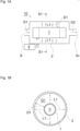
- Fig. 9A shows a gas decomposition device 50 of a third embodiment.
- Fig. 9B is a cross-sectional view taken along line S6-S6 of Fig. 9A .
- the gas decomposition device 50 includes a first light source 51 and an inside chamber 52.
- the inside chamber 52 is located inside the first light source 51.
- the first light source 51 has a double-tube structure in which an inner tube 54 is disposed inside an outer tube 53.
- an outside electrode 55 is disposed in contact with an outer wall surface of the outer tube 53
- an inside electrode 56 is disposed in contact with an inner wall surface of the inner tube 54.
- a space between the outer tube 53 and the inner tube 54 is filled with a light-emitting gas such as xenon gas and is sealed.
- a light-emitting gas such as xenon gas
- a discharge space 58 for the light-emitting gas is formed (refer to Fig. 9B ), and first light L1 is radiated (refer to Fig. 9A ).
- the inside electrode 56 and the outside electrode 55 have a mesh shape.
- the inner tube 54 is made of a material, such as quartz, that transmits the light-emitting gas.
- the light-emitting gas is transmitted through the inner tube 54 to reach the inside chamber 52.
- the gas decomposition device 50 has a gas supply port 3i on one end of the inside chamber 52 and a gas discharge port 3o on an other end of the inside chamber 52.
- the gas decomposition device continues to supply a gas G1 from the gas supply port 3i into the inside chamber 52, irradiate the gas G1, a gas to be treated, with the first light L1 emitted from the first light source 1, and discharge a gas G2 produced after irradiation with the light from the gas discharge port 3o. This allows N 2 O and a hydrocarbon in the gas G1 to be continuously decomposed.
- the outer tube 53 is made of, for example, quartz.
- the gas decomposition device 50 includes a reflective film 57 formed on an inner wall surface of the outer tube 53 to reflect the first light L1. Although the light-emitting gas can be radiated outward from the outer tube 53, the reflective film 57 formed on the inner wall surface of the outer tube 53 causes the first light L1 that otherwise travels outward from the outer tube 53 to reflect inward. This increases intensity of the light in the inside chamber 52.
- an outside diameter D1 of the outer tube 53 is preferably 10 mm or more and 50 mm or less, and more preferably, 20 mm or more and 40 mm or less.
- An outside diameter D2 of the inner tube 54 is preferably 2 mm or more and 20 mm or less, and more preferably, 4 mm or more and 10 mm or less.
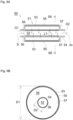
- Fig. 10 shows a gas decomposition device 60 of a first modification of the third embodiment. Differences between the gas decomposition device 60 and the gas decomposition device 50 of the third embodiment are that the gas decomposition device 60 does not have the reflective film 57 but has an outside chamber 2 outside the outer tube 53.
- the gas decomposition device 60 also has a gas supply port 4i on one end of the outside chamber 2 and a gas discharge port 4o on an other end of the outside chamber 2.
- the gas decomposition device supplies the gas G1 from the gas supply port 4i into the outside chamber 2 and irradiates the gas G1, a gas to be treated, with the first light L1 emitted from the first light source 1.
- the gas decomposition device 60 is designed to treat the gas G1 by both the inside chamber 52 and the outside chamber 2 and thus can treat a large amount of the gas, leading to improved efficiency of use of the first light L1.
- Fig. 11 shows a gas decomposition device 70 of a second modification of the third embodiment.
- a difference between the gas decomposition device 60 and the gas decomposition device 60 of the modification of the third embodiment is that the gas discharge port 3o of the inside chamber 52 is connected with the gas supply port 4i of the outside chamber 2.
- the gas G2 treated in the inside chamber 52 is treated again in the outside chamber 2. This makes it possible to treat the gas to be treated more effectively, leading to improved efficiency of use of the first light L1.
- the present modification shows an embodiment in which the gas first passes through the inside chamber 52 and then passes through the outside chamber 2.
- the gas may first pass through the outside chamber 2 and then pass through the inside chamber 52.
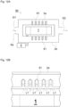
- Fig. 12A shows a gas decomposition device 80 of a fourth embodiment.
- the gas decomposition device 80 has a light guide 81 in an internal space of an outside chamber (2a, 2b) to allow light reaching the outside chamber (2a, 2b) to be transmitted through the light guide.
- the gas decomposition device has a gap between the outside chamber (2a, 2b) and a first light source 1 and thus has a gap between the light guide 81 and the first light source 1.
- the light guide 81 is formed in contact with a tube wall of the outside chamber (2a.2b).
- a gas e.g., nitrogen gas
- Fig. 12B is an enlarged view of the light guide 81 and its surroundings in Fig. 12A .
- the light guide 81 guides the first light L1 into an inside thereof and diffuses the first light L1 from a surface of the light guide 81. This leads to an increased area on which the first light L1 comes into contact with a gas G1 and improves effectiveness of photoreaction.
- Fig. 12C is a top view of the light guide 81 and is specifically a drawing of the light guide 81 in a first chamber 2a as viewed in a direction opposite the direction in which the first light L1 is emitted from the first light source 1.
- a portion of the light guide 81 has a circular cylinder shape, and a plurality of portions of the light guide are disposed in the first chamber 2a.
- the portions of the light guide 81 may be disposed regularly or irregularly.
- the portion of the light guide 81 may have any pillar shape (e.g., a polygonal or elliptic cylinder shape) other than the circular cylinder shape.
- the light guide 81 may have a plate shape.
- the light guide 81 may be disposed in an inside chamber.
- a first light source 1 was a xenon excimer lamp that was cylindrical and 800 mm in length.
- a chamber 2 was a cylindrical pipe having an inside diameter of 38 mm such that the first light source 1 was permitted to be disposed inside. Both sides of the pipe were sealed with sealing members that had either a gas inflow path or a gas outflow path.
- a power line connected to the first light source 1 passed through one of the sealing members. Lighting of the first light source 1 was controlled through the sealing member by a controller 5 that was located outside the chamber 2.
- Three types of gas G1 were prepared, and a gas decomposition process was conducted by sending each of the three types of the gas G1 to the gas decomposition device 10.
- a sample S1 was a gas in which 1000 ppm N 2 O was added to air.
- a sample S2 was a gas in which 1000 ppm CH 4 was added to air.
- a sample S3 was a gas in which 1000 ppm N 2 O and 1000 ppm CH 4 were added to air.
- Table 1 shows components (except for the air) contained in the samples S1 to S3 of the gas G1. [Table 1] Sample No. N 2 O Content (ppm) CH 4 Content (ppm) S1 1000 0 S2 0 1000 S3 1000 1000 1000
- Table 2 shows results of measured content of gas components of gas G2 discharged from a gas discharge port 3o of the gas decomposition device 40. Each gas component was measured by an FT-IR gas analyzer (model: MATRIX-5) manufactured by Bruker.
- N 2 O decreased from 1000 ppm to 423 ppm.
- the decreased amount of N 2 O was transformed into N 2 and O 2 as well as NOx (NO and NO2) and HNO 3 .
- NOx NO and NO2
- HNO 3 NOx
- O 3 was supposed to be generated by the first light source 1, but the gas G2 did not contain O 3 .
- a conceivable reason is that O 3 was consumed by a NOx cycle reaction.
- Results with the sample S2 show the following points. CH 4 was wholly oxidized and decomposed by the gas decomposition device 40, and CO 2 , H 2 O, and O 3 were generated. Regarding the H 2 O and CO 2 content of each sample, air included in the samples S1 to S3 of the gas G1 before treatment contained H 2 O and CO 2 , and thus not all the H 2 O and CO 2 content was generated by the decomposition reaction.
- the sample S3 was a sample in which CH 4 was added to the sample S1. It is considered that the added CH 4 hindered occurrence of a NOx cycle reaction consuming O 3 and that a sufficient quantity of O 3 and H 2 O caused NOx, which remained in the sample S1, to be transferred into HNO 3 . Since the added CH 4 was oxidized and decomposed and was transferred into CO 2 and H 2 O, the gas G2 did not contain CH 4 .
Landscapes
- Chemical & Material Sciences (AREA)
- Engineering & Computer Science (AREA)
- Health & Medical Sciences (AREA)
- Organic Chemistry (AREA)
- Chemical Kinetics & Catalysis (AREA)
- Oil, Petroleum & Natural Gas (AREA)
- General Chemical & Material Sciences (AREA)
- Analytical Chemistry (AREA)
- Toxicology (AREA)
- Biomedical Technology (AREA)
- Environmental & Geological Engineering (AREA)
- Inorganic Chemistry (AREA)
- Physics & Mathematics (AREA)
- General Health & Medical Sciences (AREA)
- Electromagnetism (AREA)
- Emergency Medicine (AREA)
- Physical Or Chemical Processes And Apparatus (AREA)
- Treating Waste Gases (AREA)
Abstract
Description
- The present invention relates to a gas decomposition method and a gas decomposition device.
- Since the average global temperature has been rising after the Industrial Revolution, taking measures against global warming is an urgent issue. It is known that greenhouse gases responsible for global warming include carbon dioxide, methane, dinitrogen monoxide, and chlorofluorocarbon gas. Among these gases, carbon dioxide emissions are the largest, followed by methane emissions and then dinitrogen monoxide emissions. However, it is reported that the global warming potential of methane is 25 times that of carbon dioxide and the global warming potential of dinitrogen monoxide is 298 times that of carbon dioxide. In particular, impact of dinitrogen monoxide emissions on global warming cannot be ignored.
- Great quantities of dinitrogen monoxide are discharged from industrial activities such as manufacturing of chemical products and combustion of waste as well as from human and livestock animal excreta treatment processes and agriculture. Methane is often discharged from the same sites as those for dinitrogen monoxide, such as agricultural land and places for livestock waste, biomass combustion, and sewage treatment. A reason why dinitrogen monoxide and methane are discharged from the same sites is that both gases are generated due to microorganisms in many cases. Since concentrations of dinitrogen monoxide and methane have recently been on the rise, suppressing a rise in or reducing concentrations of dinitrogen monoxide and methane is expected as a measure against global warming.
- In the sites where dinitrogen monoxide and methane are discharged, air makes up most of a composition of the discharged gas, and dinitrogen monoxide and methane often account for relatively low concentrations in the composition of the discharged gas. As methods for decomposing dinitrogen monoxide, a high temperature combustion technique and a catalyst technique have been used since past time. However, burning a gas by the high temperature combustion technique needs a large amount of energy. If a large amount of energy is secured using a fossil fuel, carbon dioxide emissions increase, and thus this technique is not an efficient method against global warming. The catalyst technique also requires heating a gas to a high temperature. In addition, ammonia needs to be procured for use in a catalyst or a reducing agent, and treating wastewater after decomposition processing is a challenge. As a result, the catalyst technique is not efficient either. As methods for decomposing methane, a high temperature combustion technique and a catalyst technique are known. However, challenges as described above exist. Another method of decomposition is a plasma technique. Unfortunately, if both a gas containing a nitrogen atom, such as nitrogen or dinitrogen monoxide, and a gas containing an oxygen atom, such as oxygen, are contained in a gas to be treated, NOx and dinitrogen monoxide, which are environmental contaminants, are generated in large quantities by plasma. This limits a composition of the gas to be treated.
- As a new method for decomposing dinitrogen monoxide, a method of decomposing dinitrogen monoxide by ultraviolet irradiation is known. For example, in
Patent Document 1, an engine exhaust purification system capable of decomposing dinitrogen monoxide is described. The system, which is designed to decompose and remove dinitrogen monoxide by ultraviolet light of 172 nm after oxidizing a hydrocarbon and CO in exhaust gas from an engine, removing NOx, and removing water vapor, is described. - Patent Document 1:
JP-A-2021-088964 - A method for dinitrogen monoxide purification disclosed in
Patent Document 1 presents a very complicated structure and is not efficient. Hence, the present invention provides a gas decomposition method and a gas decomposition device that are designed to efficiently decompose a greenhouse gas by a simpler way or structure. - A gas decomposition method according to the present invention includes irradiating a gas to be treated containing oxygen, dinitrogen monoxide, and a saturated hydrocarbon with first light having a main emission wavelength in a range of 160 nm or more and less than 200 nm to decompose the dinitrogen monoxide and the saturated hydrocarbon.
- In the present specification, "oxygen" simply referred to as "oxygen" represents an "oxygen molecule" (hereinafter sometimes referred to as "O2"). The saturated hydrocarbon may be a type of hydrocarbon or two or more types of hydrocarbons. Although details will be described later, the first light serves to directly decompose dinitrogen monoxide (hereinafter sometimes referred to as "N2O"), and an excited oxygen atom (sometimes referred to as "singlet oxygen" or "O(1D)"; hereinafter sometimes referred to as "O(1D)") generated by irradiation with the first light serves to decompose N2O. O(1D) generated by irradiation with the first light and an oxygen atom in a ground state (sometimes referred to as "triplet oxygen" or "O(3P)"; hereinafter sometimes referred to as "O(3P)") serve to decompose the hydrocarbon. Consequently, both N2O and the hydrocarbon can be decomposed by the first light. Water (H2O) generated by decomposition reaction of the hydrocarbon promotes nitration of NOx generated by the decomposition of N2O. Since NOx is a substance that adversely impacts a human body and animals, it is preferable to reduce NOx from an environmental preservation perspective. Further, O(1D) generated by the decomposition of N2O contributes to the decomposition of the hydrocarbon. In this respect, it is preferable to decompose a hydrocarbon concurrently with the decomposition of N2O.
- Through nitration of NOx, nitric acid (hereinafter sometimes referred to as "HNO3") is obtained. Since nitric acid is a useful substance in various industrial sectors, nitric acid is produced on an industrial scale using a large amount of energy. In contrast to this, the gas decomposition method enables generation of nitric acid without a large amount of energy. This produces a secondary effect by allowing generated nitric acid to be collected and used.
- The saturated hydrocarbon may be an alkane. The alkane may have 10 or less, 6 or less, or 4 or less carbon atoms.
- A temperature of the gas to be treated being irradiated with the first light may be higher than the temperature of the gas to be treated before being collected. In other words, the collected gas to be treated may be heated. As methods of heating, there are a method using heat energy from at least one of a first light source and a second light source describe later or using heat of reaction from each chemical reaction and a method using a heater for heating the gas to be treated.
- The gas to be treated may contain water (H2O). In the present specification, water conceptually includes water vapor as a gas and water mist as a liquid. Although details will be described later, if the gas to be treated contains water, water (H2O) is photolyzed by the first light or irradiation with the first light to generate a hydroxy radical (hereinafter sometimes referred to as "OH"). The hydroxy radical promotes decomposition of the hydrocarbon. As described above, water promotes nitration of NOx generated by the decomposition of N2O.
- The alkane may primarily contain methane. As described above, similarly to N2O, methane is one of greenhouse gases. The present inventors have found that dinitrogen monoxide and methane, two types of greenhouse gases, can be simultaneously reduced by irradiation with the first light. A hydrocarbon that primarily contains methane refers to a hydrocarbon having a largest methane gas concentration (vol%) among alkane hydrocarbons having 4 or less carbon atoms.
- Although details will be described later, a combination of dinitrogen monoxide and methane is discharged, despite relatively low concentrations, from a sewer or a septic tank, or a biomass plant or a waste treatment plant. Kinds of waste that contain raw garbage or human and livestock animal excreta often contain a hydrocarbon and ammonia. Thus, in general, when these kinds of waste become rotten, both dinitrogen monoxide derived from ammonia and methane derived from a hydrocarbon are generated. This allows both dinitrogen monoxide and methane to be procured from a common location. Dinitrogen monoxide and methane may be procured from different locations.
- The methane may occupy 20 vol% or more with respect to the dinitrogen monoxide. If a ratio of methane to dinitrogen monoxide is relatively high, a higher amount of water is generated from hydrogen and oxygen derived from the methane. This makes it possible to promote nitration of NOx, which is generated as a by-product of the decomposition of N2O, and consequently reduce an amount of NOx, a harmful substance.
- The gas to be treated may be irradiated with second light having a main emission wavelength in a range of 200 nm or more and less than 1180 nm. In other words, by the irradiation with the second light having a wavelength longer than that of the first light, O(1D) or O(3P) is generated from ozone (hereinafter sometimes referred to as "O3") secondarily generated by irradiation with the first light. O(1D) is used to decompose N2O, decompose the hydrocarbon, and generate a hydroxy radical. O(3P) is used to nitrate NOx and decompose the hydrocarbon.
- The second light may have a main emission wavelength in a range of 780 nm or more and less than 1180 nm. In other words, the second light may primarily contain infrared light. The infrared light helps to increase the temperature of the gas to be treated and promote the decomposition of the hydrocarbon.
- Nitric acid may be generated from the decomposed gas to be treated.
- A gas decomposition device according to the present invention includes: a chamber to supply a gas to be treated containing oxygen, dinitrogen monoxide, and a saturated hydrocarbon; and a first light source to irradiate the chamber with first light having a main emission wavelength in a range of 160 nm or more and less than 200 nm. The gas decomposition device decomposes the dinitrogen monoxide and the saturated hydrocarbon.
- The chamber may include an inside chamber located inside the first light source and an outside chamber disposed so as to surround the first light source. In the present specification, the "chamber" simply presented as-is (including a case where the term is presented together with a reference sign) refers to an outside chamber disposed so as to surround the first light source. In the present specification, for a description of the inside chamber located inside the first light source, an "inside chamber" is presented, or a chamber disposed inside a light source is stated.
- The saturated hydrocarbon may be an alkane. The alkane may have 10 or less, 6 or less, or 4 or less carbon atoms.
- The chamber may have a connection port connected to a space in which a gas containing 5 vol% or less of the dinitrogen monoxide and 5 vol% or less of an alkane having 4 or less carbon atoms is present. The "space in which a gas containing 5 vol% or less of the dinitrogen monoxide and 5 vol% or less of an alkane having 4 or less carbon atoms is present" is, for example, a sewer or a septic tank, or a drainage pipe, a drainage tank, an exhaust pipe, and an exhaust tank of a biomass plant or a waste treatment plant. Even in a case where dinitrogen monoxide and the alkane each have a low concentration of 1% or less, decomposition of the dinitrogen monoxide and the alkane is possible. Even in a case where at least one of the concentration of dinitrogen monoxide and the concentration of the alkane is more than 5 vol%, decomposition of the dinitrogen monoxide and the alkane is possible.
- The chamber may be an outside chamber surrounding the first light source, and the gas decomposition device may supply the gas to be treated to the outside chamber.
- The gas to be treated supplied to the outside chamber may not come into contact with the first light source. A gap between the outside chamber and the first light source may be filled with a gas (such as nitrogen gas acting as an inert gas) that is less likely to be absorbed by the first light.
- The gas decomposition device may include a second light source external to the outside chamber to irradiate the gas to be treated with light having a main emission wavelength in a range of 200 nm or more and less than 1180 nm, the gas to be treated being located between the outside chamber and the first light source.
- The chamber may be an inside chamber located inside the first light source, and the gas decomposition device may supply the gas to be treated to an interior of the inside chamber.
- The chamber may include both an inside chamber located inside the first light source and an outside chamber surrounding the first light source, and the gas decomposition device may supply the gas to be treated to an interior of the inside chamber and a space between the outside chamber and the first light source.
- The gas to be treated may pass through one of the interior of the inside chamber and the space between the outside chamber and the first light source, and may subsequently pass through an other of the interior of the inside chamber and the space between the outside chamber and the first light source.
- The gas decomposition device may include a light guide in an internal space of the chamber, the light guide being configured to transmit light reaching the chamber. The light guide may have a pillar shape or a plate shape.
- The gas decomposition device may include a gap between the light guide and the first light source. The gas decomposition device may not include a gap between the light guide and the first light source.
- The first light source may be an excimer lamp. A main wavelength of light from the excimer lamp may be 172 nm or near 172 nm. Such excimer light is obtained by turning on a xenon excimer lamp in which xenon gas is sealed in an arc tube. The excimer lamp is a light source that can be stably mass-produced, and has a high cost reduction effect. Electric power supplied to the excimer lamp is controlled by a controller. The controller controls turning on and off of the excimer lamp.
- In the present specification, "near 172 nm" refers to a region in the range of 172 nm ±5 nm. In this specification, on condition that a wavelength range Z(λ) of ±10 nm with respect to a certain wavelength λ is defined on an emission spectrum, the "main wavelength" indicates a wavelength λi in a wavelength range Z(λi) showing integrated intensity of 40% or more with respect to the total integrated intensity in the emission spectrum. When the light source that emits light having the "main wavelength" is a xenon excimer lamp or such a light source having an extremely narrow half-value width and showing high light intensity only at specific wavelengths, a wavelength representing the highest relative light intensity (peak wavelength) may be usually regarded as the main wavelength.
- The technique described above makes it possible to provide a gas decomposition method and a gas decomposition device that are designed to efficiently decompose a greenhouse gas by a simpler way or structure. The provision of such a gas decomposition method and gas decomposition device greatly contributes to
Goal 13 "Take urgent action to combat climate change and its impacts" of the Sustainable Development Target (SDGs) led by the United Nations. -
-
Fig. 1A is a diagram showing a first embodiment of a gas decomposition device. -
Fig. 1B is a cross-sectional view taken along line S1-S1 ofFig. 1A . -
Fig. 2 is a diagram showing an example of a method for treating nitric acid. -
Fig. 3 is a graph showing a relationship between methane gas temperature and reaction rate constant. -
Fig. 4A is a graph showing a relationship between a ratio of CH4 to N2O and an amount of NOx generated. -
Fig. 4B is a graph showing a relationship between a ratio of CH4 to N2O and an amount of NOx generated. -
Fig. 5A is a diagram showing a first modification of the first embodiment. -
Fig. 5B is a cross-sectional view taken along line S2-S2 ofFig. 5A . -
Fig. 6A is a diagram showing a second modification of the first embodiment. -
Fig. 6B is a cross-sectional view taken along line S3-S3 ofFig. 6A . -
Fig. 7A is a diagram showing a second modification of the first embodiment. -
Fig. 7B is a cross-sectional view taken along line S4-S4 ofFig. 7A . -
Fig. 8A is a diagram showing a second embodiment. -
Fig. 8B is a cross-sectional view taken along line S5-S5 ofFig. 8A . -
Fig. 9A is a diagram showing a third embodiment. -
Fig. 9B is a cross-sectional view taken along line S6-S6 ofFig. 9A . -
Fig. 10 is a diagram showing a first modification of the third embodiment. -
Fig. 11 is a diagram showing a second modification of the third embodiment. -
Fig. 12A is a diagram showing a fourth embodiment. -
Fig. 12B is an enlarged view of a principal part ofFig. 12A . -
Fig. 12C is a top view of a light guide. -
Fig. 13 is a diagram showing experimental equipment. - Embodiments of the present invention will be described with reference to the drawings as appropriate. Note that all the drawings other than graphs are schematically illustrated, the dimensional ratios in the drawings do not necessarily coincide with the actual dimensional ratios, and the dimensional ratios do not necessarily coincide between the drawings.
-
Fig. 1A is a diagram showing a first embodiment of a gas decomposition device.Fig. 1B is a cross-sectional view taken along line S1-S1 ofFig. 1A . Agas decomposition device 10 includes achamber 2 and a firstlight source 1 disposed in thechamber 2 to emit first light L1 having a main emission wavelength in a range of 160 nm or more and less than 200 nm. Thechamber 2 includes agas supply port 3i and a gas discharge port 3o. Thegas supply port 3i and the gas discharge port 3o are disposed opposite to each other through the firstlight source 1. In the present specification, the first light L1 emitted from the firstlight source 1 is indicated, for example, by solid arrows directed outward from the firstlight source 1. - The gas decomposition device continues to supply a gas G1 from the
gas supply port 3i into thechamber 2, irradiate the gas G1, a gas to be treated, with the first light L1 emitted from the firstlight source 1, and discharge a gas G2 produced after irradiation with the light from the gas discharge port 3o. This allows N2O and a hydrocarbon in the gas G1 to be continuously decomposed. The firstlight source 1 is electrically connected to acontroller 5. With electric power supplied from thecontroller 5 to the firstlight source 1, the firstlight source 1 is lit. - In the preset embodiment, the first
light source 1 is a xenon excimer lamp that emits excimer light having a peak wavelength of 172 nm. In the xenon excimer lamp of the present embodiment, xenon gas is sealed in an inside 1i (refer toFig. 1B ) of an arc tube. The arc tube of the present embodiment has a cylindrical shape. However, a shape of the arc tube is not limited to the cylindrical shape. The firstlight source 1 is not limited to the excimer lamp, but may be, for example, a low-pressure mercury lamp. The firstlight source 1 may be an excimer lamp in which a gas other than xenon is sealed. The firstlight source 1 may be a solid state light source such as a light-emitting diode (LED) or a laser diode (LD). - The first light L1 is readily absorbed into the gas G1 and does not carry a long way. Thus, a space D1 between a surface of the arc tube of the first
light source 1 and an inner wall of the chamber 2 (refer toFig. 1A or Fig. 1B ) is relatively narrow. The space D1 may be, for example, 50 mm or less and is preferably 30 mm or less. With the space D1 set at an appropriate distance such that the light is not too attenuated, the gas decomposition device can reduce the gas G1 that passes through thechamber 2 without being irradiated with the first light L1. - The gas to be treated will be described. The gas G1, a gas to be treated, contains oxygen, N2O, and a saturated hydrocarbon, particularly an alkane having 10 or less, 6 or less, or 4 or less carbon atoms.
- The oxygen contained in the gas G1 may be oxygen in air. In other words, the gas G1 may contain air. The gas G1 containing air inevitably contains nitrogen and a small amount of carbon dioxide. The gas G1 may contain water.
- If the saturated hydrocarbon is an alkane having 4 or less carbon atoms, examples of the alkane having 4 or less carbon atoms include methane (hereinafter sometimes referred to as "CH4"), ethane (C2H6), propane (C3H8), and butane (C4H10). The "alkane having 4 or less carbon atoms" may contain a type of hydrocarbon or two or more types of hydrocarbons. Among these hydrocarbons, CH4 is a greenhouse gas that has a higher global warming potential than that of carbon dioxide.
When the gas to be treated contains both N2O and CH4, two types of the greenhouse gases can be reduced simultaneously. - A mechanism for decomposing N2O by ultraviolet light will be described. A method of decomposing N2O is made up of direct decomposition by ultraviolet light and indirect decomposition with O(1D) generated by ultraviolet light.
- Direct decomposition of N2O will be described. When N2O is irradiated with ultraviolet light hv at a wavelength of 340 nm or less (≤ 340 nm), N2O is decomposed, and N2 and O(1D) are generated. This is represented by the formula (1):
N2O + hv (≤ 340 nm) → N2 + O (1D) ... (1)
- The decomposition reaction of the formula (1) occurs in theory by ultraviolet light having a wavelength of 340 nm or less. However, an absorption cross section of N2O for the light having a wavelength of 200 nm or more is small. Thus, using the light having a wavelength of less than 200 nm, for which the absorption cross section is relatively large, is more efficient in promoting the decomposition reaction of the formula (1).
- Next, indirect decomposition of N2O will be described. O(1D) is a highly active agent that has high reactivity. When O(1D) generated by ultraviolet light comes into contact with N2O, an oxygen molecule and a nitrogen molecule are generated by the formula (2), or nitrogen monoxide (hereinafter sometimes referred to as "NO") is generated by the formula (3).
N2O + O (1D) → Oz + N2 ... (2)
N2O + O (1D) → NO + NO ... (3)
- O(1D) necessary for reactions by the formulas (2) and (3) is generated by the formula (1) as well as the following formulas (4) and (5). "hv (≤ 175 nm)" represents ultraviolet light having a wavelength of 175 nm or less, and "hv (≤ 411 nm)" represents ultraviolet light having a wavelength of 411 nm or less.
O2 + hv (≤ 175 nm) → O (3P) + O (1D) ... (4)
O3 + hv (≤ 411 nm) → O (1D) + O2 ... (5)
- O3 necessary for a reaction by the formula (5) is generated through reactions represented by the following formulas (1), (4), (6), (7), (8) (the formulas (1) and (4) are described again). The formula (6) shows that a reaction represented by the formula (6) occurs if the wavelength of the ultraviolet hv is 242 nm or less. "M" included in the formulas (7) and (8) indicates a third body.
N2O + hv (≤ 340 nm) → N2 + O (1D) ... (1)
O2 + hv (≤ 175 nm) → O (3P) + O (1D) ... (4)
O2 + hv (≤ 242 nm) → O (3P) + O (3P) ... (6)
O(1D) + M → O (3P) + M ... (7)
O2 + O (3P) + M → O3 + M ... (8)
- Direct decomposition of N2O by the ultraviolet light hv and indirect decomposition of N2O with O(1D) generated by the ultraviolet light have been described above. In general, both direct decomposition and indirect decomposition are conducted. A ratio of occurrence of direct decomposition to occurrence of indirect decomposition differs depending on a gas composition of the gas G1.
- Meanwhile, a series of the reactions descried above generates a by-product. NO generated through the reaction by the formula (3) causes a reaction as described below in the
chamber 2. This reaction is represented by the following formulas (9) to (14).
NO + O (3P) → NO2 ... (9)
NO + O3 + M → NO2 + O2 + M ... (10)
NO2 + O (3P) + M → NO3 + M ... (11)
NO2 + 03 + M → NO3 + Oz + M ... (12)
NO3 + NO2 → N2O5 ... (13)
N2O5 + H2O → HNO3 + HNO3 ... (14)
- NO is converted into nitrogen dioxide (hereinafter sometimes referred to as "NO2") by any of the formulas (9) and (10). When O3 and H2O are satisfactorily present in the
chamber 2, NO2 is converted into nitric acid (HNO3) via NO3 and N2O5 by the formulas (11) to (14). If O3 and H2O are not satisfactorily present in the chamber, reactions by the formulas (12) and (14) do not occur satisfactorily and conversion to nitric acid does not occur. Occurrence of a NOx cycle reaction causes O3 to be consumed and O3 can be depleted. In this case, NOx remains behind. - The NOx cycle reaction will be described. In the present specification, NOx conceptually includes NO and NO2. NO is converted into NO2 by any of the formulas (9) and (10) described again below. Meanwhile, NO2 reacts with an oxygen atom O to generate NO by the following formula (15). The oxygen atom O included in the formula (15) includes both O(1D) and O(3P).
NO + O (3P) → NO2 ... (9)
NO + O3 + M → NO2 + O2 + M ... (10)
NO2 + O → NO + O2 ... (15)
- The reaction particularly by the formula (10) to generate NO2 from NO and the reaction by the formula (15) to generate NO from NO2 can be repeated. This refers to the NOx cycle reaction. In a process of the NOx cycle reaction, oxygen atoms O necessary for decomposition of N2O and the hydrocarbon and O3 necessary for generation of O(1D) (refer to the formula (5)) continue to be consumed. Thus, occurrence of the NOx cycle reaction causes the oxygen atoms O and O3 to disappear and hinders the decomposition of N2O and the hydrocarbon.
- NOx adversely impacts a human body and animals. Hence, it is desirable to create an environment where O3 and H2O are satisfactorily present in the chamber and promote the reaction for generating nitric acid (HNO3) from NOx. Oz and H2O need to be present in a space irradiated with the light to make O3 and H2O be satisfactorily present. In other words, a large amount of O2 needs to be contained in the gas G1, a gas to be treated. A method of making H2O be satisfactorily present is a method of making the gas G1 contain the hydrocarbon. Although details will be described later, a chemical reaction between the hydrocarbon and hydroxyl radicals contributes to the generation of H2O. It is also preferable to make the gas G1 contain H2O.
-
Fig. 2 shows an example of a method for treating nitric acid. InFig. 2 , a gas G2 containing nitric acid generated by thegas decomposition device 10 is discharged from thechamber 2. The gas G2 passes through adischarge pipe 11 connected to the gas discharge port 3o and comes into contact with water W1 in acontainer 12. The nitric acid contained in the gas G2 is thereby dissolved in the water W1, resulting in an aqueous solution of nitric acid. This consequently allows the nitric acid to be trapped. Nitric acid is a raw material for ammonium nitrate and is a useful substance in such a field as the chemical industry and agricultural sector. Thus, the aqueous solution of nitric acid may be collected from thecontainer 12. If a concentration of the aqueous solution of nitric acid is low to such a degree that the aqueous solution is permitted to be drained, the aqueous solution may be poured into a sewer without being collected. The nitric acid poured into the sewer is eventually converted into N2 via NO3 - by biodegradation. InFig. 2 , a method of making the nitric acid be dissolved into the water W1 and collecting the aqueous solution is described. However, a method may include simply cooling the gas G2 to liquefy the nitric acid and collecting the liquefied nitric acid. Nitric acid has a boiling point of about 83°C, and thus when the gas is cooled, the nitric acid is liquefied from the gas. - A mechanism for decomposing a saturated hydrocarbon by ultraviolet light will be described. A case in which the saturated hydrocarbon is CH4 will be described below. However, saturated hydrocarbons other than CH4 can be described in the same way as below.
- CH4 is decomposed through chemical reactions represented by the following formulas (16) to (19).
CH4 + O (1D) → CH3 + OH ... (16)
CH4 + O (1D) → CH2O + H2 ... (17)
CH4 + O (3P) → CH3 + OH ... (18)
CH4 + OH - CH3 + H2O ... (19)
- O(1D) and O(3P) are each generated by the formula (1), (4), (5), (6), or (7) described above. OH used in the formula (19) is generated by the formulas (16) and (18) as well as the following formulas (20) and (21).
H2O + hv (≤ 242 nm) → H + OH ... (20)
H2O + O (1D) → OH + OH ... (21)
- Thus, CH4 is decomposed by O('D), O(3P), or OH generated by irradiation with ultraviolet light. O(1D) generated by irradiation with ultraviolet light is used to both decompose N2O and decompose CH4. This makes it possible to simultaneously perform the processes of decomposition. Further, as shown with the formula (1), O(1D) obtained by decomposition of N2O can be used to decompose CH4. Performing the process of decomposition of CH4 simultaneously with the process of decomposition of N2O enables efficient decomposition. This is one of advantageous characteristics of cases in which CH4 is mainly contained as a saturated hydrocarbon.
- Out of CH4 decomposition reactions, reactions by the formulas (18) and (19) described again below depend on temperature.
Fig. 3 is a graph showing a relationship between methane gas temperature T1 and reaction rate constant k. InFig. 3 , an R1 curve represents a reaction rate constant k (m3/kmol s) with respect to a temperature T1 (°C) for the formula (19). InFig. 3 , an R2 curve represents a reaction rate constant k (m3/kmol s) with respect to a temperature T1 (°C) for the formula (18). The R1 and R2 curves illustrate that both the reactions by the formulas (18) and (19) increase in reactivity with a rise in temperature.
CH4 + O (3P) → CH3 + OH ... (18)
CH4 + OH → CH3 + H2O ... (19)
- Further, a rise in temperature causes an amount of O(3P) generated by the formula (7) described again below to increase. This incremental phenomenon results from decomposition of ozone by heat. The increased O(3P) promotes the CH4 decomposition reaction by the formula (18) described again below.
O (1D) + M → O (3P) + M ... (7)
CH4 + O (3P) → CH3 + OH ... (18)
- In the present embodiment, the first
light source 1 is disposed in thechamber 2. The firstlight source 1 is lit, and emits ultraviolet light and generates heat. Hence, the firstlight source 1 heats the gas around the firstlight source 1, increases temperature of the gas G1 containing CH4, and promotes the CH4 decomposition reactions by the above formulas (18) and (19). In addition, the formulas (2), (3), (9), and (10) represent exothermic reaction and increase the temperature of the gas G1. Thus, performing the process of decomposition of CH4 simultaneously with the process of decomposition of N2O enables efficient decomposition. In the same way as CH4, decomposition reactions of saturated hydrocarbons other than CH4 have dependence on temperature. -
Fig. 4A shows a result determined by a simulation, representing a relationship between a ratio of CH4 to N2O and an amount of NOx generated. The "ratio of CH4 to N2O" is indicated by a percentage (unit: vol%) representing the ratio of a volume of CH4 to a volume of N2O contained in the gas to be treated. The "amount of NOx generated" represents a sum of an amount of NO generated and an amount of NO2 generated. R3 to R5 curves differ in N2O content. For the R3 curve, the N2O content is 10000 ppm. For the R4 curve, the N2O content is 1000 ppm. For the R5 curve, the N2O content is 100 ppm. For the R3 to R5 curves, the temperature of the gas G1 in thechamber 2 is standardized at 500 K. InFig. 4A , plots at places where two or more plots overlap or are adjacent to each other are partially omitted to improve graph legibility. All the R3 to R5 curves are simulated at a common rate across the horizontal axis. The partially omitted plots should be read as being present on the curves. - Preferably, the amount of NOx generated is low.
Fig. 4A indicates that the amount of NOx generated decreases with an increase in the ratio of CH4 to N2O regardless of the N2O amount. The graph shows that NOx is not generated when 10 vol% or more CH4 is present relative to N2O. This is due to satisfactory supply of the hydrocarbon and consequent nitration of NOx by H2O generated by decomposition of the hydrocarbon. -
Fig. 4B shows a result determined by a simulation, representing a relationship between a ratio of CH4 to N2O and an amount of NOx generated. Definitions of the "ratio of CH4 to N2O" and the "amount of NOx generated" are the same as those inFig. 4A . R6 to R9 curves differ in temperature of the gas G1 inside thechamber 2. For the R6 curve, the temperature is 350 K. For the R7 curve, the temperature is 400 K. For the R8 curve, the temperature is 450 K. For the R9 curve, the temperature is 500 K. For the R6 to R9 curves, a flow rate of N2O is standardized at 10,000 ppm. -
Fig. 4B indicates that the amount of NOx generated decreases with an increase in temperature inside thechamber 2. It is also indicated that the amount of NOx generated decreases with an increase in the ratio of CH4 to N2O. The graph shows that NOx is not generated even with a temperature of 350 K when 20 vol% or more CH4 is present relative to N2O. This result is due to satisfactory supply of the hydrocarbon resulting from a high temperature or a high ratio of CH4 and consequent nitration of NOx by H2O generated by decomposition of the hydrocarbon. - According to
Figs. 4A and 4B , it is preferable that the ratio of CH4 to N2O be 20 vol% or more. A ratio of 20 vol% or more readily causes the amount of NOx generated to decrease. InFig. 4A , a simulation was performed with the N2O content ranging from 100 ppm to 10,000 ppm and corresponding amounts of CH4, whereas, inFig. 4B , a simulation was performed with the 10,000 ppm N2O content and a corresponding amount of CH4. However, even N2O of less content (e.g., less than 100 ppm) and a corresponding amount of CH4 can produce similar effects. Even a saturated hydrocarbon other than CH4 can produce similar effects. - A method of using the
gas decomposition device 10 will be described. Dinitrogen monoxide is discharged from human and animal excreta, agricultural and livestock farms, as well as through a process of fermenting biomass or raw garbage by microorganisms. On the other hand, methane is produced by anaerobic methanogen, which exists in places such as digestive organs in animals, bogland, marine sediment, and the earth's crust. Thus, both dinitrogen monoxide and methane exist, as described above, in places such as a sewer or a septic tank, or a drainage pipe, a drainage tank, an exhaust pipe, and an exhaust tank of a biomass plant or a waste treatment plant. Microorganisms also release oxygen dioxide. However, in the case of a sewer or a septic tank, oxygen having a concentration close to the concentration in the air (about 21 vol%) and a large amount of water are contained by the treatment of aerating with a large amount of air. - Therefore, the
gas supply port 3i of thegas decomposition device 10 is connected to a sewer or a septic tank, or a drainage pipe, a drainage tank, an exhaust pipe, an exhaust tank, or the like of a biomass plant, a waste treatment plant, or a chemical plant. This allows both dinitrogen monoxide and methane to be procured from a common location. In many cases, most of the gas to be treated is air, and a proportion of each of dinitrogen monoxide and the hydrocarbon in the gas to be treated is 5 vol% or less. However, the decomposition method according to the present invention can decompose even a low-concentration gas to be treated having a concentration of such as 5 vol% or less. The gas to be treated may have a concentration of 1 vol% or less. - The same applies to hydrocarbons other than methane.
- A first modification of the first embodiment will be described. Hereinafter, matters different from the first embodiment will be mainly described, and description of matters common to the first embodiment will be omitted. The same applies to modifications described later and second and later embodiments.
-
Fig. 5A shows agas decomposition device 15 of the first modification.Fig. 5B is a cross-sectional view taken along line S2-S2 ofFig. 5A . As shown inFigs. 5A and 5B , the firstlight source 1 is disposed in thechamber 2 of thegas decomposition device 15. The firstlight source 1 is covered with anultraviolet transmissive tube 6. Theultraviolet transmissive tube 6 transmits the first light L1 emitted from the firstlight source 1. If the firstlight source 1 is not covered with theultraviolet transmissive tube 6, the firstlight source 1 can be exposed to the gas G1, resulting in adhesion of a solid component (e.g., a carbide) of the gas G1 to the surface of the arc tube of the firstlight source 1. When the firstlight source 1 is covered with theultraviolet transmissive tube 6, the solid component of the gas G1 does not adhere to the firstlight source 1. When a solid component has adhered to theultraviolet transmissive tube 6 and a reduction in irradiance is feared, theultraviolet transmissive tube 6 may be replaced with an ultraviolet transmissive tube that no such a solid component has adhered to. Theultraviolet transmissive tube 6 may be regularly replaced. An inside of theultraviolet transmissive tube 6 may be filled with nitrogen. - The
ultraviolet transmissive tube 6 may be made of, for example, quartz glass. Theultraviolet transmissive tube 6 may cover the firstlight source 1 wholly or not wholly. Theultraviolet transmissive tube 6 may be configured so as to cover at least the arc tube of the firstlight source 1. -
Fig. 6A shows agas decomposition device 20 of a second modification.Fig. 6B is a cross-sectional view taken along line S3-S3 ofFig. 6A . As shown inFigs. 6A and 6B , thegas decomposition device 20 includes afirst chamber 2a and asecond chamber 2b that are made by branching a gas flow path into two. The firstlight source 1 is disposed outside thefirst chamber 2a and thesecond chamber 2b. Because the firstlight source 1 is outside the chamber (2a, 2b), a solid component of the gas G1 does not adhere to the firstlight source 1, and the firstlight source 1 can be readily subjected to maintenance, inspection, and replacement. - In the
gas decomposition device 20, thefirst chamber 2a and thesecond chamber 2b are disposed such that the firstlight source 1 is put between the first and the second chambers. The first light L1 from the firstlight source 1 can be guided to the first and thesecond chambers light source 1, thefirst chamber 2a, and thesecond chamber 2b of the present embodiment each have a flat rectangular cross section. The first light L1 emitted from the firstlight source 1 travels a short distance outside each of the chambers (2a, 2b). This renders an amount of attenuation of the first light L1 small and helps the first light L1 to reach the chambers (2a, 2b) evenly. - It is more preferable that a space between the first
light source 1 and each of the first and thesecond chambers light source 1. This helps to suppress absorption of the first light L1 outside the chambers (2a, 2b). - In the present embodiment, the chambers (2a, 2b) are constituted of a quartz glass tube that transmits the first light L1. However, not all the housings constituting the chambers (2a, 2b) may be made of the ultraviolet light transmitting material. At least a portion of the chamber required to transmit the first light L1 is preferably made of the ultraviolet light transmitting material such as quartz glass. The
gas decomposition device 20 may include three or more chambers that are made by branching a gas flow path into three or more. -
Fig. 7A shows agas decomposition device 25 of a third modification.Fig. 7B is a cross-sectional view taken along line S4-S4 ofFig. 7A . As shown inFigs. 7A and 7B , thegas decomposition device 25 includes aheater 7 wrapped around an outside of thechamber 2 that has a cylindrical shape. The firstlight source 1 is disposed in thechamber 2. - As described above, an increase in the temperature of the gas G1 contributes to efficient decomposition and decreased generation of NOx. In the first embodiment described above, the gas G1 is heated by heat radiated from the excimer lamp. In addition, as in the
gas decomposition device 25 of the present modification, theheater 7 may be disposed in a gas decomposition device to heat the gas G1. Theheater 7 of the present embodiment is a sheathed heater designed to convert electric energy into heat and heat the gas. Preferably, the electric energy is renewable energy.
Theheater 7 disposed decomposes ozone and thus has a secondary effect of lowering emissions of ozone into the atmosphere. - The
heater 7 may constitute fluid heating through a heat medium flow path or a heat pipe. Theheater 7 may be disposed upstream of the firstlight source 1 to guide the gas G1 heated at high temperature to thegas supply port 3i. Theheater 7 may be sunlight or a fluid heated by sunlight. -
Fig. 8A shows a second embodiment.Fig. 8B is a cross-sectional view taken along line S5-S5 ofFig. 8A . Agas decomposition device 30 of the present embodiment includes a plurality of secondlight sources 8. The plurality of the secondlight sources 8 emit second light L2 toward achamber 2. In the present specification, the second light L2 emitted from the secondlight sources 8 is indicated, for example, by broken arrows directed outward from the secondlight sources 8. Preferably, the secondlight sources 8 are each disposed such that a space to be irradiated with the second light L2 overlaps a space to be irradiated with first light L1. - A wavelength of the second light L2 emitted from the second
light sources 8 differs from a wavelength of the first light L1 emitted from the firstlight source 1. The wavelength of the second light L2 is longer than that of the first light L1. The second light L2 generates O(1D) or O(3P) from O3 as represented by the following formulas (21) and (22).
O3 + hv (≤ 411 nm) → O (1D) + O2 ... (21)
O3 + hv (≤ 1180 nm) → O (3P) + O2 ... (22)
- The formulas (21) and (22) show that an activity state of the generated oxygen atom differs depending on the wavelength of the second light L2. When the second light L2 is ultraviolet light having a wavelength of less than 411 nm, O(1D), which is highly active, is generated. O(1D) generated by the formula (21) is used for decomposition of N2O (refer to the formulas (2) and(3)), decomposition of a hydrocarbon (refer to the formulas (15) and (16)), and generation of the hydroxy radical (refer to the formula (20)).
- When the second light L2 is infrared light or visible light having a wavelength of less than 1180 nm, O(3P), which is less active, is generated. O(3P) generated is used for decomposition of a hydrocarbon (refer to the formula (17)) and nitration of NOx (refer to the formulas (9) and (11)). In this way, by irradiation of a gas G1 with the second light L2, decomposition of N2O and CH4 by the first light L1 is promoted.
- The second
light sources 8 may each be any of an excimer lamp, a solid state light source such as an LED or an LD, a low-pressure mercury lamp, and a fluorescent lamp. The secondlight sources 8 may be lamps that emit ultraviolet light, visible light, or infrared light. When the secondlight sources 8 are lamps that emit infrared light, heating the gas makes it possible to produce an effect of promoting decomposition reaction, as described in the third modification of the first embodiment. If aheater 7 is disposed to add heating, the generation of O(3P) by infrared light caused by thedisposed heater 7 makes it possible to produce the effect of promoting decomposition reaction. - As shown in
Figs. 8A and 8B , in a case where one of the firstlight source 1 and the secondlight sources 8 is disposed inside thechamber 2, it is preferable to dispose the firstlight source 1 inside thechamber 2. This is because the light emitted from the firstlight source 1 has a wavelength shorter than that of the light emitted from the secondlight sources 8, and thus the light emitted from the firstlight source 1 is less likely to be transmitted through thechamber 2 as compared to the light emitted from the secondlight sources 8. In order to increase transmittance to the light emitted form the firstlight source 1, a material such as quartz glass needs to be selected for thechamber 2 to have high transmittance to even the light having a short wavelength. However, when the firstlight source 1 is disposed inside thechamber 2, the light emitted form the firstlight source 1 does not need to be transmitted through thechamber 2. This makes it possible to widen the choices of materials that can be used for thechamber 2. -
Fig. 9A shows agas decomposition device 50 of a third embodiment.Fig. 9B is a cross-sectional view taken along line S6-S6 ofFig. 9A . As shown inFigs. 9A and 9B , thegas decomposition device 50 includes afirst light source 51 and aninside chamber 52. Theinside chamber 52 is located inside thefirst light source 51. Thefirst light source 51 has a double-tube structure in which aninner tube 54 is disposed inside anouter tube 53. In thefirst light source 51, anoutside electrode 55 is disposed in contact with an outer wall surface of theouter tube 53, and aninside electrode 56 is disposed in contact with an inner wall surface of theinner tube 54. A space between theouter tube 53 and theinner tube 54 is filled with a light-emitting gas such as xenon gas and is sealed. Through application of a voltage between theoutside electrode 55 and theinside electrode 56, adischarge space 58 for the light-emitting gas is formed (refer toFig. 9B ), and first light L1 is radiated (refer toFig. 9A ). Preferably, theinside electrode 56 and theoutside electrode 55 have a mesh shape. - The
inner tube 54 is made of a material, such as quartz, that transmits the light-emitting gas. The light-emitting gas is transmitted through theinner tube 54 to reach theinside chamber 52. Thegas decomposition device 50 has agas supply port 3i on one end of theinside chamber 52 and a gas discharge port 3o on an other end of theinside chamber 52. The gas decomposition device continues to supply a gas G1 from thegas supply port 3i into theinside chamber 52, irradiate the gas G1, a gas to be treated, with the first light L1 emitted from the firstlight source 1, and discharge a gas G2 produced after irradiation with the light from the gas discharge port 3o. This allows N2O and a hydrocarbon in the gas G1 to be continuously decomposed. - The
outer tube 53 is made of, for example, quartz. Thegas decomposition device 50 includes areflective film 57 formed on an inner wall surface of theouter tube 53 to reflect the first light L1. Although the light-emitting gas can be radiated outward from theouter tube 53, thereflective film 57 formed on the inner wall surface of theouter tube 53 causes the first light L1 that otherwise travels outward from theouter tube 53 to reflect inward. This increases intensity of the light in theinside chamber 52. - In the
gas decomposition device 50, an outside diameter D1 of theouter tube 53 is preferably 10 mm or more and 50 mm or less, and more preferably, 20 mm or more and 40 mm or less. An outside diameter D2 of theinner tube 54 is preferably 2 mm or more and 20 mm or less, and more preferably, 4 mm or more and 10 mm or less. -
Fig. 10 shows agas decomposition device 60 of a first modification of the third embodiment. Differences between thegas decomposition device 60 and thegas decomposition device 50 of the third embodiment are that thegas decomposition device 60 does not have thereflective film 57 but has anoutside chamber 2 outside theouter tube 53. Thegas decomposition device 60 also has agas supply port 4i on one end of theoutside chamber 2 and a gas discharge port 4o on an other end of theoutside chamber 2. The gas decomposition device supplies the gas G1 from thegas supply port 4i into theoutside chamber 2 and irradiates the gas G1, a gas to be treated, with the first light L1 emitted from the firstlight source 1. Thegas decomposition device 60 is designed to treat the gas G1 by both theinside chamber 52 and theoutside chamber 2 and thus can treat a large amount of the gas, leading to improved efficiency of use of the first light L1. -
Fig. 11 shows agas decomposition device 70 of a second modification of the third embodiment. A difference between thegas decomposition device 60 and thegas decomposition device 60 of the modification of the third embodiment is that the gas discharge port 3o of theinside chamber 52 is connected with thegas supply port 4i of theoutside chamber 2. The gas G2 treated in theinside chamber 52 is treated again in theoutside chamber 2. This makes it possible to treat the gas to be treated more effectively, leading to improved efficiency of use of the first light L1. - The present modification shows an embodiment in which the gas first passes through the
inside chamber 52 and then passes through theoutside chamber 2. However, the gas may first pass through theoutside chamber 2 and then pass through theinside chamber 52. -
Fig. 12A shows agas decomposition device 80 of a fourth embodiment. Thegas decomposition device 80 has alight guide 81 in an internal space of an outside chamber (2a, 2b) to allow light reaching the outside chamber (2a, 2b) to be transmitted through the light guide. The gas decomposition device has a gap between the outside chamber (2a, 2b) and a firstlight source 1 and thus has a gap between thelight guide 81 and the firstlight source 1. Thelight guide 81 is formed in contact with a tube wall of the outside chamber (2a.2b). Preferably, in the gap, a gas (e.g., nitrogen gas) that is less likely to absorb first light L1 is a main component. -
Fig. 12B is an enlarged view of thelight guide 81 and its surroundings inFig. 12A . With reference toFig. 12B , a function of thelight guide 81 will be described. Thelight guide 81 guides the first light L1 into an inside thereof and diffuses the first light L1 from a surface of thelight guide 81. This leads to an increased area on which the first light L1 comes into contact with a gas G1 and improves effectiveness of photoreaction. -
Fig. 12C is a top view of thelight guide 81 and is specifically a drawing of thelight guide 81 in afirst chamber 2a as viewed in a direction opposite the direction in which the first light L1 is emitted from the firstlight source 1. In the present embodiment, a portion of thelight guide 81 has a circular cylinder shape, and a plurality of portions of the light guide are disposed in thefirst chamber 2a. The portions of thelight guide 81 may be disposed regularly or irregularly. The portion of thelight guide 81 may have any pillar shape (e.g., a polygonal or elliptic cylinder shape) other than the circular cylinder shape. Thelight guide 81 may have a plate shape. Thelight guide 81 may be disposed in an inside chamber. - The embodiments of the gas decomposition method and the gas decomposition device and the modifications thereof have been described above. The above embodiments are merely examples of the present invention, and should not be construed to limit the present invention. Various changes or improvements can be added to the above embodiments, or the above embodiments or modifications can be combined without departing from the gist of the present invention.
-
Experimental equipment 100 shown inFig. 13 was constructed. Agas decomposition device 40 was built in theexperimental equipment 100. Theexperimental equipment 100 included anair supply source 21, a N2O supply source 22, and a CH4 supply source 23. Theexperimental equipment 100 further included mass flow controllers (24, 25, 26) to control amounts supplied from the respectiveair supply source 21, the N2O supply source 22, and the CH4 supply source 23 and amass flow meter 27 to detect an amount of a gas to be treated in which air, N2O, and CH4 are mixed together. Agas supply port 3i was connected to theair supply source 21, the N2O supply source 22, and themethane supply source 23 via themass flow meter 27 and the mass flow controllers (24, 25, 26). - The
air supply source 21 was an air supply pipe at a plant. The supplied air contained a certain amount of moisture. The air included nitrogen, oxygen, and a small amount of carbon dioxide. The N2O supply source 22 was a gas cylinder filled with N2O, and the gas cylinder substantially contained only N2O. The CH4 supply source 23 was a gas cylinder filled with CH4, and the gas cylinder substantially contained only CH4. - Regarding the
gas decomposition device 40, a firstlight source 1 was a xenon excimer lamp that was cylindrical and 800 mm in length. Achamber 2 was a cylindrical pipe having an inside diameter of 38 mm such that the firstlight source 1 was permitted to be disposed inside. Both sides of the pipe were sealed with sealing members that had either a gas inflow path or a gas outflow path. A power line connected to the firstlight source 1 passed through one of the sealing members. Lighting of the firstlight source 1 was controlled through the sealing member by acontroller 5 that was located outside thechamber 2. - Three types of gas G1 were prepared, and a gas decomposition process was conducted by sending each of the three types of the gas G1 to the
gas decomposition device 10. - A sample S1 was a gas in which 1000 ppm N2O was added to air.
- A sample S2 was a gas in which 1000 ppm CH4 was added to air.
- A sample S3 was a gas in which 1000 ppm N2O and 1000 ppm CH4 were added to air.
- Table 1 shows components (except for the air) contained in the samples S1 to S3 of the gas G1.
[Table 1] Sample No. N2O Content (ppm) CH4 Content (ppm) S1 1000 0 S2 0 1000 S3 1000 1000 - Table 2 shows results of measured content of gas components of gas G2 discharged from a gas discharge port 3o of the
gas decomposition device 40. Each gas component was measured by an FT-IR gas analyzer (model: MATRIX-5) manufactured by Bruker.[Table 2] Sample No. N2O Content (ppm) CH4 Content (ppm) CO2 Content (ppm) H2O Content (ppm) NO Content (ppm) NO2 Content (ppm) HNO3 Content (ppm) O3 Content (ppm) S1 423 0 483 1645 93 226 55 0 S2 0 0 1445 3678 0 0 0 964 S3 476 0 1425 3614 0 0 197 578 - Results with the sample S1 show the following points.
As a consequence of decomposition of N2O by thegas decomposition device 40, N2O decreased from 1000 ppm to 423 ppm. The decreased amount of N2O was transformed into N2 and O2 as well as NOx (NO and NO2) and HNO3. It is inferred that the H2O content had been present since before decomposition. O3 was supposed to be generated by the firstlight source 1, but the gas G2 did not contain O3. A conceivable reason is that O3 was consumed by a NOx cycle reaction. - Results with the sample S2 show the following points.
CH4 was wholly oxidized and decomposed by thegas decomposition device 40, and CO2, H2O, and O3 were generated. Regarding the H2O and CO2 content of each sample, air included in the samples S1 to S3 of the gas G1 before treatment contained H2O and CO2, and thus not all the H2O and CO2 content was generated by the decomposition reaction. - Results with the sample S3 show the following points.
The sample S3 was a sample in which CH4 was added to the sample S1. It is considered that the added CH4 hindered occurrence of a NOx cycle reaction consuming O3 and that a sufficient quantity of O3 and H2O caused NOx, which remained in the sample S1, to be transferred into HNO3. Since the added CH4 was oxidized and decomposed and was transferred into CO2 and H2O, the gas G2 did not contain CH4. -
- 1, 51
- First light source
- 2
- Chamber
- 2a
- First chamber
- 2b
- Second chamber
- 3i, 4i
- Gas supply port
- 3o, 4o
- Gas discharge port
- 5
- Controller
- 6
- Ultraviolet transmissive tube
- 7
- Heater
- 8
- Second light source
- 11
- Discharge pipe
- 12
- Container
- 10, 15, 20, 25, 30, 40, 50, 60, 70, 80
- Gas decomposition device
- 81
- Light guide
- 21
- Air supply source
- 22
- Dinitrogen monoxide supply source
- 23
- CH4 supply source
- 24, 25, 26
- Mass flow controller
- 27
- Mass flow meter
- 52
- Inside chamber
- 53
- Outer tube
- 54
- Inner tube
- 55
- Outside electrode
- 56
- Inside electrode
- 57
- Reflective film
- 58
- Discharge space
- 81
- Light guide
- 100
- Experimental equipment
- G1
- Gas (before treatment)
- G2
- Gas (after treatment)
- L1
- First light
- L2
- Second light
Claims (21)
- A gas decomposition method comprising irradiating a gas to be treated containing oxygen, dinitrogen monoxide, and a saturated hydrocarbon with first light having a main emission wavelength in a range of 160 nm or more and less than 200 nm to decompose the dinitrogen monoxide and the saturated hydrocarbon.
- The gas decomposition method according to claim 1, wherein the saturated hydrocarbon is an alkane having 4 or less carbon atoms.
- The gas decomposition method according to claim 1, wherein a temperature of the gas to be treated being irradiated with the first light is higher than the temperature of the gas to be treated before being collected.
- The gas decomposition method according to claim 1, wherein the gas to be treated contains water.
- The gas decomposition method according to claim 2, wherein the alkane primarily contains methane.
- The gas decomposition method according to claim 5, wherein the methane occupies 20 vol% or more with respect to the dinitrogen monoxide.
- The gas decomposition method according to any one of claims 1 to 6, comprising irradiating the gas to be treated with second light having a main emission wavelength in a range of 200 nm or more and less than 1180 nm.
- The gas decomposition method according to claim 7, wherein the second light has a main emission wavelength in a range of 780 nm or more and less than 1180 nm.
- The gas decomposition method according to any one of claims 1 to 7, comprising generating nitric acid from the decomposed gas to be treated.
- A gas decomposition device comprising:a chamber to supply a gas to be treated containing oxygen, dinitrogen monoxide, and a saturated hydrocarbon; anda first light source to irradiate the chamber with first light having a main emission wavelength in a range of 160 nm or more and less than 200 nm,wherein the gas decomposition device decomposes the dinitrogen monoxide and the saturated hydrocarbon.
- The gas decomposition device according to claim 10, wherein the saturated hydrocarbon is an alkane having 4 or less carbon atoms.
- The gas decomposition device according to claim 11, wherein the chamber has a connection port connected to a space in which a gas containing 5 vol% or less of the dinitrogen monoxide and 5 vol% or less of the alkane is present.
- The gas decomposition device according to any one of claims 10 to 12, wherein the chamber is an outside chamber surrounding the first light source, and
the gas decomposition device supplies the gas to be treated to the outside chamber. - The gas decomposition device according to claim 13, wherein the gas to be treated supplied to the outside chamber does not come into contact with the first light source.
- The gas decomposition device according to claim 13, comprising a second light source external to the outside chamber to irradiate the gas to be treated with light having a main emission wavelength in a range of 200 nm or more and less than 1180 nm, the gas to be treated being located between the outside chamber and the first light source.
- The gas decomposition device according to any one of claims 10 to 12, wherein the chamber is an inside chamber located inside the first light source, and
the gas decomposition device supplies the gas to be treated to an interior of the inside chamber. - The gas decomposition device according to any one of claims 10 to 12, wherein the chamber includes both an inside chamber located inside the first light source and an outside chamber surrounding the first light source, and
the gas decomposition device supplies the gas to be treated to an interior of the inside chamber and a space between the outside chamber and the first light source. - The gas decomposition device according to claim 17, wherein the gas to be treated passes through one of the interior of the inside chamber and the space between the outside chamber and the first light source, and subsequently passes through an other of the interior of the inside chamber and the space between the outside chamber and the first light source.
- The gas decomposition device according to any one of claims 10 to 12, comprising a light guide in an internal space of the chamber, the light guide being configured to transmit light reaching the chamber.
- The gas decomposition device according to claim 19, comprising a gap between the light guide and the first light source.
- The gas decomposition device according to any one of claims 10 to 20, wherein the first light source is an excimer lamp.
Applications Claiming Priority (3)
| Application Number | Priority Date | Filing Date | Title |
|---|---|---|---|
| JP2022123739 | 2022-08-03 | ||
| JP2023031729A JP7488518B2 (en) | 2022-08-03 | 2023-03-02 | Gas decomposition method and gas decomposition device |
| PCT/JP2023/026178 WO2024029318A1 (en) | 2022-08-03 | 2023-07-18 | Gas decomposition method and gas decomposition device |
Publications (2)
| Publication Number | Publication Date |
|---|---|
| EP4549378A1 true EP4549378A1 (en) | 2025-05-07 |
| EP4549378A4 EP4549378A4 (en) | 2025-12-03 |
Family
ID=89849275
Family Applications (1)
| Application Number | Title | Priority Date | Filing Date |
|---|---|---|---|
| EP23849877.8A Pending EP4549378A4 (en) | 2022-08-03 | 2023-07-18 | GAS SUBSTITUTION PROCESS AND GAS SUBSTITUTION DEVICE |
Country Status (3)
| Country | Link |
|---|---|
| EP (1) | EP4549378A4 (en) |
| CN (1) | CN119630466A (en) |
| WO (1) | WO2024029318A1 (en) |
Family Cites Families (13)
| Publication number | Priority date | Publication date | Assignee | Title |
|---|---|---|---|---|
| JP2001170445A (en) * | 1999-12-13 | 2001-06-26 | Mitsubishi Heavy Ind Ltd | Exhaust gas denitration method and system |
| US7272925B2 (en) * | 2005-10-25 | 2007-09-25 | Gm Global Technology Operations, Inc. | NOx reduction in lean burn engine exhaust |
| US20100111792A1 (en) * | 2008-09-19 | 2010-05-06 | Nelson Edward D | Atmospheric molecular respirator |
| CN103418218B (en) * | 2012-05-24 | 2016-06-29 | 中国石油化工股份有限公司 | A kind of nitric acid oxidation method prepares the nitrogen-containing oxide exhaust gas treating method of dicarboxylic acids |
| JP5904063B2 (en) * | 2012-09-07 | 2016-04-13 | ウシオ電機株式会社 | Gas activation device and nitrogen oxide treatment device |
| TWI633924B (en) * | 2016-05-13 | 2018-09-01 | 青淨光能科技有限公司 | Method of treating a gas with a gas treatment apparatus |
| WO2019131124A1 (en) * | 2017-12-27 | 2019-07-04 | ウシオ電機株式会社 | Gas processing device |
| CN114126745A (en) * | 2019-06-28 | 2022-03-01 | 优志旺电机株式会社 | Gas treatment method and gas treatment device |
| JP7300105B2 (en) * | 2019-07-22 | 2023-06-29 | ウシオ電機株式会社 | Gas treatment device and gas treatment method |
| JP2021088964A (en) | 2019-12-05 | 2021-06-10 | いすゞ自動車株式会社 | Exhaust purification system and exhaust purification method |
| JP7449479B2 (en) * | 2019-12-25 | 2024-03-14 | ウシオ電機株式会社 | Gas treatment methods, storage, incubators, sterilizers |
| JP2021194617A (en) * | 2020-06-17 | 2021-12-27 | ウシオ電機株式会社 | Methane gas decomposition method, methane gas decomposition equipment |
| JP7719774B2 (en) * | 2020-06-17 | 2025-08-06 | ウシオ電機株式会社 | METHOD FOR TREATING METHANE-CONTAINING GAS AND APPARATUS FOR TREATING METHANE-CONTAINING GAS |
-
2023
- 2023-07-18 WO PCT/JP2023/026178 patent/WO2024029318A1/en not_active Ceased
- 2023-07-18 EP EP23849877.8A patent/EP4549378A4/en active Pending
- 2023-07-18 CN CN202380056070.6A patent/CN119630466A/en not_active Withdrawn
Also Published As
| Publication number | Publication date |
|---|---|
| CN119630466A (en) | 2025-03-14 |
| EP4549378A4 (en) | 2025-12-03 |
| WO2024029318A1 (en) | 2024-02-08 |
Similar Documents
| Publication | Publication Date | Title |
|---|---|---|
| Kavian et al. | Degradation of phenol in wastewater through an integrated dielectric barrier discharge and Fenton/photo-Fenton process | |
| US9919270B2 (en) | Non-catalytic denitration device and non-catalytic denitration method | |
| US10166505B2 (en) | Method of treating gas and gas treatment device | |
| Zheng et al. | Degradation of methyl mercaptan by a microwave-induced photoreaction process | |
| CN203458963U (en) | Industrial waste gas purification device | |
| CN118724155A (en) | A new process for efficiently degrading pollutants and reducing the generation of disinfection by-products using UV222/Cl coupled UV222/Sulfite redox technology | |
| JPH1133567A (en) | Ozone decomposition method and apparatus | |
| JP7488518B2 (en) | Gas decomposition method and gas decomposition device | |
| US20260048357A1 (en) | Gas decomposition device and gas decomposition method | |
| Horikoshi et al. | Novel designs of microwave discharge electrodeless lamps (MDEL) in photochemical applications. Use in advanced oxidation processes | |
| WO2010086891A1 (en) | Photocatalytic treatment system and plant for reducing the nitrogen content in livestock waste | |
| CN103071165A (en) | A liquid sterilization and disinfection device | |
| Qu et al. | Dielectric barrier discharge plasma for chlorobenzene removal: Performance optimization, process modeling, and toxicity evaluation | |
| US6503402B2 (en) | System and method for treating irrigation water | |
| CN203139159U (en) | Liquid sterilization and disinfection device | |
| WO2024029318A1 (en) | Gas decomposition method and gas decomposition device | |
| JP5927074B2 (en) | Gas processing method and gas processing apparatus | |
| CN211497075U (en) | Three-section type UV/O for sewage treatment3/H2O2Advanced oxidation system | |
| Arif | Characteristics of the distribution of greenhouse gases into the atmosphere | |
| JP7739947B2 (en) | Photolysis method and system for carbon dioxide | |
| WO2025234172A1 (en) | Gas decomposition method, gas decomposition device, and gas decomposition system | |
| WO2026037950A1 (en) | A photochemical method for removing methane in a photoreactor | |
| CN203564946U (en) | Sewage stink treatment machine | |
| RU2203729C1 (en) | Photochemical thermocatalytic reactor of waste gases decontamination | |
| CA2629553A1 (en) | Tank fluids treatment system and method |
Legal Events
| Date | Code | Title | Description |
|---|---|---|---|
| STAA | Information on the status of an ep patent application or granted ep patent |
Free format text: STATUS: THE INTERNATIONAL PUBLICATION HAS BEEN MADE |
|
| PUAI | Public reference made under article 153(3) epc to a published international application that has entered the european phase |
Free format text: ORIGINAL CODE: 0009012 |
|
| STAA | Information on the status of an ep patent application or granted ep patent |
Free format text: STATUS: REQUEST FOR EXAMINATION WAS MADE |
|
| 17P | Request for examination filed |
Effective date: 20250203 |
|
| AK | Designated contracting states |
Kind code of ref document: A1 Designated state(s): AL AT BE BG CH CY CZ DE DK EE ES FI FR GB GR HR HU IE IS IT LI LT LU LV MC ME MK MT NL NO PL PT RO RS SE SI SK SM TR |
|
| DAV | Request for validation of the european patent (deleted) | ||
| DAX | Request for extension of the european patent (deleted) | ||
| A4 | Supplementary search report drawn up and despatched |
Effective date: 20251103 |
|
| RIC1 | Information provided on ipc code assigned before grant |
Ipc: C01B 21/22 20060101AFI20251028BHEP Ipc: C01B 21/40 20060101ALI20251028BHEP Ipc: B01D 53/56 20060101ALI20251028BHEP Ipc: B01D 53/72 20060101ALI20251028BHEP Ipc: B01D 53/92 20060101ALI20251028BHEP Ipc: B01D 53/00 20060101ALI20251028BHEP Ipc: B01J 19/12 20060101ALI20251028BHEP |
|
| RAP3 | Party data changed (applicant data changed or rights of an application transferred) |
Owner name: USHIO DENKI KABUSHIKI KAISHA |