EP4549359A1 - Elevator device - Google Patents
Elevator device Download PDFInfo
- Publication number
- EP4549359A1 EP4549359A1 EP22949361.4A EP22949361A EP4549359A1 EP 4549359 A1 EP4549359 A1 EP 4549359A1 EP 22949361 A EP22949361 A EP 22949361A EP 4549359 A1 EP4549359 A1 EP 4549359A1
- Authority
- EP
- European Patent Office
- Prior art keywords
- movable element
- power supply
- controller
- electromagnet
- state
- Prior art date
- Legal status (The legal status is an assumption and is not a legal conclusion. Google has not performed a legal analysis and makes no representation as to the accuracy of the status listed.)
- Pending
Links
Images


Classifications
-
- B—PERFORMING OPERATIONS; TRANSPORTING
- B66—HOISTING; LIFTING; HAULING
- B66B—ELEVATORS; ESCALATORS OR MOVING WALKWAYS
- B66B5/00—Applications of checking, fault-correcting, or safety devices in elevators
- B66B5/02—Applications of checking, fault-correcting, or safety devices in elevators responsive to abnormal operating conditions
- B66B5/027—Applications of checking, fault-correcting, or safety devices in elevators responsive to abnormal operating conditions to permit passengers to leave an elevator car in case of failure, e.g. moving the car to a reference floor or unlocking the door
-
- B—PERFORMING OPERATIONS; TRANSPORTING
- B66—HOISTING; LIFTING; HAULING
- B66B—ELEVATORS; ESCALATORS OR MOVING WALKWAYS
- B66B5/00—Applications of checking, fault-correcting, or safety devices in elevators
- B66B5/02—Applications of checking, fault-correcting, or safety devices in elevators responsive to abnormal operating conditions
- B66B5/16—Braking or catch devices operating between cars, cages, or skips and fixed guide elements or surfaces in hoistway or well
- B66B5/18—Braking or catch devices operating between cars, cages, or skips and fixed guide elements or surfaces in hoistway or well and applying frictional retarding forces
Definitions
- the present invention relates to an elevator apparatus including an emergency stop device that is actuated by an electric actuator.
- An elevator apparatus includes a governor and an emergency stop device to constantly monitor an elevating speed of a car and emergency-stop the car in a predetermined overspeed state.
- the car and the governor are coupled to each other by a governor rope.
- the governor restricts the governor rope to operate the emergency stop device on a car side and emergency-stop the car.
- a car is provided with a drive shaft that drives an emergency stop device, and an electric actuator that actuates the drive shaft.
- the electric actuator includes a movable iron core mechanically connected to the drive shaft, and an electromagnet that attracts the movable iron core.
- the drive shaft is biased by a drive spring, but during normal times, movement of the drive shaft is restricted by the electric actuator since the electromagnet is energized and the movable iron core is attracted.
- the electromagnet is demagnetized to release the restriction on the drive shaft, and the drive shaft is driven by a biasing force of the drive spring.
- the emergency stop device is actuated to emergency-stop the car.
- the electromagnet When the emergency stop device is returned to a normal state, the electromagnet is moved and brought close to the movable iron core that was moved in an emergency.
- the electromagnet includes a feed nut that is screwed onto a feed screw shaft. When the feed screw shaft is rotated by a motor, the electromagnet moves toward the movable iron core. When the electromagnet comes into contact with the movable iron core, the movable iron core is attracted to the electromagnet. In a state in which the movable iron core is attracted to the electromagnet, the electromagnet is further moved to return the movable iron core and the electromagnet to a normal standby position.
- the operation lever 11 of the electric actuator 10 is coupled to a first actuating piece 16 to form a substantially T-shaped first link member.
- the operation lever 11 and the first actuating piece 16 respectively constitute a head portion and a foot portion of a T shape.
- the substantially T-shaped first link member is pivotably supported by a crosshead 50 via a first actuating shaft 19 at a coupling portion between the operation lever 11 and the first actuating piece 16.
- One of a pair of pull-up rods 21 (on a left side in the drawing) has an end portion connected to an end portion of the first actuating piece 16 that is the foot portion of the T shape and is located on a side opposite to the coupling portion between the operation lever 11 and the first actuating piece 16.
- the movable element detection switch 109 is in the on state when the movable element detection switch 109 is operated by the cam portion 34c.
- At least the attraction portion 34a is made of a magnetic material.
- a soft magnetic material such as low-carbon steel and permalloy (iron-nickel alloy) is preferably used as the magnetic material.
- the electromagnets 35a and 35b are excited by a DC power supply 300 and a storage battery 111.
- the DC power supply 300 includes a rectifier or a power converter that converts AC power input from a commercial AC power supply 200 into DC power.
- a DC output of the DC power supply 300 is connected in parallel to the storage battery 111 via a power supply contact 150.
- the power supply contact 150 is implemented by a contact provided in, for example, an electromagnetic relay, an electromagnetic contactor, and an electromagnetic switch.
- the elevator controller 7 controls the power supply contact 150 to be in an on state. Accordingly, a discharge current from the storage battery 111 is prevented from flowing to the DC power supply 300 side. As will be described later, the power supply contact 150 is also controlled by the elevator controller 7 when the elevator controller 7 executes a state diagnosis for the storage battery 111.
- one end of a coil of the electromagnet 35a is connected to a high potential side of the storage battery 111 via electrical contacts 104a and 105a and a fuse 107a that are connected in series, and is further connected to a high potential side of the DC output of the DC power supply 300 via the power supply contact 150.
- the other end of the coil of the electromagnet 35a is connected to a low potential side of the storage battery 111 and a low potential side of the DC power supply.
- one end of a coil of the electromagnet 35b is connected to a high potential side of the storage battery 111 via electrical contacts 104b and 105a and a fuse 107b that are connected in series, and is further connected to a high potential side of the DC output of the DC power supply 300 via the power supply contact 150.
- the other end of the coil of the electromagnet 35b is connected to a low potential side of the storage battery 111 and a low potential side of the DC power supply.
- the fuses 107a, 107b are provided in the excitation circuits to protect the electromagnets 35a and 35b from an overcurrent.
- the electrical contacts 104a, 105a, 104b, and 105b are controlled to be on and off by a safety controller 103.
- the safety controller 103 controls the electrical contacts 104a, 105a, 104b, and 105b to be in an on state. Accordingly, when the coils of the electromagnets 35a and 35b are energized, the electromagnets 35a and 35b generate electromagnetic forces.
- Each of the electrical contacts 104a, 105a, 104b, and 105b is implemented by a contact provided in, for example, an electromagnetic relay, an electromagnetic contactor, and an electromagnetic switch.
- a contact provided in, for example, an electromagnetic relay, an electromagnetic contactor, and an electromagnetic switch.
- a plurality of (two in FIG. 2 ) electrical contacts are connected in series. Accordingly, even when an on failure occurs in one contact when the plurality of electrical contacts are controlled to be in an off state to actuate the emergency stop device 2 as will be described later, energization of the electromagnet is cut off. Accordingly, operation reliability of the electric actuator 10 is improved.
- the on failure occurs due to, for example, welding of a contact.
- Signal lines 106a and 106b are used to input answer back signals from the excitation circuits of the electromagnets 35a and 35b to the safety controller 103.
- An answer back signal (hereinafter referred to as an “answer back signal (106a)" input to the safety controller 103 via the signal line 106a indicates a potential of one of the two ends of the coil of the electromagnet 35a which is connected to the high potential side of the storage battery 111 and the high potential side of the DC power supply 300 via the electrical contacts 104a and 105a.
- the answer back signal (106a) indicates a potential (a high potential (HIGH)) on the high potential side of the storage battery 111 and the high potential side of the DC power supply 300 when the electromagnet 35a is energized, and indicates a potential (a low potential (LOW)) on the low potential side of the storage battery 111 and the low potential side of the DC power supply 300 when the electromagnet 35a is not energized.
- the safety controller 103 detects an energization state of the electromagnet 35a based on a potential indicated by the answer back signal (106a).
- the answer back signal (hereinafter referred to as an “answer back signal (106b)" input to the safety controller 103 via the signal line 106b indicates a potential of one of the two ends of the coil of the electromagnet 35b which is connected to the high potential side of the storage battery 111 and the high potential side of the DC power supply 300 via the electrical contacts 104b and 105b.
- the answer back signal (106b) indicates a potential (a high potential (HIGH)) on the high potential side of the storage battery 111 and the DC power supply 300 when the electromagnet 35b is energized, and indicates a potential (a low potential (LOW)) on the low potential side of the storage battery 111 and the low potential side of the DC power supply 300 when the electromagnet 35b is not energized.
- the safety controller 103 detects an energization state of the electromagnet 35b based on a potential indicated by the answer back signal (106b).
- the safety controller 103 When the safety controller 103 detects a predetermined overspeed state (the above-described second overspeed) of the car 1 based on a rotational position signal from the rotary detector 6, the safety controller 103 outputs an off command to each of the electrical contacts 104a, 105a, 104b, and 105b. In response to the off command, the electrical contacts 104a, 105a, 104b, and 105b transition from an on state ( FIG. 2 ) to an off state. Therefore, excitation of the electromagnets 35a and 35b is stopped, and thus electromagnetic forces acting on the movable element (34a, 34b, 34c) disappear.
- a predetermined overspeed state the above-described second overspeed
- the restriction on the movable element by the attraction of the attraction portion 34a of the movable element to the electromagnets 35a and 35b is released, and thus the movable element is moved, by the biasing force (F shown in FIG. 2 ) of the drive spring 13, from a position ( FIG. 2 ) in the standby state to a position P in a direction (a rightward direction in the drawing) of the biasing force of the drive spring 13.
- the moved movable element is indicated by a two-dot chain line.
- the drive shaft 12 is driven by the biasing force of the drive spring 13 ( FIG. 1 ) acting on the pressing member 15 ( FIG. 1 ) of the drive shaft 12 in a direction from the fixed portion 14 ( FIG. 1 ) toward the pressing member ( FIG. 1 ).
- the first link member (the operation lever 11 and the first actuating piece 16: FIG. 1 ) connected to the drive shaft 12 pivots about the first actuating shaft 19 ( FIG. 1 ). Accordingly, the pull-up rod 21 ( FIG. 1 ) connected to the first actuating piece 16 is pulled up.
- the second link member the connection piece 17 and the second actuating piece 18: FIG. 1
- the drive shaft 12 pivots about the second actuating shaft 20 ( FIG. 1 ). Accordingly, the pull-up rod 21 ( FIG. 1 ) connected to the second actuating piece 18 is pulled up.
- the movable element (34a, 34b, 34c) is returned to a standby position from a moved position (the position P in FIG. 2 ) by the return mechanism units (36, 37, 39, and 41) and the electrical device portions (37 and 112).
- the electric actuator 10 includes a feed screw 36 for driving the movable element.
- the feed screw 36 is coaxially connected to a rotation shaft of a motor 37 and is rotatably supported by a support member 41.
- the electromagnets 35a and 35b are fixed to an electromagnet support plate 39 including a feed nut portion (not shown).
- the feed nut portion of the electromagnet support plate 39 is screwed with the feed screw 36.
- the feed screw 36 is rotated by the motor 37.
- the motor 37 is driven by a motor controller 112.
- the motor controller 112 includes a drive circuit for the motor 37, and controls rotation of the motor 37 according to a control command from the elevator controller 7.
- the motor 37 may be either a DC motor or an AC motor.
- the elevator controller 7 controls a normal operation of the car 1 and has information on an operation state of the car 1.
- the elevator controller 7 further has a function of controlling the motor 37 provided in the electric actuator 10.
- the elevator controller 7 sends a rotation command for the motor 37 to the motor controller 112.
- the motor controller 112 drives the motor 37 to rotate the feed screw 36.
- the rotation of the motor 37 is converted into linear movement of the electromagnets 35a and 35b along an axial direction of the feed screw 36 by the rotating feed screw 36 and the feed nut portion of the electromagnet support plate 39. Accordingly, the electromagnets 35a and 35b approach the moved position P of the movable element (34a, 34b, 34c), and come into contact with the movable element.
- the motor controller 112 monitors a motor current for controlling the motor 37. When the electromagnets 35a and 35b come into contact with the movable element as described above, a load of the motor 37 increases, and the motor current increases accordingly. When the motor current increases and exceeds a predetermined value, the motor controller 112 determines that the electromagnets 35a and 35b are in contact with the movable element. The motor controller 112 sends a determination result to the safety controller 103 and the elevator controller 7.
- the safety controller 103 Upon receiving the determination result from the motor controller 112, the safety controller 103 outputs an on command to each of the electrical contacts 104a, 105a, 104b, and 105b. In response to the on command, the electrical contacts 104a, 105a, 104b, and 105b transition from an off state to an on state. Therefore, the electromagnets 35a and 35b are excited. The attraction portion 34a of the movable element is attracted to the electromagnets 35a and 35b by electromagnetic forces of the excited electromagnets 35a and 35b.
- the elevator controller 7 Upon receiving the determination result from the motor controller 112, the elevator controller 7 sends a reverse rotation command for the motor 37 to the motor controller 112. Upon receiving the reverse rotation command, the motor controller 112 reverses a rotation direction of the motor 37 and rotates the feed screw 36 in a reverse direction. Accordingly, the movable element attracted to the electromagnets 35a and 35b receives a biasing force of the drive spring 13, and moves toward the standby position together with the electromagnets 35a and 35b.
- the state diagnosis for the storage battery 111 is executed by the elevator controller 7 when the elevator apparatus is in operation, when no call is registered, and when the car 1 is in a standby state where the car 1 is stopped at the first floor.
- the elevator controller 7 sets the power supply contact 150 to be in an on state, stops the excitation of the electromagnets 35a and 35b by the DC power supply 300, and excites the electromagnets 35a and 35b by the storage battery 111.
- the elevator controller 7 diagnoses the storage battery 111 as normal when the excitation by the storage battery 111 continues for a predetermined time.
- the elevator controller 7 diagnoses the storage battery 111 as normal when the elevator controller 7 determines that the movable element continues to be attracted to the electromagnets 35a and 35b for a predetermined time and the movable element detection switch 109 is maintained in the on state.
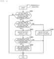
- FIG. 3 is a flowchart showing a state diagnosis for the storage battery 111 executed by the elevator controller 7 according to the present embodiment.
- the elevator controller 7 determines in step S301 that whether a predetermined time t 1 or more is elapsed after when the power supply contact 150 is finally turned off ( FIG. 2 ).
- t 1 can be freely set in consideration of an interval between diagnoses of other elevator apparatuses or the like. For example, t 1 is set to 30 days.
- step S301 When a call is not registered and the car 1 is stopped, that is, when the car 1 is in the standby state, the elevator controller 7 executes step S301.
- step S301 When the elevator controller 7 determines that t 1 or more is elapsed (YES in step S301), next the elevator controller 7 executes step S302, and when the elevator controller 7 determines that t 1 or more is not elapsed (NO in step S301), the elevator controller 7 ends a series of processing.
- step S302 the elevator controller 7 determines whether the standby state continues for a predetermined time t 2 .
- t 2 is freely set in consideration of a standby state continuing time that can be estimated to be an elevator usage situation in which service is not lowered even when the state diagnosis for the storage battery 111 is executed. For example, t 2 is set to 10 minutes.
- step S302 When the elevator controller 7 determines that the standby state continues for t 2 or more (YES in step S302), next the elevator controller 7 executes step S303, and when the elevator controller 7 determines that the standby state does not continue for t 2 or more (NO in step S302), the elevator controller 7 executes step S302 again.
- step S303 the elevator controller 7 cuts off the power supply contact 150. Accordingly, the electromagnets 35a and 35b of the electric actuator 10 are electrically cut off from the DC power supply 300, and are excited by the storage battery 111 only. That is, an excited state of the electromagnets 35a and 35b during power outage is simulated.
- step S303 the elevator controller 7 executes step S304.
- step S304 the elevator controller 7 determines whether the movable element detection switch 109 ( FIG. 2 ) is in an off state.
- the off state of the movable element detection switch 109 indicates that the movable element (34a, 34b, 34c) ( FIG. 2 ) cannot be held at the standby position by the excitation of the electromagnets 35a and 35b by the storage battery 111, and the movable element is moved to the position P shown in FIG. 2 .
- step S305 the elevator controller 7 determines, based on the measured value of the elapsed time, whether a predetermined time t 3 is elapsed after when the power supply contact 150 is cut off.
- the predetermined time t 3 is set in consideration of a time during which the storage battery 111 is required to be able to supply power to the electromagnets 35a and 35b during power outage.
- the time during which power can be supplied is, for example, a time up to when the car is stopped if power outage occurs while the car is traveling at highest speed. For example, t 3 is set to 3 minutes.
- step S305 When the elevator controller 7 determines that the predetermined time t 3 is elapsed (YES in step S305), next the elevator controller 7 executes step S306, and when the elevator controller 7 determines that the predetermined time t 3 is not elapsed (NO in step S305), the elevator controller 7 executes step S304 again.
- step S306 the elevator controller 7 turns on the power supply contact 150. Accordingly, the electromagnets 35a and 35b are excited by the DC power supply 300 regardless of a state of the storage battery 111. After step S306, the elevator controller 7 executes step S307.
- step S307 the elevator controller 7 stores a time during which the power supply contact 150 is cut off (hereinafter referred to as "cut-off time (t) ”) .
- cut-off time (t) a time during which the power supply contact 150 is cut off.
- step S307 the elevator controller 7 executes step S308.
- step S308 the elevator controller 7 determines whether the movable element detection switch 109 is in an off state.
- the elevator controller 7 determines that the movable element detection switch 109 is in the off state (YES in step S308), next, the elevator controller 7 executes step S309.
- step S309 the elevator controller 7 drives the motor 37 provided in the electric actuator 10 to move the electromagnets 35a and 35b, causes the electromagnets 35a and 35b to attract the movable element, and instructs the motor controller 112 to rotate the motor 37 forward and backward so as to return the movable element to the standby position.
- the elevator controller 7 ends the series of processing.
- step S308 determines in step S308 that the movable element detection switch 109 is not in the off state (NO in step S308), that is, when the elevator controller 7 determines that the movable element detection switch 109 is in an on state, since the movable element is positioned at the standby position, the elevator controller 7 skips step S309, and ends the series of processing.
- FIG. 4 is a flowchart showing processing after the state diagnosis for the storage battery 111 executed by the elevator controller according to the present embodiment.
- step S401 the elevator controller 7 determines whether the cut-off time (t) of the power supply contact 150 is less than the predetermined time t 3 .
- the elevator controller 7 determines that the cut-off time (t) is less than the predetermined time t 3 (YES in step S401)
- step S402 the elevator controller 7 executes step S402
- step S402 the elevator controller 7 determines that the cut-off time (t) is not less than the predetermined time t 3 (NO in step S401)
- the elevator controller 7 ends a series of processing since the storage battery 111 is in a normal state.
- step S402 the elevator controller 7 determines whether the cut-off time (t) of the power supply contact 150 is less than a predetermined time t 4 .
- the predetermined time t 4 is shorter than t 3 .
- t 3 is set to 3 minutes
- t 2 is set to 5 seconds.
- t 2 and t 3 are set.
- step S403 When the elevator controller 7 determines that the cut-off time is less than the predetermined time t 2 (YES in step S402), next the elevator controller 7 executes step S403, and when the elevator controller 7 determines that the cut-off time is not less than the predetermined time t 3 (NO in step S402), next the elevator controller 7 executes step S404.
- step S405 the elevator controller 7 determines whether a destination floor in a downward direction from a current position of the car is registered.
- the elevator controller 7 determines that the destination floor is registered (YES in step S405)
- step S406 the elevator controller 7 executes step S406, and when the elevator controller 7 determines that the destination floor is not registered (NO in step S405), the elevator controller 7 ends the series of processing.
- step S406 the elevator controller 7 limits a speed of the car during a lowering operation to a low speed V L .
- V L is set to be lower than a rated speed, and is set to, for example, 60 m/min.
- step S406 the elevator controller 7 ends the series of processing.
- the elevator apparatus including the emergency stop device 2 that is actuated by the electric actuator 10 can have a power outage operation function. Further, maintenance work can be performed quickly and accurately by providing a state diagnosis function for the storage battery 111 that supplies electric power to the electric actuator 10 during power outage. Accordingly, reliability of the power outage operation function of the electric actuator can be maintained.
- the state diagnosis for the storage battery 111 is executed by the elevator controller 7 by cutting off the power supply contact 150 and setting the power supply contact 150 to an on state, stopping the excitation of the electromagnets 35a and 35b by the DC power supply 300, and exciting the electromagnets 35a and 35b by the storage battery 111.
- the elevator controller 7 diagnoses the storage battery 111 as normal when the excitation by the storage battery 111 continues for a predetermined time. At this time, the elevator controller 7 diagnoses the storage battery 111 as normal when the elevator controller 7 determines that the movable element continues to be attracted to the electromagnets 35a and 35b for a predetermined time and the movable element detection switch 109 is maintained in the on state.
- the elevator controller 7 executes the diagnosis by determining a diagnosis execution time and controlling the electric actuator and the power supply contact in the same manner as in the case of power outage.
- the state of the storage battery 111 can be automatically diagnosed without an operation performed by a maintenance engineer.
Landscapes
- Engineering & Computer Science (AREA)
- Mechanical Engineering (AREA)
- Maintenance And Inspection Apparatuses For Elevators (AREA)
- Elevator Control (AREA)
Abstract
Description
- The present invention relates to an elevator apparatus including an emergency stop device that is actuated by an electric actuator.
- An elevator apparatus includes a governor and an emergency stop device to constantly monitor an elevating speed of a car and emergency-stop the car in a predetermined overspeed state. Generally, the car and the governor are coupled to each other by a governor rope. When the overspeed state is detected, the governor restricts the governor rope to operate the emergency stop device on a car side and emergency-stop the car.
- In such an elevator apparatus, since the governor rope which is elongated is laid in a hoistway, it is difficult to save space and reduce cost. Further, when the governor rope swings, a structure in the hoistway is likely to interfere with the governor rope.
- In view of this problem, an emergency stop device that is actuated electrically without using a governor rope is proposed. A technique related to such an emergency stop device in the related art is disclosed in
PTL 1. - In the related art, a car is provided with a drive shaft that drives an emergency stop device, and an electric actuator that actuates the drive shaft. The electric actuator includes a movable iron core mechanically connected to the drive shaft, and an electromagnet that attracts the movable iron core. The drive shaft is biased by a drive spring, but during normal times, movement of the drive shaft is restricted by the electric actuator since the electromagnet is energized and the movable iron core is attracted.
- In an emergency, the electromagnet is demagnetized to release the restriction on the drive shaft, and the drive shaft is driven by a biasing force of the drive spring. As a result, the emergency stop device is actuated to emergency-stop the car.
- When the emergency stop device is returned to a normal state, the electromagnet is moved and brought close to the movable iron core that was moved in an emergency. The electromagnet includes a feed nut that is screwed onto a feed screw shaft. When the feed screw shaft is rotated by a motor, the electromagnet moves toward the movable iron core. When the electromagnet comes into contact with the movable iron core, the movable iron core is attracted to the electromagnet. In a state in which the movable iron core is attracted to the electromagnet, the electromagnet is further moved to return the movable iron core and the electromagnet to a normal standby position.
- PTL 1:
JP2021-130550A - In the related art described above, when a power supply to the electromagnet is lost due to a power outage, the electric actuator is actuated and the emergency stop device is actuated as in a case when an overspeed state is detected. Therefore, it is difficult to operate a car during a power outage or power restoration depending on a state of the electric actuator.
- Therefore, the invention provides an elevator apparatus having a power outage operation function and including an emergency stop device actuated by an electric actuator.
- In order to solve the above problem, an elevator apparatus according to the invention includes a car, an emergency stop device provided at the car, a drive mechanism configured to drive the emergency stop device, an electric actuator configured to actuate the drive mechanism, and a controller configured to control an operation of the car. The electric actuator includes a movable element mechanically connected to the drive mechanism, and an electromagnet facing the movable element. The elevator apparatus further includes a DC power supply connected to the electromagnet via a power supply contact and configured to excite the electromagnet, and a storage battery connected to the electromagnet. The controller cuts off the power supply contact during power outage, and the electromagnet is excited by the storage battery when the power supply contact is cut off.
- According to the invention, the elevator apparatus including the emergency stop device actuated by the electric actuator can have a power outage operation function.
- Problems, configurations, and effects other than those described above will be clarified by the following description of embodiments.
-
- [
FIG. 1] FIG. 1 is a schematic configuration diagram showing an elevator apparatus according to an embodiment. - [
FIG. 2] FIG. 2 is a plan view showing mechanical portions and electrical device portions of an electric actuator according to the present embodiment in an installed state shown inFIG. 1 . - [
FIG. 3] FIG. 3 is a flowchart showing a state diagnosis for a storage battery executed by an elevator controller according to the present embodiment. - [
FIG. 4] FIG. 4 is a flowchart showing processing after the state diagnosis for the storage battery executed by the elevator controller according to the present embodiment. - Hereinafter, an elevator apparatus according to an embodiment of the invention will be described with reference to the drawings. In the drawings, components having the same reference numerals indicate the same components or components having similar functions.
-
FIG. 1 is a schematic configuration diagram showing an elevator apparatus according to an embodiment of the invention. - As shown in
FIG. 1 , the elevator apparatus includes acar 1, speed sensors (5 and 6), anelectric actuator 10, drive mechanisms (12 to 20), pull-up rods 21, andemergency stop devices 2. - The
car 1 is suspended by a main rope (not shown) in a hoistway provided in a building, and is slidably engaged withguide rails 4 via guide devices. When the main rope is frictionally driven by a drive device (hoist: not shown), thecar 1 is moved up and down in the hoistway. - The speed sensor in the present embodiment is provided on the
car 1, and includes arotary detector 6 and aroller 5 connected to a rotation shaft of therotary detector 6. In the present embodiment, theroller 5 is connected to the rotation shaft of therotary detector 6 such that a rotation shaft of theroller 5 and the rotation shaft of therotary detector 6 are coaxial. For example, a rotary encoder can be applied as therotary detector 6. - The
roller 5 is in contact with theguide rail 4. Therefore, theroller 5 rotates when thecar 1 moves up and down, and therotary detector 6 rotates accordingly. A safety controller to be described later monitors a traveling speed of thecar 1 based on a rotational position signal output by therotary detector 6 accompanying the rotation. - An image sensor may be used as the speed sensor. In this case, a position and a speed of the
car 1 are detected based on image information on a surface state of theguide rail 4 acquired by the image sensor. For example, the speed is calculated based on a movement distance of an image feature in a predetermined time. - In the present embodiment, the
electric actuator 10 is an electromagnetic operation device and is disposed on an upper portion of thecar 1. The electromagnetic operation device includes, for example, a movable piece or a movable rod actuated by a solenoid or an electromagnet. Theelectric actuator 10 is actuated when the speed sensors (5, 6) detect a predetermined overspeed state of thecar 1. At this time, the pull-up rod 21 is pulled up by the drive mechanisms (12 to 20) that are mechanically connected to anoperation lever 11. Accordingly, theemergency stop device 2 enters a braking state. - The drive mechanisms (12 to 20) will be described later.
- One
emergency stop device 2 is disposed on each of left and right sides of thecar 1. A pair of braking elements (not shown) provided in eachemergency stop device 2 are movable between a braking position and a non-braking position, and clamp theguide rails 4 in the braking position. When theemergency stop device 2 moves up relative to thecar 1 due to thecar 1 moving down, a braking force is generated by a frictional force acting between the braking elements and theguide rails 4. Accordingly, theemergency stop device 2 is actuated when thecar 1 falls into an overspeed state, and emergency-stops thecar 1. - The elevator apparatus in the present embodiment includes a so-called low-press governor system that does not use a governor rope. When an elevating speed of the
car 1 exceeds a rated speed and reaches a first overspeed (for example, a speed that does not exceed a speed 1.3 times the rated speed), a power supply to the drive device (the hoist) and a power supply to a control device that controls the drive device are cut off. When a descending speed of thecar 1 reaches a second overspeed (for example, a speed that does not exceed a speed 1.4 times the rated speed), theelectric actuator 10 provided on thecar 1 is electrically driven to actuate theemergency stop device 2 and emergency-stop thecar 1. - In the present embodiment, the low-press governor system includes the speed sensors (5, 6) and the safety controller that determines an overspeed state of the
car 1 based on an output signal of the speed sensors. The safety controller measures a speed of thecar 1 based on the output signal of the speed sensors. When the safety controller determines that the measured speed reaches the first overspeed, the safety controller outputs a command signal for cutting off the power supply to the drive device (the hoist) and the power supply to the control device that controls the drive device. When the safety controller determines that the measured speed reaches the second overspeed, the safety controller outputs a command signal for actuating theelectric actuator 10. - As described above, when the pair of braking elements provided in the
emergency stop device 2 are pulled up by the pull-uprods 21, the pair of braking elements clamp theguide rail 4. The pull-uprod 21 is driven by the drive mechanisms (12 to 20) connected to theelectric actuator 10. - Hereinafter, a configuration of the drive mechanisms will be described.
- The
operation lever 11 of theelectric actuator 10 is coupled to afirst actuating piece 16 to form a substantially T-shaped first link member. Theoperation lever 11 and thefirst actuating piece 16 respectively constitute a head portion and a foot portion of a T shape. The substantially T-shaped first link member is pivotably supported by acrosshead 50 via afirst actuating shaft 19 at a coupling portion between theoperation lever 11 and thefirst actuating piece 16. One of a pair of pull-up rods 21 (on a left side in the drawing) has an end portion connected to an end portion of thefirst actuating piece 16 that is the foot portion of the T shape and is located on a side opposite to the coupling portion between theoperation lever 11 and thefirst actuating piece 16. - A
connection piece 17 is coupled to asecond actuating piece 18 to form a substantially T-shaped second link member. Theconnection piece 17 and thesecond actuating piece 18 respectively constitute a head portion and a foot portion of a T shape. The substantially T-shaped second link member is pivotably supported by thecrosshead 50 via asecond actuating shaft 20 at a coupling portion between theconnection piece 17 and thesecond actuating piece 18. The other one of the pair of pull-up rods 21 (on a left side in the drawing) has an end portion connected to an end portion of thesecond actuating piece 18 that is the foot portion of the T shape and is located on a side opposite to the coupling portion between theconnection piece 17 and thesecond actuating piece 18. - An end portion of the
operation lever 11 that extends from inside to outside of acase 30 and one of two end portions of theconnection piece 17 that is closer to an upper portion of thecar 1 than thesecond actuating shaft 20 are respectively connected to one end (on the left side in the drawing) and the other end (on the right side in the drawing) of adrive shaft 12 lying transversely on thecar 1. Thedrive shaft 12 slidably passes through a fixedportion 14 fixed to thecrosshead 50. Thedrive shaft 12 passes through a pressingmember 15, and the pressingmember 15 is fixed to thedrive shaft 12. The pressingmember 15 is located on a side closer to the second link member (theconnection piece 17 and the second actuating piece 18) than the fixedportion 14. Adrive spring 13 that is an elastic body is located between the fixedportion 14 and the pressingmember 15, and thedrive shaft 12 is inserted through thedrive spring 13. - When the
electric actuator 10 is actuated, that is, when energization to an electromagnet is cut off in the present embodiment, an electromagnetic force that restricts movement of theoperation lever 11 against a biasing force of thedrive spring 13 disappears. Accordingly, thedrive shaft 12 is driven along a longitudinal direction by the biasing force of thedrive spring 13 applied to the pressingmember 15. Therefore, the first link member (theoperation lever 11 and the first actuating piece 16) pivots about thefirst actuating shaft 19, and the second link member (theconnection piece 17 and the second actuating piece 18) pivots about thesecond actuating shaft 20. Accordingly, one of the pull-uprods 21 connected to thefirst actuating piece 16 of the first link member is driven and pulled up, and the other pull-uprod 21 connected to thesecond actuating piece 18 of the second link member is driven and pulled up at the same time. -
FIG. 2 is a plan view showing mechanical portions and electrical device portions of theelectric actuator 10 according to the present embodiment in an installed state shown inFIG. 1 . Theelectric actuator 10 shown inFIG. 2 is stored in thecase 30 shown inFIG. 1 (the same applies toFIGS. 3 and4 ). -
FIG. 2 also shows a circuit configuration for controlling the electrical device portions (the same applies toFIGS. 3 and4 ). InFIG. 2 , the emergency stop devices 2 (FIG. 1 ) are in a non-braking state, and theelectric actuator 10 is in a standby state. That is, the elevator apparatus is in a normal operation state. - As shown in
FIG. 2 , in the standby state, a movable element (34a, 34b, 34c) that is a movable member connected to theoperation lever 11 is attracted by electromagnetic forces toelectromagnets FIG. 1 ) acting on the movable element via the drive shaft 12 (FIG. 1 ) and theoperation lever 11. Accordingly, theelectric actuator 10 restricts movement of the drive mechanisms (12 to 20:FIG. 1 ) against the biasing force of thedrive spring 13. - The movable element includes an
attraction portion 34a that is attracted to pole surfaces of theelectromagnets support portion 34b that is fixed to theattraction portion 34a and to which theoperation lever 11 is connected. Theoperation lever 11 is pivotably connected to thesupport portion 34b of the movable element via aconnection bracket 38. Theelectric actuator 10 is provided with a movableelement detection switch 109 at a position where theattraction portion 34a of the movable element is located during standby. - The movable element further includes a
cam portion 34c fixed to theattraction portion 34a. When the movable element is located at a standby position, the movableelement detection switch 109 is operated by thecam portion 34c. When the movableelement detection switch 109 is operated by thecam portion 34c, the movableelement detection switch 109 transitions from an on state to an off state or from the off state to the on state. Accordingly, it is possible to detect whether the movable element is located at the standby position according to a state of the movableelement detection switch 109. - In the present embodiment, the movable
element detection switch 109 is in the on state when the movableelement detection switch 109 is operated by thecam portion 34c. - In the movable element (34a, 34b, 34c) according to the present embodiment, at least the
attraction portion 34a is made of a magnetic material. A soft magnetic material such as low-carbon steel and permalloy (iron-nickel alloy) is preferably used as the magnetic material. - Other mechanism units (36, 37, 39, 41) shown in
FIG. 2 will be described later. - The
electromagnets DC power supply 300 and astorage battery 111. TheDC power supply 300 includes a rectifier or a power converter that converts AC power input from a commercialAC power supply 200 into DC power. A DC output of theDC power supply 300 is connected in parallel to thestorage battery 111 via apower supply contact 150. Thepower supply contact 150 is implemented by a contact provided in, for example, an electromagnetic relay, an electromagnetic contactor, and an electromagnetic switch. - When AC power is supplied from the commercial
AC power supply 200, mainly theelectromagnets DC power supply 300. At this time, anelevator controller 7 controls thepower supply contact 150 to be in a closed state. Accordingly, theDC power supply 300 excites theelectromagnets storage battery 111. - When the commercial
AC power supply 200 fails, theelectromagnets storage battery 111. At this time, theelevator controller 7 controls thepower supply contact 150 to be in an on state. Accordingly, a discharge current from thestorage battery 111 is prevented from flowing to theDC power supply 300 side. As will be described later, thepower supply contact 150 is also controlled by theelevator controller 7 when theelevator controller 7 executes a state diagnosis for thestorage battery 111. - In an excitation circuit of the
electromagnet 35a, one end of a coil of theelectromagnet 35a is connected to a high potential side of thestorage battery 111 viaelectrical contacts fuse 107a that are connected in series, and is further connected to a high potential side of the DC output of theDC power supply 300 via thepower supply contact 150. The other end of the coil of theelectromagnet 35a is connected to a low potential side of thestorage battery 111 and a low potential side of the DC power supply. - In an excitation circuit of the
electromagnet 35b, one end of a coil of theelectromagnet 35b is connected to a high potential side of thestorage battery 111 viaelectrical contacts fuse 107b that are connected in series, and is further connected to a high potential side of the DC output of theDC power supply 300 via thepower supply contact 150. The other end of the coil of theelectromagnet 35b is connected to a low potential side of thestorage battery 111 and a low potential side of the DC power supply. - The
fuses electromagnets - The
electrical contacts safety controller 103. In the standby state of theelectric actuator 10, thesafety controller 103 controls theelectrical contacts electromagnets electromagnets - Each of the
electrical contacts electromagnets FIG. 2 ) electrical contacts are connected in series. Accordingly, even when an on failure occurs in one contact when the plurality of electrical contacts are controlled to be in an off state to actuate theemergency stop device 2 as will be described later, energization of the electromagnet is cut off. Accordingly, operation reliability of theelectric actuator 10 is improved. The on failure occurs due to, for example, welding of a contact. - Other electrical device portions (37, 112) will be described later.
Signal lines electromagnets safety controller 103. - An answer back signal (hereinafter referred to as an "answer back signal (106a)") input to the
safety controller 103 via thesignal line 106a indicates a potential of one of the two ends of the coil of theelectromagnet 35a which is connected to the high potential side of thestorage battery 111 and the high potential side of theDC power supply 300 via theelectrical contacts storage battery 111 and the high potential side of theDC power supply 300 when theelectromagnet 35a is energized, and indicates a potential (a low potential (LOW)) on the low potential side of thestorage battery 111 and the low potential side of theDC power supply 300 when theelectromagnet 35a is not energized. Thesafety controller 103 detects an energization state of theelectromagnet 35a based on a potential indicated by the answer back signal (106a). - The answer back signal (hereinafter referred to as an "answer back signal (106b)") input to the
safety controller 103 via thesignal line 106b indicates a potential of one of the two ends of the coil of theelectromagnet 35b which is connected to the high potential side of thestorage battery 111 and the high potential side of theDC power supply 300 via theelectrical contacts storage battery 111 and theDC power supply 300 when theelectromagnet 35b is energized, and indicates a potential (a low potential (LOW)) on the low potential side of thestorage battery 111 and the low potential side of theDC power supply 300 when theelectromagnet 35b is not energized. Thesafety controller 103 detects an energization state of theelectromagnet 35b based on a potential indicated by the answer back signal (106b). - Next, an operation of the
electric actuator 10 when theemergency stop device 2 is actuated will be described. - When the
safety controller 103 detects a predetermined overspeed state (the above-described second overspeed) of thecar 1 based on a rotational position signal from therotary detector 6, thesafety controller 103 outputs an off command to each of theelectrical contacts electrical contacts FIG. 2 ) to an off state. Therefore, excitation of theelectromagnets attraction portion 34a of the movable element to theelectromagnets FIG. 2 ) of thedrive spring 13, from a position (FIG. 2 ) in the standby state to a position P in a direction (a rightward direction in the drawing) of the biasing force of thedrive spring 13. InFIG. 2 , the moved movable element is indicated by a two-dot chain line. - As the restriction on the movable element is released, the
drive shaft 12 is driven by the biasing force of the drive spring 13 (FIG. 1 ) acting on the pressing member 15 (FIG. 1 ) of thedrive shaft 12 in a direction from the fixed portion 14 (FIG. 1 ) toward the pressing member (FIG. 1 ). When thedrive shaft 12 is driven, the first link member (theoperation lever 11 and the first actuating piece 16:FIG. 1 ) connected to thedrive shaft 12 pivots about the first actuating shaft 19 (FIG. 1 ). Accordingly, the pull-up rod 21 (FIG. 1 ) connected to thefirst actuating piece 16 is pulled up. When thedrive shaft 12 is driven, the second link member (theconnection piece 17 and the second actuating piece 18:FIG. 1 ) connected to thedrive shaft 12 pivots about the second actuating shaft 20 (FIG. 1 ). Accordingly, the pull-up rod 21 (FIG. 1 ) connected to thesecond actuating piece 18 is pulled up. - Next, a return operation of the
electric actuator 10 will be described. - To return the
electric actuator 10 to the standby state from an actuated state, as will be described later, the movable element (34a, 34b, 34c) is returned to a standby position from a moved position (the position P inFIG. 2 ) by the return mechanism units (36, 37, 39, and 41) and the electrical device portions (37 and 112). - The
electric actuator 10 includes afeed screw 36 for driving the movable element. Thefeed screw 36 is coaxially connected to a rotation shaft of amotor 37 and is rotatably supported by asupport member 41. Theelectromagnets electromagnet support plate 39 including a feed nut portion (not shown). The feed nut portion of theelectromagnet support plate 39 is screwed with thefeed screw 36. Thefeed screw 36 is rotated by themotor 37. Themotor 37 is driven by amotor controller 112. - The
motor controller 112 includes a drive circuit for themotor 37, and controls rotation of themotor 37 according to a control command from theelevator controller 7. Themotor 37 may be either a DC motor or an AC motor. - The
elevator controller 7 controls a normal operation of thecar 1 and has information on an operation state of thecar 1. In the present embodiment, as described above, theelevator controller 7 further has a function of controlling themotor 37 provided in theelectric actuator 10. - When the
electric actuator 10 is returned to the standby state, theelevator controller 7 sends a rotation command for themotor 37 to themotor controller 112. Upon receiving the rotation command, themotor controller 112 drives themotor 37 to rotate thefeed screw 36. The rotation of themotor 37 is converted into linear movement of theelectromagnets feed screw 36 by therotating feed screw 36 and the feed nut portion of theelectromagnet support plate 39. Accordingly, theelectromagnets - The
motor controller 112 monitors a motor current for controlling themotor 37. When theelectromagnets motor 37 increases, and the motor current increases accordingly. When the motor current increases and exceeds a predetermined value, themotor controller 112 determines that theelectromagnets motor controller 112 sends a determination result to thesafety controller 103 and theelevator controller 7. - Upon receiving the determination result from the
motor controller 112, thesafety controller 103 outputs an on command to each of theelectrical contacts electrical contacts electromagnets attraction portion 34a of the movable element is attracted to theelectromagnets excited electromagnets - Upon receiving the determination result from the
motor controller 112, theelevator controller 7 sends a reverse rotation command for themotor 37 to themotor controller 112. Upon receiving the reverse rotation command, themotor controller 112 reverses a rotation direction of themotor 37 and rotates thefeed screw 36 in a reverse direction. Accordingly, the movable element attracted to theelectromagnets drive spring 13, and moves toward the standby position together with theelectromagnets - The
cam portion 34c of the movable element (34a, 34b, 34c) is separated from the movableelement detection switch 109 from when theelectric actuator 10 is actuated and the movable element (34a, 34b, 34c) is moved to the position P (FIG. 3 ) up to immediately before the completion of the return operation of theelectric actuator 10. Accordingly, the movableelement detection switch 109 is in an off state at this time. - When the movable element (34a, 34b, 34c) attracted to the
electromagnets element detection switch 109 is operated by thecam portion 34c of the movable element. When the movableelement detection switch 109 is operated, theelevator controller 7 determines that the movable element is located at the standby position. Theelevator controller 7 sends a stop command for themotor 37 to themotor controller 112 based on this determination result. Upon receiving the stop command, themotor controller 112 stops the rotation of themotor 37. - As will be described later, the state diagnosis for the
storage battery 111 is executed by theelevator controller 7 when the elevator apparatus is in operation, when no call is registered, and when thecar 1 is in a standby state where thecar 1 is stopped at the first floor. Theelevator controller 7 sets thepower supply contact 150 to be in an on state, stops the excitation of theelectromagnets DC power supply 300, and excites theelectromagnets storage battery 111. Theelevator controller 7 diagnoses thestorage battery 111 as normal when the excitation by thestorage battery 111 continues for a predetermined time. At this time, theelevator controller 7 diagnoses thestorage battery 111 as normal when theelevator controller 7 determines that the movable element continues to be attracted to theelectromagnets element detection switch 109 is maintained in the on state. -
FIG. 3 is a flowchart showing a state diagnosis for thestorage battery 111 executed by theelevator controller 7 according to the present embodiment. - When the processing is started, first, the
elevator controller 7 determines in step S301 that whether a predetermined time t1 or more is elapsed after when thepower supply contact 150 is finally turned off (FIG. 2 ). t1 can be freely set in consideration of an interval between diagnoses of other elevator apparatuses or the like. For example, t1 is set to 30 days. - When a call is not registered and the
car 1 is stopped, that is, when thecar 1 is in the standby state, theelevator controller 7 executes step S301. - When the
elevator controller 7 determines that t1 or more is elapsed (YES in step S301), next theelevator controller 7 executes step S302, and when theelevator controller 7 determines that t1 or more is not elapsed (NO in step S301), theelevator controller 7 ends a series of processing. - In step S302, the
elevator controller 7 determines whether the standby state continues for a predetermined time t2. t2 is freely set in consideration of a standby state continuing time that can be estimated to be an elevator usage situation in which service is not lowered even when the state diagnosis for thestorage battery 111 is executed. For example, t2 is set to 10 minutes. - When the
elevator controller 7 determines that the standby state continues for t2 or more (YES in step S302), next theelevator controller 7 executes step S303, and when theelevator controller 7 determines that the standby state does not continue for t2 or more (NO in step S302), theelevator controller 7 executes step S302 again. - In step S303, the
elevator controller 7 cuts off thepower supply contact 150. Accordingly, theelectromagnets electric actuator 10 are electrically cut off from theDC power supply 300, and are excited by thestorage battery 111 only. That is, an excited state of theelectromagnets elevator controller 7 executes step S304. - In step S304, the
elevator controller 7 determines whether the movable element detection switch 109 (FIG. 2 ) is in an off state. The off state of the movableelement detection switch 109 indicates that the movable element (34a, 34b, 34c) (FIG. 2 ) cannot be held at the standby position by the excitation of theelectromagnets storage battery 111, and the movable element is moved to the position P shown inFIG. 2 . - When the
elevator controller 7 determines that the movableelement detection switch 109 is in the off state (YES in step S304), next theelevator controller 7 executes step S306, and when theelevator controller 7 determines that the movableelement detection switch 109 is not in the off state (NO in step S304), that is, when theelevator controller 7 determines that the movableelement detection switch 109 is in an on state, theelevator controller 7 measures an elapsed time (initial value = 0) after a time point when thepower supply contact 150 is cut off (step 303), and next theelevator controller 7 executes step S305. - In step S305, the
elevator controller 7 determines, based on the measured value of the elapsed time, whether a predetermined time t3 is elapsed after when thepower supply contact 150 is cut off. The predetermined time t3 is set in consideration of a time during which thestorage battery 111 is required to be able to supply power to theelectromagnets - When the
elevator controller 7 determines that the predetermined time t3 is elapsed (YES in step S305), next theelevator controller 7 executes step S306, and when theelevator controller 7 determines that the predetermined time t3 is not elapsed (NO in step S305), theelevator controller 7 executes step S304 again. - In step S306, the
elevator controller 7 turns on thepower supply contact 150. Accordingly, theelectromagnets DC power supply 300 regardless of a state of thestorage battery 111. After step S306, theelevator controller 7 executes step S307. - In step S307, the
elevator controller 7 stores a time during which thepower supply contact 150 is cut off (hereinafter referred to as "cut-off time (t) ") . As described above, in step S304, when theelevator controller 7 determines that the movableelement detection switch 109 is not in the off state (NO in step S304), that is, when theelevator controller 7 determines that the movableelement detection switch 109 is in the on state, theelevator controller 7 measures the elapsed time (initial value = 0) after the time point when thepower supply contact 150 is cut off (step S303). The measured value of the elapsed time is stored as the cut-off time (t). - After step S307, the
elevator controller 7 executes step S308. - In step S308, the
elevator controller 7 determines whether the movableelement detection switch 109 is in an off state. When theelevator controller 7 determines that the movableelement detection switch 109 is in the off state (YES in step S308), next, theelevator controller 7 executes step S309. - In step S309, the
elevator controller 7 drives themotor 37 provided in theelectric actuator 10 to move theelectromagnets electromagnets motor controller 112 to rotate themotor 37 forward and backward so as to return the movable element to the standby position. After step S309, theelevator controller 7 ends the series of processing. - When the
elevator controller 7 determines in step S308 that the movableelement detection switch 109 is not in the off state (NO in step S308), that is, when theelevator controller 7 determines that the movableelement detection switch 109 is in an on state, since the movable element is positioned at the standby position, theelevator controller 7 skips step S309, and ends the series of processing. -
FIG. 4 is a flowchart showing processing after the state diagnosis for thestorage battery 111 executed by the elevator controller according to the present embodiment. - In step S401, the
elevator controller 7 determines whether the cut-off time (t) of thepower supply contact 150 is less than the predetermined time t3. When theelevator controller 7 determines that the cut-off time (t) is less than the predetermined time t3 (YES in step S401), next theelevator controller 7 executes step S402, and when theelevator controller 7 determines that the cut-off time (t) is not less than the predetermined time t3 (NO in step S401), theelevator controller 7 ends a series of processing since thestorage battery 111 is in a normal state. - In step S402, the
elevator controller 7 determines whether the cut-off time (t) of thepower supply contact 150 is less than a predetermined time t4. Here, the predetermined time t4 is shorter than t3. For example, t3 is set to 3 minutes, and t2 is set to 5 seconds. In order to distinguish a level of an abnormal state of thestorage battery 111, t2 and t3 are set. - When the
elevator controller 7 determines that the cut-off time is less than the predetermined time t2 (YES in step S402), next theelevator controller 7 executes step S403, and when theelevator controller 7 determines that the cut-off time is not less than the predetermined time t3 (NO in step S402), next theelevator controller 7 executes step S404. - In step S403, since the cut-off time is less than t4, the
elevator controller 7 determines that a battery capacity is lost, and reports the battery capacity loss to an external party such as a maintenance engineer and a maintenance company. After step S403, theelevator controller 7 executes step S405. - In step S404, since the cut-off time (t) is not less than t4 but is relatively short as less than t3 (t2 ≤ t < t3), the
elevator controller 7 determines that the battery capacity decreases, and reports the decrease in the battery capacity to an external party such as a maintenance engineer or a maintenance company. After step S404, theelevator controller 7 ends the series of processing. - In step S405, the
elevator controller 7 determines whether a destination floor in a downward direction from a current position of the car is registered. When theelevator controller 7 determines that the destination floor is registered (YES in step S405), next theelevator controller 7 executes step S406, and when theelevator controller 7 determines that the destination floor is not registered (NO in step S405), theelevator controller 7 ends the series of processing. - In step S406, the
elevator controller 7 limits a speed of the car during a lowering operation to a low speed VL. VL is set to be lower than a rated speed, and is set to, for example, 60 m/min. - Here, a low-speed lowering operation is possible, and even when the emergency stop device is operated,
after step S406, theelevator controller 7 ends the series of processing. - According to the present embodiment described above, the elevator apparatus including the
emergency stop device 2 that is actuated by theelectric actuator 10 can have a power outage operation function. Further, maintenance work can be performed quickly and accurately by providing a state diagnosis function for thestorage battery 111 that supplies electric power to theelectric actuator 10 during power outage. Accordingly, reliability of the power outage operation function of the electric actuator can be maintained. - According to the embodiment described above, the state diagnosis for the
storage battery 111 is executed by theelevator controller 7 by cutting off thepower supply contact 150 and setting thepower supply contact 150 to an on state, stopping the excitation of theelectromagnets DC power supply 300, and exciting theelectromagnets storage battery 111. Theelevator controller 7 diagnoses thestorage battery 111 as normal when the excitation by thestorage battery 111 continues for a predetermined time. At this time, theelevator controller 7 diagnoses thestorage battery 111 as normal when theelevator controller 7 determines that the movable element continues to be attracted to theelectromagnets element detection switch 109 is maintained in the on state. - As described above, similar to the case of power outage, electric power is supplied from the
storage battery 111 to theelectric actuator 10, and the electric actuator is maintained in the standby state in the present embodiment. That is, a position of the movable element of the electric actuator is held at the standby position. A state of thestorage battery 111 is diagnosed according to a time during which the movable element can be held. Accordingly, according to the present embodiment, it is possible to diagnose with high accuracy whether thestorage battery 111 is maintained in an appropriate state by the power outage operation function of theelectric actuator 10. - Further, the
elevator controller 7 executes the diagnosis by determining a diagnosis execution time and controlling the electric actuator and the power supply contact in the same manner as in the case of power outage. When the elevator apparatus is in operation, the state of thestorage battery 111 can be automatically diagnosed without an operation performed by a maintenance engineer. - The invention is not limited to the above-described embodiment, and includes various modifications. For example, the embodiment described above is described in detail to facilitate understanding of the invention, and the invention is not necessarily limited to those including all configurations described above. One configuration in the embodiment can be added to, deleted from, or replaced with another configuration.
- For example, instead of the movable
element detection switch 109, another position detection sensor such as a photoelectric position sensor, a magnetic position sensor, and a proximity sensor (capacitive or inductive) may be applied. - The
electric actuator 10 may be provided at a lower portion or a side portion of thecar 1, in addition to an upper portion. - The elevator apparatus may further include a machine room or may be a so-called machine room-less elevator having no machine room.
-
- 1: car
- 2: emergency stop device
- 4: guide rail
- 5: roller
- 6: rotary detector
- 7: elevator controller
- 10: electric actuator
- 11: operation lever
- 12: drive shaft
- 13: drive spring
- 14: fixed portion
- 15: pressing member
- 16: first actuating piece
- 17: connection piece
- 18: second actuating piece
- 19: first actuating shaft
- 20: second actuating shaft
- 21: pull-up rod
- 30: case
- 34a: attraction portion
- 34b: support portion
- 34c: cam portion
- 35a, 35b: electromagnet
- 36: feed screw
- 37: motor
- 38: connection bracket
- 39: electromagnet support plate
- 41: support member
- 50: crosshead
- 103: safety controller
- 104a, 105a, 104b, 105b: electrical contact
- 106a, 106b: signal line
- 107a, 107b: fuse
- 109: movable element detection switch
- 111: storage battery
- 112: motor controller
- 150: power supply contact
- 200: commercial AC power supply
- 300: DC power supply
Claims (7)
- An elevator apparatus comprising:a car;an emergency stop device provided at the car;a drive mechanism configured to drive the emergency stop device;an electric actuator configured to actuate the drive mechanism; anda controller configured to control an operation of the car, whereinthe electric actuator includesa movable element mechanically connected to the drive mechanism, andan electromagnet facing the movable element,the elevator apparatus further comprising:a DC power supply connected to the electromagnet via a power supply contact and configured to excite the electromagnet; anda storage battery connected to the electromagnet,the controller cuts off the power supply contact during power outage, and the electromagnet is excited by the storage battery when the power supply contact is cut off.
- The elevator apparatus according to claim 1, wherein
when the controller diagnoses a state of the storage battery, the controller cuts off the power supply contact, measures a time during which a position of the movable element is held at a standby position, and diagnoses the state of the storage battery based on the measured time. - The elevator apparatus according to claim 2, whereinthe electric actuator includes a position detector configured to detect the movable element located at the standby position, andthe controller measures a time during which the position detector detects the movable element after the power supply contact is cut off, thereby measuring a time during which the position of the movable element is held at the standby position.
- The elevator apparatus according to claim 2, whereinthe controller turns on the power supply contact after measuring the time during which the position of the movable element is held at the standby position, andthe electromagnet is excited by the DC power supply.
- The elevator apparatus according to claim 3, whereinthe electric actuator includes a return mechanism configured to return, to the standby position, the movable element that was moved from the standby position,the controller turns on the power supply contact after measuring the time during which the position of the movable element is held at the standby position,the electromagnet is excited by the DC power supply, andthe return mechanism returns the movable element to the standby position when the position detector does not detect the movable element.
- The elevator apparatus according to claim 1, wherein
the controller determines a time for diagnosing a state of the storage battery, and diagnoses the state of the storage battery in a standby state of the car after the time is determined. - The elevator apparatus according to claim 1, wherein
when the controller determines that a diagnosed state of the power storage battery is a capacity loss state, the controller sets a speed of the car during a lowering operation to a speed lower than a rated speed.
Applications Claiming Priority (1)
| Application Number | Priority Date | Filing Date | Title |
|---|---|---|---|
| PCT/JP2022/025988 WO2024004086A1 (en) | 2022-06-29 | 2022-06-29 | Elevator device |
Publications (2)
| Publication Number | Publication Date |
|---|---|
| EP4549359A1 true EP4549359A1 (en) | 2025-05-07 |
| EP4549359A4 EP4549359A4 (en) | 2026-04-01 |
Family
ID=89382247
Family Applications (1)
| Application Number | Title | Priority Date | Filing Date |
|---|---|---|---|
| EP22949361.4A Pending EP4549359A4 (en) | 2022-06-29 | 2022-06-29 | ELEVATOR DEVICE |
Country Status (4)
| Country | Link |
|---|---|
| EP (1) | EP4549359A4 (en) |
| JP (1) | JPWO2024004086A1 (en) |
| CN (1) | CN119451906A (en) |
| WO (1) | WO2024004086A1 (en) |
Family Cites Families (7)
| Publication number | Priority date | Publication date | Assignee | Title |
|---|---|---|---|---|
| JPS6050706B2 (en) * | 1977-08-17 | 1985-11-09 | 三菱電機株式会社 | Automatic landing device in case of elevator power outage |
| JPH063974U (en) * | 1992-06-17 | 1994-01-18 | 三和テッキ株式会社 | Elevator for narrow vertical passage |
| US6827182B2 (en) * | 2001-10-17 | 2004-12-07 | Mitsubishi Denki Kabushiki Kaisha | Elevator controller |
| JP2018167920A (en) * | 2017-03-29 | 2018-11-01 | 株式会社日立ビルシステム | Elevator blackout time landing driving device |
| JP7280709B2 (en) * | 2019-02-20 | 2023-05-24 | 株式会社日立製作所 | Elevator and elevator control method |
| WO2021166144A1 (en) * | 2020-02-20 | 2021-08-26 | 株式会社日立製作所 | Elevator device |
| JP7292230B2 (en) * | 2020-02-20 | 2023-06-16 | 株式会社日立製作所 | Emergency stop device and elevator |
-
2022
- 2022-06-29 WO PCT/JP2022/025988 patent/WO2024004086A1/en not_active Ceased
- 2022-06-29 EP EP22949361.4A patent/EP4549359A4/en active Pending
- 2022-06-29 JP JP2024530162A patent/JPWO2024004086A1/ja active Pending
- 2022-06-29 CN CN202280097243.4A patent/CN119451906A/en active Pending
Also Published As
| Publication number | Publication date |
|---|---|
| JPWO2024004086A1 (en) | 2024-01-04 |
| WO2024004086A1 (en) | 2024-01-04 |
| EP4549359A4 (en) | 2026-04-01 |
| CN119451906A (en) | 2025-02-14 |
Similar Documents
| Publication | Publication Date | Title |
|---|---|---|
| US12546835B2 (en) | Failure detection device and failure detection method for electric actuator for emergency stop device | |
| JP7212201B2 (en) | elevator equipment | |
| CN100455501C (en) | elevator safety device | |
| EP4414308A1 (en) | Device and method for checking operation of electrically - powered actuator for emergency stop apparatus | |
| CN115720567B (en) | Elevator installation | |
| JP4292202B2 (en) | Actuator operation inspection method and actuator operation inspection apparatus | |
| JP4712696B2 (en) | Elevator control device | |
| US12492101B2 (en) | Elevator apparatus | |
| WO2005092768A1 (en) | Actuator driving method and actuator driving circuit | |
| JP5079326B2 (en) | Elevator control device | |
| WO2023047561A1 (en) | Elevator device | |
| CN120239680A (en) | Elevator device | |
| JP7575623B2 (en) | Inspection device for electric actuators for emergency stop devices | |
| CN111646335A (en) | Method for controlling an elevator | |
| CN119451906A (en) | Elevator device | |
| WO2025120747A1 (en) | Elevator device and control method for elevator device | |
| WO2024252606A1 (en) | Elevator apparatus | |
| WO2025238800A1 (en) | Elevator apparatus and elevator apparatus control method | |
| WO2025120740A1 (en) | Elevator device and control method for elevator device | |
| WO2025115097A1 (en) | Elevator apparatus and elevator control method | |
| CN117794838B (en) | elevator equipment | |
| CN117177932A (en) | elevator installation | |
| JP2025104878A (en) | Elevator safety system and elevator |
Legal Events
| Date | Code | Title | Description |
|---|---|---|---|
| STAA | Information on the status of an ep patent application or granted ep patent |
Free format text: STATUS: THE INTERNATIONAL PUBLICATION HAS BEEN MADE |
|
| PUAI | Public reference made under article 153(3) epc to a published international application that has entered the european phase |
Free format text: ORIGINAL CODE: 0009012 |
|
| STAA | Information on the status of an ep patent application or granted ep patent |
Free format text: STATUS: REQUEST FOR EXAMINATION WAS MADE |
|
| 17P | Request for examination filed |
Effective date: 20250129 |
|
| AK | Designated contracting states |
Kind code of ref document: A1 Designated state(s): AL AT BE BG CH CY CZ DE DK EE ES FI FR GB GR HR HU IE IS IT LI LT LU LV MC MK MT NL NO PL PT RO RS SE SI SK SM TR |
|
| DAV | Request for validation of the european patent (deleted) | ||
| DAX | Request for extension of the european patent (deleted) | ||
| A4 | Supplementary search report drawn up and despatched |
Effective date: 20260304 |
|
| RIC1 | Information provided on ipc code assigned before grant |
Ipc: B66B 5/16 20060101AFI20260226BHEP Ipc: B66B 5/18 20060101ALI20260226BHEP Ipc: B66B 5/02 20060101ALI20260226BHEP |