EP4549351A1 - System for feeding web material, manipulator head for system for feeding web material and method for feeding web material - Google Patents
System for feeding web material, manipulator head for system for feeding web material and method for feeding web material Download PDFInfo
- Publication number
- EP4549351A1 EP4549351A1 EP23206752.0A EP23206752A EP4549351A1 EP 4549351 A1 EP4549351 A1 EP 4549351A1 EP 23206752 A EP23206752 A EP 23206752A EP 4549351 A1 EP4549351 A1 EP 4549351A1
- Authority
- EP
- European Patent Office
- Prior art keywords
- web material
- bobbin
- head
- new
- manipulator
- Prior art date
- Legal status (The legal status is an assumption and is not a legal conclusion. Google has not performed a legal analysis and makes no representation as to the accuracy of the status listed.)
- Pending
Links
Images






Classifications
-
- B—PERFORMING OPERATIONS; TRANSPORTING
- B65—CONVEYING; PACKING; STORING; HANDLING THIN OR FILAMENTARY MATERIAL
- B65H—HANDLING THIN OR FILAMENTARY MATERIAL, e.g. SHEETS, WEBS, CABLES
- B65H19/00—Changing the web roll
- B65H19/10—Changing the web roll in unwinding mechanisms or in connection with unwinding operations
- B65H19/12—Lifting, transporting, or inserting the web roll; Removing empty core
- B65H19/123—Lifting, transporting, or inserting the web roll; Removing empty core with cantilever supporting arrangements
-
- B—PERFORMING OPERATIONS; TRANSPORTING
- B65—CONVEYING; PACKING; STORING; HANDLING THIN OR FILAMENTARY MATERIAL
- B65H—HANDLING THIN OR FILAMENTARY MATERIAL, e.g. SHEETS, WEBS, CABLES
- B65H2301/00—Handling processes for sheets or webs
- B65H2301/40—Type of handling process
- B65H2301/41—Winding, unwinding
- B65H2301/417—Handling or changing web rolls
- B65H2301/418—Changing web roll
- B65H2301/4185—Core or mandrel discharge or removal, also organisation of core removal
- B65H2301/41858—Core or mandrel discharge or removal, also organisation of core removal by collecting cores in container
-
- B—PERFORMING OPERATIONS; TRANSPORTING
- B65—CONVEYING; PACKING; STORING; HANDLING THIN OR FILAMENTARY MATERIAL
- B65H—HANDLING THIN OR FILAMENTARY MATERIAL, e.g. SHEETS, WEBS, CABLES
- B65H2301/00—Handling processes for sheets or webs
- B65H2301/50—Auxiliary process performed during handling process
- B65H2301/54—Auxiliary process performed during handling process for managing processing of handled material
- B65H2301/543—Auxiliary process performed during handling process for managing processing of handled material processing waste material
-
- B—PERFORMING OPERATIONS; TRANSPORTING
- B65—CONVEYING; PACKING; STORING; HANDLING THIN OR FILAMENTARY MATERIAL
- B65H—HANDLING THIN OR FILAMENTARY MATERIAL, e.g. SHEETS, WEBS, CABLES
- B65H2553/00—Sensing or detecting means
-
- B—PERFORMING OPERATIONS; TRANSPORTING
- B65—CONVEYING; PACKING; STORING; HANDLING THIN OR FILAMENTARY MATERIAL
- B65H—HANDLING THIN OR FILAMENTARY MATERIAL, e.g. SHEETS, WEBS, CABLES
- B65H2553/00—Sensing or detecting means
- B65H2553/40—Sensing or detecting means using optical, e.g. photographic, elements
- B65H2553/42—Cameras
-
- B—PERFORMING OPERATIONS; TRANSPORTING
- B65—CONVEYING; PACKING; STORING; HANDLING THIN OR FILAMENTARY MATERIAL
- B65H—HANDLING THIN OR FILAMENTARY MATERIAL, e.g. SHEETS, WEBS, CABLES
- B65H2701/00—Handled material; Storage means
- B65H2701/10—Handled articles or webs
- B65H2701/13—Parts concerned of the handled material
- B65H2701/131—Edges
- B65H2701/1311—Edges leading edge
-
- B—PERFORMING OPERATIONS; TRANSPORTING
- B65—CONVEYING; PACKING; STORING; HANDLING THIN OR FILAMENTARY MATERIAL
- B65H—HANDLING THIN OR FILAMENTARY MATERIAL, e.g. SHEETS, WEBS, CABLES
- B65H2801/00—Application field
- B65H2801/54—Cigarette making
Definitions
- the object of the invention is a system for feeding web material, a manipulator head for a system for feeding web material and a method for feeding web material.
- a web of wrapping material can be fed for an entire product or semi-finished product, for example to wrap a filler material, to wrap the mouthpiece of a finished product or to partially wrap a semi-finished product.
- Unwinding apparatuses adapted to splice successive web materials in order to maintain uninterrupted production are known.
- the document EP1256538 A2 discloses a system and method of feeding a tobacco industry material to an operating unit.
- the system comprises a feeding unit for feeding the material (for example in the form of a bobbin) laid flat on a support to a corresponding unwinding pin of the feeding unit.
- the bobbin is unwound on an unwinding mandrel mounted on the circumference of a rotatable platform rotating around a horizontal axis.
- the system allows the position of the unwinding mandrel to be changed to a vertical receiving position by changing the position of the rotating platform.
- the publication WO02092483 A1 discloses a method of feeding a bobbin from a bobbin storage and an apparatus for feeding the bobbin.
- the apparatus comprises a manipulator with a gripping element for carrying the bobbin from the bobbin storage and for manipulating the bobbins.
- the manipulator has an articulated arm attached to the frame for rotating the bobbin around a vertical axis.
- the gripping element is provided with a distance sensor which allows the gripping element to be correctly positioned in a hole in the bobbin so that the bobbin can be correctly carried onto an unwinding unit.
- the application US9670021 B2 discloses an unwinding station for unwinding a web material rolled into a roll for the manufacture of nappies.
- the unwinding station can be provided with an apparatus for gripping the roll of rolled web material in the form of a robotic arm capable of automatically determining the characteristics of the roll, e.g. the diameter of the roll, the diameter of the roll core, the type of material rolled into the roll.
- the robotic arm allows the roll of material to be moved to any position or location.
- the document WO2016033399 A1 describes an apparatus for feeding, loading, splicing and unwinding wound web materials used for manufacturing disposable materials such as nappies.
- the apparatus described in the publication WO2016033399 A1 is in the form of a multi-axis robot having an arm, a wrist subassembly, an end effector, a holder, a rocker arm and an extension arm.
- the multi-axis robot can determine the characteristics of a roll of rolled material, e.g. roll diameter, core diameter, type of material rolled into the roll, as well as its physical properties.
- the robot may have at least six independent axes of rotation.
- the object of the invention is a system for feeding web material to at least one production apparatus, comprising a storage of bobbins, a manipulator provided with a head for gripping and carrying the bobbin, an unwinding apparatus for unwinding the web material from successive bobbins and feeding the web material to the production apparatuses.
- the manipulator head is provided with a three finger gripper for gripping the carrier roll of the bobbin and a jaw gripper for gripping the end of a new web material of the bobbin.
- the manipulator is slidably mounted along a path at the unwinding apparatuses.
- the unwinding apparatus comprises a splicing unit for splicing the new web material of the new bobbin and the old web material of the used bobbin, and the manipulator is adapted to wind through the new web material of the bobbin placed on the unwinding apparatus to the splicing unit.
- the system according to the invention is characterised in that the jaw gripper is provided with a sensor for checking the presence of the end of the new web material of the bobbin between the jaws of the jaw gripper and closing the jaw gripper when the end of the web material of the bobbin is detected.
- the system according to the invention is characterised in that the splicing unit is provided with a first winding roll for accelerating the new web material and for winding a waste section of the new web material, and a second winding roll for winding a waste section of the old web material, such waste sections remaining after splicing the new web material with the old web material.
- the system according to the invention is characterised in that the manipulator is adapted to remove the waste section of the new web material and the waste section of the old web material remaining after the web material splicing operation, and the system is further provided with a first container for discarding the waste sections of the web materials.
- the system according to the invention is characterised in that the manipulator is adapted for discarding empty carrier rolls, and the system is further provided with a second container for discarding empty carrier rolls.
- the system according to the invention is characterised in that the head is provided with a distance meter.
- the system according to the invention is characterised in that the controller is adapted to determine the height at which the top of the bobbin stack is situated, based on the image from the head camera and the information of the distance meter.
- the object of the invention is the manipulator head for the system for feeding the web material to at least one production apparatus for gripping and carrying the bobbin, provided with a three finger gripper adapted to grip the carrier roll of the bobbin, the three finger gripper being provided with two stationary pins and one movable pin driven by an actuator, and a jaw gripper adapted to grip the end of the new web material of the bobbin.
- the head according to the invention is characterised by being provided with the distance meter.
- the head according to the invention is characterised by being provided with the head camera.
- the head according to the invention is characterised in that the jaw gripper is provided with the sensor for checking the presence of the end of a new web material of the bobbin between the jaws of the jaw gripper.
- the object of the invention is also a method for feeding web material to at least one production apparatus, comprising steps of: moving a manipulator along the path at the unwinding apparatuses and positioning the manipulator head above the stack of the bobbins. Then checking the position of the uppermost bobbin on the basis of the image from the head camera and the signal from the distance meter on the head, after that gripping the bobbin from the stack of the bobbins by means of the manipulator provided with the three finger gripper, taking into account the position of the uppermost bobbin. In the next step, carrying the bobbin by means of the head to the unwinding apparatus of the selected production apparatus directly opposite a fixing mandrel and checking the position of the three finger gripper relative to the fixing mandrel.
- the system according to the invention provides a universal feeding system for use in production lines in many industrial branches.
- the manipulator head used in the system is a multifunctional head so as to handle the process of placing a new bobbin, unwinding the beginning of the web as well as receiving waste materials.
- the central location of the head camera makes it possible to verify the position of the three finger gripper relative to the carrier roll of the bobbin both before and during the head movement towards the new bobbin or both before and during the head movement towards the mandrel on the unwinding unit, as the camera remains positioned centrally relative to the carrier roll or the mandrel during the three finger gripper's approach movement.
- the three finger gripper can both pick up a new bobbin and take away an empty carrier roll after a web material has been used.
- the jaw gripper makes it possible both to start unwinding the web material and to pick up unused waste sections of the web material.
- the system and method according to the invention allow automating the process of loading the bobbin by eliminating operator errors associated with feeding a wrong material or bobbin in a way opposite to the required unwinding direction of the web material on the unwinding apparatus.
- the elimination of human errors on the other hand, carries a further beneficial technical effect related to the reduction of the labour intensity of the process.
- the system and method according to the invention allow optimising the use of materials as well as proper segregating of waste, which results from the multifunctionality of the head capable not only of placing a new bobbin, but also of receiving waste materials.
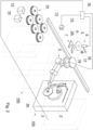
- Fig. 1 shows a system for feeding 1 of production apparatuses, in the embodiment shown the system feeds two production apparatuses P1, P2.
- the feeding system 1 comprises a plurality of unwinding apparatuses 100 for unwinding a web material from a bobbin 2.
- the system 1 may comprise a plurality of production apparatuses P1, P2, ... Pn.
- the feeding system 1 may comprise one production apparatus P1 and a plurality of unwinding apparatuses 100.
- Each of the production apparatuses P1, P2, ... Pn may be fed with a different type of material, each of the production apparatuses P1, P2, ... Pn may be fed with several different types of material.
- the system for feeding 1 of production apparatuses comprises a storage 3 of the bobbins 2, a manipulator 5, the manipulator 5 moving along a beam 13, i.e. along the path of movement T, a toothed bar or a guide screw may be used to move the manipulator along the beam 13 (a drive is not shown in the figure).
- the feeding system 1 may be provided with an inspection station 6 and a reversing table 7.
- the bobbin 2 comprises a carrier roll 8 ( Fig. 5 ) and a web material 9 wound onto such roll.
- the system 1 comprises a first container 10 for receiving waste sections of the web material of the bobbin 2 and a second container 12 for receiving empty carrier rolls 8.
- the storage of 3 the bobbins 2 contains multiple stacks of 14 the bobbins 2.
- the stacks 14 of the bobbins 2 may contain new bobbins, but also partially unwound bobbins recovered in other production stages or in other apparatuses where the production process required a change of a bobbin before the web material of the bobbin was fully used.
- both types of bobbins brought into the system are referred to as new bobbins.
- the system 1 may be provided with a monitoring camera 15 adapted to monitor the storage 3 of the new bobbins 2, and a system controller 16 adapted to preselect the new bobbin 2 from any of the stacks 14 of the new bobbins 2 in the storage 3 of the new bobbins 2, based on the image from the monitoring camera 15.
- the system 1 may be provided with a system controller 16 adapted to preselect the new bobbin 2 first from the stack 14 higher of any of the stacks 14 of the bobbins in the storage 3.
- the inspection station 6 ( Fig. 2 ) is provided with an inspection camera 17 which is mounted on a rotating arm 18.
- the arm 18 moves the inspection camera 17 along a circular path of movement 19, whereas the head 30 of the manipulator 5 moves the new bobbin 2 to the inspection station 6 and holds it horizontally so that the axis m of the new bobbin 2 substantially coincides with the centre of the circular path of movement 19 along which the inspection camera 17 moves.
- the new bobbin 2 to be inspected is indicated by a dashed line, whereas the head 30 that holds the new bobbin 2 is not shown.
- the system shown in Fig. 1 and Fig. 2 is provided with containers 10, 12 for waste materials.
- the manipulator 5 is adapted to put waste sections of the web material into the first container 10, furthermore, the manipulator 5 is adapted to put empty carrier rolls 8 into the second container 12.
- the waste sections of the web material are understood to be the waste section 9A of the new web material 9 and the waste section 29A of the old web material 29 remaining after the operation of splicing the new web material 9 with the old web material 29.
- the new web material 9 is understood to be the web that will be unwound after the change of the bobbins
- the old web material 29 is understood to be the web that is unwound before the change of the bobbins.
- the splicing unit in which the splicing of the new web material 9 with the old web material 29 takes place.
- the waste section 9A of the new web material is wound so that it can be received from the unwinding apparatus 100 by the jaw gripper 33 (as discussed below) situated on the head 30 of the manipulator 5.
- the section 29A of the old web material 29 is wound so that it can be received from the unwinding apparatus 100 by the jaw gripper 33.
- the system 1 is further provided with a second container 12 for the carrier rolls 8 of the used bobbins 2.
- the empty carrier roll 8 is gripped by the three finger gripper 31.
- Fig. 3 shows a feeding apparatus 100 from which a web of used bobbin 2' is being unwound and on which a web of new bobbin 2 has been placed.
- the web of the new bobbin 2 is fixed on a fixing mandrel 102, and the web material unwinding direction is indicated by an arrow U.
- the new web material 9 passes through the splicing unit 101 and is wound onto the receiving mandrel.
- the section of the new web 9 wound onto the receiving mandrel after passing through the splicing unit 101 is the waste section 9A of the new web material.
- the section of the used web material unwound from the bobbin 2' and remaining before the splicing unit 101 forms the waste section 29A of the old web material.
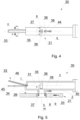
- the head 30 of the manipulator 5 shown in Fig. 4 and Fig. 5 in the feeding system 1 comprises the three finger gripper 31 for gripping the carrier roll 8 of the new bobbin 2 and the empty carrier roll 8, the jaw gripper 33 for gripping the end 9B of the new web material 9 of the new bobbin 2, for gripping the waste sections 9A, 29A of the web materials 9, 29, the sensor 34 for detecting the end 9B of the new web material 9 of the new bobbin 2, a distance meter 35 for measuring the distance of the head 30 of the manipulator 5 to the picked new bobbin 2 or to the fixing mandrel 102 on the unwinding apparatus 100, a head camera 36 for determining the position of the picked new bobbin 2.
- the three finger gripper 31 comprises three grooved pins, including two immovable pins 37 (immovable relative to the body 40 ) and one movable pin 38 arranged around the first axis k.
- the pins 37, 38 have circumferential grooves that allow the carrier roll 8 and thus the entire bobbin 2 to be kept stable, whereas the pins 37, 38 may have any elements, for example having sharp edges which facilitate fixing the carrier roll 8 on the mandrels 37, 38.
- the pins 37 are immovable mounted on the body 40 of the head 30, while the pin 38 is fixed on a slider 39 linearly slidably mounted on the body 40. The slider 39 is moved by means of an actuator 44.
- the pins 37 and 38 are arranged radially relative to the first axis k of the head 30.
- the pins 37 and 38 are shown in Fig. 4 and Fig. 5 in the holding position, i.e. they press on the carrier roll 8 of the bobbin 2 from the inside.
- the pin 38 moves in a direction perpendicular to the first axis k of the head 30.
- Substantially centrally within the three finger gripper 31 there is situated a head camera 36 for observing the space in front of the three finger gripper 31.
- the optical axis of the head camera 36 may coincide with the first axis k of the head 30.
- an optical distance meter 35 for measuring the distance to objects situated in front of the three finger gripper 31 along the direction of the first axis k (in Fig. 5 from the gripper 31 down the figure).
- the controller 16 is adapted so that on the basis of the image from the head camera 36 and the distance meter 35 it determines the height at which the top of the stack of new bobbins 2 is situated and the position of the three finger gripper 31 relative to the new bobbin 2.
- the image from the head camera 36 allows the movement of the manipulator 5 to be controlled so that it is possible to centrally position the three finger gripper 31 relative to the new bobbin 2 to be picked from the stack 14.
- the head 30 is provided with the jaw gripper 33 arranged along the second axis n of the head 30 which is arranged substantially perpendicular to the first axis k.
- the jaw gripper 33 comprises a first jaw 45 which is arranged along the second axis n, and a second jaw 46, which is rotatably mounted on the axis t.
- the second jaw 46 can be moved by an actuator (not shown) or any other drive.
- the head 30 can be provided with a vacuum gripper for gripping the end of the web material.
- the new bobbin 2 is picked up from the stack 14 of bobbins by means of the gripper 31 arranged on the head 30 of the manipulator 5, the manipulator moving along the path T to reach the correct stack 14.
- the distance meter 35 together with the head camera 36 check the position of the new bobbin 2 which is first on the stack 14.
- the head 30 is positioned above the stack 14 of the new bobbin 2, the head camera 36 captures an image including at least the carrier roll 8, the head camera 36 may capture an image of the entire new bobbin 2, while the distance meter 35 measures the distance of the lateral surface 2B of the new bobbin 2 from the head 30.
- the controller 16 determines the centre of the carrier roll 8.
- the head 30 together with the bobbin 2 is then moved so that the first axis k of the head 30 is positioned substantially coaxial with the axis m of the carrier roll 8.
- the manipulator 5 moves the head 30 so that the pins 37, 38 of the three finger gripper 31 are positioned inside the carrier roll 8, whereas the movement of the head 30 can be verified by means of the head camera 36 during the movement to pick up the new bobbin 2.
- the three finger gripper 31 grips the new bobbin 2 and then the manipulator 5 carries the picked new bobbin 2 to the inspection station 6 and keeps it there in a horizontal position.
- the bobbin 2 is identified and the direction of winding of the web material 9 on the bobbin 2 is verified.
- the circumferential surface 2A is scanned, the inspection camera 17 moves along the motion path 19 which is a circle and captures an image of the circumferential surface 2A of the bobbin 2, and the controller 16 reads the barcode 20 applied on this surface and finds the arrow 21 which indicates the unwinding direction of the web material 9.
- the camera 17 transmits the image to the controller 16 where the new bobbin 2 is identified. If an incorrect unwinding direction of the web material 9 is identified, the head 30 of the manipulator 5, after gripping the new bobbin 2, does not have the possibility to grip the new bobbin 2 from the side opposite to the gripping side, while the unwinding apparatus 100 has a determined unwinding direction U.
- the manipulator 30 carries the bobbin 2 to the reversing table 7 situated below the inspection station 6.
- the head 30 places the new bobbin 2 on the reversing table 7 during the downward movement and then grips the new bobbin 2 from the other side, i.e. from above.
- the manipulator 5 places the new bobbin 2 onto the fixing mandrel 102 of the unwinding apparatus 100. If the verification of correct positioning of the bobbins 2 on the stack 14 has been carried out previously, the step of verifying the position of the bobbin 2 and changing the gripping side as described above is omitted.
- the distance meter 35 checks the distance of the head 30 from the front surface of the fixing mandrel 102 so that the position of the head 30 relative to the fixing mandrel 102 can be verified before and during the movement of the head 30.
- the head 30 is withdrawn and then the jaw gripper 33 is pushed against the circumferential surface 2A of the new bobbin 2, then the bobbin 2 is rotated until the end 9B of the web material 9 is detected by the sensor 34 on the lower, first jaw 45 of the jaw gripper 33.
- the end 9B is gripped by clamping the upper, second jaw 46 of the jaw gripper 33 ( Fig. 6 ).
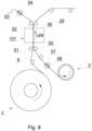
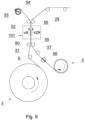
- the manipulator 5 moves the head 30 so that the end 9B is detached from the bobbin 2 and winds the new web material 9 between the rollers 51, 52, 55, 56 ( Fig. 7 ) of the unwinding apparatus 100 to and through the splicing unit 101 for splicing the unwound old web material 29 from the currently unwound used bobbin 2' with the new web material 9 of the new bobbin 2.
- the new strip of material 9 to be unwound from the new bobbin 2 is guided at the rolls 51, 52 and further to the first winding roller 53, whereas the first winding roller 53 having a slot 54 is axially displaced (perpendicular to the plane of the drawing) so that the new web material 9 is placed in the slot 54.
- the old web material 29 unwound from the old bobbin 2' is guided at the rolls 55, 56, further at the second winding roll 57, whereas the second winding roll 57 having a slot 58 is axially displaced (perpendicular to the plane of the drawing) so that the old web material 29 is placed in the slot 58.
- the amount of web material on the old bobbin 2' is checked, when the amount of web material decreases to a certain predetermined minimum, the first winding roller 53 starts to rotate at such a speed as to ensure that the speed v9 of the new web material 9 is equal to the speed v29 of the old web material 29 ( Fig. 9 ).
- a section of double-sided adhesive tape so-called "splicing insert" is fed between the new web material 9 and the old web material 29, and then the two web materials 9, 29 are pressed together by means of pressure rollers 61, 62 (not shown in Fig.
- At least one of these rollers is adjustable and after pressing against the other roller and pressing the webs 9 and 29 against each other, it moves away from the new web material 9, the web materials 9 and 29 remaining in motion during the splicing.
- a portion of the new web material 9 that cannot be used is cut off by means of the first knife 63, thus a waste section 9A of the new web material 9 is formed ( Fig. 10 ).
- a portion of the old web material 29 that cannot be used is cut off by the second knife 64, thus a waste section 29A of the old web material 29 is formed.
- the unwinding apparatus 100 After splicing the new web material 9 with the old web material 29 in the splicing unit 101, the unwinding apparatus 100 winds up the unused waste section 29A of the old web material 29 by rotating the second winding roll 57 ( Fig. 11 ), whereas the portion of the old web material remaining on the carrier roll 8 is also wound up, and the head 30 moves so that the jaw gripper 33 grips the unused waste section 29A of the old web material 29 and discards it into the first container 10, further, the unwinding apparatus 100 winds up the unused waste section 9A of the new web material 9 by rotating the first winding roller 53, and the head 30 moves so that the jaw gripper 33 grips the unused waste section 9A of the new web material 9 and discards it into the first container 10. The head 30 moves so that the three finger gripper 31 grips the empty carrier roll 8 of the used bobbin 2', carries the empty carrier roll 8 and discards it into the second container 12.
Landscapes
- Replacement Of Web Rolls (AREA)
Abstract
The object of the application is a system (1) for feeding web material (9, 29) to at least one production apparatus (P1, P2, P3, ... Pn), comprising a storage (3) of bobbins (2), a manipulator (5) provided with a head (30) for gripping and carrying the bobbin (2), unwinding apparatuses (100) for unwinding the web material (9, 29) from the successive bobbins (2, 2') and feeding the web material (9, 29) to the production apparatuses (P1, P2, P3, ... Pn). The head (30) is provided with an three finger gripper (31) for gripping the carrier roll (8) of the bobbin (2) and a jaw gripper (33) for gripping the end (9B) of the new web material (9) of the bobbin (2), the manipulator (5) being slidably mounted along the path (T) at the unwinding apparatuses (100), while the unwinding apparatus (100) comprises a splicing unit (101) for splicing the new web material (9) of the new bobbin (2) and the old web material (29) of the used bobbin (2'), and the manipulator (5) is adapted to wind through the new web material (9) of the bobbin (2) placed on the unwinding apparatus (100) to the splicing unit (101). The object of the application is also a manipulator head and a method for feeding at least one production apparatus.
Description
- The object of the invention is a system for feeding web material, a manipulator head for a system for feeding web material and a method for feeding web material.
- The feeding of web material is currently widely used. There is a demand for paper tubes used in packaging production. In the food industry, for example, multilayer tubes of diversified diameters are used in the hygiene products industry. Apparatuses manufacturing drinking straws as well as cylindrical packaging form continuous multilayer tubes from several web materials and require feeding from several unwinding apparatuses, such tubes are cut into individual straws or tubes. Web materials unwound from bobbins are also used in the tobacco industry for the manufacture of rod-like articles, in the tobacco industry, the production processes are carried out at high capacities and require frequent changes of semi-finished products in the form of webs of wrapping material. A web of wrapping material can be fed for an entire product or semi-finished product, for example to wrap a filler material, to wrap the mouthpiece of a finished product or to partially wrap a semi-finished product. Unwinding apparatuses adapted to splice successive web materials in order to maintain uninterrupted production are known.
- The document
EP1256538 A2 discloses a system and method of feeding a tobacco industry material to an operating unit. The system comprises a feeding unit for feeding the material (for example in the form of a bobbin) laid flat on a support to a corresponding unwinding pin of the feeding unit. According to the disclosure of the documentEP1256538 A2 , the bobbin is unwound on an unwinding mandrel mounted on the circumference of a rotatable platform rotating around a horizontal axis. The system allows the position of the unwinding mandrel to be changed to a vertical receiving position by changing the position of the rotating platform. - The publication
WO02092483 A1 WO02092483 A1 - The application
US9670021 B2 US9670021 B2 - The document
WO2016033399 A1 describes an apparatus for feeding, loading, splicing and unwinding wound web materials used for manufacturing disposable materials such as nappies. The apparatus described in the publicationWO2016033399 A1 is in the form of a multi-axis robot having an arm, a wrist subassembly, an end effector, a holder, a rocker arm and an extension arm. The multi-axis robot can determine the characteristics of a roll of rolled material, e.g. roll diameter, core diameter, type of material rolled into the roll, as well as its physical properties. According to the disclosure of the documentWO2016033399 A1 , the robot may have at least six independent axes of rotation. - There is a demand for an apparatus that feeds the bobbins of material efficiently and without the risk of feeding a wrong material and without the risk of feeding the bobbin in the opposite direction to the required unwinding direction. Today's production processes require feeding web materials at increasingly higher speeds. As the processes are run continuously, it is common to use apparatuses for changing the bobbins, which entails waste in the form of web material fragments at the beginning and at the end of the web. There is a demand to optimise the amount of waste in the form of unused web material. The process of feeding new bobbins can be automated, there is a demand on the part of the manufacturers that the supplied feeding systems have the capacity to handle multiple production apparatuses, including sorting of waste into paper and plastic waste. In the light of the presented state of the art, there is a need to provide a comprehensive solution allowing to automate the bobbin loading process and to maintain uninterrupted production, while checking the correctness of the fed bobbins and optimising the amount of waste.
- The object of the invention is a system for feeding web material to at least one production apparatus, comprising a storage of bobbins, a manipulator provided with a head for gripping and carrying the bobbin, an unwinding apparatus for unwinding the web material from successive bobbins and feeding the web material to the production apparatuses. The manipulator head is provided with a three finger gripper for gripping the carrier roll of the bobbin and a jaw gripper for gripping the end of a new web material of the bobbin. The manipulator is slidably mounted along a path at the unwinding apparatuses. Furthermore, the unwinding apparatus comprises a splicing unit for splicing the new web material of the new bobbin and the old web material of the used bobbin, and the manipulator is adapted to wind through the new web material of the bobbin placed on the unwinding apparatus to the splicing unit.
- Preferably, the system according to the invention is characterised in that the jaw gripper is provided with a sensor for checking the presence of the end of the new web material of the bobbin between the jaws of the jaw gripper and closing the jaw gripper when the end of the web material of the bobbin is detected.
- Preferably, the system according to the invention is characterised in that the splicing unit is provided with a first winding roll for accelerating the new web material and for winding a waste section of the new web material, and a second winding roll for winding a waste section of the old web material, such waste sections remaining after splicing the new web material with the old web material.
- Preferably, the system according to the invention is characterised in that the manipulator is adapted to remove the waste section of the new web material and the waste section of the old web material remaining after the web material splicing operation, and the system is further provided with a first container for discarding the waste sections of the web materials.
- Preferably, the system according to the invention is characterised in that the manipulator is adapted for discarding empty carrier rolls, and the system is further provided with a second container for discarding empty carrier rolls.
- Preferably, the system according to the invention is characterised in that the head is provided with a distance meter.
- Preferably, the system according to the invention is characterised in that the head is provided with a head camera and the controller is adapted to control the manipulator so that the first axis of the head is in the axis of the bobbin before the bobbin is gripped.
- Preferably, the system according to the invention is characterised in that the controller is adapted to determine the height at which the top of the bobbin stack is situated, based on the image from the head camera and the information of the distance meter.
- Furthermore, the object of the invention is the manipulator head for the system for feeding the web material to at least one production apparatus for gripping and carrying the bobbin, provided with a three finger gripper adapted to grip the carrier roll of the bobbin, the three finger gripper being provided with two stationary pins and one movable pin driven by an actuator, and a jaw gripper adapted to grip the end of the new web material of the bobbin.
- Preferably, the head according to the invention is characterised by being provided with the distance meter.
- Preferably, the head according to the invention is characterised by being provided with the head camera.
- Preferably, the head according to the invention is characterised in that the jaw gripper is provided with the sensor for checking the presence of the end of a new web material of the bobbin between the jaws of the jaw gripper.
- The object of the invention is also a method for feeding web material to at least one production apparatus, comprising steps of: moving a manipulator along the path at the unwinding apparatuses and positioning the manipulator head above the stack of the bobbins. Then checking the position of the uppermost bobbin on the basis of the image from the head camera and the signal from the distance meter on the head, after that gripping the bobbin from the stack of the bobbins by means of the manipulator provided with the three finger gripper, taking into account the position of the uppermost bobbin. In the next step, carrying the bobbin by means of the head to the unwinding apparatus of the selected production apparatus directly opposite a fixing mandrel and checking the position of the three finger gripper relative to the fixing mandrel. Then placing the bobbin on the fixing mandrel, taking into account the position of the fixing mandrel, pushing the jaw gripper of the manipulator against the circumferential surface of the placed bobbin, rotating the placed bobbin until the end of the web material is detected by the sensor on the jaw gripper. Gripping the end of the web material by means of the jaw gripper, detaching the end of the web material and winding the new web material by means of the jaw gripper between the rolls of the unwinding apparatus to the splicing unit for splicing the new web material and the old web material, then rotating the first winding roll and accelerating the new web material to a speed equal to the speed of the old web material, after that placing a splicing insert between the old web material and the new web material. Then pressing the old web material against the new web material and splicing the old web material with the new web material by means of the splicing insert, cutting off the unused waste section of the new web material with a first knife, winding up the unused waste section of the new web material by means of a first winding roll, cutting off the unused waste section of the old web material by means of a second knife, winding up the unused waste section of the old web material by means of a second winding roll. In the next step, gripping the unused waste section of the old web material with the jaw gripper and discarding it into a first container, gripping the unused waste section of the new web material with the jaw gripper and discarding it into the first container, and then gripping the empty carrier roll of the used bobbin with the three finger gripper and discarding it into a second container.
- The system according to the invention provides a universal feeding system for use in production lines in many industrial branches. The manipulator head used in the system is a multifunctional head so as to handle the process of placing a new bobbin, unwinding the beginning of the web as well as receiving waste materials. The central location of the head camera makes it possible to verify the position of the three finger gripper relative to the carrier roll of the bobbin both before and during the head movement towards the new bobbin or both before and during the head movement towards the mandrel on the unwinding unit, as the camera remains positioned centrally relative to the carrier roll or the mandrel during the three finger gripper's approach movement. The three finger gripper can both pick up a new bobbin and take away an empty carrier roll after a web material has been used. The jaw gripper makes it possible both to start unwinding the web material and to pick up unused waste sections of the web material. The system and method according to the invention allow automating the process of loading the bobbin by eliminating operator errors associated with feeding a wrong material or bobbin in a way opposite to the required unwinding direction of the web material on the unwinding apparatus. The elimination of human errors, on the other hand, carries a further beneficial technical effect related to the reduction of the labour intensity of the process. The system and method according to the invention allow optimising the use of materials as well as proper segregating of waste, which results from the multifunctionality of the head capable not only of placing a new bobbin, but also of receiving waste materials.
- The object of the invention is shown in more detail in a preferred embodiment in a drawing in which:
-
Fig. 1 shows a system for feeding web material in a top view; -
Fig. 2 shows the system for feeding web material in a perspective view; -
Fig. 3 shows a feeding apparatus; -
Fig. 4 shows a manipulator head in a view towards the axis of a three finger gripper in a position when the three finger gripper is not holding a bobbin; -
Fig. 5 shows the manipulator head in a view perpendicular to the axis of a three finger gripper, the pins are positioned as inFig. 4 and a jaw gripper is open; -
Fig. 6 shows a cross-section A-A through the jaw gripper ofFig. 4 , -
Fig. 7 shows placing a new web material on an unwinding apparatus, -
Fig. 8 shows the unwinding apparatus after placing a new web material, -
Fig. 9 shows the equalisation of speed of the new web material and the old web material, -
Fig. 10 shows the splicing of the new web material and the old web material, and the cutting off of unused parts of such web materials, and -
Fig. 11 shows the unwinding apparatus after winding the waste sections of the old and new web materials. -
Fig. 1 shows a system for feeding 1 of production apparatuses, in the embodiment shown the system feeds two production apparatuses P1, P2. Thefeeding system 1 comprises a plurality of unwindingapparatuses 100 for unwinding a web material from abobbin 2. Thesystem 1 may comprise a plurality of production apparatuses P1, P2, ... Pn. Thefeeding system 1 may comprise one production apparatus P1 and a plurality of unwindingapparatuses 100. Each of the production apparatuses P1, P2, ... Pn may be fed with a different type of material, each of the production apparatuses P1, P2, ... Pn may be fed with several different types of material. The system for feeding 1 of production apparatuses comprises astorage 3 of thebobbins 2, amanipulator 5, themanipulator 5 moving along abeam 13, i.e. along the path of movement T, a toothed bar or a guide screw may be used to move the manipulator along the beam 13 (a drive is not shown in the figure). Thefeeding system 1 may be provided with aninspection station 6 and a reversing table 7. Thebobbin 2 comprises a carrier roll 8 (Fig. 5 ) and aweb material 9 wound onto such roll. Furthermore, thesystem 1 comprises afirst container 10 for receiving waste sections of the web material of thebobbin 2 and asecond container 12 for receiving empty carrier rolls 8. - In the embodiment in
Fig. 1 , the storage of 3 thebobbins 2 contains multiple stacks of 14 thebobbins 2. Thestacks 14 of thebobbins 2 may contain new bobbins, but also partially unwound bobbins recovered in other production stages or in other apparatuses where the production process required a change of a bobbin before the web material of the bobbin was fully used. For the sake of simplicity, both types of bobbins brought into the system are referred to as new bobbins. Thesystem 1 may be provided with amonitoring camera 15 adapted to monitor thestorage 3 of thenew bobbins 2, and asystem controller 16 adapted to preselect thenew bobbin 2 from any of thestacks 14 of thenew bobbins 2 in thestorage 3 of thenew bobbins 2, based on the image from the monitoringcamera 15. Thesystem 1 may be provided with asystem controller 16 adapted to preselect thenew bobbin 2 first from thestack 14 higher of any of thestacks 14 of the bobbins in thestorage 3. - The inspection station 6 (
Fig. 2 ) is provided with aninspection camera 17 which is mounted on arotating arm 18. Thearm 18 moves theinspection camera 17 along a circular path ofmovement 19, whereas thehead 30 of themanipulator 5 moves thenew bobbin 2 to theinspection station 6 and holds it horizontally so that the axis m of thenew bobbin 2 substantially coincides with the centre of the circular path ofmovement 19 along which theinspection camera 17 moves. InFig. 1 andFig. 2 , thenew bobbin 2 to be inspected is indicated by a dashed line, whereas thehead 30 that holds thenew bobbin 2 is not shown. Theinspection camera 17 is adapted to observe thecircumferential surface 2A of thenew bobbin 2 held by themanipulator 5, while thecontroller 16 is adapted to identify thenew bobbin 2 by reading the bar code 20 (Fig. 5 ) and/or determining the unwinding direction of thenew web material 9 from thenew bobbin 2 based on the image from theinspection camera 17, the unwinding direction being defined by anarrow 21 placed on thecircumferential surface 2A of thebobbin 2. - The system shown in
Fig. 1 andFig. 2 is provided withcontainers manipulator 5 is adapted to put waste sections of the web material into thefirst container 10, furthermore, themanipulator 5 is adapted to put empty carrier rolls 8 into thesecond container 12. The waste sections of the web material are understood to be thewaste section 9A of thenew web material 9 and thewaste section 29A of theold web material 29 remaining after the operation of splicing thenew web material 9 with theold web material 29. Thenew web material 9 is understood to be the web that will be unwound after the change of the bobbins, theold web material 29 is understood to be the web that is unwound before the change of the bobbins. As 101 is denoted the splicing unit in which the splicing of thenew web material 9 with theold web material 29 takes place. Thewaste section 9A of the new web material is wound so that it can be received from the unwindingapparatus 100 by the jaw gripper 33 (as discussed below) situated on thehead 30 of themanipulator 5. Similarly, thesection 29A of theold web material 29 is wound so that it can be received from the unwindingapparatus 100 by thejaw gripper 33. Thesystem 1 is further provided with asecond container 12 for the carrier rolls 8 of the usedbobbins 2. Theempty carrier roll 8 is gripped by the threefinger gripper 31. -
Fig. 3 shows afeeding apparatus 100 from which a web of used bobbin 2' is being unwound and on which a web ofnew bobbin 2 has been placed. The web of thenew bobbin 2 is fixed on a fixingmandrel 102, and the web material unwinding direction is indicated by an arrow U. Thenew web material 9 passes through thesplicing unit 101 and is wound onto the receiving mandrel. The section of thenew web 9 wound onto the receiving mandrel after passing through thesplicing unit 101 is thewaste section 9A of the new web material. The section of the used web material unwound from the bobbin 2' and remaining before thesplicing unit 101 forms thewaste section 29A of the old web material. - The
head 30 of themanipulator 5 shown inFig. 4 and Fig. 5 in thefeeding system 1 comprises the threefinger gripper 31 for gripping thecarrier roll 8 of thenew bobbin 2 and theempty carrier roll 8, thejaw gripper 33 for gripping theend 9B of thenew web material 9 of thenew bobbin 2, for gripping thewaste sections web materials sensor 34 for detecting theend 9B of thenew web material 9 of thenew bobbin 2, adistance meter 35 for measuring the distance of thehead 30 of themanipulator 5 to the pickednew bobbin 2 or to the fixingmandrel 102 on theunwinding apparatus 100, ahead camera 36 for determining the position of the pickednew bobbin 2. - in
Fig. 5 , the first axis of thehead 30 is indicated as k. The threefinger gripper 31 comprises three grooved pins, including two immovable pins 37 (immovable relative to the body 40) and onemovable pin 38 arranged around the first axis k. Thepins carrier roll 8 and thus theentire bobbin 2 to be kept stable, whereas thepins carrier roll 8 on themandrels pins 37 are immovable mounted on thebody 40 of thehead 30, while thepin 38 is fixed on aslider 39 linearly slidably mounted on thebody 40. Theslider 39 is moved by means of anactuator 44. Thepins head 30. Thepins Fig. 4 and Fig. 5 in the holding position, i.e. they press on thecarrier roll 8 of thebobbin 2 from the inside. Thepin 38 moves in a direction perpendicular to the first axis k of thehead 30. Substantially centrally within the threefinger gripper 31, there is situated ahead camera 36 for observing the space in front of the threefinger gripper 31. The optical axis of thehead camera 36 may coincide with the first axis k of thehead 30. Next to thehead camera 36, there is situated anoptical distance meter 35 for measuring the distance to objects situated in front of the threefinger gripper 31 along the direction of the first axis k (inFig. 5 from thegripper 31 down the figure). - The
controller 16 is adapted so that on the basis of the image from thehead camera 36 and thedistance meter 35 it determines the height at which the top of the stack ofnew bobbins 2 is situated and the position of the threefinger gripper 31 relative to thenew bobbin 2. The image from thehead camera 36 allows the movement of themanipulator 5 to be controlled so that it is possible to centrally position the threefinger gripper 31 relative to thenew bobbin 2 to be picked from thestack 14. - The
head 30 is provided with thejaw gripper 33 arranged along the second axis n of thehead 30 which is arranged substantially perpendicular to the first axis k. Thejaw gripper 33 comprises afirst jaw 45 which is arranged along the second axis n, and asecond jaw 46, which is rotatably mounted on the axis t. Thesecond jaw 46 can be moved by an actuator (not shown) or any other drive. Thehead 30 can be provided with a vacuum gripper for gripping the end of the web material. - In order to load a new bobbin, the
new bobbin 2 is picked up from thestack 14 of bobbins by means of thegripper 31 arranged on thehead 30 of themanipulator 5, the manipulator moving along the path T to reach thecorrect stack 14. During the gripping, thedistance meter 35 together with thehead camera 36 check the position of thenew bobbin 2 which is first on thestack 14. Thehead 30 is positioned above thestack 14 of thenew bobbin 2, thehead camera 36 captures an image including at least thecarrier roll 8, thehead camera 36 may capture an image of the entirenew bobbin 2, while thedistance meter 35 measures the distance of thelateral surface 2B of thenew bobbin 2 from thehead 30. Thecontroller 16 determines the centre of thecarrier roll 8. Thehead 30 together with thebobbin 2 is then moved so that the first axis k of thehead 30 is positioned substantially coaxial with the axis m of thecarrier roll 8. Themanipulator 5 moves thehead 30 so that thepins finger gripper 31 are positioned inside thecarrier roll 8, whereas the movement of thehead 30 can be verified by means of thehead camera 36 during the movement to pick up thenew bobbin 2. The threefinger gripper 31 grips thenew bobbin 2 and then themanipulator 5 carries the pickednew bobbin 2 to theinspection station 6 and keeps it there in a horizontal position. At theinspection station 6, thebobbin 2 is identified and the direction of winding of theweb material 9 on thebobbin 2 is verified. Thebobbin 2 has, on its circumferential surface, abarcode 20 which contains data such as, inter alia, the type of the web material, the width of the web material, the diameter of the carrier roll, etc. Furthermore, thebobbin 2 has, on itscircumferential surface 2A, anarrow 21 which indicates the winding direction of theweb material 9 so that thecontroller 16, upon receiving the image from theinspection camera 17, has the information whether thebobbin 2 is gripped correctly, i.e. so that when thebobbin 2 is placed on the fixingmandrel 102 of theunwinding apparatus 100, theweb material 9 will be unwound according to the unwinding direction U defined on theunwinding apparatus 100. Thecircumferential surface 2A is scanned, theinspection camera 17 moves along themotion path 19 which is a circle and captures an image of thecircumferential surface 2A of thebobbin 2, and thecontroller 16 reads thebarcode 20 applied on this surface and finds thearrow 21 which indicates the unwinding direction of theweb material 9. Thecamera 17 transmits the image to thecontroller 16 where thenew bobbin 2 is identified. If an incorrect unwinding direction of theweb material 9 is identified, thehead 30 of themanipulator 5, after gripping thenew bobbin 2, does not have the possibility to grip thenew bobbin 2 from the side opposite to the gripping side, while theunwinding apparatus 100 has a determined unwinding direction U. In the event of incorrect gripping, it is necessary to change the gripping side of thenew bobbin 2. Themanipulator 30 carries thebobbin 2 to the reversing table 7 situated below theinspection station 6. Thehead 30 places thenew bobbin 2 on the reversing table 7 during the downward movement and then grips thenew bobbin 2 from the other side, i.e. from above. After gripping thenew bobbin 2 again, themanipulator 5 places thenew bobbin 2 onto the fixingmandrel 102 of theunwinding apparatus 100. If the verification of correct positioning of thebobbins 2 on thestack 14 has been carried out previously, the step of verifying the position of thebobbin 2 and changing the gripping side as described above is omitted. When placing thebobbin 2, thehead camera 36 together with thedistance meter 35 verify the position of thehead 30 relative to the fixingmandrel 102, the first axis k of thehead 30 being positioned substantially parallel to the axis of the fixingmandrel 102. The recorded image of the front surface of themandrel 102 on theunwinding apparatus 100 allows thehead 30 to be controlled so that the first axis k of thehead 30 is aligned coaxially with the axis of the fixingmandrel 102, furthermore, the position of thepins mandrel 102 into which thepins new bobbin 2. Thedistance meter 35 checks the distance of thehead 30 from the front surface of the fixingmandrel 102 so that the position of thehead 30 relative to the fixingmandrel 102 can be verified before and during the movement of thehead 30. After placing thebobbin 2 onto the fixingmandrel 102, thehead 30 is withdrawn and then thejaw gripper 33 is pushed against thecircumferential surface 2A of thenew bobbin 2, then thebobbin 2 is rotated until theend 9B of theweb material 9 is detected by thesensor 34 on the lower,first jaw 45 of thejaw gripper 33. After detecting theend 9B and stopping the rotational movement of thebobbin 2, theend 9B is gripped by clamping the upper,second jaw 46 of the jaw gripper 33 (Fig. 6 ). Themanipulator 5 moves thehead 30 so that theend 9B is detached from thebobbin 2 and winds thenew web material 9 between therollers Fig. 7 ) of theunwinding apparatus 100 to and through thesplicing unit 101 for splicing the unwoundold web material 29 from the currently unwound used bobbin 2' with thenew web material 9 of thenew bobbin 2. - As shown in
Fig. 8 , the new strip ofmaterial 9 to be unwound from thenew bobbin 2 is guided at therolls roller 53, whereas the first windingroller 53 having aslot 54 is axially displaced (perpendicular to the plane of the drawing) so that thenew web material 9 is placed in theslot 54. Theold web material 29 unwound from the old bobbin 2' is guided at therolls roll 57, whereas the second windingroll 57 having aslot 58 is axially displaced (perpendicular to the plane of the drawing) so that theold web material 29 is placed in theslot 58. The amount of web material on the old bobbin 2' is checked, when the amount of web material decreases to a certain predetermined minimum, the first windingroller 53 starts to rotate at such a speed as to ensure that the speed v9 of thenew web material 9 is equal to the speed v29 of the old web material 29 (Fig. 9 ). Once the speeds v9 and v29 are equal, a section of double-sided adhesive tape so-called "splicing insert" is fed between thenew web material 9 and theold web material 29, and then the twoweb materials pressure rollers 61, 62 (not shown inFig. 7 ,8 ,9 ), at least one of these rollers is adjustable and after pressing against the other roller and pressing thewebs new web material 9, theweb materials new web material 9 that cannot be used is cut off by means of thefirst knife 63, thus awaste section 9A of thenew web material 9 is formed (Fig. 10 ). A portion of theold web material 29 that cannot be used is cut off by thesecond knife 64, thus awaste section 29A of theold web material 29 is formed. After splicing thenew web material 9 with theold web material 29 in thesplicing unit 101, the unwindingapparatus 100 winds up theunused waste section 29A of theold web material 29 by rotating the second winding roll 57 (Fig. 11 ), whereas the portion of the old web material remaining on thecarrier roll 8 is also wound up, and thehead 30 moves so that thejaw gripper 33 grips theunused waste section 29A of theold web material 29 and discards it into thefirst container 10, further, the unwindingapparatus 100 winds up theunused waste section 9A of thenew web material 9 by rotating the first windingroller 53, and thehead 30 moves so that thejaw gripper 33 grips theunused waste section 9A of thenew web material 9 and discards it into thefirst container 10. Thehead 30 moves so that the threefinger gripper 31 grips theempty carrier roll 8 of the used bobbin 2', carries theempty carrier roll 8 and discards it into thesecond container 12. -
1 feeding system 35 distance meter 2 bobbin / new bobbin 36 head camera 2' used bobbin 37 pins 2A circumferential surface of the bobbin 38 movable pin 2B lateral surface of the bobbin 39 slider 3 storage 40 body 5 manipulator 44 actuator 6 inspection station 45 first jaw 7 reversing table 46 second jaw 8 carrier roller 51, 52, 55, 56 rolls of unwinding apparatus 9 web material / new web material 53 first winding roll 9A waste section of new web material 54 slot of first winding roll 9B end of web material 57 second winding roll 10 first container 58 slot of second winding roll 12 second container 60 splicing insert 13 beam 61, 62 pressure rollers 14 bobbin stack 63 first knife 15 monitoring camera 64 second knife 16 controller 100 unwinding apparatus 17 inspection camera 101 splicing unit 18 arm 102 fixing mandrel 19 path of movement m axis of new bobbin 20 barcode k first axis of the head 21 arrow (indication of unwinding direction) n axis of the jaw gripper 29 old web material P1 first production apparatus 29A waste section of old web material P2 second production apparatus 30 head T path of movement 31 three finger gripper U unwinding direction of web material 33 jaw gripper v9 speed of new web material 34 sensor v29 speed of old web material
Claims (13)
- A system (1) for feeding web material (9, 29) to at least one production apparatus (P1, P2, P3, ... Pn) comprising- a storage (3) of bobbins (2),- a manipulator (5) provided with a head (30) for gripping and carrying the bobbin (2),- an unwinding apparatus (100) for unwinding the web material (9, 29) from successive bobbins (2, 2') and feeding the web material (9, 29) to the production apparatuses (P1, P2, P3, ... Pn),whereas the head (30) is provided with a three finger gripper (31) for gripping the carrier roll (8) of the bobbin (2) and a jaw gripper (33) for gripping the end (9B) of the new web material (9) of the bobbin (2),the manipulator (5) is slidably mounted along the path (T) at the unwinding apparatuses (100),while the unwinding apparatus (100) comprises a splicing unit (101) for splicing the new web material (9) of the new bobbin (2) and the old web material (29) of the used bobbin (2'),and the manipulator (5) is adapted to wind through the new web material (9) of the bobbin (2) placed on the unwinding apparatus (100) to the splicing unit (101).
- The system as in claim 1, characterised in that the jaw gripper (33) is provided with a sensor (34) for checking the presence of the end (9B) of the new web material (9) of the bobbin (2) between the jaws of the jaw gripper (33) and closing the jaw gripper (33) when the end (9B) of the web material (9) of the bobbin (2) is detected.
- The system as in claim 1 or 2, characterized in that the splicing unit (101) is provided with a first winding roll (53) for accelerating the new web material (9) and for winding a waste section (9A) of the new web material (9) and a second winding roll (57) for winding a waste section (29A) of the old web material (29), such waste sections (9A, 29A) remaining after splicing the new web material (9) with the old web material (29).
- The system as in any of the claims 1 to 3, characterised in that the manipulator (5) is adapted to remove the waste section (9A) of the new web material (9) and the waste section (29A) of the old web material (29) remaining after the web material (9, 29) splicing operation, and the system (1) is further provided with a first container (10) for discarding the waste sections (9A, 29A) of the web materials (9, 29).
- The system as in any of the claims 1 to 4, characterised in that the manipulator (5) is adapted for discarding empty carrier rolls (8) and the system (1) is further provided with a second container (12) for discarding empty carrier rolls (8).
- The system as in any of the preceding claims 1 to 5, characterised in that the head (30) is provided with a distance meter (35).
- The system as in any of the claims 1 to 6, characterised in that the head (30) is provided with a head camera (36) and the controller (16) is adapted to control the manipulator (5) so that the first axis (k) of the head (30) is in the axis (m) of the bobbin (2) before the bobbin (2) is gripped.
- The system as in any of the claims 1 to 7, characterised in that the controller (16) is adapted to determine the height at which the top of the bobbin (2) stack (14) is situated, based on the image from the head camera (36) and the information of the distance meter (35).
- A manipulator head (5) for the system (1) for feeding the web material (9, 29) to at least one production apparatus (P1, P2, P3, ... Pn) for gripping and carrying the bobbin (2), is provided witha three finger gripper (31) adapted to grip the carrier roller (8) of the bobbin (2), the three finger gripper being provided with two stationary pins (37) and one movable pin (38) driven by an actuator (44), anda jaw gripper (33) adapted to grip the end (9B) of the new web material (9) of the bobbin (2).
- The head as in claim 9, characterised by being provided with a distance meter (35).
- The head according to claims 9 or 10, characterised by being provided with a head camera (36).
- The head as in any of the claims 9 to 11, characterised in that the jaw gripper is provided with a sensor (34) for checking the presence of the end (9B) of a new web material (9) of the bobbin (2) between the jaws of the jaw gripper (33).
- A method for feeding web material (9, 29) to at least one production apparatus (P1, P2, P3, ... Pn) comprising steps of:moving a manipulator (5) along the path of movement (T) at the unwinding apparatuses (100), and positioning the head (30) of the manipulator (5) above the stack (14) of the bobbins (2),checking the position of the uppermost bobbin (2) on the basis of the image from the head camera (36) and the signal from the distance meter (35) on the head (30),gripping the bobbin (2) from the stack (14) of the bobbins (2) by means of the manipulator (5) provided with the three finger gripper (31), taking into account the position of the uppermost bobbin (2),carrying the bobbin (2) by means of the head (30) to the unwinding apparatus (100) of the selected production apparatus (P1, P2, P3, ... Pn) directly opposite the fixing mandrel (102) and checking the position of the three finger gripper (31) relative to the fixing mandrel (102), then placing the bobbin (2) on the fixing mandrel (102), taking into account the position of the mandrel (102),pushing the jaw gripper (33) of the manipulator (5) against the circumferential surface (2A) of the placed bobbin (2),rotating the placed bobbin (2) until the end (9B) of the web material (9) is detected by the sensor (34) on the jaw gripper (33),gripping the end (9B) of the web material (9) by means of the jaw gripper (33),detaching the end (9B) of the web material (9) and winding the new web material (9) by the jaw gripper (33) between the rolls (51, 52, 55, 56) of the unwinding apparatus (100) to the splicing unit (101) for splicing the new web material (9) and the old web material (29),rotating the first winding roll (53) and accelerating the new web material (9) to a speed (v9) equal to the speed (v29) of the old web material (29),placing a splicing insert (60) between the old web material (9) and the new web material (29),pressing the old web material (9) against the new web material (29), splicing the old web material (9) with the new web material (29) by means of the splicing insert (60),cutting off the unused waste section (9A) of the new web material (9) by means of a first knife (63),winding up the unused waste section (9A) of the new web material (9) by means of a first winding roll (53),cutting off the unused waste section (29A) of the old web material (29) by means of a second knife (64),winding up the unused waste section (29A) of the old web material (29) by means of a second winding roll (57),gripping the unused waste section (29A) of the old web material (29) with the jaw gripper (33) and discarding it into a first container (10),gripping the unused waste section (9A) of the new web material (9) with the jaw gripper (33) and discarding it into the first container (10),gripping the empty carrier roll (8) of the used bobbin (2') by means of the three finger gripper (31) and discarding it into a second container (12).
Priority Applications (2)
| Application Number | Priority Date | Filing Date | Title |
|---|---|---|---|
| EP23206752.0A EP4549351A1 (en) | 2023-10-30 | 2023-10-30 | System for feeding web material, manipulator head for system for feeding web material and method for feeding web material |
| PCT/IB2024/060638 WO2025094040A1 (en) | 2023-10-30 | 2024-10-29 | System for feeding web material, manipulator head for system for feeding web material and method for feeding web material |
Applications Claiming Priority (1)
| Application Number | Priority Date | Filing Date | Title |
|---|---|---|---|
| EP23206752.0A EP4549351A1 (en) | 2023-10-30 | 2023-10-30 | System for feeding web material, manipulator head for system for feeding web material and method for feeding web material |
Publications (1)
| Publication Number | Publication Date |
|---|---|
| EP4549351A1 true EP4549351A1 (en) | 2025-05-07 |
Family
ID=89386037
Family Applications (1)
| Application Number | Title | Priority Date | Filing Date |
|---|---|---|---|
| EP23206752.0A Pending EP4549351A1 (en) | 2023-10-30 | 2023-10-30 | System for feeding web material, manipulator head for system for feeding web material and method for feeding web material |
Country Status (2)
| Country | Link |
|---|---|
| EP (1) | EP4549351A1 (en) |
| WO (1) | WO2025094040A1 (en) |
Citations (8)
| Publication number | Priority date | Publication date | Assignee | Title |
|---|---|---|---|---|
| GB2135283A (en) * | 1983-02-15 | 1984-08-30 | Gd Spa | Splicing webs |
| US5935361A (en) * | 1996-07-17 | 1999-08-10 | Fuji Photo Film Co., Ltd. | Web splicing preparation method and apparatus |
| EP1256538A2 (en) | 2001-05-11 | 2002-11-13 | G.D Societ Per Azioni | Method and unit for feeding packaging material to an operating unit |
| WO2002092483A1 (en) | 2001-05-11 | 2002-11-21 | G.D Societa' Per Azioni | Method and device for feeding reels to a machine |
| WO2016033399A1 (en) | 2014-08-28 | 2016-03-03 | The Procter & Gamble Company | Web material unwind apparatus |
| US9670021B2 (en) | 2014-08-28 | 2017-06-06 | The Procter & Gamble Company | Mandrel |
| JP2022148432A (en) * | 2021-03-24 | 2022-10-06 | 株式会社フジキカイ | Method of automatically connecting packaging films |
| US20230183037A1 (en) * | 2021-12-13 | 2023-06-15 | Fameccanica.Data S.P.A. | Reel handling robot and a method for handling reels of web material |
-
2023
- 2023-10-30 EP EP23206752.0A patent/EP4549351A1/en active Pending
-
2024
- 2024-10-29 WO PCT/IB2024/060638 patent/WO2025094040A1/en active Pending
Patent Citations (9)
| Publication number | Priority date | Publication date | Assignee | Title |
|---|---|---|---|---|
| GB2135283A (en) * | 1983-02-15 | 1984-08-30 | Gd Spa | Splicing webs |
| US5935361A (en) * | 1996-07-17 | 1999-08-10 | Fuji Photo Film Co., Ltd. | Web splicing preparation method and apparatus |
| EP1256538A2 (en) | 2001-05-11 | 2002-11-13 | G.D Societ Per Azioni | Method and unit for feeding packaging material to an operating unit |
| WO2002092483A1 (en) | 2001-05-11 | 2002-11-21 | G.D Societa' Per Azioni | Method and device for feeding reels to a machine |
| US20060051185A1 (en) * | 2001-05-11 | 2006-03-09 | Mario Spatafora | Method and device for feeding reels to a machine |
| WO2016033399A1 (en) | 2014-08-28 | 2016-03-03 | The Procter & Gamble Company | Web material unwind apparatus |
| US9670021B2 (en) | 2014-08-28 | 2017-06-06 | The Procter & Gamble Company | Mandrel |
| JP2022148432A (en) * | 2021-03-24 | 2022-10-06 | 株式会社フジキカイ | Method of automatically connecting packaging films |
| US20230183037A1 (en) * | 2021-12-13 | 2023-06-15 | Fameccanica.Data S.P.A. | Reel handling robot and a method for handling reels of web material |
Also Published As
| Publication number | Publication date |
|---|---|
| WO2025094040A1 (en) | 2025-05-08 |
Similar Documents
| Publication | Publication Date | Title |
|---|---|---|
| JP3633984B2 (en) | Needle-suture assembly and packaging automatic device and process | |
| CN106660727B (en) | For operating the method and apparatus of flat material and/or thin-film material on reel | |
| USRE31839E (en) | Bobbin transport apparatus and method | |
| CN107683249B (en) | Method and apparatus for feeding, supplying and changing reels with packaging material in a packaging machine | |
| US8582863B2 (en) | Winding device and assembly comprising a winding device | |
| EP3578344B1 (en) | A method for automatically loading reels into an unwinding assembly | |
| US11225390B2 (en) | Method and apparatus for feeding and splicing sheet of material wound in a bobbin | |
| IT9020048A1 (en) | PROCEDURE FOR THE TRANSMISSION OF INFORMATION AND PRODUCT CHARACTERISTICS OF A TEXTILE SPOOL BY MEANS OF AN INFORMATION SUPPORT | |
| JP7657875B2 (en) | Cable processing machine device, method for removing a cable from a removal trough of a cable processing machine, and cable replacement device for a cable processing machine | |
| WO2023044244A1 (en) | Automated yarn package handling system and method | |
| JP5804891B2 (en) | Empty tube gripper for traverse package changer | |
| WO2024218739A1 (en) | A system for loading a bobbin into an unwinder, a manipulator for loading the roll and a method for loading a roll into an unwinder | |
| WO2025094040A1 (en) | System for feeding web material, manipulator head for system for feeding web material and method for feeding web material | |
| US12560424B2 (en) | Machine for controlling the shape of a reel of web product | |
| US8052079B2 (en) | Coiler and method for manufacturing a coil | |
| US5971590A (en) | Method for fetching heads from stacks | |
| CN110882022B (en) | Universal winder for multi-tray design | |
| KR102960130B1 (en) | Automatic tissue manufacturing apparatus | |
| CN223684842U (en) | A barbed wire production mechanism | |
| JP7864138B2 (en) | A device for controlling the reel shape of web products. | |
| WO2025186736A2 (en) | Machine for making brushes | |
| WO2019102414A1 (en) | Assembly and method to handle a web or wire bobbin | |
| JPH03120162A (en) | Rewinding machine | |
| JPH06211207A (en) | Coin packer |
Legal Events
| Date | Code | Title | Description |
|---|---|---|---|
| PUAI | Public reference made under article 153(3) epc to a published international application that has entered the european phase |
Free format text: ORIGINAL CODE: 0009012 |
|
| STAA | Information on the status of an ep patent application or granted ep patent |
Free format text: STATUS: THE APPLICATION HAS BEEN PUBLISHED |
|
| AK | Designated contracting states |
Kind code of ref document: A1 Designated state(s): AL AT BE BG CH CY CZ DE DK EE ES FI FR GB GR HR HU IE IS IT LI LT LU LV MC ME MK MT NL NO PL PT RO RS SE SI SK SM TR |
|
| STAA | Information on the status of an ep patent application or granted ep patent |
Free format text: STATUS: REQUEST FOR EXAMINATION WAS MADE |
|
| 17P | Request for examination filed |
Effective date: 20251107 |