EP4549334A1 - Two-part container, and cap-equipped two-part container - Google Patents
Two-part container, and cap-equipped two-part container Download PDFInfo
- Publication number
- EP4549334A1 EP4549334A1 EP23830782.1A EP23830782A EP4549334A1 EP 4549334 A1 EP4549334 A1 EP 4549334A1 EP 23830782 A EP23830782 A EP 23830782A EP 4549334 A1 EP4549334 A1 EP 4549334A1
- Authority
- EP
- European Patent Office
- Prior art keywords
- container
- mouth
- engagement piece
- outer container
- walled
- Prior art date
- Legal status (The legal status is an assumption and is not a legal conclusion. Google has not performed a legal analysis and makes no representation as to the accuracy of the status listed.)
- Withdrawn
Links
Images





Classifications
-
- B—PERFORMING OPERATIONS; TRANSPORTING
- B65—CONVEYING; PACKING; STORING; HANDLING THIN OR FILAMENTARY MATERIAL
- B65D—CONTAINERS FOR STORAGE OR TRANSPORT OF ARTICLES OR MATERIALS, e.g. BAGS, BARRELS, BOTTLES, BOXES, CANS, CARTONS, CRATES, DRUMS, JARS, TANKS, HOPPERS, FORWARDING CONTAINERS; ACCESSORIES, CLOSURES, OR FITTINGS THEREFOR; PACKAGING ELEMENTS; PACKAGES
- B65D1/00—Rigid or semi-rigid containers having bodies formed in one piece, e.g. by casting metallic material, by moulding plastics, by blowing vitreous material, by throwing ceramic material, by moulding pulped fibrous material or by deep-drawing operations performed on sheet material
- B65D1/10—Jars, e.g. for preserving foodstuffs
-
- A—HUMAN NECESSITIES
- A45—HAND OR TRAVELLING ARTICLES
- A45D—HAIRDRESSING OR SHAVING EQUIPMENT; EQUIPMENT FOR COSMETICS OR COSMETIC TREATMENTS, e.g. FOR MANICURING OR PEDICURING
- A45D40/00—Casings or accessories specially adapted for storing or handling solid or pasty toiletry or cosmetic substances, e.g. shaving soaps or lipsticks
- A45D40/0068—Jars
-
- B—PERFORMING OPERATIONS; TRANSPORTING
- B65—CONVEYING; PACKING; STORING; HANDLING THIN OR FILAMENTARY MATERIAL
- B65D—CONTAINERS FOR STORAGE OR TRANSPORT OF ARTICLES OR MATERIALS, e.g. BAGS, BARRELS, BOTTLES, BOXES, CANS, CARTONS, CRATES, DRUMS, JARS, TANKS, HOPPERS, FORWARDING CONTAINERS; ACCESSORIES, CLOSURES, OR FITTINGS THEREFOR; PACKAGING ELEMENTS; PACKAGES
- B65D1/00—Rigid or semi-rigid containers having bodies formed in one piece, e.g. by casting metallic material, by moulding plastics, by blowing vitreous material, by throwing ceramic material, by moulding pulped fibrous material or by deep-drawing operations performed on sheet material
- B65D1/40—Details of walls
-
- B—PERFORMING OPERATIONS; TRANSPORTING
- B65—CONVEYING; PACKING; STORING; HANDLING THIN OR FILAMENTARY MATERIAL
- B65D—CONTAINERS FOR STORAGE OR TRANSPORT OF ARTICLES OR MATERIALS, e.g. BAGS, BARRELS, BOTTLES, BOXES, CANS, CARTONS, CRATES, DRUMS, JARS, TANKS, HOPPERS, FORWARDING CONTAINERS; ACCESSORIES, CLOSURES, OR FITTINGS THEREFOR; PACKAGING ELEMENTS; PACKAGES
- B65D25/00—Details of other kinds or types of rigid or semi-rigid containers
- B65D25/14—Linings or internal coatings
-
- B—PERFORMING OPERATIONS; TRANSPORTING
- B65—CONVEYING; PACKING; STORING; HANDLING THIN OR FILAMENTARY MATERIAL
- B65D—CONTAINERS FOR STORAGE OR TRANSPORT OF ARTICLES OR MATERIALS, e.g. BAGS, BARRELS, BOTTLES, BOXES, CANS, CARTONS, CRATES, DRUMS, JARS, TANKS, HOPPERS, FORWARDING CONTAINERS; ACCESSORIES, CLOSURES, OR FITTINGS THEREFOR; PACKAGING ELEMENTS; PACKAGES
- B65D77/00—Packages formed by enclosing articles or materials in preformed containers, e.g. boxes, cartons, sacks or bags
- B65D77/04—Articles or materials enclosed in two or more containers disposed one within another
- B65D77/048—Articles or materials enclosed in two or more containers disposed one within another the inner and outer containers being rigid and the outer container being of curved cross-section, e.g. cylindrical
- B65D77/0486—Articles or materials enclosed in two or more containers disposed one within another the inner and outer containers being rigid and the outer container being of curved cross-section, e.g. cylindrical the inner container being coaxially disposed within the outer container
- B65D77/0493—Articles or materials enclosed in two or more containers disposed one within another the inner and outer containers being rigid and the outer container being of curved cross-section, e.g. cylindrical the inner container being coaxially disposed within the outer container and retained at a distance of the inner side-wall of the outer container, e.g. within a bottle neck
Definitions
- a configuration in which an outer container is held from an outer side by a holding piece (hanging piece) that extends outward from an upper end of an inner container and hangs downward around the mouth is known.
- a holding piece hanging piece
- Patent Document 1 discloses a configuration in which a tongue-shaped notch 94 is formed at an upper end of an outer container 92, a hanging piece 93 with a spring property hanging down from an outside of an upper end of an inner container 91 covers the notch 94, and an engaging portion 931 at a lower end of the hanging piece 93 engages an engaging portion 941 located in a bottom portion of the notch 94 .
- Patent Document 1 Japanese Patent No. 6448471
- Patent Document 1 when a user grips the hanging piece 93 from the outside, an engagement state of the engaging portions 931 and 941 is released when lifted, and there is a possibility that the inner container 91 may become disengaged from the outer container 92 .
- the present invention provides a two-part container without limiting the material of the outer container, and wherein an engagement between the inner container and the outer container is unlikely to be released when the engagement is not intended to be released.
- a two-part container including:
- the material of the outer container is not limited, and the engagement between the inner container and the outer container can be made difficult to be released when the engagement is not intended to be released.
- the present invention relates to a two-part container, particularly to a two-part container for casing a viscous substance or a solid substance.
- the inner container of the two-part container is made of resin or paper and may be self-standing or non-self-standing.
- the outer container of the two-part container is a self-standing container made of glass, wood, resin, silicone, metal, or the like.
- the contents to be contained in the inner container held by the outer container of the two-part container of the present invention are preferably viscous or solid substances such as cosmetics, perfumes, detergents, seasonings, and the like, which are not used up at once but are used in multiple times.
- the viscous substances are viscous cosmetics, viscous medicines, viscous soaps, and the like, such as creams, hair waxes, and ointments.
- the solid substances are solid cosmetics such as hair styling sticks, hair waxes, solid beauty serums (e.g., similar in hardness to a stick serum) and the like, which are particularly hard, or semi-solid cosmetics, solid soaps, cheese, butter, and the like.
- the viscous substances or the solid substances are originally filled into the accommodating portion, and replenished by replacing the inner container itself with a refill (refill container).
- FIG. 2 is a cross-sectional view of a two-part container 3 according to the first embodiment of the present invention.
- FIG. 3 is a perspective view of the two-part container 3 according to the first embodiment of the present invention.
- FIG. 2 corresponds to a cross-sectional view on a plane A of FIG. 3 .
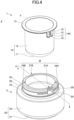
- FIG. 4 is an exploded perspective view of the two-part container 3 according to the first embodiment of the present invention.
- the two-part container 3 includes an inner container 1 and an outer container 2.
- the two-part container 3 as illustrated in FIG. 2 is in a shape of a jar having a wide mouth and a low height, but the two-part container 3 may be in the shape of a vertically long bottle.
- the inner container 1 includes a bottomed cylindrical accommodating portion 10 including a bottom 11 and a side wall 12, an upper-end flange 13 projecting outward from the upper end of the accommodating portion 10, and two hanging portions 14A and 14B hanging from the outer edge of the upper-end flange 13.
- the hanging portions 14A and 14B are tongue-shaped holding pieces for holding the outer container 2 from the outside and engaging with a part of the outer container 2.
- the hanging portions 14A and 14B have openings 16 formed in a hanging surface 15 which is a hanging piece hanging from the outer edge of the upper-end flange 13.
- the hanging portions 14 and 14B are provided with engagement pieces 17 which are claw members that elastically deform within the opening region of the opening 16 when viewed from the outside.
- the inner container 1 is made of, for example, resin or paper.
- the resin forming the inner container 1 is made of, for example, a polyester-based resin such as polypropylene (PP), polyethylene (PE), acrylonitrile butadiene styrene (ABS), polybutylene terephthalate (PBS), polyacetal (POM), polyethylene terephthalate (PET), and resin such as a biodegradable resin.
- the paper forming the inner container 1 is, for example, a laminate made of paper as a base material.
- the outer container 2 is a container-accommodating portion for replaceably casing the inner container 1.
- the outer container 2 includes a case portion 20 including a bottom 21 and a side wall 22.
- a shoulder portion 23 extending inward is provided at the upper end of the case portion 20, and a cylindrical mouth M (see FIG. 4 ) extending upward is provided from an inner edge of the shoulder portion 23.
- the cylindrical mouth M has a diameter smaller than that of the case portion 20 and is located inward of the side wall 22.
- the cylindrical mouth M includes mouth thick-walled portions 24A, 24B, and 24 and mouth thin-walled portions 27A and 27B.
- the cylindrical mouth M is alternately provided with a plurality of mouth thick-walled portions 24A and 24B and mouth thin-walled portions 27A and 27B, the inner surface of which is a continuous circumferential surface and the outer surface of which varies in thickness from the circumferential surface in a stepwise manner.
- the mouth thin-walled portions 27A and 27B are vertically elongated rectangular regions in the cylindrical mouth M.
- Outer surfaces of the mouth thin-walled portions 27A and 27B are partially recessed, extend from the upper end of the cylindrical mouth M, and do not reach the lower end. Therefore, in the cylindrical mouth M, a lower side of an annular projection 26 of the mouth thin-walled portions 27A and 27B is a mouth thick-walled portion 24 having the same thickness as the mouth thick-walled portions 24A and 24B.
- the mouth thick-walled portions 24A and 24B are longer in a circumferential direction than the mouth thin-walled portions 27A and 27B.
- the annular projection 26 extending in the circumferential direction is provided on the entire outer periphery of the cylindrical mouth M.
- a screw projection 25 is provided on the outer peripheral surface of the mouth thick-walled portions 24A and 24B.
- the screw projection 25 is interrupted in the circumferential direction at sections of the mouth thin-walled portions 27A and 27B.
- a lower portion of the annular projection 26 is provided under the mouth thin-walled portions 27A and 27B without being interrupted in the circumferential direction.
- the screw projection 25 may be interrupted in the circumferential direction near the mouth thin-walled portions 27A and 27B (see FIG. 14 ).
- the screw projection 25 is threadedly engaged with a screw projection 43 of a cap 4 (see FIG. 7 ).
- the annular projection 26 is positioned below the screw projection 25, and the cap 4 is engaged so as to cover the annular projection 26.
- the annular projection 26 may also serve as a finger-hook portion on the outer container 2 side for pulling downward when the inner container 1 is pulled out from the outer container 2.
- the mouth thin-walled portions 27A and 27B are each formed with a projection 28 extending in the circumferential direction and a groove 29 positioned below the projection 28.
- the projection 28 provided in the mouth thin-walled portions 27A and 27B may project outwardly on the outer peripheral surface in a stepwise manner at least from the groove 29 immediately below the projection 28. Therefore, the projection 28 need not project from the upper end of the mouth thin-walled portions 27A and 27B above it or from the outer surface of the mouth thin-walled portions 27A and 27B positioned below the groove 29.
- the projection 28 and the groove 29 are used to engage the engagement piece 17 of the hanging portion 14.
- the inner container 1 is a refill that can be replaced (removable and changeable with another) together with its contents, the viscous substance or solid substance. Additionally, the outer container 2 is reused after the refill is replaced.
- the inner container 1 that is empty can be replaced with a new refill of the same shape, and the outer container 2 can be used repeatedly.
- the inner container 1 for replacement that is replaceable as a refill, can cover an upper surface of the upper-end flange 13 with a film F (see FIG. 4 ) or a cover surrounding the upper-end flange 13.
- the inner container 1 serving as a refill can be distributed independently.
- the inner container 1 is provided with the two hanging portions 14A and 14B, but the inner container may include one or more than two hanging portions.
- the number of hanging portions of the inner container is three or more, the number of mouth thin-walled portions provided in the cylindrical mouth M of the outer container is the same as the number of hanging portions.
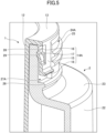
- FIG. 5 is an enlarged sectional perspective view illustrating an engagement between the hanging portion 14A of the inner container 1 and the mouth thin-walled portion 27A of the outer container 2 in the first embodiment.
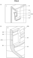
- FIG. 6 (a) is a sectional perspective view of the hanging portion 14A and its surrounding of the inner container 1 according to the first embodiment, and (b) is a sectional perspective view of the mouth thin-walled portion 27A and its surrounding of the outer container 2.
- the engagement piece 17 formed in the hanging portion 14A of the inner container 1 is connected to the lower end of the opening 16, extends upward in a cantilever shape, and is bent such that the upper end is positioned inside (on the inner-diameter side) the lower end.
- the hanging portion 14A which hangs outside the side wall 12 of the inner container 1 faces the mouth thin-walled portion 27A of the outer container 2, and a vicinity of the upper end which is a part of the engagement piece 17 engages with the groove 29 of the mouth thin-walled portion 27A.
- the projection 28 is arranged above the groove 29 which engages with the upper end of the engagement piece 17, the engagement between the outer container 2 and the inner container 1 can be prevented from being released, when a force other than an external force for removal is applied by a user.
- the outer surface (outer-diameter side surface) of the hanging surface 15 of the hanging portion 14 is positioned inside (on the inner-diameter side) the outer surfaces of the mouth thick-walled portions 24A and 24B of the outer container 2. Therefore, when the cap 4 (see FIG. 7 ) and the outer container 2 are relatively rotated so as to be engaged with each other by screwing, the hanging portion 14 does not interfere.
- FIG. 5 is a figure illustrating an example in which the engagement piece 17 formed in the hanging portion 14A of the inner container 1 is connected to the lower end of the opening 16 and extends upward in the cantilever shape, for example, an extending direction of the engagement piece 17 may be upside-down or oblique.
- the upside-down configuration will be described later as a second embodiment together with FIGS. 16 and 17 .
- a free-end side (upper end side) of the cantilever-shaped engagement piece 17 is positioned on the inner-diameter side of the lower end, which is a base (connected end) thereof, and is projected inward. According to this configuration, the upper end of the free-end side of the engagement piece 17 is caught on the projection 28 of the mouth thin-walled portion 27A from the lower side and engaged therewith.
- FIG. 7 is a cross-sectional view of an example of the two-part container 3 engaged with the cap 4.
- the cap 4 includes a top surface 41 and a peripheral wall 42, and a screw projection 43 is provided inside the peripheral wall 42.
- the cap 4 is a lid portion covering the upper-end flange 13 of the inner container 1 and the cylindrical mouth M of the outer container 2, and is made of resin such as PP, PE, ABS, PBS, POM, PET, a polyester resin, or a biodegradable resin.
- a packing 5 as a sealing material for preventing leakage is provided on an inner side (lower side) of the top surface 41 of the cap 4.
- the packing 5 may be adhered to the cap 4, or may be provided separately from the cap 4.
- the packing 5 is made of an elastic rubber or resin (e.g., PP, PE), for example.
- the two-part container when the two-part container is left for a long time with the cap 4 engaged, the contents of the inner container 1 absorb the air inside the container, and the pressure inside of the inner container 1 becomes a negative pressure.
- the two-part container 3 when the two-part container 3 is flown on an airplane with the cap 4 engaged, the pressure inside the inner container 1 becomes the negative pressure after landing due to changes in air pressure.
- the projection 28 is provided above the groove 29 in a mouth thin-walled portion 27 facing the hanging portion 14, the upper end of the engagement piece 17 receives resistance from the projection 28 even when a force is applied to pull the hanging portion 14 upward by suction of the packing 5, and the engagement piece 17 is prevented from climbing over the projection 28, thereby preventing the inner container 1 having the hanging portion 14 from being detached from the outer container 2.
- the engagement piece 17 receives a resistance greater than a predetermined value in both vertical directions by a hand of a user, the engagement piece 17 can be moved by climbing over the projection 28.
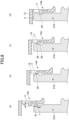
- FIG. 8 is an explanatory view of the state of the engagement piece 17 when the two-part container 3 is assembled and disassembled.
- FIG. 8 (a) is a view illustrating a state where the engagement piece 17 is not in contact with the outer container 2, (b) is a view illustrating a state where the end of the engagement piece 17 is in contact with the projection 28 of the outer container 2, (c) is a view illustrating a state where the end of the engagement piece 17 slides on an inclined surface of the groove 29, and (d) is a view illustrating a state where the engagement piece 17 is engaged with an innermost portion of the groove 29.
- the groove 29 formed in the mouth thin-walled portion 27A of the outer container 2 is a V-groove or a U-groove whose cross section is inclined in the vertical direction toward the innermost portion.
- the groove is a V-shaped or a U-shaped groove and not a rectangular shape whose cross section includes right angles.
- a lateral width (circumferential length) of the groove 29 in the mouth thin-walled portion 27A of the outer container 2 is, for example, about 5 mm to 30 mm, and a length I in the vertical direction of the upper inclined surface or the upper curved surface constituting the groove 29 is about 0.25 mm to 2.5 mm. Therefore, the longitudinal length of the groove 29 is 0.5 mm to 5.0 mm because it is twice the length I of either the inclined or curved surface, and the longitudinal length of the innermost portion of the groove 29 is about 0.5 mm to 3 mm.
- a vertical width W of the projection 28 at the upper end of the mouth thin-walled portion 27A is, for example, about 1 mm to 10 mm.
- the engagement piece 17 provided in the opening region of the opening 16 is elastically deformable when the inner container 1 and the outer container 2 are assembled or disassembled.
- a state of the engagement piece 17 changes in the order of (a) ⁇ (b) ⁇ (c) ⁇ (d) in FIG. 8 .
- the inner-diameter side surface of the end of the free end positioned at the upper end of the engagement piece 17 is positioned radially inward of the inner-diameter side surface of the lower end by a distance d.
- the distance d is, for example, about 5 mm to 15 mm.
- steps change in the order of (d) ⁇ (c) ⁇ (b) ⁇ (a) in FIG. 8 .
- the tip of the engagement piece 17, which is a part of the hanging portion 14A is fitted into the innermost part of the groove 29 and engaged with it.
- the upper end of the engagement piece 17 receives the resistance from the projection 28 during the disengagement of the cap 4, and the engagement piece 17 is prevented from coming off upward from the projection 28.
- the upper end of the engagement piece 17 receives the resistance from the projection 28, even when the user unintentionally holds the portion of the hanging portions 14A and 14B and lifts the two-part container 3, the outer container 2 can be prevented from coming off from the inner container 1.
- the engagement piece 17 can move over the upper inclined side of the groove 29 and the projection 28.
- Such characteristics of the engagement piece 17 make it possible to: make it difficult for the engagement between the inner container 1 and the outer container 2 to be released by the contact between the tip of the engagement piece 17 and the projection 28; and make it difficult for the outer container 2 to be released from the inner container 1, for example, when an unintended force is applied, such as when the packing 5 is attracted or the hanging portion 14A is held and lifted upward. Additionally, according to the characteristics of the engagement piece 17, the engagement can be released by applying a force for separation from both the upper and lower sides while holding both the inner container 1 and the outer container 2.
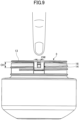
- FIG. 9 is a view for comparing the size of the finger with the size of the opening 16 of the hanging portion 14A.
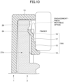
- FIG. 10 is an enlarged cross-sectional view illustrating a state of engagement between the hanging portion 14A of the inner container 1 and the mouth thin-walled portion 27A of the outer container 2 with the hanging portion 14A held with the finger.
- FIG. 10 and subsequent FIGS. 12 , 13 , 16 , and 17 one hanging portion 14A and one mouth thin-walled portion 27A are illustrated, but the hanging portion 14B and the mouth thin-walled portion 27B have the same configuration.
- the width of an average index finger of a Japanese adult near the first joint is about 1.4 cm, and the thumb is thicker than the index finger.
- the movement of the engagement piece 17 with the spring property is not restricted even when the user grips the portion of the hanging portion 14 firmly. Therefore, when a force is applied from both the upper and lower sides by holding both the inner container 1 and the outer container 2 and pull them apart, the engagement piece 17 can slide as illustrated in FIG. 8 and the engagement can be released.
- FIG. 11 is for describing a gripping force applied to the two-part container according to a comparative example.
- FIG. 11 a configuration in which an entire surface of a hanging portion 82 of an inner container 81 is elastically deformed and engaged with a projection 85 of an outer container 84 is illustrated.
- a user applies a force to open a lower end of the hanging portion 82 in an outward direction so as to separate the engagement, while applying a force in a vertical direction to separate the engagement. Therefore, a process of opening the lower end in the outward direction is added during assembly and disassembly.
- the engagement piece 17 that is movable is provided in the opening 16 provided in the hanging portion 14.
- the movement of the engagement piece 17 with the spring property is not restricted due to the space defined in the opening 16, no matter how much "gripping force" is applied from the outside against the hanging portion 14, the pulling force can be kept unaffected. That is, even when the hanging portion is held with a finger as illustrated in FIG. 10 , by applying a force in the vertical direction, that is the direction separating the inner container from the outer container, the engagement piece can be deformed inside the opening and on the inner peripheral side of the finger and the inner container can be pulled out.
- a predetermined resistance is applied to the movement of the tip of the engagement piece 17 by the groove 29 and the projection 28 in the mouth thin-walled portion 27A, so that the engagement state between the inner container 1 and the outer container 2 is not released and the two-part container state is maintained without disassembling by simply gripping and lifting the hanging portions 14A and 14B.
- a predetermined resistance value is provided for the engagement between the tip of the engagement piece 17 and the groove and the projection, and when a force equal to or less than the resistance value is applied without intending to release the engagement, the engagement between the inner container 1 and the outer container 2 is not released, but when a force larger than the resistance value, which is the force for disassembling, is applied, the engagement between the inner container 1 and the outer container 2 can be released without any special additional operation.
- the upper end which is the free end of the engagement piece 17 is bent inward, so that the free-end side of the cantilever-shaped engagement piece 17 is positioned closer to the inner-diameter side than the lower end, which is the base (connected end).
- the free-end side of the engagement piece of the inner container of the present invention is positioned inward as compared to the connected end.
- FIG. 12 is an enlarged cross-sectional view illustrating an engagement state between a hanging portion 14A ⁇ of an inner container 1 ⁇ and a mouth thin-walled portion 27A of an outer container 2 ⁇ of a modified example 1 of the first embodiment.
- an engagement piece 17 ⁇ in the hanging portion 14A ⁇ of the inner container 1 ⁇ is formed by a vertically-extended portion 171 and an upper-end projection 172.
- the vertically-extended portion 171 extends upward from a vicinity of a lower end of the opening 16 of the hanging portion 14A ⁇ in the vertical direction.
- the vertically-extended portion 171 is configured such that its outer-diameter side is thinner than the hanging surface 15.
- the upper-end projection 172 projects inward from an upper end of the vertically-extended portion 171.
- the upper-end projection 172 projecting inward is provided on the upper end, which is the free end of the engagement piece 17 ⁇ , the inner surface of the free end of the cantilever-shaped engagement piece 17 ⁇ is positioned on the inner-diameter side of the lower end, which is the base (connected end), in other words, projected inward.
- the thickness of the engagement piece 17 ⁇ is different between the upper end and the lower end in the configuration of the present modified example, in order to secure a movable space of the engagement piece 17 ⁇ even in a state where the engagement piece is held with a finger, it is preferable that the difference in thickness between the mouth thin-walled portions 27A and 27B and the mouth thick-walled portions 24 ⁇ , 24A ⁇ (not illustrated), and 24B ⁇ (not illustrated) in the cylindrical mouth of the outer container 2 ⁇ is larger than that in the configuration of FIG. 10 .
- FIG. 12 is a figure illustrating an example in which a mouth thick-walled portion 24 ⁇ side is formed thicker than the configuration of FIG. 10 , the thickness on the mouth thin-walled portion 27A side may be formed thinner.
- FIG. 13 is an enlarged cross-sectional view illustrating an engagement between a hanging portion 14A ⁇ of an inner container 1 ⁇ and the mouth thin-walled portion 27A of the outer container 2 ⁇ in a modified example 2 of the first embodiment.
- an engagement piece 17 ⁇ in the hanging portion 14A ⁇ of the inner container 1 ⁇ is formed of the vertically-extended portion 171, a variable-thickness portion 173, and an upper-end projection 172 ⁇ .
- the vertically-extended portion 171 of the engagement piece 17 ⁇ in the present modified example has the same configuration as that in FIG. 12 , but the thickness of the variable-thickness portion 173 gradually increases from the bottom to the top of the engagement piece 17 ⁇ and the variable-thickness portion 173 is connected to the upper-end projection 172 ⁇ .
- the upper-end projection 172 ⁇ projecting inwardly is provided at the upper end, which is the free end of the engagement piece 17 ⁇
- the inner surface of the free end of the cantilever-shaped engagement piece 17 ⁇ is located on the inner-diameter side of the lower end, which is the base (connected end), and is projected inward.
- the thickness of the hanging portion 17A ⁇ varies at the upper and lower ends of the engagement piece 17 ⁇ , and the thicknesses are different at the upper and lower ends. Therefore, in order to secure the movable space of the engagement piece 17 ⁇ even in the state of being held with a finger as in the modified example 1, it is preferable that the difference in thickness between the mouth thin-walled portions 27A, 27B and the mouth thick-walled portions 24 ⁇ , 24A ⁇ , 24B ⁇ in the cylindrical mouth of the outer container 2 ⁇ is larger than that of the configuration as illustrated in FIG. 10 .
- FIG. 13 is a figure illustrating an example in which the thickness on the mouth thick-walled portion 24 ⁇ side is thicker than that of the configuration as illustrated in FIG. 10 , the thickness on the mouth thin-walled portion 27A side may be thinner.
- FIG. 14 is an exploded front view of the two-part container according to a modified example 3 of the first embodiment.
- FIG. 15 is an enlarged sectional view illustrating a state of engagement between the hanging portion of the inner container of FIG. 14 engaged with the cap and the mouth thin-walled portion of the outer container.
- one hanging portion there may be one hanging portion.
- widths in the circumferential direction of the single hanging portion 14 ⁇ and the mouth thin-walled portion 27 ⁇ opposed thereto can be made wider than when there are a plurality of hanging portions.
- the opening 16 surrounding the engagement piece 17 has an elongated rectangular shape, and the lateral width OW is 1 cm or less, more preferably 0.7 cm or less, and the longitudinal length OH is 1 to 2 cm.
- a screw projection 25 ⁇ provided on an outer circumferential surface of the mouth thick-walled portion 24 ⁇ may be interrupted in the vicinity of the mouth thin-walled portion 27 ⁇ without reaching the mouth thin-walled portion.
- the screw projection 43 which is a female screw of the cap 4 to be engaged with the screw projection 25 ⁇ , is provided without discontinuity in the circumferential direction, the cap 4 and the cylindrical mouth M ⁇ of the outer container 2 ⁇ can be screwed into and threadedly engaged with each other without any problem even when the screw projection 25 is broken in the outer container 2 ⁇ .
- a vertical rib 121 is provided on the outside of a side wall 12 ⁇ of an accommodating portion 10 ⁇ of an inner container 1 ⁇ .
- a space G is provided between an outside surface of the side wall 12 ⁇ of the accommodating portion 10 ⁇ of the inner container 1 ⁇ and the inside surface of the cylindrical mouth M ⁇ of the outer container 2 ⁇ . In this way, an area of adhesion between the inner container 1 ⁇ and the outer container 2 ⁇ on a side surface can be reduced, thereby preventing excessive adhesion.
- annular rib 131 is provided on an upper surface of an upper-end flange 13 ⁇ of the inner container 1 ⁇ .
- the packing 5 ⁇ is arranged on the annular rib 131, and when the packing 5 ⁇ comes into close contact with the upper-end flange 13 ⁇ , the annular rib 131 fits into the packing 5 ⁇ .
- FIG. 16 (a) is a sectional perspective view in the vicinity of a hanging portion 140A of an inner container 1 ⁇ according to the second embodiment, and (b) is a sectional perspective view in the vicinity of a mouth thin-walled portion 270A of an outer container 2 ⁇ according to the second embodiment.
- FIG. 17 is an enlarged sectional view illustrating a state of engagement between the hanging portion 140A of the inner container 1 ⁇ according to the second embodiment and the mouth thin-walled portion 270A of the outer container ⁇ . Only differences from the first embodiment will be described.
- an engagement piece 170 of the inner container 1 ⁇ extends downward in a cantilever shape so that the upper end thereof is connected to the vicinity of the upper end of an opening 160 in a hanging surface 150 of the hanging portion 140A and a lower end thereof is a free end thereof, and a lower end thereof is bent so as to be positioned on an inner-diameter side of an upper end thereof.
- the engagement piece 170 according to the present embodiment is vertically opposite to the extending direction of the engagement piece 17 according to the first embodiment.
- a projection 280 to which the inner surface of the lower end, that is the free end, of the engagement piece 170 contacts, and a groove 290 into which the free end is fitted into at the time of engagement, are positioned on lower than the positions in the first embodiment.
- the engagement piece 170 extends downward in a cantilever shape, and since the lower end is bent so as to be positioned on the inner-diameter side of the upper end, the inner surface of the lower end, which is the free end, is positioned on the inner side of the upper end, which is the base (connected end), and is projected inward.
- a width and a vertical width of the opening 160 in the hanging portion 140A are both less than 1 cm. Therefore, in a state where the finger does not enter the inside of the opening 160, the engagement piece 170 will not be unintentionally moved in an opening space defined by the opening 160 when the engagement is not intended to be released.
- the engagement piece 170 since the lower end of the free-end side of the engagement piece 170 is caught (contacts) on the lower side of the projection 280 of the mouth thin-walled portion 270A, the engagement between the inner container 1 ⁇ and the outer container 2 ⁇ is unlikely to be released when the engagement is not intended to be released, and the inner container 1 ⁇ can be prevented from being detached from the outer container 2 ⁇ .
- the engagement piece 170 is movably provided in the opening 160 provided in the hanging portion 140A.
- the movement of the engagement piece 170 with the spring property is not restricted due to the space defined by the opening 160, no matter how much "gripping force" is applied from the outside against the hanging portion 140A, the pulling force can be kept unaffected. That is, even when the hanging portion is held with a finger, by applying a force in the vertical direction, that is the direction separating the inner container 1 ⁇ from the outer container 2 ⁇ , the engagement piece 170 is deformed inside the opening 160 on the inner peripheral side of the finger and the inner container 1 ⁇ can be pulled out.
- the engagement piece 170 as illustrated in FIG. 17 has a configuration in which the upper end, which is a free end, is bent inward, so that the free-end side of the cantilever-shaped engagement piece 170 is positioned inward from the lower end, which is a base (connected end).
- the engagement piece 170 may also have a configuration in which the free-end side projects inward from the coupling end due to another shape.
- the engagement piece in the engagement piece cantilevered and extended downward from the top as in the second embodiment, may be configured to include a linearly-hanging hanging piece and a projection projecting inward to the lower side, which is the free end of the hanging piece, as in a configuration obtained by reversing the configuration of the engagement piece 17 ⁇ in the modified example 1 as illustrated in FIG. 12 .
- the engagement piece may be configured to include a hanging piece whose thickness varies in a stepwise manner, as in a configuration obtained by reversing the engagement piece 17 ⁇ in the modified example 2 as illustrated in FIG. 13 .
- the engagement piece in the hanging portion is cantilevered and extends upward from the bottom, and in the second embodiment, the engagement piece extends downward from the top, but the extending direction of the engagement piece 17 may be oblique.
- FIG. 7 is a figure illustrating an example in which the cap 4 is threadedly engaged with the outer container 2, the cap 4 need not be threadedly engaged and thus may be a push-in type.
- the outer container 2 may be provided with the projection 28 extending in the circumferential direction and the groove 29 positioned below the projection in the entire area on the outer surface without providing a screw projection.
- the inner container 1 need not be partially provided with a plurality of hanging portions, and a cylindrical hanging cylinder may be provided around the entire outer edge of the upper-end flange 13 .
- the hanging cylinder is provided with one or more openings, and the engagement pieces, of the number equal to that of the openings, located on the inner side of the openings.
Landscapes
- Engineering & Computer Science (AREA)
- Mechanical Engineering (AREA)
- Ceramic Engineering (AREA)
- Food Science & Technology (AREA)
- Closures For Containers (AREA)
Abstract
Description
- The present invention relates to a two-part container and a cap-equipped two-part container.
- In recent years, from the viewpoint of reducing resin, two-part containers composed of an outer container that can be used repeatedly and a replaceable refill (inner container) have been increasing.
- As a technique for using an inner side of a jar container as a refill container, the jar container being provided with a wide mouth for storing viscous substances such as cosmetics and pharmaceuticals, a configuration in which an outer container is held from an outer side by a holding piece (hanging piece) that extends outward from an upper end of an inner container and hangs downward around the mouth is known. As an example, as illustrated in
FIG. 1 ,Patent Document 1 discloses a configuration in which a tongue-shaped notch 94 is formed at an upper end of anouter container 92, ahanging piece 93 with a spring property hanging down from an outside of an upper end of aninner container 91 covers thenotch 94, and an engaging portion 931 at a lower end of the hangingpiece 93 engages anengaging portion 941 located in a bottom portion of thenotch 94. - Patent Document 1:
Japanese Patent No. 6448471 - However, in the configuration of
Patent Document 1, since thenotch 94 is formed in theouter container 92, theouter container 92 cannot be formed with glass, and the material that can be used is limited. - Further, in the configuration of
Patent Document 1, when a user grips thehanging piece 93 from the outside, an engagement state of theengaging portions 931 and 941 is released when lifted, and there is a possibility that theinner container 91 may become disengaged from theouter container 92. - In view of the above, the present invention provides a two-part container without limiting the material of the outer container, and wherein an engagement between the inner container and the outer container is unlikely to be released when the engagement is not intended to be released.
- To solve the above problem, according to one aspect of the present invention, provided is a two-part container including:
- an outer container; and
- an inner container, wherein
- the outer container includes a projection formed on an outer surface of a mouth thereof and extends in a circumferential direction,
- the inner container includes an accommodating portion configured to accommodate contents, an upper-end flange that extends outward from an upper end of the accommodating portion, and a hanging portion that hangs downward from an outer edge end of the upper-end flange,
- an opening is formed in the hanging portion, and the hanging portion includes an engagement piece that elastically deforms within an opening region of the opening in a view from an outer surface of the hanging portion, and
- a part of the engagement piece contacts a lower surface of the projection, thereby preventing engagement between the outer container and the inner container from being released, upon attachment of the inner container to the outer container.
- According to one aspect, in the two-part container, the material of the outer container is not limited, and the engagement between the inner container and the outer container can be made difficult to be released when the engagement is not intended to be released.
-
- [
FIG. 1] FIG. 1 is an exploded perspective view of a two-part container of a related-art example. - [
FIG. 2] FIG. 2 is a cross-sectional view of a two-part container of a first embodiment. - [
FIG. 3] FIG. 3 is a perspective view of the two-part container of the first embodiment. - [
FIG. 4] FIG. 4 is an exploded perspective view of the two-part container of the first embodiment. - [
FIG. 5] FIG. 5 is an enlarged cross-sectional perspective view illustrating a state of engagement between a hanging portion of an inner container and a mouth thin-walled portion of the outer-container of the first embodiment. - [
FIG. 6] FIG. 6 is a cross-sectional perspective view near the hanging portion of the inner container and a cross-sectional perspective view near the mouth thin-walled portion of the outer-container according to the first embodiment. - [
FIG. 7] FIG. 7 is a cross-sectional view of the two-part container of the first embodiment engaged with a cap. - [
FIG. 8] FIG. 8 is an explanatory view of deformation of the engagement piece during assembly and disassembly of the two-part container of the first embodiment. - [
FIG. 9] FIG. 9 is a view for comparing the size of the finger with the opening of the hanging portion. - [
FIG. 10] FIG. 10 is an enlarged cross-sectional view illustrating the state of the engagement between the hanging portion of the inner container and the mouth thin-walled portion of the outer container, when gripping of the hanging portion of the first embodiment is performed with fingers. - [
FIG. 11] FIG. 11 is a view illustrating a gripping force applied to the two-part container according to a comparative example. - [
FIG. 12] FIG. 12 is an enlarged cross-sectional view illustrating a state of engagement between the hanging portion of the inner container and the mouth thin-walled portion of the outer container, of modified example 1 of the first embodiment. - [
FIG. 13] FIG. 13 is an enlarged cross-sectional view illustrating the state of engagement between the hanging portion of the inner container and the mouth thin-walled portion of the outer container, of modified example 2 of the first embodiment. - [
FIG. 14] FIG. 14 is an exploded front view of the two-part container of modified example 3 of the first embodiment. - [
FIG. 15] FIG. 15 is an enlarged sectional view illustrating the state of engagement between the hanging portion of the inner container and the mouth thin-walled portion of the outer container ofFIG. 14 engaged with the cap. - [
FIG. 16] FIG. 16 is a sectional perspective view of a vicinity of a hanging portion of an inner container and a sectional perspective view of a vicinity of a mouth thin-walled portion of an outer container according to a second embodiment of the present invention. - [
FIG. 17] FIG. 17 is an enlarged sectional view illustrating the state of engagement between the hanging portion of the inner container and the mouth thin-walled portion of the outer container according to the second embodiment. - Hereinafter, an embodiment for carrying out the present invention will be described with reference to the drawings. In the following drawings, the same components are denoted by the same reference numerals, and redundant descriptions may be omitted.
- The present invention relates to a two-part container, particularly to a two-part container for casing a viscous substance or a solid substance. The inner container of the two-part container is made of resin or paper and may be self-standing or non-self-standing. The outer container of the two-part container is a self-standing container made of glass, wood, resin, silicone, metal, or the like.
- The contents to be contained in the inner container held by the outer container of the two-part container of the present invention are preferably viscous or solid substances such as cosmetics, perfumes, detergents, seasonings, and the like, which are not used up at once but are used in multiple times.
- In the present specification, the viscous substances are viscous cosmetics, viscous medicines, viscous soaps, and the like, such as creams, hair waxes, and ointments. The solid substances are solid cosmetics such as hair styling sticks, hair waxes, solid beauty serums (e.g., similar in hardness to a stick serum) and the like, which are particularly hard, or semi-solid cosmetics, solid soaps, cheese, butter, and the like.
- In the present invention, the viscous substances or the solid substances are originally filled into the accommodating portion, and replenished by replacing the inner container itself with a refill (refill container).
- First, the overall configuration of a two-part container according to a first embodiment of the present invention will be described with reference to
FIGS. 2 to 4 .FIG. 2 is a cross-sectional view of a two-part container 3 according to the first embodiment of the present invention.FIG. 3 is a perspective view of the two-part container 3 according to the first embodiment of the present invention.FIG. 2 corresponds to a cross-sectional view on a plane A ofFIG. 3 .FIG. 4 is an exploded perspective view of the two-part container 3 according to the first embodiment of the present invention. - The two-
part container 3 according to the present invention includes aninner container 1 and anouter container 2. The two-part container 3 as illustrated inFIG. 2 is in a shape of a jar having a wide mouth and a low height, but the two-part container 3 may be in the shape of a vertically long bottle. - In the present embodiment, the
inner container 1 includes a bottomed cylindricalaccommodating portion 10 including abottom 11 and aside wall 12, an upper-end flange 13 projecting outward from the upper end of theaccommodating portion 10, and two hangingportions end flange 13. - The hanging
portions outer container 2 from the outside and engaging with a part of theouter container 2. The hangingportions openings 16 formed in a hangingsurface 15 which is a hanging piece hanging from the outer edge of the upper-end flange 13. In addition, the hangingportions engagement pieces 17 which are claw members that elastically deform within the opening region of the opening 16 when viewed from the outside. - At the lower end of the hanging
surface 15 of a hangingportion 14, a lower-end projection 18 projecting upward is provided. The lower-end projection 18 serves as a finger-hook portion on aninner container 1 side when pulling out theinner container 1 from theouter container 2. Alternatively, when it is too tight to be pulled out due to, for example, a change in an internal pressure, the lower-end projection 18 may be used as an aid for lifting when pulling out, by inserting a coin or the like into a gap on a lower side of the lower-end projection 18 and pushing it up. - The
inner container 1 is made of, for example, resin or paper. The resin forming theinner container 1 is made of, for example, a polyester-based resin such as polypropylene (PP), polyethylene (PE), acrylonitrile butadiene styrene (ABS), polybutylene terephthalate (PBS), polyacetal (POM), polyethylene terephthalate (PET), and resin such as a biodegradable resin. Alternatively, the paper forming theinner container 1 is, for example, a laminate made of paper as a base material. - The
outer container 2 is a container-accommodating portion for replaceably casing theinner container 1. Theouter container 2 includes acase portion 20 including a bottom 21 and aside wall 22. In theouter container 2, ashoulder portion 23 extending inward is provided at the upper end of thecase portion 20, and a cylindrical mouth M (seeFIG. 4 ) extending upward is provided from an inner edge of theshoulder portion 23. As illustrated inFIG. 2 , the cylindrical mouth M has a diameter smaller than that of thecase portion 20 and is located inward of theside wall 22. - The cylindrical mouth M includes mouth thick-
walled portions walled portions FIG. 4 , the cylindrical mouth M is alternately provided with a plurality of mouth thick-walled portions walled portions walled portions walled portions annular projection 26 of the mouth thin-walled portions walled portion 24 having the same thickness as the mouth thick-walled portions - In the cylindrical mouth M, the mouth thick-
walled portions walled portions annular projection 26 extending in the circumferential direction is provided on the entire outer periphery of the cylindrical mouth M.A screw projection 25 is provided on the outer peripheral surface of the mouth thick-walled portions screw projection 25 is interrupted in the circumferential direction at sections of the mouth thin-walled portions annular projection 26 is provided under the mouth thin-walled portions screw projection 25 may be interrupted in the circumferential direction near the mouth thin-walled portions FIG. 14 ). - The
screw projection 25 is threadedly engaged with ascrew projection 43 of a cap 4 (seeFIG. 7 ). Theannular projection 26 is positioned below thescrew projection 25, and thecap 4 is engaged so as to cover theannular projection 26. Theannular projection 26 may also serve as a finger-hook portion on theouter container 2 side for pulling downward when theinner container 1 is pulled out from theouter container 2. - The mouth thin-
walled portions projection 28 extending in the circumferential direction and agroove 29 positioned below theprojection 28. Theprojection 28 provided in the mouth thin-walled portions groove 29 immediately below theprojection 28. Therefore, theprojection 28 need not project from the upper end of the mouth thin-walled portions walled portions groove 29. Theprojection 28 and thegroove 29 are used to engage theengagement piece 17 of the hangingportion 14. - Since the
outer container 2 of the present invention does not have an intermittent portion such as a cutout in the related-art example, it can be molded of various materials without limitation of materials. For example, theouter container 2 can be made of resin, glass, wood, silicone, metal, paper, or the like. In the case of resin, for example, like theinner container 1 described above, theouter container 2 is made of resin such as PP, PE, ABS, PBS, POM, PET, polyester resin, or biodegradable resin. In the case of wood, for example, coniferous wood such as cedar, cypress, and pine, broadleaf wood such as oak, walnut, black cherry, elder, and rubberwood, and bamboo are included. In the case of paper, for example, theouter container 2 is self-standing cardboard. - Here, as illustrated in the exploded view of
FIG. 4 , theinner container 1 is a refill that can be replaced (removable and changeable with another) together with its contents, the viscous substance or solid substance. Additionally, theouter container 2 is reused after the refill is replaced. - Therefore, the
inner container 1 that is empty can be replaced with a new refill of the same shape, and theouter container 2 can be used repeatedly. - The
inner container 1 for replacement, that is replaceable as a refill, can cover an upper surface of the upper-end flange 13 with a film F (seeFIG. 4 ) or a cover surrounding the upper-end flange 13. Thus, theinner container 1 serving as a refill can be distributed independently. - In the examples illustrated in
FIGS. 2 to 4 , theinner container 1 is provided with the two hangingportions - Next, the configuration and engagement of the hanging portion and the mouth thin-walled portion in the first embodiment will be described with reference to
FIGS. 5 and6 .FIG. 5 is an enlarged sectional perspective view illustrating an engagement between the hangingportion 14A of theinner container 1 and the mouth thin-walled portion 27A of theouter container 2 in the first embodiment. InFIG. 6 , (a) is a sectional perspective view of the hangingportion 14A and its surrounding of theinner container 1 according to the first embodiment, and (b) is a sectional perspective view of the mouth thin-walled portion 27A and its surrounding of theouter container 2. - As illustrated in
FIGS. 5 and6 , in the configuration of the first embodiment, theengagement piece 17 formed in the hangingportion 14A of theinner container 1 is connected to the lower end of theopening 16, extends upward in a cantilever shape, and is bent such that the upper end is positioned inside (on the inner-diameter side) the lower end. - Therefore, as illustrated in
FIG. 5 , when theinner container 1 is mounted on theouter container 2, the hangingportion 14A which hangs outside theside wall 12 of theinner container 1 faces the mouth thin-walled portion 27A of theouter container 2, and a vicinity of the upper end which is a part of theengagement piece 17 engages with thegroove 29 of the mouth thin-walled portion 27A. - Further, since the
projection 28 is arranged above thegroove 29 which engages with the upper end of theengagement piece 17, the engagement between theouter container 2 and theinner container 1 can be prevented from being released, when a force other than an external force for removal is applied by a user. - Also, as illustrated in
FIG. 5 , in an engaged state, the outer surface (outer-diameter side surface) of the hangingsurface 15 of the hangingportion 14 is positioned inside (on the inner-diameter side) the outer surfaces of the mouth thick-walled portions outer container 2. Therefore, when the cap 4 (seeFIG. 7 ) and theouter container 2 are relatively rotated so as to be engaged with each other by screwing, the hangingportion 14 does not interfere. - Although
FIG. 5 is a figure illustrating an example in which theengagement piece 17 formed in the hangingportion 14A of theinner container 1 is connected to the lower end of theopening 16 and extends upward in the cantilever shape, for example, an extending direction of theengagement piece 17 may be upside-down or oblique. The upside-down configuration will be described later as a second embodiment together withFIGS. 16 and17 . - Further, in the configuration of the present embodiment, since the upper end of the
engagement piece 17, which is the free end thereof, is bent inward, a free-end side (upper end side) of the cantilever-shapedengagement piece 17 is positioned on the inner-diameter side of the lower end, which is a base (connected end) thereof, and is projected inward. According to this configuration, the upper end of the free-end side of theengagement piece 17 is caught on theprojection 28 of the mouth thin-walled portion 27A from the lower side and engaged therewith. Therefore, even when it is not intended to release the engagement, for example, when the two-part container 3 is lifted while the vicinity of theengagement piece 17 is pushed from the outer-diameter side, or when opening the cap, which will be described later, it is unlikely that the engagement between theinner container 1 and theouter container 2 will become released, and thus theinner container 1 can be prevented from being detached from theouter container 2. - The two-
part container 3 of the present invention can be engaged with a cap.FIG. 7 is a cross-sectional view of an example of the two-part container 3 engaged with thecap 4. - The
cap 4 includes atop surface 41 and aperipheral wall 42, and ascrew projection 43 is provided inside theperipheral wall 42. - The
cap 4 is a lid portion covering the upper-end flange 13 of theinner container 1 and the cylindrical mouth M of theouter container 2, and is made of resin such as PP, PE, ABS, PBS, POM, PET, a polyester resin, or a biodegradable resin. - A packing 5 as a sealing material for preventing leakage is provided on an inner side (lower side) of the
top surface 41 of thecap 4. Thepacking 5 may be adhered to thecap 4, or may be provided separately from thecap 4. Thepacking 5 is made of an elastic rubber or resin (e.g., PP, PE), for example. - When the
cap 4 is engaged with the two-part container 3, thescrew projection 25 of the cylindrical mouth M of theouter container 2 and thescrew projection 43 of thecap 4 are threadedly engaged with each other. At this time, thepacking 5 is engaged between the lower surface of thetop surface 41 of thecap 4 and the upper-end flange 13 of theinner container 1. - When the
cap 4 and the two-part container 3 are engaged with theelastic packing 5 in between, the contents do not leak out even when the two-part container 3 is tilted or turned upside down. - However, when the two-part container is left for a long time with the
cap 4 engaged, the contents of theinner container 1 absorb the air inside the container, and the pressure inside of theinner container 1 becomes a negative pressure. Alternatively, when the two-part container 3 is flown on an airplane with thecap 4 engaged, the pressure inside theinner container 1 becomes the negative pressure after landing due to changes in air pressure. - Due to the above circumstances, when the pressure inside the
inner container 1 becomes the negative pressure, thepacking 5 is strongly adsorbed to the upper-end flange 13 side. In this state, when the engagement between the two-part container 3 and thecap 4 is released, a force is applied in the direction in which theinner container 1 is detached from theouter container 2 due to the adsorption of thepacking 5. - However, according to the configuration of the present invention, since the
projection 28 is provided above thegroove 29 in a mouth thin-walled portion 27 facing the hangingportion 14, the upper end of theengagement piece 17 receives resistance from theprojection 28 even when a force is applied to pull the hangingportion 14 upward by suction of thepacking 5, and theengagement piece 17 is prevented from climbing over theprojection 28, thereby preventing theinner container 1 having the hangingportion 14 from being detached from theouter container 2. - Furthermore, the
engagement piece 17 receives a resistance greater than a predetermined value in both vertical directions by a hand of a user, theengagement piece 17 can be moved by climbing over theprojection 28. - Now, the behavior of the
engagement piece 17 during attachment (assembly) and detachment (disassembly) of the inner container from the outer container according to the first embodiment will be described with reference toFIGS. 5 ,6 , and8. FIG. 8 is an explanatory view of the state of theengagement piece 17 when the two-part container 3 is assembled and disassembled. - In
FIG. 8 , (a) is a view illustrating a state where theengagement piece 17 is not in contact with theouter container 2, (b) is a view illustrating a state where the end of theengagement piece 17 is in contact with theprojection 28 of theouter container 2, (c) is a view illustrating a state where the end of theengagement piece 17 slides on an inclined surface of thegroove 29, and (d) is a view illustrating a state where theengagement piece 17 is engaged with an innermost portion of thegroove 29. - As illustrated in
FIG. 8 , thegroove 29 formed in the mouth thin-walled portion 27A of theouter container 2 is a V-groove or a U-groove whose cross section is inclined in the vertical direction toward the innermost portion. As illustrated inFIG. 8 (c) , since a tip of theengagement piece 17 slides on an upper inclined surface or curved surface of the groove, it is preferable that the groove is a V-shaped or a U-shaped groove and not a rectangular shape whose cross section includes right angles. - A lateral width (circumferential length) of the
groove 29 in the mouth thin-walled portion 27A of theouter container 2 is, for example, about 5 mm to 30 mm, and a length I in the vertical direction of the upper inclined surface or the upper curved surface constituting thegroove 29 is about 0.25 mm to 2.5 mm. Therefore, the longitudinal length of thegroove 29 is 0.5 mm to 5.0 mm because it is twice the length I of either the inclined or curved surface, and the longitudinal length of the innermost portion of thegroove 29 is about 0.5 mm to 3 mm. A vertical width W of theprojection 28 at the upper end of the mouth thin-walled portion 27A is, for example, about 1 mm to 10 mm. - In the hanging
portion 14A, theengagement piece 17 provided in the opening region of theopening 16 is elastically deformable when theinner container 1 and theouter container 2 are assembled or disassembled. - During assembly, a state of the
engagement piece 17 changes in the order of (a) → (b) → (c) → (d) inFIG. 8 . As illustrated inFIG. 8 (a) , when theengagement piece 17 is in a non-contact state and no force is applied, the inner-diameter side surface of the end of the free end positioned at the upper end of theengagement piece 17 is positioned radially inward of the inner-diameter side surface of the lower end by a distance d. The distance d is, for example, about 5 mm to 15 mm. - Then, when the position of the
inner container 1 is lowered by pushing it downward with respect to theouter container 2 as illustrated inFIG. 8 (a) →FIG. 8 (b) , theengagement piece 17 moves radially outward in an opening space formed by theopening 16 while the tip thereof is deformed by contacting theprojection 28. At this time, since the upper end of theengagement piece 17 passes over an upper-end corner of the mouth thin-walled portion 27A indicated by "o" inFIG. 8 (b) , a resistive force is generated in the movement ofFIG. 8 (a) →FIG. 8 (b) , and thus a user must push theinner container 1 downward with a force of a predetermined strength or stronger. - Further, when the
inner container 1 is pushed downward with respect to theouter container 2, as illustrated inFIG. 8 (b) →FIG. 8 (c) , theengagement piece 17 moves downward while moving toward an inner side (inner-diameter side) of thegroove 29, in a state the tip thereof is deformed by contacting an upper inclined side of thegroove 29 and moved outward (outer-diameter side) in the opening space formed by theopening 16. - Then, when the
inner container 1 is pushed to the lowest end with respect to theouter container 2, as illustrated inFIG. 8 (c) → FIG. 8 (d) , the upper-end flange 13 is brought close to an upper end U of the cylindrical mouth M of theouter container 2, and the tip of theengagement piece 17 fits into the innermost portion of thegroove 29. As a result, theengagement piece 17, which is a part of the hangingportion 14A, is engaged with thegroove 29. - Furthermore, at the time of removal, steps change in the order of (d) → (c) → (b) → (a) in
FIG. 8 . As illustrated inFIG. 8 (d) , in the engaged state, the tip of theengagement piece 17, which is a part of the hangingportion 14A, is fitted into the innermost part of thegroove 29 and engaged with it. - As illustrated in
FIG. 8 (d) →FIG. 8 (c) , when the position of theinner container 1 is raised by pushing it upward with respect to theouter container 2, theengagement piece 17 moves outward in the opening space formed by theopening 16 while the tip (upper end) is deformed by contacting the upper inclined side of thegroove 29. - Furthermore, when the
inner container 1 is pushed upward with respect to theouter container 2, as illustrated inFIG. 8 (c) →FIG. 8 (b) , theengagement piece 17 moves in contact with the outer surface of theprojection 28 while crossing a boundary between the upper inclined side of thegroove 29 and theprojection 28, in a state where the tip is pushed and moved outward in the open space formed by theopening 16. - Here, when the upper end of the
engagement piece 17 moves from the state as illustrated inFIG. 8 (d) →FIG. 8 (c) , theengagement piece 17 deforms elastically and a resistive force is required to climb up the upper inclined side of thegroove 29 while receiving a force. Further, in a transition from the state as illustrated inFIG. 8 (c) →FIG. 8 (b) , the resistive force is required such that theengagement piece 17 is elastically deformed in the direction it further deforms and passes over the boundary with theprojection 28 after climbing up the upper inclined side of thegroove 29 while receiving a force. - Therefore, even when a force is applied to pull the hanging
portion 14 upward due to the adsorption of thepacking 5 due to the passage of time or a change in air pressure caused by an airplane, the upper end of theengagement piece 17 receives the resistance from theprojection 28 during the disengagement of thecap 4, and theengagement piece 17 is prevented from coming off upward from theprojection 28. Alternatively, since the upper end of theengagement piece 17 receives the resistance from theprojection 28, even when the user unintentionally holds the portion of the hangingportions part container 3, theouter container 2 can be prevented from coming off from theinner container 1. - On the other hand, when the user pulls the
inner container 1 upward and theouter container 2 downward for the purpose of disassembling the two-part container 3 and applies a force equal to or greater than a predetermined force, theengagement piece 17 can move over the upper inclined side of thegroove 29 and theprojection 28. - Furthermore, when the
inner container 1 is pushed upward with respect to theouter container 2, as illustrated inFIG. 8 (b) →FIG. 8 (a) , theengagement piece 17 moves while contacting the outer surface of theprojection 28, and then becomes to be in a non-contact state. Accordingly, the contact between the hangingportion 14A and the mouth thin-walled portion 27A is released, and thus the engagement is released. - Such characteristics of the
engagement piece 17 make it possible to: make it difficult for the engagement between theinner container 1 and theouter container 2 to be released by the contact between the tip of theengagement piece 17 and theprojection 28; and make it difficult for theouter container 2 to be released from theinner container 1, for example, when an unintended force is applied, such as when thepacking 5 is attracted or the hangingportion 14A is held and lifted upward. Additionally, according to the characteristics of theengagement piece 17, the engagement can be released by applying a force for separation from both the upper and lower sides while holding both theinner container 1 and theouter container 2. - Hereinafter, the sizes of the user's finger and the
opening 16 of the hangingportion 14 will be described with reference toFIGS. 9 and10 .FIG. 9 is a view for comparing the size of the finger with the size of theopening 16 of the hangingportion 14A.FIG. 10 is an enlarged cross-sectional view illustrating a state of engagement between the hangingportion 14A of theinner container 1 and the mouth thin-walled portion 27A of theouter container 2 with the hangingportion 14A held with the finger. InFIG. 10 and subsequentFIGS. 12 ,13 ,16 , and17 , one hangingportion 14A and one mouth thin-walled portion 27A are illustrated, but the hangingportion 14B and the mouth thin-walled portion 27B have the same configuration. - As described above, in the hanging
portion 14A, theopening 16 surrounding theengagement piece 17 has an elongated rectangular shape, and a lateral width OW is 1 cm or less, more preferably 0.7 cm or less, and a longitudinal length OH is 1 to 2 cm. - In contrast to this, as an example, the width of an average index finger of a Japanese adult near the first joint is about 1.4 cm, and the thumb is thicker than the index finger.
- Thus, even when a user grips the portion of the hanging
portion 14 with his or her finger, the width of the index finger is thicker than the width OW of theopening 16, and the finger is prevented from directly touching theengagement piece 17 located inside theopening 16. - Therefore, as illustrated in
FIG. 10 , in a state where the finger does not enter the inside of theopening 16, touching of the hangingportion 14 without user's intention to release the engagement, for example, when opening or closing the cap, and unintentionally moving the theengagement piece 17 in the opening space defined by theopening 16 do not occur. Therefore, a constant resistance can be continuously provided by the contact between the tip of theengagement piece 17 in the hangingportion 14 and theprojection 28 of the mouth thin-walled portion 27A, and the engagement between theinner container 1 and theouter container 2 can be made difficult to be released. - In addition to the above, when the user intends to release the engagement in order to disassemble the two-
part container 3, the movement of theengagement piece 17 with the spring property is not restricted even when the user grips the portion of the hangingportion 14 firmly. Therefore, when a force is applied from both the upper and lower sides by holding both theinner container 1 and theouter container 2 and pull them apart, theengagement piece 17 can slide as illustrated inFIG. 8 and the engagement can be released. -
FIG. 11 is for describing a gripping force applied to the two-part container according to a comparative example. InFIG. 11 , a configuration in which an entire surface of a hangingportion 82 of aninner container 81 is elastically deformed and engaged with aprojection 85 of anouter container 84 is illustrated. - In the configuration of this comparative example, since the entire surface of the hanging
portion 82 provided with the engagingprojection 83 at an inner lower end is elastically deformed like a spring, when the hangingportion 82 is pushed in from the outside, an engagement becomes stronger, and theouter container 84 cannot be pulled out from theinner container 81 when a two-part container X is disassembled. - Therefore, in the comparative example of
FIG. 11 , at the time of disassembling the two-part container X, a user applies a force to open a lower end of the hangingportion 82 in an outward direction so as to separate the engagement, while applying a force in a vertical direction to separate the engagement. Therefore, a process of opening the lower end in the outward direction is added during assembly and disassembly. - In contrast, in the configuration of the present invention, the
engagement piece 17 that is movable is provided in theopening 16 provided in the hangingportion 14. Thus, since the movement of theengagement piece 17 with the spring property is not restricted due to the space defined in theopening 16, no matter how much "gripping force" is applied from the outside against the hangingportion 14, the pulling force can be kept unaffected. That is, even when the hanging portion is held with a finger as illustrated inFIG. 10 , by applying a force in the vertical direction, that is the direction separating the inner container from the outer container, the engagement piece can be deformed inside the opening and on the inner peripheral side of the finger and the inner container can be pulled out. - Therefore, at the time of assembly or removal, there is no need to additionally perform a process of opening the hanging portion as in the comparative example, and the engagement can be released by applying a force for separation from both the upper and lower sides while holding both the
inner container 1 and theouter container 2. - Further, as illustrated in
FIG. 8 (d) andFIG. 10 , at the time of engagement, a predetermined resistance is applied to the movement of the tip of theengagement piece 17 by thegroove 29 and theprojection 28 in the mouth thin-walled portion 27A, so that the engagement state between theinner container 1 and theouter container 2 is not released and the two-part container state is maintained without disassembling by simply gripping and lifting the hangingportions - Thus, according to the present invention, a predetermined resistance value is provided for the engagement between the tip of the
engagement piece 17 and the groove and the projection, and when a force equal to or less than the resistance value is applied without intending to release the engagement, the engagement between theinner container 1 and theouter container 2 is not released, but when a force larger than the resistance value, which is the force for disassembling, is applied, the engagement between theinner container 1 and theouter container 2 can be released without any special additional operation. - In the configuration of the above embodiment, the upper end, which is the free end of the
engagement piece 17, is bent inward, so that the free-end side of the cantilever-shapedengagement piece 17 is positioned closer to the inner-diameter side than the lower end, which is the base (connected end). However, other configurations may be used as long as the free-end side of the engagement piece of the inner container of the present invention, is positioned inward as compared to the connected end. -
FIG. 12 is an enlarged cross-sectional view illustrating an engagement state between a hanging portion 14Aα of an inner container 1α and a mouth thin-walled portion 27A of an outer container 2α of a modified example 1 of the first embodiment. In the present modified example, an engagement piece 17α in the hanging portion 14Aα of the inner container 1α is formed by a vertically-extendedportion 171 and an upper-end projection 172. - More specifically, in the engagement piece 17α in the present modified example, the vertically-extended
portion 171 extends upward from a vicinity of a lower end of theopening 16 of the hanging portion 14Aα in the vertical direction. The vertically-extendedportion 171 is configured such that its outer-diameter side is thinner than the hangingsurface 15. The upper-end projection 172 projects inward from an upper end of the vertically-extendedportion 171. - In the configuration of the present modified example, since the upper-
end projection 172 projecting inward is provided on the upper end, which is the free end of the engagement piece 17α, the inner surface of the free end of the cantilever-shaped engagement piece 17α is positioned on the inner-diameter side of the lower end, which is the base (connected end), in other words, projected inward. According to this configuration, since the upper-end projection 172 positioned on the free-end side of the engagement piece 17α is engaged with thegroove 29 so as to be caught on theprojection 28 of the mouth thin-walled portion 27A from the lower side, the engagement between the inner container 1α and the outer container 2α can be made difficult to be released when the release of the engagement is not intended, and the inner container 1α can be prevented from being detached from the outer container 2α. - Since the thickness of the engagement piece 17α is different between the upper end and the lower end in the configuration of the present modified example, in order to secure a movable space of the engagement piece 17α even in a state where the engagement piece is held with a finger, it is preferable that the difference in thickness between the mouth thin-
walled portions FIG. 10 . AlthoughFIG. 12 is a figure illustrating an example in which a mouth thick-walled portion 24α side is formed thicker than the configuration ofFIG. 10 , the thickness on the mouth thin-walled portion 27A side may be formed thinner. -
FIG. 13 is an enlarged cross-sectional view illustrating an engagement between a hanging portion 14Aβ of an inner container 1β and the mouth thin-walled portion 27A of the outer container 2α in a modified example 2 of the first embodiment. In the present modified example, an engagement piece 17β in the hanging portion 14Aβ of the inner container 1β is formed of the vertically-extendedportion 171, a variable-thickness portion 173, and an upper-end projection 172β. - More specifically, the vertically-extended
portion 171 of the engagement piece 17β in the present modified example has the same configuration as that inFIG. 12 , but the thickness of the variable-thickness portion 173 gradually increases from the bottom to the top of the engagement piece 17β and the variable-thickness portion 173 is connected to the upper-end projection 172β. - Further, in the configuration of the present modified example, since the upper-end projection 172β projecting inwardly is provided at the upper end, which is the free end of the engagement piece 17β, the inner surface of the free end of the cantilever-shaped engagement piece 17β is located on the inner-diameter side of the lower end, which is the base (connected end), and is projected inward. With this configuration, in a state where the upper-end projection 172β is engaged with the
groove 29, the upper end of the free-end side of the engagement piece 17β is caught (contacts) by theprojection 28 of the mouth thin-walled portion 27A, whereby a constant resistance can be continuously provided. Accordingly, when the engagement is not intended to be released, it is unlikely that the engagement between the engagement piece 17β of the inner container 1β and the mouth thin-walled portion 27A of the outer container 2α will become released, and thus separation between the inner container 1β and the outer container 2α can be prevented. - Incidentally, in the configuration of the present modified example, the thickness of the hanging portion 17Aβ varies at the upper and lower ends of the engagement piece 17β, and the thicknesses are different at the upper and lower ends. Therefore, in order to secure the movable space of the engagement piece 17β even in the state of being held with a finger as in the modified example 1, it is preferable that the difference in thickness between the mouth thin-
walled portions FIG. 10 . AlthoughFIG. 13 is a figure illustrating an example in which the thickness on the mouth thick-walled portion 24α side is thicker than that of the configuration as illustrated inFIG. 10 , the thickness on the mouth thin-walled portion 27A side may be thinner. -
FIG. 14 is an exploded front view of the two-part container according to a modified example 3 of the first embodiment.FIG. 15 is an enlarged sectional view illustrating a state of engagement between the hanging portion of the inner container ofFIG. 14 engaged with the cap and the mouth thin-walled portion of the outer container. - Although there are two hanging portions in the foregoing, there may be one hanging portion. In the present modified example, there is one hanging
portion 14. Therefore, in the circumferential direction, one mouth thin-walled portion 27δ and one mouth thick-walled portion 24δ are provided on a cylindrical mouth Mδ of an outer container 2δ which is an engagement target. - When there is one hanging portion 14δ, widths in the circumferential direction of the single hanging portion 14δ and the mouth thin-walled portion 27δ opposed thereto can be made wider than when there are a plurality of hanging portions. However, even when the hanging portion 14δ is made wider, in order to prevent interference between the user's finger and the
engagement piece 17 in the hanging portion 14δ, as illustrated inFIG. 9 , theopening 16 surrounding theengagement piece 17 has an elongated rectangular shape, and the lateral width OW is 1 cm or less, more preferably 0.7 cm or less, and the longitudinal length OH is 1 to 2 cm. - Furthermore, as illustrated in
FIG. 14 , in the outer container 2δ, a screw projection 25δ provided on an outer circumferential surface of the mouth thick-walled portion 24δ may be interrupted in the vicinity of the mouth thin-walled portion 27δ without reaching the mouth thin-walled portion. Although not illustrated, since thescrew projection 43, which is a female screw of thecap 4 to be engaged with the screw projection 25δ, is provided without discontinuity in the circumferential direction, thecap 4 and the cylindrical mouth Mδ of the outer container 2δ can be screwed into and threadedly engaged with each other without any problem even when thescrew projection 25 is broken in the outer container 2δ. - Additionally, a
vertical rib 121 is provided on the outside of a side wall 12δ of an accommodating portion 10δ of an inner container 1δ. By providing thevertical rib 121, when assembled as a two-part container 3δ, a space G is provided between an outside surface of the side wall 12δ of the accommodating portion 10δ of the inner container 1δ and the inside surface of the cylindrical mouth Mδ of the outer container 2δ. In this way, an area of adhesion between the inner container 1δ and the outer container 2δ on a side surface can be reduced, thereby preventing excessive adhesion. - Furthermore, an
annular rib 131 is provided on an upper surface of an upper-end flange 13δ of the inner container 1δ. Thus, when a packing 5δ is provided on an inner (lower) side of thetop surface 41 of thecap 4, the packing 5δ is arranged on theannular rib 131, and when the packing 5δ comes into close contact with the upper-end flange 13δ, theannular rib 131 fits into the packing 5δ. - Next, a configuration of a two-part container according to a second embodiment of the present invention will be described with reference to
FIGS. 16 and17 . InFIG. 16 , (a) is a sectional perspective view in the vicinity of a hangingportion 140A of an inner container 1γ according to the second embodiment, and (b) is a sectional perspective view in the vicinity of a mouth thin-walled portion 270A of an outer container 2γ according to the second embodiment.FIG. 17 is an enlarged sectional view illustrating a state of engagement between the hangingportion 140A of the inner container 1γ according to the second embodiment and the mouth thin-walled portion 270A of the outer container γ. Only differences from the first embodiment will be described. - In the configuration of the present embodiment, an
engagement piece 170 of the inner container 1γ extends downward in a cantilever shape so that the upper end thereof is connected to the vicinity of the upper end of anopening 160 in a hangingsurface 150 of the hangingportion 140A and a lower end thereof is a free end thereof, and a lower end thereof is bent so as to be positioned on an inner-diameter side of an upper end thereof. With this configuration, theengagement piece 170 according to the present embodiment is vertically opposite to the extending direction of theengagement piece 17 according to the first embodiment. - Additionally, in the mouth thin-
walled portion 270A of the outer container 2γ according to the present embodiment, aprojection 280 to which the inner surface of the lower end, that is the free end, of theengagement piece 170 contacts, and agroove 290 into which the free end is fitted into at the time of engagement, are positioned on lower than the positions in the first embodiment. With this configuration, it is possible to secure a movable space for theengagement piece 170 that extends in a direction vertically opposite to that of the first embodiment, and includes the free end at the lower end thereof. - In the present embodiment, the
engagement piece 170 extends downward in a cantilever shape, and since the lower end is bent so as to be positioned on the inner-diameter side of the upper end, the inner surface of the lower end, which is the free end, is positioned on the inner side of the upper end, which is the base (connected end), and is projected inward. - Also, in the present embodiment, although not illustrated in an overall view, a width and a vertical width of the
opening 160 in the hangingportion 140A are both less than 1 cm. Therefore, in a state where the finger does not enter the inside of theopening 160, theengagement piece 170 will not be unintentionally moved in an opening space defined by theopening 160 when the engagement is not intended to be released. In addition, according to this configuration, since the lower end of the free-end side of theengagement piece 170 is caught (contacts) on the lower side of theprojection 280 of the mouth thin-walled portion 270A, the engagement between the inner container 1γ and the outer container 2γ is unlikely to be released when the engagement is not intended to be released, and the inner container 1γ can be prevented from being detached from the outer container 2γ. - On the other hand, also in the present embodiment, the
engagement piece 170 is movably provided in theopening 160 provided in the hangingportion 140A. Thus, since the movement of theengagement piece 170 with the spring property is not restricted due to the space defined by theopening 160, no matter how much "gripping force" is applied from the outside against the hangingportion 140A, the pulling force can be kept unaffected. That is, even when the hanging portion is held with a finger, by applying a force in the vertical direction, that is the direction separating the inner container 1γ from the outer container 2γ, theengagement piece 170 is deformed inside theopening 160 on the inner peripheral side of the finger and the inner container 1γ can be pulled out. - The
engagement piece 170 as illustrated inFIG. 17 has a configuration in which the upper end, which is a free end, is bent inward, so that the free-end side of the cantilever-shapedengagement piece 170 is positioned inward from the lower end, which is a base (connected end). However, in the present embodiment, theengagement piece 170 may also have a configuration in which the free-end side projects inward from the coupling end due to another shape. For example, in the engagement piece cantilevered and extended downward from the top as in the second embodiment, the engagement piece may be configured to include a linearly-hanging hanging piece and a projection projecting inward to the lower side, which is the free end of the hanging piece, as in a configuration obtained by reversing the configuration of the engagement piece 17α in the modified example 1 as illustrated inFIG. 12 . Alternatively, the engagement piece may be configured to include a hanging piece whose thickness varies in a stepwise manner, as in a configuration obtained by reversing the engagement piece 17β in the modified example 2 as illustrated inFIG. 13 . - Furthermore, in the first embodiment, the engagement piece in the hanging portion is cantilevered and extends upward from the bottom, and in the second embodiment, the engagement piece extends downward from the top, but the extending direction of the
engagement piece 17 may be oblique. - Although
FIG. 7 is a figure illustrating an example in which thecap 4 is threadedly engaged with theouter container 2, thecap 4 need not be threadedly engaged and thus may be a push-in type. In the case of the push-in type, theouter container 2 may be provided with theprojection 28 extending in the circumferential direction and thegroove 29 positioned below the projection in the entire area on the outer surface without providing a screw projection. In this case, theinner container 1 need not be partially provided with a plurality of hanging portions, and a cylindrical hanging cylinder may be provided around the entire outer edge of the upper-end flange 13. In this case, the hanging cylinder is provided with one or more openings, and the engagement pieces, of the number equal to that of the openings, located on the inner side of the openings. - Although the preferred embodiments of the present invention have been described above, the present invention is not limited to the specific embodiments, and various modifications and changes are possible within the scope of the gist of the embodiments of the present invention described in the claims.
- The present international application is based on and claims priority to
Japanese Patent Application No. 2022-107334 filed on July 1, 2022 -
- 1, 1α, 1β, 1γ
- Inner container
- 2, 2α, 2β, 2γ
- Outer container
- 3
- Two-part container
- 4
- Cap
- 5
- Packing
- 10
- Accommodating portion
- 11
- Bottom
- 12
- Side wall
- 13, 13δ
- Upper-end flange
- 131
- Annular rib
- 14A, 14B, 14Aα, 14Aβ, 140A, 14δ
- Hanging portion
- 15, 150
- Hanging surface
- 16, 160
- Opening
- 17, 17α, 17β, 170
- Engagement piece
- 18
- Lower-end projection
- 20
- Case portion
- 21
- Bottom
- 22
- Side wall
- 23
- Shoulder portion
- 24, 24A, 24B, 24α
- Mouth thick-walled portion
- 25
- Screw projection
- 26
- Annular projection
- 27A, 27B, 270A
- Mouth thin-walled portion
- 28, 280
- Projection
- 29, 290
- Groove
- 3, 3δ
- Two-part container
- 4
- Cap
- 5, 5δ
- Packing (sealing material)
- M
- Cylindrical mouth (mouth)
Claims (11)
- A two-part container, comprising:an outer container; andan inner container, whereinthe outer container includes a projection formed on an outer surface of a mouth thereof and extends in a circumferential direction,the inner container includes an accommodating portion configured to accommodate contents, an upper-end flange that extends outward from an upper end of the accommodating portion, and a hanging portion that hangs downward from an outer edge end of the upper-end flange,an opening is formed in the hanging portion, and the hanging portion includes an engagement piece that elastically deforms within an opening region of the opening in a view from an outer surface of the hanging portion, anda part of the engagement piece contacts a lower surface of the projection, thereby preventing engagement between the outer container and the inner container from being released, upon attachment of the inner container to the outer container.
- The two-part container according to claim 1, wherein
the opening has an elongated rectangular shape and has a lateral width of 1 cm or less. - The two-part container according to claim 1, wherein
the outer container includes a groove that extends in the circumferential direction formed on the outer surface of the mouth and on a lower side of the projection. - The two-part container according to claim 3, wherein
the engagement piece is connected to one end of the opening and extends in a cantilever shape, and a free end of the engagement piece projects to an inner-diameter side of a connected end. - The two-part container according to claim 4, whereinin the mouth of the outer container, an inner surface is a continuous circumferential surface, and a thick-walled portion having a thick thickness in a radial direction from the inner surface, and a thin-walled portion of the outer container recessed from an end of the thick-walled portion in a stepwise manner in the radial direction and shorter in the circumferential direction than the thick-walled portion are provided,the groove is formed on an outer surface of the thin-walled portion of the mouth, andthe hanging portion faces the thin-walled portion, and a part of the engagement piece is engaged with the groove, upon engagement of the outer container and the inner container.
- The two-part container according to claim 5, whereina plurality of hanging portions, each being the hanging portion, are provided, andthe mouth includes a plurality of a plurality of thick-walled portions, each being the thick-walled portion, and a plurality of thin-walled portions, each being the thin-walled portion, and the thick-walled portions and the thin-walled portions are alternately provided.
- The two-part container according to claim 5, wherein
in the outer container, a screw projection is formed on an outer surface of the thick-walled portion. - The two-part container according to claim 1, whereinthe outer container includes a case portion including a bottom and a side wall, andthe mouth is a cylindrical mouth positioned on an inner side of the side wall of the case portion.
- The two-part container according to claim 7, wherein
the two-part container is threadedly engageable with a cap including a female screw. - A cap-equipped two-part container, comprising:the two-part container of any one of claims 1 to 9; anda cap engageable with the mouth of the outer container.
- The cap-equipped two-part container according to claim 10, wherein
a seal member is provided on an underside of a top surface of the cap.
Applications Claiming Priority (2)
| Application Number | Priority Date | Filing Date | Title |
|---|---|---|---|
| JP2022107334 | 2022-07-01 | ||
| PCT/JP2023/014936 WO2024004328A1 (en) | 2022-07-01 | 2023-04-12 | Two-part container, and cap-equipped two-part container |
Publications (1)
| Publication Number | Publication Date |
|---|---|
| EP4549334A1 true EP4549334A1 (en) | 2025-05-07 |
Family
ID=89382607
Family Applications (1)
| Application Number | Title | Priority Date | Filing Date |
|---|---|---|---|
| EP23830782.1A Withdrawn EP4549334A1 (en) | 2022-07-01 | 2023-04-12 | Two-part container, and cap-equipped two-part container |
Country Status (4)
| Country | Link |
|---|---|
| EP (1) | EP4549334A1 (en) |
| JP (1) | JPWO2024004328A1 (en) |
| CN (1) | CN119421844A (en) |
| WO (1) | WO2024004328A1 (en) |
Family Cites Families (11)
| Publication number | Priority date | Publication date | Assignee | Title |
|---|---|---|---|---|
| JPH0513306U (en) * | 1991-07-25 | 1993-02-23 | 鐘紡株式会社 | Cosmetic container |
| JP2595495Y2 (en) * | 1993-04-28 | 1999-05-31 | 釜屋化学工業株式会社 | Refill container |
| JP3561560B2 (en) * | 1995-08-09 | 2004-09-02 | 株式会社資生堂 | Cosmetic container |
| JP2001054423A (en) * | 1999-08-19 | 2001-02-27 | Yoshida Industry Co Ltd | Cosmetic container |
| JP2009220874A (en) * | 2008-03-18 | 2009-10-01 | Key Tranding Co Ltd | Container storing case |
| JP6448471B2 (en) | 2015-05-29 | 2019-01-09 | 紀伊産業株式会社 | Double container |
| JP6831267B2 (en) * | 2017-02-27 | 2021-02-17 | 株式会社吉野工業所 | Refill container |
| JP6974200B2 (en) * | 2018-01-31 | 2021-12-01 | 株式会社吉野工業所 | Double container |
| JP7262900B2 (en) * | 2019-05-31 | 2023-04-24 | 株式会社吉野工業所 | replaceable container |
| KR102221054B1 (en) * | 2019-09-18 | 2021-02-26 | (주)톨리코리아 | Refillable cosmetic container with anti-rotation structure |
| JP2022107334A (en) | 2021-01-08 | 2022-07-21 | トヨタ自動車株式会社 | Delivery system |
-
2023
- 2023-04-12 WO PCT/JP2023/014936 patent/WO2024004328A1/en not_active Ceased
- 2023-04-12 CN CN202380043777.3A patent/CN119421844A/en active Pending
- 2023-04-12 JP JP2024530311A patent/JPWO2024004328A1/ja active Pending
- 2023-04-12 EP EP23830782.1A patent/EP4549334A1/en not_active Withdrawn
Also Published As
| Publication number | Publication date |
|---|---|
| WO2024004328A1 (en) | 2024-01-04 |
| CN119421844A (en) | 2025-02-11 |
| JPWO2024004328A1 (en) | 2024-01-04 |
Similar Documents
| Publication | Publication Date | Title |
|---|---|---|
| CN110114283B (en) | package | |
| CN1222445C (en) | Dispensing closure with package opening indicating flap | |
| US20110108507A1 (en) | Sectional container with a detachable base and lid cover | |
| CN114341014B (en) | Dispensers for viscous products | |
| JP2017524477A (en) | Container for paste-like or liquid cosmetics with retractable application member | |
| JPH10502316A (en) | Self-closing distribution valve | |
| CN110869288B (en) | Plastic cap and method for producing same | |
| US20250346413A1 (en) | Closures for a flowable product | |
| CN116075469A (en) | closure | |
| US20160052662A1 (en) | Application system for small dose liquid, gel, serum or cream | |
| CN100522757C (en) | Stopper for the neck of a fluid product reservoir | |
| US9802737B2 (en) | Container with closure cap and tamperproof ring | |
| US20240307884A1 (en) | Pipette tips and rack system for liquid handling equipment | |
| US20070272698A1 (en) | An Improved Container | |
| US10781033B1 (en) | Reusable bottle package | |
| EP1497194B1 (en) | Dispensing cap for liquid container | |
| KR102382964B1 (en) | container with dropper | |
| WO2024004328A1 (en) | Two-part container, and cap-equipped two-part container | |
| JP4263230B2 (en) | Container with cap | |
| JP2007176577A (en) | Pouring cap | |
| US20250302178A1 (en) | Refillable cosmetic product | |
| US6929152B2 (en) | Assembly for the packaging and application of a fluid product | |
| US20250388372A1 (en) | Reusable closures | |
| JP7194954B1 (en) | Container for stopper type cap | |
| CN111566020A (en) | Plastic container with opening device |
Legal Events
| Date | Code | Title | Description |
|---|---|---|---|
| STAA | Information on the status of an ep patent application or granted ep patent |
Free format text: STATUS: THE INTERNATIONAL PUBLICATION HAS BEEN MADE |
|
| PUAI | Public reference made under article 153(3) epc to a published international application that has entered the european phase |
Free format text: ORIGINAL CODE: 0009012 |
|
| STAA | Information on the status of an ep patent application or granted ep patent |
Free format text: STATUS: REQUEST FOR EXAMINATION WAS MADE |
|
| 17P | Request for examination filed |
Effective date: 20241129 |
|
| AK | Designated contracting states |
Kind code of ref document: A1 Designated state(s): AL AT BE BG CH CY CZ DE DK EE ES FI FR GB GR HR HU IE IS IT LI LT LU LV MC ME MK MT NL NO PL PT RO RS SE SI SK SM TR |
|
| STAA | Information on the status of an ep patent application or granted ep patent |
Free format text: STATUS: THE APPLICATION HAS BEEN WITHDRAWN |
|
| 18W | Application withdrawn |
Effective date: 20250827 |