EP4549311A1 - Arrangement and method for joining adjacent barrel-shaped fuselage sections of an aircraft fuselage, and tool for use therein - Google Patents
Arrangement and method for joining adjacent barrel-shaped fuselage sections of an aircraft fuselage, and tool for use therein Download PDFInfo
- Publication number
- EP4549311A1 EP4549311A1 EP23206762.9A EP23206762A EP4549311A1 EP 4549311 A1 EP4549311 A1 EP 4549311A1 EP 23206762 A EP23206762 A EP 23206762A EP 4549311 A1 EP4549311 A1 EP 4549311A1
- Authority
- EP
- European Patent Office
- Prior art keywords
- fuselage
- tool
- configuration
- joint region
- sections
- Prior art date
- Legal status (The legal status is an assumption and is not a legal conclusion. Google has not performed a legal analysis and makes no representation as to the accuracy of the status listed.)
- Granted
Links
Images




Classifications
-
- B—PERFORMING OPERATIONS; TRANSPORTING
- B64—AIRCRAFT; AVIATION; COSMONAUTICS
- B64F—GROUND OR AIRCRAFT-CARRIER-DECK INSTALLATIONS SPECIALLY ADAPTED FOR USE IN CONNECTION WITH AIRCRAFT; DESIGNING, MANUFACTURING, ASSEMBLING, CLEANING, MAINTAINING OR REPAIRING AIRCRAFT, NOT OTHERWISE PROVIDED FOR; HANDLING, TRANSPORTING, TESTING OR INSPECTING AIRCRAFT COMPONENTS, NOT OTHERWISE PROVIDED FOR
- B64F5/00—Designing, manufacturing, assembling, cleaning, maintaining or repairing aircraft, not otherwise provided for; Handling, transporting, testing or inspecting aircraft components, not otherwise provided for
- B64F5/10—Manufacturing or assembling aircraft, e.g. jigs therefor
-
- B—PERFORMING OPERATIONS; TRANSPORTING
- B64—AIRCRAFT; AVIATION; COSMONAUTICS
- B64C—AEROPLANES; HELICOPTERS
- B64C1/00—Fuselages; Constructional features common to fuselages, wings, stabilising surfaces or the like
- B64C1/06—Frames; Stringers; Longerons ; Fuselage sections
- B64C1/068—Fuselage sections
- B64C1/069—Joining arrangements therefor
-
- B—PERFORMING OPERATIONS; TRANSPORTING
- B64—AIRCRAFT; AVIATION; COSMONAUTICS
- B64F—GROUND OR AIRCRAFT-CARRIER-DECK INSTALLATIONS SPECIALLY ADAPTED FOR USE IN CONNECTION WITH AIRCRAFT; DESIGNING, MANUFACTURING, ASSEMBLING, CLEANING, MAINTAINING OR REPAIRING AIRCRAFT, NOT OTHERWISE PROVIDED FOR; HANDLING, TRANSPORTING, TESTING OR INSPECTING AIRCRAFT COMPONENTS, NOT OTHERWISE PROVIDED FOR
- B64F5/00—Designing, manufacturing, assembling, cleaning, maintaining or repairing aircraft, not otherwise provided for; Handling, transporting, testing or inspecting aircraft components, not otherwise provided for
Definitions
- the invention relates to joining adjacent barrel-shaped fuselage sections of an aircraft fuselage in a circumferentially extending joint region and in particular to an arrangement and method for accomplishing such joining, as well as to a tool for use in joining adjacent barrel-shaped fuselage sections of an aircraft fuselage.
- fuselage sections are large components, usually having diameters in the order of several meters, and also are lightweight structures that are often slightly elastically deformable under the effect of their own weight.
- fuselage sections therefore, despite large efforts for accurate manufacturing thereof, exhibit considerable tolerances, with respect to size and/or shape, that may add up during fuselage assembly and make assembly of adjacent fuselage sections time-consuming and laborious.
- the sections may not be as round as expected. Therefore, during assembly of the fuselage sections, one may proceed by aligning the floors, e.g. passenger floors, of both sections and compensate the tolerances via a skin butt-strap interface. Additional forces at that interface during assembly may arise from the application of liquid sealant.
- this kind of connection requires the installation of a large number of fasteners such as rivets.
- any gaps that may remain, due to the existence of the tolerances mentioned, must be filled to avoid additional fuel consumption.
- assembling the fuselage in this manner may result in considerable work for precisely adjusting cabin components in a laborious and therefore expensive process.
- a method for manufacturing an aircraft fuselage from a multiplicity of fuselage barrels is described in EP 4 129 817 A1 .
- the method comprises changing a size of a structural profile, which may be a barrel section, at least at a mating contour by expansion or contraction, e.g. thermally or mechanically.
- a problem to be solved by the present invention therefore is to provide an improved arrangement which enables a time-saving, cost-effective and precise assembly of fuselage sections of an aircraft fuselage to each other, as well as to propose a correspondingly improved method and tool.
- an arrangement for joining adjacent first and second barrel-shaped fuselage sections of an aircraft fuselage in a circumferentially extending joint region comprising a foldable tool configured to assume at least an unfolded first configuration and a folded second configuration, and a rail device adapted to support and displaceably guide the tool such that the tool can be moved substantially along a longitudinal direction of the fuselage.
- the tool In the first configuration, the tool is adapted to be operated to act on the joint region along a circumference of the fuselage from an interior of the fuselage so as to thereby bring about a reversible expansion of a material portion configured to form part of the joint region.
- the tool fills a smaller part of a cross-sectional area of the fuselage than in the first configuration.
- a foldable tool for use in joining adjacent first and second barrel-shaped fuselage sections of an aircraft fuselage in a circumferentially extending joint region.
- the tool is configured to assume at least an unfolded first configuration and a folded second configuration, and is adapted to be supported and displaceably guided such that the tool can be moved substantially along a longitudinal direction of the fuselage.
- the tool In the first configuration, the tool is adapted to be operated to act on the joint region along a circumference of the fuselage from an interior of the fuselage so as to thereby bring about an expansion of a material portion configured to form part of the joint region.
- the tool fills a smaller part of a cross-sectional area of the fuselage than in the first configuration.
- the invention proposes a method for joining adjacent first and second barrel-shaped fuselage sections of an aircraft fuselage in a circumferential joint region.
- the method may be performed using the arrangement and/or the tool provided in accordance with the invention.
- the method comprises steps of:
- a tool configured in the manner of a foldable jig and capable of inducing a reversible expansion, to ensure a substantially forceless connection of adjacent barrel-type fuselage sections.
- the adjacent fuselage sections can be easily mated and forces due to tolerances of the individual sections and corresponding geometrical and/or dimensional mismatch at the circumferential joint, which usually would act in a non-uniform manner, are largely prevented from arising.
- the possibility provided by the invention to actively deform a fuselage section, at least within an end portion thereof in and near the joint region, using the expansion tool makes it possible to mitigate tolerance-driven deformations and obtain a zero-zero position to the masterline.
- a surface-driven masterline is made possible.
- the foldable tool can also act as a deformation tool in order to modify and correct the shape of the fuselage section. The invention thus enables substantially zero tolerance and zero deformation fuselage installation.
- the invention enables a rapid assembly of the fuselage sections to each other, as well as further improved quality and geometrical accuracy of the fuselage and the cabin installed therein.
- Much laborious adjustment work e.g. on cabin components, may be dispensed with.
- these sections can be completed to a large extent, including most of the floor, in particular of the passenger floor.
- the foldable tool capable of acting on the joint region along the circumference of the fuselage from the interior thereof when the tool is unfolded, can be folded to assume the second configuration in which its size is considerably reduced.
- the foldable tool can be easily removed after the circumferential joint has been formed.
- the tool may be operable to act on the material portion at successive locations along the circumference of the fuselage in the joint region, or may be operable to act on the material portion in a substantially continuous manner along the circumference.
- it may be expedient to mechanically act on the material portion, to obtain the expansion, at a plurality of locations, while in other implementations it may be expedient to apply for example heat in a continuous manner along the circumference.
- the tool is configured in a fan-type manner.
- the tool can be folded in the manner of a hand fan.
- the first and second configurations can be well adapted to a generally round cross-sectional shape of a fuselage.
- the foldable tool may for instance fill this cross-section substantially completely.
- the tool in the first configuration, is capable of acting on the joint region along substantially the entire circumference of the fuselage.
- the complete joint region can be prepared for mating the fuselage sections along the entire circumference.
- the material portion which can be expanded by action of the tool is part of an end portion of the first fuselage section and the tool is further adapted to be operated to abut on and/or mechanically engage with an end portion of the second fuselage section. This enables a precise positioning of the tool relative to the second fuselage section, in particular before bringing about the expansion of the material portion.
- the end portion of the first fuselage section forms a female part of the joint region and the material portion which can be expanded by action of the tool is a portion of an outer skin of the first fuselage section.
- the end portion of the second fuselage section forms a male part of the joint region and the tool is further adapted to be operated to mechanically abut on a butt strap of the second fuselage section and/or to engage with a frame of the second fuselage section adjacent the joint region.
- the tool in the first configuration extends, in a cross-section of the fuselage in the joint region, within a space having approximately the shape of a flat, circular disc.
- the tool can be used to implement the circumferential joint when floor sections or modules are already installed, for the most part, in the fuselage sections, leaving only a narrow space around the joint in which floor plates, for example, still have to be installed after the fuselage sections have been joined.
- the tool in the second configuration extends entirely within a space on a single side of a floor formed by floor sections or modules installed in the first and second fuselage sections, in particular of a passenger floor, and preferably extends entirely within a space on an upper side of that floor.
- the foldable tool can easily be removed from the interior of the fuselage after having fulfilled its function, by axially displacing the tool, in particular using the rail device.
- the space above the floor is usually sufficiently large for this purpose, in particular larger than the upper half of a circular disc, as this upper space in passenger airplanes accommodates the passenger cabin.
- the tool may be adapted to bring about the expansion of the material portion configured to form part of the joint region by applying mechanical force onto the material portion, in particular in hydraulic or electromechanical manner. This can help to generate a precisely defined expansion and also a correction of the shape of the material portion and the end portion of the fuselage section to which it is connected.
- the tool may be adapted to bring about the expansion of the material portion configured to form part of the joint region by introducing heat into the material portion.
- a uniform, reversible expansion can be brought about in a simple manner and may be accomplished with no or only gentle surface contact, which in turn may contribute to protecting the surfaces of the fuselage section(s) and/or may enable a comparatively simple geometry of the tool.
- the tool is adapted to additionally provide a counter support for blind riveting in the circumferential joint region, in particular using a riveting machine.
- the rail device comprises rails each extending substantially along a direction parallel to the longitudinal direction of the fuselage through an interior of each of the barrel-shaped fuselage sections, preferably laterally on both sides of the fuselage within the interior of the fuselage sections.
- the rail device is supported by a supporting arrangement provided outside of the barrel-shaped fuselage sections and by cantilever arms each extending from the supporting arrangement through an opening in a skin of the fuselage section to the rail device.
- the rail device thus can be supported without obstructing open ends of the fuselage sections, where these are to be joined to adjacent ones.
- the material portion which is expanded by action of the tool is part of an end portion of the first fuselage section, in particular a portion of an outer skin of the first fuselage section.
- the tool before the expansion of the material portion is brought about, the tool is brought into abutment and/or mechanical engagement with an end portion of the second fuselage section, in particular is operated to abut on a butt strap of the second fuselage section and/or to engage with a frame of the second fuselage section adjacent the joint region.
- joining the first and second fuselage sections includes creating a positive connection by reversing the expansion of the material portion and/or includes riveting after reversing the expansion of the material portion.
- a positive or form-fit connection may enable a rapid, time-saving process for joining the fuselage sections, and may help to dispense with at least part of the total number of rivets in the joint region, or may even enable a substantially rivetless assembly.
- the reversible expansion using the foldable tool and/or the arrangement makes it possible to obtain such a form-fit connection in an efficient manner.
- Fig. 1 shows an exemplary aircraft 100 comprising a fuselage 101 with a nose 102, an empennage 103, wings 104 and engines 105 attached to the wings 104.
- the fuselage 101 is formed by assembling a plurality of barrel-shaped fuselage sections, of which exemplary fuselage sections 2 and 3 are indicated in Fig. 1 . Adjacent fuselage sections are connected to each other in circumferential joint regions 5a-5d.
- a first fuselage section 2 and a second fuselage section 3 are schematically shown in Fig. 2 during joining a male end portion of the second fuselage section 3 with a female end portion of the first fuselage section 2 in a circumferential joint region 5.
- Fig. 2 shows in the sectional detail view at (b) that the female end portion of the first fuselage section 2 is formed with an outer skin 52 having an inner dimension D2, e.g. a diameter. Further, Fig.
- the male end portion of the second fuselage section 3 is formed with an outer skin 53, a butt strap 59 attached on an inner side of the outer skin 53 so as to axially protrude beyond an end edge of the outer skin 53 towards the first fuselage section 2, and with a circumferentially extending frame 67, attached to an inner side of the outer skin 53 using a clip 61, via the butt strap 59 which is interposed between the clip 61 and the skin 53.
- the butt strap 59 defines an outer dimension d3, e.g. a diameter, of the male end portion.
- D2 shape of these end regions as well as the dimensions d3, D2 are subject to tolerances.
- D2 may be smaller than d3, and the sections 2, 3 may not be as round as desirable, i.e. their shape may differ from a pre-defined target shape, for instance a pre-defined circular shape.
- An arrangement 1 for joining the adjacent first and second barrel-shaped fuselage sections 2, 3 in the circumferentially extending joint region 5, which may for instance be any of the joint regions 5a-5d of Fig. 1 , and its mode of operation, are described in the following in accordance with an embodiment of the invention with reference to Figs. 5-17 .
- the arrangement 1 comprises a supporting arrangement 31 for each of the fuselage sections 2 and 3, of which only the supporting arrangement 31 for the first fuselage section 2 is shown in Figs. 3-10 in exemplary manner.
- An analogous supporting arrangement is provided for the second fuselage section 3.
- the supporting arrangement 31 is located outside of the fuselage section 2, 3.
- the supporting arrangement 31 comprises a lower support 35 adapted to receive a lower region of the fuselage section 2 or 3 from an outer side of the outer skin 52 or 53 thereof. Laterally on both longitudinal sides of the fuselage section 2 or 3, support devices 37 are arranged.
- the support devices 37 may each be movable at least in a lateral direction, transverse to a longitudinal axis of the fuselage section 2.
- Each support device 37 carries a cantilever arm 41 which can be moved horizontally as well as vertically on the support device 37 in a controllable manner. In the situation in Figs. 3-10 , each of the cantilever arms 41 extends through an opening 43 in the fuselage section 2 or 3, in particular a window opening in the outer skin 52 or 53, into an interior 110 of the fuselage 101 that is to be formed.
- a foldable tool 7 is displaceably supported and guided.
- the tool 7 is thereby movable in a direction parallel to the longitudinal direction X of the fuselage 101.
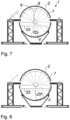
- the tool 7 is displayed in a front view in Figs. 5-10 in several configurations. More specifically, the tool 7 has a fan-type shape and is foldable in a manner similiar to a round hand-held fan.
- the tool 7 may, for example, comprise a hub 8 and spokes 9, schematically illustrated and labelled in Fig. 5 , wherein the spokes 9 are pivotable around the hub 8 for folding and unfolding of the tool 7.
- the spokes 9 of the tool 7 are connected to the hub 8 and support a peripherally extending outer effective region 10 of the tool 7 against the hub 8.
- the tool 7 is supported and guided by the lateral rails 19, and for this purpose, the tool 7 is provided with guiding means 20 capable of interacting with the rails 19 for movable support of the tool 7.
- the tool 7 thus can assume an unfolded first configuration 11, shown in Figs. 5 and 6 , in which the tool 7 substantially fills a cross-section of the fuselage sections 2, 3 in the joint region 5.
- the foldable tool 7 then extends within a space that approximately has the shape of a flat, circular disc.
- the tool 7 may fill this space or most of it, or the flat, circular space may define a virtual envelope around the tool 7. Seen in a radial direction, the tool 7 is located entirely within the interior 110 of the fuselage 101 to be formed.
- the tool 7 can be operated to act on the joint region 5 along an entire circumference of the fuselage 101. More specifically, active elements in the effective region 10 can be actuated to act on the joint region 5.
- active elements in the effective region 10 can be actuated to act on the joint region 5.
- the way of action is explained in the following with further reference to Figs. 11-17 .
- the interior 110 of the fuselage 101 to be formed, and an outer surface 111 of the fuselage 101, are indicated in Figs. 11-17 , too.
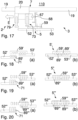
- FIG. 11 A first step of a method for joining the adjacent first and second barrel-shaped fuselage sections 2, 3 of the aircraft fuselage 101 in the circumferential joint region 5 using the arrangement 1 is illustrated in Fig. 11 .
- the tool 7 is axially inserted into the male end portion of the second fuselage section 3 by moving the tool 7 along the rail 19 parallel to the longitudinal direction X, as indicated in Fig. 11 by arrow A1.
- the second fuselage section 3 is supported by a supporting arrangement 31 as described above.
- the tool 7 comprises axially extending engagement elements 47, in particular each shaped as a pin, which fits into a passage of an assigned bush 68 provided on the frame 67, e.g. inserted in an opening thereof.
- each engagement element 47 is axially inserted into the respective bush 68.
- the tool 7 comprises a plurality of male-side active elements 73 and of female-side active elements 79, one element 73 and one element 79 being shown in the detail views of Figs. 11-17 .
- the elements 73, 79 are successively peripherally distributed, preferably in a uniform manner, along the entire circumference of the tool 7 in its unfolded configuration.
- the engagement elements 47 may be peripherally distributed as well along that entire circumference of the tool 7.
- each spoke 9 may be assigned to and/or adapted to carry one or more of the active elements 73, one or more of the active elements 79, and one or more of the engagement elements 47.
- Fig. 12 shows a step subsequent to the step of Fig. 11 , in which the active element 73 is extended, substantially radially in the direction of an arrow A2 in Fig. 11 , so as to abut onto an inner side of the butt-strap 59.
- the tool 7 is fixed in relation to the rails 19 and the frames 67 of the second fuselage section 3.
- the end portion of the second fuselage section 3 has been equipped with the tool 7.
- the first fuselage section 2 is provided and supported by a further supporting arrangement 31.
- the supporting arrangement 31 and the first fuselage section 2 supported by it are axially moved towards the second fuselage section 3 for joining the fuselage sections 2 and 3 in the joint region 5, such that the female-side active element 79 is located on an inner side of the outer skin 52 in the female end portion of the first section 2.
- Fig. 13 shows that in this step, the outer skin 52 of the first fuselage section 2 cannot yet be easily mated with the protruding butt-strap 59 of the male end portion of the second fuselage section 3, and the sections 2 and 3 are still spaced from each other by a small distance. This may in the embodiment displayed in Figs. 11-17 be due to both tolerances and to a configuration and dimensioning that is intended to provide for a form-fit and, if desired, an additional interference fit between the outer skin 52 and butt-strap 59.
- the outer skin 52 comprises a form-fit contour 82 corresponding to a form-fit contour 83 on an outer side of the butt-strap 59.
- the contours 82, 83 are adapted to fittingly engage with each other in order to establish the positive connection of the butt-strap 59 and the outer skin 52.
- the tool 7 is operated to act, from the interior 110 of the fuselage 101 to be formed, onto a material portion 71 that is a part of the outer skin 52 near the female end portion of the first fuselage section 2.
- the female-side active elements 79 are operated to extend, substantially in a radial direction along arrow A3 in Fig. 14 , and apply an outward mechanical force, along the entire circumference of the material portion 71 and preferably in a substantially uniform manner at uniformly spaced locations, on the material portion 71.
- a substantially homogeneous, reversible and elastic expansion of the material portion 71 is caused and the inner dimension thereof is correspondingly increased.
- the active elements 73 and/or 79 in particular the female-side active elements 79, can be actuated in hydraulic or electromechanical manner, for instance.
- the first and second fuselage sections 2 and 3 can be joined in a substantially forceless manner by axially moving the sections 2, 3 and the respective arrangements 31 relative to each other along the longitudinal direction X, e.g. by moving the first fuselage section 2 towards the second fuselage section 3, see Fig. 15 .
- the rails 19 of the rail devices 17 assigned to both the first and second fuselage sections 2 and 3 are connected, in such a manner that the tool 7 can be displaceably guided along both connected rails 17 across the connection.
- the tool 7 is operated so as to retract the female-side active element 79, which allows the elastic expansion of the material portion 71 to be reversed.
- the positive, form-fit connection enabled by the corresponding contours 82, 83 is formed in the joint region 5. Further, an elastic force acting radially may remain, creating an additional interference fit.
- FIG. 6 An expanded state of the foldable tool 7, corresponding to the situation depicted in Figs. 14 and 15 , is illustrated in a front view in Fig. 6 , while a relaxed state of the foldable tool 7, corresponding to the situation e.g. in Figs 13 or 16 , is schematically shown in Fig. 5 .
- the form-fit connection in the joint region 5 can be substantially rivetless.
- the form-fit connection in the joint region 5 may be complemented by riveting.
- blind riveting may be performed along the joint region 5.
- the male-side active element 73 can act as a counter support.
- the joint region 5 therefore can be riveted in an automated, rapid and expedient manner.
- the male-side active element 73 may also serve as a counter support for drilling, e.g. to drill rivet holes.
- a further step illustrated in Fig. 17 , after retracting the male-side active element 73 from the inner side of the butt-strap 59 and retracting the engagement elements 47 from the bushes 68, e.g. by a small axial movement of the tool 7 or by individually actuating the elements 47, the foldable tool 7 is brought into a second configuration 13. This is done by folding the tool 7.
- Folding the tool 7 includes pivoting a number or all of the spokes 9 about the hub 8 in a fan-like manner, see Figs. 7-10 , which illustrate such a folding movement F.
- a pivoting movement may be applied only to some of the spokes 9, or all or most of the spokes 9 may pivot through an angle, e.g. a small angle.
- each of the sections 2 and 3 has already been completed to a considerable extent.
- a passenger floor 23 including a floor frame and most of the floor plates to be supported by the floor frame has already been installed, e.g. as a floor module.
- the tool 7 fills a smaller part of a cross-sectional area of the fuselage 101 than in the first configuration.
- the tool 7 is entirely located above the floor 23, including all of its spokes 9 and the hub 8.
- the tool 7 can be easily removed from the interior 110 by axially displacing the tool 7 along the rails 19 within a space 29 above an upper side 24 of the floor 23, wherein that space 29 is intended to accommodate a passenger cabin in the completed aircraft 100.
- the tool 7 is removed so as to enable and/or facilitate subsequent work in the interior 110.
- the corresponding contours 82 and 83 of the outer skin 52 of the first fuselage section 2 and of the butt-strap 59 are shaped in a smooth, wavy manner, seen in a longitudinal section as in Figs. 11-17 , and are formed integrally with the outer skin 52 and the butt-strap 59, respectively.
- Such contours 82, 83 may be designed to have relatively low requirements with respect to shape and position.
- the contours 82, 83 may be pre-shaped and may then be re-worked before joining the sections 2, 3. Their wavy shape can contribute to optimization of the joint 5 regarding fatigue.
- the joint region may be configured in a different manner.
- the corresponding contours may be implemented using individual, e.g. pin-type, elements 89' inserted into blind recesses or holes provided in each of the outer skins 52', 53' and the butt-strap 59'.
- This is illustrated in schematic manner in Fig. 18 , at (a) for the still unconnected outer skin 52' and butt-strap 59', and at (b) for a completed joint region 5'.
- Such a type of positive connection in the joint region 5' may be manufactured in a facilitated manner.
- the skin 53' and the butt strap 59' may be riveted.
- the corresponding contours may comprise individual, e.g. pin-type, elements 89" inserted into through-holes provided in each of the outer skin 52", 53" and the butt-strap 59".
- This is illustrated in schematic manner in Fig. 19 , at (a) for still unconnected outer skin 52" and butt-strap 59", and at (b) for a completed joint region 5".
- Such a type of positive connection in the joint region 5" may be manufactured in a facilitated manner, too.
- the through-holes required to insert the elements 89" for connecting skin 52" and butt strap 59" may be created after the joint region 5" has been closed.
- the active element 73 may provide counter support.
- the skin 53" and the butt strap 59" can be riveted.
- the butt-strap 59′′′ is connected to the outer skin 53′′′ of the second fuselage section 3 by riveting before the sections 2, 3 are joined. Then, the sections 2, 3 may be joined as described above. Rivet holes for rivets 89′′′ connecting the outer skin 52′′′ and the butt-strap 59′′′ can be drilled with the active element 73 of the tool 7 acting as a counter support, and afterwards, riveting may be performed.
- the active element 73 can also serve as a counter support if blind riveting is desired to be performed.
- Fig. 20 shows at (a) the still unconnected outer skin 52′′′ and butt-strap 59′′′, with some rivets 89′′′ inserted for illustration, and at (b) a completed riveted joint region 5"'.
- Such a type of connection in the joint region 5′′′ may provide a still higher degree of safety.
- the female-side active element 79 may be configured as a temperature-modifying device, in particular a heating device or a combined heating and cooling device, instead of being configured as a mechanical actuator.
- the active element 79 is in such variants capable of changing the temperature of the material portion 71, in particular increasing that temperature by heating the material portion 71 in order to bring about reversible thermal expansion thereof.
- the expansion obtained preferably is substantially homogeneous along the circumference. This expansion can then, in particular in a step analogous to the step illustrated in Fig. 16 , be reversed by deactivating the heating device and letting the material portion 71 cool down, or in other variants by actively cooling the material portion 71. Upon cooling, the material portion 71 then thermally contracts.
- the embodiments of the invention described hereinabove thus provide an advantageous, forceless fuselage connection using a foldable expanding jig, precisely guided and supported in a rail-based manner.
- the process of connecting the sections may be automated.
- the handling of tolerances can be significantly improved.
- automated blind riveting during assembly may also be made possible, and a fast and stress-free fuselage assembly using blind rivets may also be achieved.
Landscapes
- Engineering & Computer Science (AREA)
- Manufacturing & Machinery (AREA)
- Aviation & Aerospace Engineering (AREA)
- Transportation (AREA)
- Mechanical Engineering (AREA)
- Automatic Assembly (AREA)
Abstract
Description
- The invention relates to joining adjacent barrel-shaped fuselage sections of an aircraft fuselage in a circumferentially extending joint region and in particular to an arrangement and method for accomplishing such joining, as well as to a tool for use in joining adjacent barrel-shaped fuselage sections of an aircraft fuselage.
- It is known as such to assemble a fuselage of an aircraft, such as e.g. a passenger or freight aircraft, by joining several barrel-shaped fuselage sections along circumferential joints. However, the fuselage sections are large components, usually having diameters in the order of several meters, and also are lightweight structures that are often slightly elastically deformable under the effect of their own weight.
- Such fuselage sections therefore, despite large efforts for accurate manufacturing thereof, exhibit considerable tolerances, with respect to size and/or shape, that may add up during fuselage assembly and make assembly of adjacent fuselage sections time-consuming and laborious. For example, the sections may not be as round as expected. Therefore, during assembly of the fuselage sections, one may proceed by aligning the floors, e.g. passenger floors, of both sections and compensate the tolerances via a skin butt-strap interface. Additional forces at that interface during assembly may arise from the application of liquid sealant. Also, this kind of connection requires the installation of a large number of fasteners such as rivets. Furthermore, any gaps that may remain, due to the existence of the tolerances mentioned, must be filled to avoid additional fuel consumption. Moreover, assembling the fuselage in this manner may result in considerable work for precisely adjusting cabin components in a laborious and therefore expensive process.
- A method for manufacturing an aircraft fuselage from a multiplicity of fuselage barrels is described in
EP 4 129 817 A1 . The method comprises changing a size of a structural profile, which may be a barrel section, at least at a mating contour by expansion or contraction, e.g. thermally or mechanically. - In view of this background, a problem to be solved by the present invention therefore is to provide an improved arrangement which enables a time-saving, cost-effective and precise assembly of fuselage sections of an aircraft fuselage to each other, as well as to propose a correspondingly improved method and tool.
- This problem is solved by an arrangement having the features of
claim 1 and/or by a tool having the features of claim 12 and/or by a method having the features ofclaim 13. - Accordingly, an arrangement for joining adjacent first and second barrel-shaped fuselage sections of an aircraft fuselage in a circumferentially extending joint region is proposed, wherein the arrangement comprises a foldable tool configured to assume at least an unfolded first configuration and a folded second configuration, and a rail device adapted to support and displaceably guide the tool such that the tool can be moved substantially along a longitudinal direction of the fuselage. In the first configuration, the tool is adapted to be operated to act on the joint region along a circumference of the fuselage from an interior of the fuselage so as to thereby bring about a reversible expansion of a material portion configured to form part of the joint region. Furthermore, in the second configuration, the tool fills a smaller part of a cross-sectional area of the fuselage than in the first configuration.
- Furthermore, in accordance with the invention, a foldable tool for use in joining adjacent first and second barrel-shaped fuselage sections of an aircraft fuselage in a circumferentially extending joint region is provided. The tool is configured to assume at least an unfolded first configuration and a folded second configuration, and is adapted to be supported and displaceably guided such that the tool can be moved substantially along a longitudinal direction of the fuselage. In the first configuration, the tool is adapted to be operated to act on the joint region along a circumference of the fuselage from an interior of the fuselage so as to thereby bring about an expansion of a material portion configured to form part of the joint region. In the second configuration, the tool fills a smaller part of a cross-sectional area of the fuselage than in the first configuration.
- Still further, the invention proposes a method for joining adjacent first and second barrel-shaped fuselage sections of an aircraft fuselage in a circumferential joint region. In particular, the method may be performed using the arrangement and/or the tool provided in accordance with the invention.
- The method comprises steps of:
- providing a foldable tool configured to assume at least an unfolded first configuration and a folded second configuration, and a rail device adapted to support and displaceably guide the tool such that the tool can be moved substantially along a longitudinal direction of the fuselage;
- in a state in which the first and second fuselage sections are spaced apart from each other by a distance along the longitudinal direction, operating the tool, which assumes the first configuration, to act on the joint region along a circumference of the fuselage from an interior of the fuselage and thereby bringing about a reversible expansion of a material portion configured to form part of the joint region;
- relatively moving the first and second fuselage sections towards each other along the longitudinal direction so as to close the joint region;
- operating the tool so as to reverse the expansion of the material portion;
- bringing the tool into the second configuration in which the tool fills a smaller part of a cross-sectional area of the fuselage than in the first configuration; and
- moving the tool on the rail device substantially along the longitudinal direction in order to axially remove the tool from the interior of the fuselage.
- It is an idea of the invention to use a tool, configured in the manner of a foldable jig and capable of inducing a reversible expansion, to ensure a substantially forceless connection of adjacent barrel-type fuselage sections. By expanding the material portion that is part of the joint, the adjacent fuselage sections can be easily mated and forces due to tolerances of the individual sections and corresponding geometrical and/or dimensional mismatch at the circumferential joint, which usually would act in a non-uniform manner, are largely prevented from arising. The possibility provided by the invention to actively deform a fuselage section, at least within an end portion thereof in and near the joint region, using the expansion tool makes it possible to mitigate tolerance-driven deformations and obtain a zero-zero position to the masterline. In particular, a surface-driven masterline is made possible. For example, the foldable tool can also act as a deformation tool in order to modify and correct the shape of the fuselage section. The invention thus enables substantially zero tolerance and zero deformation fuselage installation.
- Hence, the invention enables a rapid assembly of the fuselage sections to each other, as well as further improved quality and geometrical accuracy of the fuselage and the cabin installed therein. Much laborious adjustment work, e.g. on cabin components, may be dispensed with.
- Furthermore, before joining the fuselage sections, these sections can be completed to a large extent, including most of the floor, in particular of the passenger floor. The foldable tool, capable of acting on the joint region along the circumference of the fuselage from the interior thereof when the tool is unfolded, can be folded to assume the second configuration in which its size is considerably reduced. Thus, even though the floor is installed in both the first and second sections, the foldable tool can be easily removed after the circumferential joint has been formed.
- Advantageous improvements and developments of the invention are contained in the dependent claims as well as in the description referring to the drawings.
- In a development, the tool may be operable to act on the material portion at successive locations along the circumference of the fuselage in the joint region, or may be operable to act on the material portion in a substantially continuous manner along the circumference. For instance, it may be expedient to mechanically act on the material portion, to obtain the expansion, at a plurality of locations, while in other implementations it may be expedient to apply for example heat in a continuous manner along the circumference.
- In a preferred development, the tool is configured in a fan-type manner. In particular, the tool can be folded in the manner of a hand fan. In this manner, the first and second configurations can be well adapted to a generally round cross-sectional shape of a fuselage. For example, by providing the tool with a fan-type foldability, the tool can be easily confined in the second configuration to a space that is not much larger than approximately half of the cross-section of the fuselage in the joint region, while in the first configuration, the foldable tool may for instance fill this cross-section substantially completely. Thus, a single tool can be used to act on the complete circumference and can easily be removed as a single unit.
- In a development, in the first configuration, the tool is capable of acting on the joint region along substantially the entire circumference of the fuselage. Thereby, advantageously, the complete joint region can be prepared for mating the fuselage sections along the entire circumference.
- In particular, the material portion which can be expanded by action of the tool is part of an end portion of the first fuselage section and the tool is further adapted to be operated to abut on and/or mechanically engage with an end portion of the second fuselage section. This enables a precise positioning of the tool relative to the second fuselage section, in particular before bringing about the expansion of the material portion.
- In a development, the end portion of the first fuselage section forms a female part of the joint region and the material portion which can be expanded by action of the tool is a portion of an outer skin of the first fuselage section. In this development, furthermore, the end portion of the second fuselage section forms a male part of the joint region and the tool is further adapted to be operated to mechanically abut on a butt strap of the second fuselage section and/or to engage with a frame of the second fuselage section adjacent the joint region.
- According to an improvement, in the first configuration the tool extends, in a cross-section of the fuselage in the joint region, within a space having approximately the shape of a flat, circular disc. In this manner, the tool can be used to implement the circumferential joint when floor sections or modules are already installed, for the most part, in the fuselage sections, leaving only a narrow space around the joint in which floor plates, for example, still have to be installed after the fuselage sections have been joined.
- According to a development, in the second configuration the tool extends entirely within a space on a single side of a floor formed by floor sections or modules installed in the first and second fuselage sections, in particular of a passenger floor, and preferably extends entirely within a space on an upper side of that floor. In this way, the foldable tool can easily be removed from the interior of the fuselage after having fulfilled its function, by axially displacing the tool, in particular using the rail device. Further, the space above the floor is usually sufficiently large for this purpose, in particular larger than the upper half of a circular disc, as this upper space in passenger airplanes accommodates the passenger cabin.
- In a development, the tool may be adapted to bring about the expansion of the material portion configured to form part of the joint region by applying mechanical force onto the material portion, in particular in hydraulic or electromechanical manner. This can help to generate a precisely defined expansion and also a correction of the shape of the material portion and the end portion of the fuselage section to which it is connected.
- Further, in another development, the tool may be adapted to bring about the expansion of the material portion configured to form part of the joint region by introducing heat into the material portion. For example, in this way a uniform, reversible expansion can be brought about in a simple manner and may be accomplished with no or only gentle surface contact, which in turn may contribute to protecting the surfaces of the fuselage section(s) and/or may enable a comparatively simple geometry of the tool.
- In a development, the tool is adapted to additionally provide a counter support for blind riveting in the circumferential joint region, in particular using a riveting machine. Thereby, it becomes possible to perform blind riveting in the joint region, without load introduction or possible deformation.
- According to a further development, the rail device comprises rails each extending substantially along a direction parallel to the longitudinal direction of the fuselage through an interior of each of the barrel-shaped fuselage sections, preferably laterally on both sides of the fuselage within the interior of the fuselage sections. This makes it possible to effectively support the tool in a displaceable manner and enables rail-guided axial extraction of the tool from the fuselage.
- According to a still further development, the rail device is supported by a supporting arrangement provided outside of the barrel-shaped fuselage sections and by cantilever arms each extending from the supporting arrangement through an opening in a skin of the fuselage section to the rail device. The rail device thus can be supported without obstructing open ends of the fuselage sections, where these are to be joined to adjacent ones.
- In a development of the method, the material portion which is expanded by action of the tool is part of an end portion of the first fuselage section, in particular a portion of an outer skin of the first fuselage section. In this development, before the expansion of the material portion is brought about, the tool is brought into abutment and/or mechanical engagement with an end portion of the second fuselage section, in particular is operated to abut on a butt strap of the second fuselage section and/or to engage with a frame of the second fuselage section adjacent the joint region.
- In a development of the method, joining the first and second fuselage sections includes creating a positive connection by reversing the expansion of the material portion and/or includes riveting after reversing the expansion of the material portion. A positive or form-fit connection may enable a rapid, time-saving process for joining the fuselage sections, and may help to dispense with at least part of the total number of rivets in the joint region, or may even enable a substantially rivetless assembly. The reversible expansion using the foldable tool and/or the arrangement makes it possible to obtain such a form-fit connection in an efficient manner.
- The developments, improvements and implementations of the invention described above can be applied in analogous manner to each of the arrangement, folding tool and method of the invention.
- The present invention is explained in more detail below with reference to the embodiments shown in the schematic figures, wherein:
- Fig. 1
- shows an exemplary aircraft and illustrates fuselage sections as well as joints between these in schematic manner;
- Fig. 2
- schematically illustrates the joining of adjacent first and second barrel-shaped fuselage sections by connecting a female end portion of the first fuselage section and a male portion of the second fuselage section, and shows in subfigure (a) a schematic overview of the joining process as well as in subfigure (b) a detail sectional view in a joint region that is to be formed;
- Figs. 3-10
- illustrate an arrangement for joining two fuselage sections in accordance with an embodiment of the invention in end views and show a way of operating the arrangement in accordance with the embodiment by illustration of various method steps;
- Figs. 11-17
- illustrate, in detail sectional views, a plurality of successive steps of a process of joining the first and second fuselage sections using the arrangement according to the embodiment; and
- Figs. 18-20
- illustrate detail sectional views of a butt-strap skin interface in the circumferentialjoint region according to further, alternative embodiments.
- In the figures of the drawing, elements, features and components which are identical, functionally identical and of identical action are denoted in each case by the same reference designations unless stated otherwise.
-
Fig. 1 shows anexemplary aircraft 100 comprising afuselage 101 with anose 102, anempennage 103,wings 104 andengines 105 attached to thewings 104. Thefuselage 101 is formed by assembling a plurality of barrel-shaped fuselage sections, of whichexemplary fuselage sections Fig. 1 . Adjacent fuselage sections are connected to each other in circumferentialjoint regions 5a-5d. - A
first fuselage section 2 and asecond fuselage section 3 are schematically shown inFig. 2 during joining a male end portion of thesecond fuselage section 3 with a female end portion of thefirst fuselage section 2 in a circumferentialjoint region 5.Fig. 2 shows in the sectional detail view at (b) that the female end portion of thefirst fuselage section 2 is formed with anouter skin 52 having an inner dimension D2, e.g. a diameter. Further,Fig. 2 shows that the male end portion of thesecond fuselage section 3 is formed with anouter skin 53, abutt strap 59 attached on an inner side of theouter skin 53 so as to axially protrude beyond an end edge of theouter skin 53 towards thefirst fuselage section 2, and with acircumferentially extending frame 67, attached to an inner side of theouter skin 53 using aclip 61, via thebutt strap 59 which is interposed between theclip 61 and theskin 53. Thebutt strap 59 defines an outer dimension d3, e.g. a diameter, of the male end portion. - The shape of these end regions as well as the dimensions d3, D2 are subject to tolerances. In some cases, D2 may be smaller than d3, and the
sections - An
arrangement 1 for joining the adjacent first and second barrel-shapedfuselage sections joint region 5, which may for instance be any of thejoint regions 5a-5d ofFig. 1 , and its mode of operation, are described in the following in accordance with an embodiment of the invention with reference toFigs. 5-17 . - The
arrangement 1 comprises a supportingarrangement 31 for each of thefuselage sections arrangement 31 for thefirst fuselage section 2 is shown inFigs. 3-10 in exemplary manner. An analogous supporting arrangement is provided for thesecond fuselage section 3. The supportingarrangement 31 is located outside of thefuselage section - The supporting
arrangement 31 comprises alower support 35 adapted to receive a lower region of thefuselage section outer skin fuselage section support devices 37 are arranged. Thesupport devices 37 may each be movable at least in a lateral direction, transverse to a longitudinal axis of thefuselage section 2. Eachsupport device 37 carries acantilever arm 41 which can be moved horizontally as well as vertically on thesupport device 37 in a controllable manner. In the situation inFigs. 3-10 , each of thecantilever arms 41 extends through anopening 43 in thefuselage section outer skin fuselage 101 that is to be formed. - The
arrangement 1 further comprises arail device 17 which is supported by the supportingarrangement 31. More specifically, therail device 17 includesrails 19 each carried by thecantilever arms 41. Eachrail 19 extends longitudinally through an interior of thefuselage section 2, and thus through theinterior 110 of thefuselage 101 to be assembled, laterally on both sides of thefuselage section 2. Accordingly, therails 19 extend substantially parallel to a longitudinal direction X or flight direction of thefuselage 101. - On the
rails 19, afoldable tool 7 is displaceably supported and guided. Thetool 7 is thereby movable in a direction parallel to the longitudinal direction X of thefuselage 101. Thetool 7 is displayed in a front view inFigs. 5-10 in several configurations. More specifically, thetool 7 has a fan-type shape and is foldable in a manner similiar to a round hand-held fan. Thetool 7 may, for example, comprise ahub 8 andspokes 9, schematically illustrated and labelled inFig. 5 , wherein thespokes 9 are pivotable around thehub 8 for folding and unfolding of thetool 7. Thespokes 9 of thetool 7 are connected to thehub 8 and support a peripherally extending outereffective region 10 of thetool 7 against thehub 8. It is to be noted thattool 7 is supported and guided by the lateral rails 19, and for this purpose, thetool 7 is provided with guiding means 20 capable of interacting with therails 19 for movable support of thetool 7. - The
tool 7 thus can assume an unfoldedfirst configuration 11, shown inFigs. 5 and 6 , in which thetool 7 substantially fills a cross-section of thefuselage sections joint region 5. In thefirst configuration 11, thefoldable tool 7 then extends within a space that approximately has the shape of a flat, circular disc. Thetool 7 may fill this space or most of it, or the flat, circular space may define a virtual envelope around thetool 7. Seen in a radial direction, thetool 7 is located entirely within theinterior 110 of thefuselage 101 to be formed. - In the
first configuration 11, thetool 7 can be operated to act on thejoint region 5 along an entire circumference of thefuselage 101. More specifically, active elements in theeffective region 10 can be actuated to act on thejoint region 5. The way of action is explained in the following with further reference toFigs. 11-17 . For the sake of clarity, theinterior 110 of thefuselage 101 to be formed, and anouter surface 111 of thefuselage 101, are indicated inFigs. 11-17 , too. - A first step of a method for joining the adjacent first and second barrel-shaped
fuselage sections aircraft fuselage 101 in the circumferentialjoint region 5 using thearrangement 1 is illustrated inFig. 11 . Thetool 7 is axially inserted into the male end portion of thesecond fuselage section 3 by moving thetool 7 along therail 19 parallel to the longitudinal direction X, as indicated inFig. 11 by arrow A1. Thesecond fuselage section 3 is supported by a supportingarrangement 31 as described above. Thetool 7 comprises axially extendingengagement elements 47, in particular each shaped as a pin, which fits into a passage of an assignedbush 68 provided on theframe 67, e.g. inserted in an opening thereof. As thetool 7 is axially moved into the male end portion of thesecond fuselage section 3, eachengagement element 47 is axially inserted into therespective bush 68. - In the
effective region 10, thetool 7 comprises a plurality of male-sideactive elements 73 and of female-sideactive elements 79, oneelement 73 and oneelement 79 being shown in the detail views ofFigs. 11-17 . Theelements tool 7 in its unfolded configuration. Further, for instance, theengagement elements 47 may be peripherally distributed as well along that entire circumference of thetool 7. For example, each spoke 9 may be assigned to and/or adapted to carry one or more of theactive elements 73, one or more of theactive elements 79, and one or more of theengagement elements 47. -
Fig. 12 shows a step subsequent to the step ofFig. 11 , in which theactive element 73 is extended, substantially radially in the direction of an arrow A2 inFig. 11 , so as to abut onto an inner side of the butt-strap 59. In this way, thetool 7 is fixed in relation to therails 19 and theframes 67 of thesecond fuselage section 3. At the end of the step ofFig. 12 , the end portion of thesecond fuselage section 3 has been equipped with thetool 7. - Axially adjacent to and coaxial with the
second fuselage section 3, and spaced therefrom by an axial distance, thefirst fuselage section 2 is provided and supported by a further supportingarrangement 31. The supportingarrangement 31 and thefirst fuselage section 2 supported by it are axially moved towards thesecond fuselage section 3 for joining thefuselage sections joint region 5, such that the female-sideactive element 79 is located on an inner side of theouter skin 52 in the female end portion of thefirst section 2.Fig. 13 shows that in this step, theouter skin 52 of thefirst fuselage section 2 cannot yet be easily mated with the protruding butt-strap 59 of the male end portion of thesecond fuselage section 3, and thesections Figs. 11-17 be due to both tolerances and to a configuration and dimensioning that is intended to provide for a form-fit and, if desired, an additional interference fit between theouter skin 52 and butt-strap 59. - On the inner side, the
outer skin 52 comprises a form-fit contour 82 corresponding to a form-fit contour 83 on an outer side of the butt-strap 59. Thecontours strap 59 and theouter skin 52. - In order to be able to close the joint 5 and connect the
outer skin 52 and the butt-strap 59, thetool 7 is operated to act, from theinterior 110 of thefuselage 101 to be formed, onto amaterial portion 71 that is a part of theouter skin 52 near the female end portion of thefirst fuselage section 2. For this purpose, the female-sideactive elements 79 are operated to extend, substantially in a radial direction along arrow A3 inFig. 14 , and apply an outward mechanical force, along the entire circumference of thematerial portion 71 and preferably in a substantially uniform manner at uniformly spaced locations, on thematerial portion 71. Thereby, a substantially homogeneous, reversible and elastic expansion of thematerial portion 71 is caused and the inner dimension thereof is correspondingly increased. - The
active elements 73 and/or 79, in particular the female-sideactive elements 79, can be actuated in hydraulic or electromechanical manner, for instance. - After the
material portion 71 has been expanded, the first andsecond fuselage sections sections respective arrangements 31 relative to each other along the longitudinal direction X, e.g. by moving thefirst fuselage section 2 towards thesecond fuselage section 3, seeFig. 15 . In this step, therails 19 of therail devices 17 assigned to both the first andsecond fuselage sections tool 7 can be displaceably guided along both connectedrails 17 across the connection. - In a subsequent step, illustrated in
Fig. 16 , thetool 7 is operated so as to retract the female-sideactive element 79, which allows the elastic expansion of thematerial portion 71 to be reversed. In this way, the positive, form-fit connection enabled by the correspondingcontours joint region 5. Further, an elastic force acting radially may remain, creating an additional interference fit. - An expanded state of the
foldable tool 7, corresponding to the situation depicted inFigs. 14 and 15 , is illustrated in a front view inFig. 6 , while a relaxed state of thefoldable tool 7, corresponding to the situation e.g. inFigs 13 or16 , is schematically shown inFig. 5 . - In some variants, the form-fit connection in the
joint region 5 can be substantially rivetless. In other implementations, the form-fit connection in thejoint region 5 may be complemented by riveting. In particular, blind riveting may be performed along thejoint region 5. When performing the blind riveting, schematically indicated by arrow A4 inFig. 16 , the male-sideactive element 73 can act as a counter support. Thejoint region 5 therefore can be riveted in an automated, rapid and expedient manner. The male-sideactive element 73 may also serve as a counter support for drilling, e.g. to drill rivet holes. - In a further step, illustrated in
Fig. 17 , after retracting the male-sideactive element 73 from the inner side of the butt-strap 59 and retracting theengagement elements 47 from thebushes 68, e.g. by a small axial movement of thetool 7 or by individually actuating theelements 47, thefoldable tool 7 is brought into asecond configuration 13. This is done by folding thetool 7. Folding thetool 7 includes pivoting a number or all of thespokes 9 about thehub 8 in a fan-like manner, seeFigs. 7-10 , which illustrate such a folding movement F. Thus, a pivoting movement may be applied only to some of thespokes 9, or all or most of thespokes 9 may pivot through an angle, e.g. a small angle. - Before both
sections joint region 5, each of thesections sections passenger floor 23 including a floor frame and most of the floor plates to be supported by the floor frame has already been installed, e.g. as a floor module. After folding thetool 7 to assume thesecond configuration 13, thetool 7 fills a smaller part of a cross-sectional area of thefuselage 101 than in the first configuration. Specifically, in the embodiment illustrated in the Figures, in thesecond configuration 13 thetool 7 is entirely located above thefloor 23, including all of itsspokes 9 and thehub 8. - Therefore, after assuming the
second configuration 13, thetool 7 can be easily removed from the interior 110 by axially displacing thetool 7 along therails 19 within aspace 29 above anupper side 24 of thefloor 23, wherein thatspace 29 is intended to accommodate a passenger cabin in the completedaircraft 100. By moving thetool 7 in this step along an extraction direction E, parallel to the longitudinal direction X, thetool 7 is removed so as to enable and/or facilitate subsequent work in theinterior 110. - In the embodiment explained herein above with reference in particular to
Figs. 11-17 , the correspondingcontours outer skin 52 of thefirst fuselage section 2 and of the butt-strap 59 are shaped in a smooth, wavy manner, seen in a longitudinal section as inFigs. 11-17 , and are formed integrally with theouter skin 52 and the butt-strap 59, respectively.Such contours contours sections - However, in other embodiments, the joint region may be configured in a different manner.
- For example, in a second embodiment, the corresponding contours may be implemented using individual, e.g. pin-type, elements 89' inserted into blind recesses or holes provided in each of the outer skins 52', 53' and the butt-strap 59'. This is illustrated in schematic manner in
Fig. 18 , at (a) for the still unconnected outer skin 52' and butt-strap 59', and at (b) for a completed joint region 5'. Such a type of positive connection in the joint region 5' may be manufactured in a facilitated manner. In a variant, the skin 53' and the butt strap 59' may be riveted. - Further, in a third exemplary embodiment, the corresponding contours may comprise individual, e.g. pin-type,
elements 89" inserted into through-holes provided in each of theouter skin 52", 53" and the butt-strap 59". This is illustrated in schematic manner inFig. 19 , at (a) for still unconnectedouter skin 52" and butt-strap 59", and at (b) for a completedjoint region 5". Such a type of positive connection in thejoint region 5" may be manufactured in a facilitated manner, too. In the embodiment ofFig. 19 , the through-holes required to insert theelements 89" for connectingskin 52" andbutt strap 59" may be created after thejoint region 5" has been closed. For such a drilling step, theactive element 73 may provide counter support. In a variant, theskin 53" and thebutt strap 59" can be riveted. - Still further, in a fourth exemplary embodiment, the butt-
strap 59‴ is connected to theouter skin 53‴ of thesecond fuselage section 3 by riveting before thesections sections rivets 89‴ connecting theouter skin 52‴ and the butt-strap 59‴ can be drilled with theactive element 73 of thetool 7 acting as a counter support, and afterwards, riveting may be performed. Theactive element 73 can also serve as a counter support if blind riveting is desired to be performed. -
Fig. 20 shows at (a) the still unconnectedouter skin 52‴ and butt-strap 59‴, with somerivets 89‴ inserted for illustration, and at (b) a completed rivetedjoint region 5"'. Such a type of connection in thejoint region 5‴ may provide a still higher degree of safety. - In further variants of each of the embodiments described above, the female-side
active element 79 may be configured as a temperature-modifying device, in particular a heating device or a combined heating and cooling device, instead of being configured as a mechanical actuator. Theactive element 79 is in such variants capable of changing the temperature of thematerial portion 71, in particular increasing that temperature by heating thematerial portion 71 in order to bring about reversible thermal expansion thereof. The expansion obtained preferably is substantially homogeneous along the circumference. This expansion can then, in particular in a step analogous to the step illustrated inFig. 16 , be reversed by deactivating the heating device and letting thematerial portion 71 cool down, or in other variants by actively cooling thematerial portion 71. Upon cooling, thematerial portion 71 then thermally contracts. - The embodiments of the invention described hereinabove thus provide an advantageous, forceless fuselage connection using a foldable expanding jig, precisely guided and supported in a rail-based manner. The process of connecting the sections may be automated. Advantageously, the handling of tolerances can be significantly improved. Moreover, automated blind riveting during assembly may also be made possible, and a fast and stress-free fuselage assembly using blind rivets may also be achieved.
- The embodiments of the invention described herein thus provide some or more advantages of:
- further improved quality and precision of the assembled fuselage;
- considerable speed increase of the assembly of the fuselage barrels;
- using specially shaped form-fit contours at the circumferential joint, considerable improvements of fatigue and structural performance;
- in some implementations, improvement of corrosion resistance due to the possibility of using advanced materials, avoiding constraints of conventional fastening techniques;
- a possibility of integrating an elastomer seal element at the section joint as a new way of sealing, instead of using a liquid sealant that requires time for curing;
- a possibility to actively deform the fuselage section using the expansion tool to mitigate tolerance driven deformations, provide a zero-zero position to the masterline and enable a surface-driven masterline;
- a possibility of shape-forming the fuselage section using the tool;
- facilitating a precise installation of further components in the fuselage later, in particular cabin components, and reducing complex and laborious adjustment of these;
- enabling a crossbeam free fuselage connection and installation of the floor grid as a substantially complete module in each fuselage section;
- simple removal of the foldable tool due to the round-folding-fan principle, in particular by rail-guided extraction from the fuselage;
- a possibility to perform expedient and rapid blind-riveting;
- a reduction of the stay-out zone in the joint region connecting the fuselage sections;
- providing a rail-based assembly interface to the frame, thereby allowing a controlled, steered fuselage section assembly.
- Even though the invention has been completely described above with reference to embodiments of the invention, the invention is not limited to these embodiments but may be modified in many ways.
-
- 1
- arrangement
- 2
- first fuselage section
- 3
- second fuselage section
- 5, 5', 5", 5‴
- joint region
- 5a-d
- joint region
- 7
- tool
- 8
- hub
- 9
- spoke
- 10
- effective region
- 11
- unfolded configuration
- 13
- folded configuration
- 17
- rail device
- 19
- rail
- 20
- guiding means
- 23
- floor
- 24
- upper side (floor)
- 29
- interior space for accommodating passenger cabin
- 31
- supporting arrangement
- 35
- lower support
- 37
- support device
- 41
- cantilever arm
- 43
- opening
- 47
- engagement element (tool)
- 52
- outer skin (first fuselage section)
- 53
- outer skin (second fuselage section)
- 59
- butt strap
- 61
- clip
- 67
- frame
- 68
- bush
- 71
- material portion
- 73
- active element (tool)
- 79
- active element (tool)
- 82
- form-fit contour (first fuselage section)
- 83
- form-fit contour (second fuselage section)
- 89'
- element
- 89"
- element
- 89‴
- rivet
- 100
- aircraft
- 101
- fuselage
- 102
- nose
- 103
- empennage
- 104
- wing
- 105
- engine
- 110
- interior (fuselage)
- 111
- outer surface (fuselage)
- X
- longitudinal direction
- D2
- inner dimension
- d3
- outer dimension
- A1, A2, A3, A4
- arrow
- E
- extraction movement
- F
- folding movement
Claims (15)
- Arrangement (1) for joining adjacent first and second barrel-shaped fuselage sections (2, 3) of an aircraft fuselage (101) in a circumferentially extending joint region (5, 5a-d; 5'; 5"; 5‴), the arrangement (1) comprisinga foldable tool (7) configured to assume at least an unfolded first configuration (11) and a folded second configuration (13), anda rail device (17) adapted to support and displaceably guide the tool (7) such that the tool (7) can be moved substantially along a longitudinal direction (X) of the fuselage;wherein in the first configuration (11), the tool (7) is adapted to be operated to act on the joint region (5, 5a-d; 5'; 5"; 5‴) along a circumference of the fuselage (101) from an interior (110) of the fuselage (101) so as to thereby bring about a reversible expansion of a material portion (71) configured to form part of the joint region (5, 5a-d; 5'; 5"; 5‴), andwherein in the second configuration (13), the tool fills a smaller part of a cross-sectional area of the fuselage (101) than in the first configuration (11).
- Arrangement according to claim 1,
characterized in that the tool (7) is configured in a fan-type manner and in particular in that the tool (7) can be folded in the manner of a hand fan. - Arrangement according to claim 1 or 2,
characterized in that in the first configuration, the tool (7) is capable of acting on the joint region (5, 5a-d; 5'; 5"; 5‴) along substantially the entire circumference of the fuselage (101). - Arrangement according to any one of the preceding claims,
characterized in that the material portion (71) which can be expanded by action of the tool (7) is part of an end portion of the first fuselage section (2) and that the tool (7) is further adapted to be operated to abut on and/or mechanically engage with an end portion of the second fuselage section (3). - Arrangement according to claim 4,
characterized in that the end portion of the first fuselage section (2) forms a female part of the joint region (5, 5a-d; 5'; 5"; 5‴) and the material portion (71) which can be expanded by action of the tool (7) is a portion of an outer skin (52) of the first fuselage section (2), and in that the end portion of the second fuselage section (3) forms a male part of the joint region (5, 5a-d; 5'; 5"; 5‴) and the tool (7) is further adapted to be operated to mechanically abut on a butt strap (59; 59'; 59"; 59‴) of the second fuselage section (3) and/or to engage with a frame (67) of the second fuselage section (3) adjacent the joint region (5, 5a-d; 5'; 5"; 5‴). - Arrangement according to any one of the preceding claims,
characterized in that in the first configuration (11), the tool (7) extends, in a cross-section of the fuselage (101) in the joint region (5, 5a-d; 5'; 5"; 5‴), within a space having approximately the shape of a flat, circular disc. - Arrangement according to any one of the preceding claims,
characterized in that in the second configuration (13), the tool (7) extends entirely within a space on a single side (24) of a floor (23) formed by floor sections or modules installed in the first and second fuselage sections (2, 3), in particular of a passenger floor, and preferably extends entirely within a space (29) on an upper side (24) of that floor (23). - Arrangement according to any one of the preceding claims,
characterized in that the tool (7) is adapted to bring about the expansion of the material portion (71) configured to form part of the joint region (5, 5a-d; 5'; 5"; 5‴) by applying mechanical force onto the material portion (71), in particular in hydraulic or electromechanical manner. - Arrangement according to any one of the preceding claims,
characterized in that the tool (7) is adapted to bring about the expansion of the material portion (71) configured to form part of the joint region (5, 5a-d; 5'; 5"; 5‴) by introducing heat into the material portion (71). - Arrangement according to any one of the preceding claims,
characterized in that the tool (7) is adapted to additionally provide a counter support for blind riveting in the circumferential joint region (5, 5a-d; 5'; 5"; 5'"). - Arrangement according to any one of the preceding claims,
characterized in that the rail device (17) comprises rails (19) each extending substantially along a direction parallel to the longitudinal direction (X) of the fuselage (101) through an interior of each of the barrel-shaped fuselage sections (2, 3), preferably laterally on both sides of the fuselage (101) within the interior of the fuselage sections (2, 3), and/or in that the rail device (17) is supported by a supporting arrangement (31) provided outside of the barrel-shaped fuselage sections (2, 3) and by cantilever arms (41) each extending from the supporting arrangement (31) through an opening (43) in a skin (52, 53; 52', 53'; 52", 53"; 52‴, 53‴) of the fuselage section (2, 3) to the rail device (17). - Foldable tool (7) for use in joining adjacent first and second barrel-shaped fuselage sections (2, 3) of an aircraft fuselage (101) in a circumferentially extending joint region (5, 5a-d; 5'; 5"; 5‴),wherein the tool (7) is configured to assume at least an unfolded first configuration (11) and a folded second configuration (13), andwherein the tool (7) is adapted to be supported and displaceably guided such that the tool (7) can be moved substantially along a longitudinal direction (X) of the fuselage (101);wherein in the first configuration (11), the tool (7) is adapted to be operated to act on the joint region (5, 5a-d; 5'; 5"; 5‴) along a circumference of the fuselage (101) from an interior (110) of the fuselage (101) so as to thereby bring about an expansion of a material portion (71) configured to form part of the joint region (5, 5a-d; 5'; 5"; 5‴), andwherein in the second configuration (13), the tool (7) fills a smaller part of a cross-sectional area of the fuselage (101) than in the first configuration (11).
- Method for joining adjacent first and second barrel-shaped fuselage sections (2, 3) of an aircraft fuselage (101) in a circumferential joint region (5, 5a-d; 5'; 5"; 5‴), in particular using the arrangement (1) according to any of claims 1 to 11 and/or the tool (7) according to claim 12, comprising steps of:providing a foldable tool (7) configured to assume at least an unfolded first configuration (11) and a folded second configuration (13), and a rail device (17) adapted to support and displaceably guide the tool (7) such that the tool (7) can be moved substantially along a longitudinal direction (X) of the fuselage (101);in a state in which the first and second fuselage sections (2, 3) are spaced apart from each other by a distance along the longitudinal direction (X), operating the tool (7), which assumes the first configuration, to act on the joint region (5, 5a-d; 5'; 5"; 5‴) along a circumference of the fuselage (101) from an interior (110) of the fuselage (101) and thereby bringing about a reversible expansion of a material portion (71) configured to form part of the joint region (5, 5a-d; 5'; 5"; 5‴);relatively moving the first and second fuselage sections (2, 3) towards each other along the longitudinal direction (x) so as to close the joint region (5, 5a-d; 5'; 5"; 5‴);operating the tool (7) so as to reverse the expansion of the material portion (71);bringing the tool (7) into the second configuration (13) in which the tool fills a smaller part of a cross-sectional area of the fuselage (101) than in the first configuration (11); andmoving the tool (7) on the rail device (17) substantially along the longitudinal direction (X) in order to axially remove the tool (7) from the interior (110) of the fuselage (101).
- Method according to claim 13,
characterized in that the material portion (71) which is expanded by action of the tool (7) is part of an end portion of the first fuselage section (2), in particular a portion of an outer skin (52; 52'; 52"; 52‴) of the first fuselage section (2), and that before the expansion of the material portion (71) is brought about, the tool (7) is brought into abutment and/or mechanical engagement with an end portion of the second fuselage section (3), in particular is operated to abut on a butt strap (59) of the second fuselage section (3) and/or to engage with a frame (67) of the second fuselage section (3) adjacent the joint region (5, 5a-d; 5'; 5"; 5‴). - Method according to claim 13 or 14,
characterized in that joining the first and second fuselage sections (2, 3 includes creating a positive connection by reversing the expansion of the material portion (71) and/or includes riveting after reversing the expansion of the material portion (71).
Priority Applications (1)
| Application Number | Priority Date | Filing Date | Title |
|---|---|---|---|
| EP23206762.9A EP4549311B1 (en) | 2023-10-30 | 2023-10-30 | Arrangement and method for joining adjacent barrel-shaped fuselage sections of an aircraft fuselage |
Applications Claiming Priority (1)
| Application Number | Priority Date | Filing Date | Title |
|---|---|---|---|
| EP23206762.9A EP4549311B1 (en) | 2023-10-30 | 2023-10-30 | Arrangement and method for joining adjacent barrel-shaped fuselage sections of an aircraft fuselage |
Publications (2)
| Publication Number | Publication Date |
|---|---|
| EP4549311A1 true EP4549311A1 (en) | 2025-05-07 |
| EP4549311B1 EP4549311B1 (en) | 2026-04-22 |
Family
ID=88600442
Family Applications (1)
| Application Number | Title | Priority Date | Filing Date |
|---|---|---|---|
| EP23206762.9A Active EP4549311B1 (en) | 2023-10-30 | 2023-10-30 | Arrangement and method for joining adjacent barrel-shaped fuselage sections of an aircraft fuselage |
Country Status (1)
| Country | Link |
|---|---|
| EP (1) | EP4549311B1 (en) |
Citations (6)
| Publication number | Priority date | Publication date | Assignee | Title |
|---|---|---|---|---|
| US20130117983A1 (en) * | 2009-12-25 | 2013-05-16 | Kawasaki Jukogyo Kabushiki Kaisha | Assembling method of mandrel used for manufacturing composite material structure and assembling apparatus of mandrel |
| US20140077471A1 (en) * | 2012-09-18 | 2014-03-20 | The Boeing Company | Transport and assembly system and method for composite barrel segments |
| EP3040265A1 (en) * | 2015-01-02 | 2016-07-06 | Airbus Operations GmbH | Method for joining two fuselage sections and mounting device |
| EP4000885A1 (en) * | 2020-11-18 | 2022-05-25 | The Boeing Company | Method for processing a composite structure |
| EP4129817A1 (en) | 2021-08-06 | 2023-02-08 | Airbus Operations GmbH | Method for joining structural profiles |
| WO2023199236A1 (en) * | 2022-04-14 | 2023-10-19 | Leonardo S.P.A. | Equipment and process for making a structural element in composite material |
-
2023
- 2023-10-30 EP EP23206762.9A patent/EP4549311B1/en active Active
Patent Citations (6)
| Publication number | Priority date | Publication date | Assignee | Title |
|---|---|---|---|---|
| US20130117983A1 (en) * | 2009-12-25 | 2013-05-16 | Kawasaki Jukogyo Kabushiki Kaisha | Assembling method of mandrel used for manufacturing composite material structure and assembling apparatus of mandrel |
| US20140077471A1 (en) * | 2012-09-18 | 2014-03-20 | The Boeing Company | Transport and assembly system and method for composite barrel segments |
| EP3040265A1 (en) * | 2015-01-02 | 2016-07-06 | Airbus Operations GmbH | Method for joining two fuselage sections and mounting device |
| EP4000885A1 (en) * | 2020-11-18 | 2022-05-25 | The Boeing Company | Method for processing a composite structure |
| EP4129817A1 (en) | 2021-08-06 | 2023-02-08 | Airbus Operations GmbH | Method for joining structural profiles |
| WO2023199236A1 (en) * | 2022-04-14 | 2023-10-19 | Leonardo S.P.A. | Equipment and process for making a structural element in composite material |
Also Published As
| Publication number | Publication date |
|---|---|
| EP4549311B1 (en) | 2026-04-22 |
Similar Documents
| Publication | Publication Date | Title |
|---|---|---|
| CA3007823C (en) | Retractable and deployable flight rotor system | |
| US11192624B2 (en) | Aerofoil structure and method of assembly | |
| EP3128196B1 (en) | Torque tube assemblies for use with aircraft high lift devices | |
| US6415510B2 (en) | Method of fabricating leading edge nose structures of aerodynamic surfaces | |
| US11059563B2 (en) | Collapsible flap deployment system for a wing of an aircraft | |
| EP2669191A2 (en) | A slat support assembly | |
| EP3546343B1 (en) | Wing flap with torque member and method for forming thereof | |
| EP3321176A1 (en) | A rotational joint for an aircraft folding wing and method of assembly | |
| WO2007056477A1 (en) | Wing leading edge slat system | |
| EP4105119B1 (en) | Attachment concept for a fairing on an aerofoil body such as a flap or a wing of an aircraft | |
| EP3546344B1 (en) | Wing flap with torque member and method for forming thereof | |
| EP3514054B1 (en) | Apparatus and methods for rigging a torque tube assembly in an aircraft | |
| EP3619110B1 (en) | Aircraft wing unit with pressure fence | |
| CN110015401A (en) | Kit of parts, airfoil structure, and method for assembling an airfoil structure | |
| EP3473539B1 (en) | An aircraft assembly including a wingtip device | |
| US11834200B2 (en) | Method of bonding a blade cuff to a rotor blade | |
| EP4549311B1 (en) | Arrangement and method for joining adjacent barrel-shaped fuselage sections of an aircraft fuselage | |
| CN119305719A (en) | Wing for aircraft, high lift component and aircraft | |
| US20220119093A1 (en) | Flow body for an aircraft having a solid trailing-edge component | |
| EP4282752B1 (en) | Aircraft landing gear assembly | |
| US10569906B2 (en) | Apparatus and methods for making rotorcraft rotor blades | |
| GB2590653A (en) | Clamp | |
| EP3421354B1 (en) | Leading edge skin structure | |
| EP4590581A1 (en) | Mechanism for attachment and detachment of an airfoil to an airframe | |
| EP4316981B1 (en) | Commonly manufactured rotor blade |
Legal Events
| Date | Code | Title | Description |
|---|---|---|---|
| PUAI | Public reference made under article 153(3) epc to a published international application that has entered the european phase |
Free format text: ORIGINAL CODE: 0009012 |
|
| STAA | Information on the status of an ep patent application or granted ep patent |
Free format text: STATUS: THE APPLICATION HAS BEEN PUBLISHED |
|
| AK | Designated contracting states |
Kind code of ref document: A1 Designated state(s): AL AT BE BG CH CY CZ DE DK EE ES FI FR GB GR HR HU IE IS IT LI LT LU LV MC ME MK MT NL NO PL PT RO RS SE SI SK SM TR |
|
| STAA | Information on the status of an ep patent application or granted ep patent |
Free format text: STATUS: REQUEST FOR EXAMINATION WAS MADE |
|
| 17P | Request for examination filed |
Effective date: 20251103 |
|
| GRAP | Despatch of communication of intention to grant a patent |
Free format text: ORIGINAL CODE: EPIDOSNIGR1 |
|
| STAA | Information on the status of an ep patent application or granted ep patent |
Free format text: STATUS: GRANT OF PATENT IS INTENDED |
|
| RIC1 | Information provided on ipc code assigned before grant |
Ipc: B64C 1/06 20060101AFI20251121BHEP Ipc: B64F 5/00 20170101ALI20251121BHEP Ipc: B64F 5/10 20170101ALI20251121BHEP |
|
| INTG | Intention to grant announced |
Effective date: 20251215 |
|
| GRAS | Grant fee paid |
Free format text: ORIGINAL CODE: EPIDOSNIGR3 |
|
| GRAA | (expected) grant |
Free format text: ORIGINAL CODE: 0009210 |
|
| STAA | Information on the status of an ep patent application or granted ep patent |
Free format text: STATUS: THE PATENT HAS BEEN GRANTED |
|
| AK | Designated contracting states |
Kind code of ref document: B1 Designated state(s): AL AT BE BG CH CY CZ DE DK EE ES FI FR GB GR HR HU IE IS IT LI LT LU LV MC ME MK MT NL NO PL PT RO RS SE SI SK SM TR |
|
| REG | Reference to a national code |
Ref country code: CH Ref legal event code: F10 Free format text: ST27 STATUS EVENT CODE: U-0-0-F10-F00 (AS PROVIDED BY THE NATIONAL OFFICE) Effective date: 20260422 Ref country code: GB Ref legal event code: FG4D |
|
| REG | Reference to a national code |
Ref country code: DE Ref legal event code: R096 Ref document number: 602023015651 Country of ref document: DE |