EP4549290A1 - Assembly having a damping element, method for setting a damping mode of a damping element of such an assembly - Google Patents
Assembly having a damping element, method for setting a damping mode of a damping element of such an assembly Download PDFInfo
- Publication number
- EP4549290A1 EP4549290A1 EP23206904.7A EP23206904A EP4549290A1 EP 4549290 A1 EP4549290 A1 EP 4549290A1 EP 23206904 A EP23206904 A EP 23206904A EP 4549290 A1 EP4549290 A1 EP 4549290A1
- Authority
- EP
- European Patent Office
- Prior art keywords
- damping
- actuating element
- subframe
- assembly according
- mode
- Prior art date
- Legal status (The legal status is an assumption and is not a legal conclusion. Google has not performed a legal analysis and makes no representation as to the accuracy of the status listed.)
- Pending
Links
- 238000013016 damping Methods 0.000 title claims abstract description 211
- 238000000034 method Methods 0.000 title claims abstract description 9
- 230000006835 compression Effects 0.000 description 31
- 238000007906 compression Methods 0.000 description 31
- 230000000694 effects Effects 0.000 description 5
- 238000013459 approach Methods 0.000 description 3
- 230000035939 shock Effects 0.000 description 3
- 230000000712 assembly Effects 0.000 description 2
- 238000000429 assembly Methods 0.000 description 2
- 230000008878 coupling Effects 0.000 description 2
- 238000010168 coupling process Methods 0.000 description 2
- 238000005859 coupling reaction Methods 0.000 description 2
- 230000001419 dependent effect Effects 0.000 description 1
- 238000002955 isolation Methods 0.000 description 1
Images

Classifications
-
- B—PERFORMING OPERATIONS; TRANSPORTING
- B62—LAND VEHICLES FOR TRAVELLING OTHERWISE THAN ON RAILS
- B62D—MOTOR VEHICLES; TRAILERS
- B62D24/00—Connections between vehicle body and vehicle frame
- B62D24/02—Vehicle body, not intended to move relatively to the vehicle frame, and mounted on vibration absorbing mountings, e.g. rubber pads
-
- B—PERFORMING OPERATIONS; TRANSPORTING
- B62—LAND VEHICLES FOR TRAVELLING OTHERWISE THAN ON RAILS
- B62D—MOTOR VEHICLES; TRAILERS
- B62D21/00—Understructures, i.e. chassis frame on which a vehicle body may be mounted
- B62D21/11—Understructures, i.e. chassis frame on which a vehicle body may be mounted with resilient means for suspension, e.g. of wheels or engine; sub-frames for mounting engine or suspensions
-
- B—PERFORMING OPERATIONS; TRANSPORTING
- B60—VEHICLES IN GENERAL
- B60R—VEHICLES, VEHICLE FITTINGS, OR VEHICLE PARTS, NOT OTHERWISE PROVIDED FOR
- B60R13/00—Elements for body-finishing, identifying, or decorating; Arrangements or adaptations for advertising purposes
- B60R13/08—Insulating elements, e.g. for sound insulation
- B60R13/0884—Insulating elements, e.g. for sound insulation for mounting around noise sources, e.g. air blowers
-
- F—MECHANICAL ENGINEERING; LIGHTING; HEATING; WEAPONS; BLASTING
- F16—ENGINEERING ELEMENTS AND UNITS; GENERAL MEASURES FOR PRODUCING AND MAINTAINING EFFECTIVE FUNCTIONING OF MACHINES OR INSTALLATIONS; THERMAL INSULATION IN GENERAL
- F16F—SPRINGS; SHOCK-ABSORBERS; MEANS FOR DAMPING VIBRATION
- F16F15/00—Suppression of vibrations in systems; Means or arrangements for avoiding or reducing out-of-balance forces, e.g. due to motion
- F16F15/02—Suppression of vibrations of non-rotating, e.g. reciprocating systems; Suppression of vibrations of rotating systems by use of members not moving with the rotating systems
- F16F15/04—Suppression of vibrations of non-rotating, e.g. reciprocating systems; Suppression of vibrations of rotating systems by use of members not moving with the rotating systems using elastic means
- F16F15/08—Suppression of vibrations of non-rotating, e.g. reciprocating systems; Suppression of vibrations of rotating systems by use of members not moving with the rotating systems using elastic means with rubber springs ; with springs made of rubber and metal
-
- F—MECHANICAL ENGINEERING; LIGHTING; HEATING; WEAPONS; BLASTING
- F16—ENGINEERING ELEMENTS AND UNITS; GENERAL MEASURES FOR PRODUCING AND MAINTAINING EFFECTIVE FUNCTIONING OF MACHINES OR INSTALLATIONS; THERMAL INSULATION IN GENERAL
- F16F—SPRINGS; SHOCK-ABSORBERS; MEANS FOR DAMPING VIBRATION
- F16F2230/00—Purpose; Design features
- F16F2230/0052—Physically guiding or influencing
- F16F2230/007—Physically guiding or influencing with, or used as an end stop or buffer; Limiting excessive axial separation
-
- F—MECHANICAL ENGINEERING; LIGHTING; HEATING; WEAPONS; BLASTING
- F16—ENGINEERING ELEMENTS AND UNITS; GENERAL MEASURES FOR PRODUCING AND MAINTAINING EFFECTIVE FUNCTIONING OF MACHINES OR INSTALLATIONS; THERMAL INSULATION IN GENERAL
- F16F—SPRINGS; SHOCK-ABSORBERS; MEANS FOR DAMPING VIBRATION
- F16F2236/00—Mode of stressing of basic spring or damper elements or devices incorporating such elements
- F16F2236/04—Compression
Definitions
- the present invention relates to an assembly having a damping element.
- the present invention also relates to a method for setting a damping mode of a damping element of such an assembly.
- a vehicle's subframe is typically isolated from the vehicle body by one or more rubber bushings for comfort and noise vibration harshness reasons.
- the function of the rubber bushing is to isolate the noise and soften the impact from the vehicle's wheels by mounting the subframe to the body in an elastic manner.
- the elastic rubber causes the vehicle dynamics to perform inaccurately.
- the subframe tilts around an x-axis under the torque caused by the left and right anti-roll bar attachments, which exerts a vertical force on the subframe.
- the inclination of the subframe also has a negative effect on steering accuracy.
- the subframe is rigidly mounted directly to the body, noise isolation is poor. Shocks and jolts from the wheel are also transferred directly to the body without damping. If the engine is also mounted on the subframe, noise from the engine is also transferred to the body.
- an assembly comprising a subframe and a body of a vehicle which are connected to each other via at least one damping element comprised by the assembly, wherein the assembly comprises at least one linear actuator having at least one actuator housing and at least one actuating element, wherein the actuator housing is attached to the subframe or the body, wherein different damping modes of the damping element can be set by actuating the actuating element, is proposed.
- an elastic and a rigid connection can be provided interchangeably between the subframe and the body if a force acting on the subframe is selectively directed at least partially past a conventional damping element in the direction of the body.
- a clearance between the subframe and the body can be adjusted, hence, a compressibility of the damping element can be adjusted, hence, a type of the connection can be set.
- a wheel and/or an engine can be connected to the subframe, and during driving vibrations, noise, shocks and jolts acting on the wheel and/or generated by the engine can in turn act as said force on the subframe.
- a convergence of the subframe and the body is or can be controlled and/or a compression of the damping element is or can be controlled.
- the linear actuator may be designed so as to (i) put the actuating element into a first state, especially move the actuating element, especially the free end thereof, to a first position and/or extend the actuating element to a first degree, in which first state the actuating element affects the compressibility of the damping element to a first degree or does not affect the compressibility of the damping element and/or (ii) put the actuating element into a second state, especially move the actuating element, especially the free end thereof, to a second position and/or extend the actuating element to a second degree, in which second state the actuating element affects the compressibility of the damping element, especially to a second degree, which second degree represents a smaller compressibility than the first degree.
- the actuating element may be in permanent direct or indirect force-transmitting contact with the body if the housing is attached to the body.
- the actuating element may be in permanent direct or indirect force-transmitting contact with the subframe if the housing is attached to the subframe.
- the actuating element extends from the body and/or towards the subframe and/or the actuating element extends from the subframe and/or towards the body.
- a maximum compressibility of at least parts of the damping element by a relative movement of the subframe in a direction towards the body is different for at least two of the different damping modes.
- the maximum compressibility is observed along a vertical direction and or along a direction pointing from the body to the subframe.
- the actuating element in a first a damping mode is retracted so that a free end of the actuating element is spaced from the respective one of the subframe and the body to which the actuator housing is not attached by a first clearance.
- a transfer of vibrations and noise from the road and possibly from the engine to the body is beneficially reduced. Shocks and jolts can also be reduced.
- the actuating element has no influence on the compressibility of the damping element.
- the subframe and the body are elastically coupled to each other.
- the assembly is designed so that the linear actuator moves the actuating element such that it is retracted for setting the first damping mode.
- the assembly especially the linear actuator, is designed such that the actuating element does not restrict, at least in the first damping mode, the freedom of movement of the subframe relative to the body for a movement of the subframe relative to the body which leads to a convergence of the subframe and the body.
- a force acting on the subframe cannot be directed via the actuating element past the damping element in the direction towards the body.
- the actuating element in an embodiment in a second damping mode is extended so that the free end of the actuating element abuts or is spaced by a second clearance from the respective one of the subframe and the body to which the actuator housing is not attached, wherein the second clearance is less than the first clearance.
- the extension of the actuating element along a main extension direction of the actuating element, especially outside of the housing may be smaller compared to the extension of the actuating element along the main extension direction of the actuating element, especially outside of the housing, when the actuating element is extended.
- compression of the damping element (especially at least for a part of the damping element arranged between the body and the subframe), especially substantially, is or can be prevented by the actuating element.
- a particular force acting on the subframe causes a compression of the damping element of a first compression degree while preferably in the second damping mode the particular force acting on the subframe causes a compression of the damping element of a second compression degree, wherein preferably compared to the first compression degree the second compression degree represents a reduced compression of the damping element.
- the particular force acting on the subframe causes no compression of at least parts of the damping element since the actuating element substantially prevents compression of the damping element.
- the actuating element has an influence on the compressibility of the damping element.
- the actuating element in the second damping mode, especially for a particular force acting on the subframe, (i) the actuating element can be brought in force-transmitting and movement-restricting contact with the body and/or the subframe and/or (ii) the subframe and the body are rigidly coupled to each other.
- a rigid coupling may be established for example in that the actuating element is in a direct or indirect force-fit connection with both, the subframe and the body.
- the particular force acting on the subframe In a force-transmitting contact with the body and/or the subframe the particular force acting on the subframe can be at least partially directed via the actuating element in the direction of the body.
- the assembly is designed so that the linear actuator moves the actuating element such that it is extended for setting the second damping mode.
- the second damping mode is or can be set in that the actuating element is or can be arranged so as to restrict the freedom of movement of the subframe relative to the body.
- the actuating element restrict a convergence of the subframe and the body.
- a particular force acting on the subframe (A) can, in the first damping mode, be directed from the subframe in the direction of the body via the damping element while compressing the damping element, and/or (B) can, in the second damping mode, be directed from the subframe in the direction of the body at least partially (simultaneously and/or sequentially) past the damping element via the actuating element.
- the assembly is designed such that the actuating element does restrict, at least in the second damping mode, the freedom of movement of the subframe relative to the body for a movement of the subframe relative to the body which leads to a convergence of the subframe and the body.
- a force acting on the subframe can be at least partly directed via the actuating element past the damping element in the direction towards the body.
- a further actuating element of the same or another linear actuator is retracted so that a free end of the further actuating element is spaced from a washer attached to the damping element by a third clearance.
- the further actuating element extends from the body and/or towards the washer and/or the further actuating element extends from the subframe and/or towards the washer.
- the actuating element and the further actuating element extend in opposite directions.
- the further actuating element can be named as a second actuating element for the ease of differentiating it from the other actuating element, which can be named as a first actuating element.
- the further actuating element may be in permanent direct or indirect force-transmitting contact with the body and/or with the subframe.
- the further actuating element has no influence on the compressibility of the damping element.
- the subframe and the washer are elastically coupled to each other.
- the assembly is designed so that the linear actuator (or the another linear actuator) moves the further actuating element such that it is retracted for setting the first damping mode.
- the assembly especially the linear actuator (or the another linear actuator), is designed such that the further actuating element does not restrict, at least in the first damping mode, the freedom of movement of the subframe relative to the washer for a movement of the subframe relative to the washer which leads to an convergence of the subframe and the washer.
- a force acting on the washer cannot be directed via the further actuating element past the damping element in the direction towards the subframe.
- the washer is attached to the damping element or a part thereof on a side of the subframe facing away from the body.
- the further actuating element is extended so that the free end of the further actuating element abuts or is spaced by a fourth clearance from the washer, wherein the fourth clearance is less than the third clearance.
- the washer preferably provides an abutting surface for the further actuating element.
- the extension of the further actuating element along a main extension direction of the further actuating element, especially outside of the housing may be smaller compared to the extension of the further actuating element along the main extension direction of the further actuating element, especially outside of the housing, when the further actuating element is extended.
- the damping element especially at least for a part of the damping element arranged not between the body and the subframe, especially substantially, is or can be prevented by the further actuating element (i.e. the second actuating element).
- compression of the damping element is or can be prevented by the actuating element (i.e. the first actuating element) and the further actuating element (i.e. the second actuating element).
- a particular force acting on the washer causes a compression of the damping element of a first compression degree while preferably in the second damping mode the particular force acting on the washer causes a compression of the damping element of a second compression degree, wherein preferably compared to the first compression degree the second compression degree represents a reduced compression of the damping element.
- the particular force acting on the washer causes no compression of at least parts of the damping element since the further actuating element substantially prevents compression of the damping element.
- the further actuating element has an influence on the compressibility of the damping element.
- the further actuating element in the second damping mode, especially for a particular force acting on the subframe and/or the washer, (i) the further actuating element can be brought in force-transmitting and movement-restricting contact with the washer and/or the subframe and/or (ii) the subframe and the washer are rigidly coupled to each other.
- a rigid coupling may be established for example in that the further actuating element is in a direct or indirect force-fit connection with both, the subframe and the washer.
- the particular force acting on the washer can be at least partially directed via the further actuating element in the direction of the subframe.
- the assembly is designed so that the linear actuator (or the another linear actuator) moves the further actuating element such that it is extended for setting the second damping mode.
- the second damping mode is or can be set in that the further actuating element is or can be arranged so as to restrict the freedom of movement of the subframe relative to the washer.
- the further actuating element restrict a convergence of the subframe and the washer.
- a particular force acting on the washer (A) can, in the first damping mode, be directed from the washer in the direction of the subframe via the damping element while compressing the damping element, and/or (B) can, in the second damping mode, be directed from the washer in the direction of the subframe at least partially (simultaneously and/or sequentially) past the damping element via the further actuating element.
- the assembly especially the linear actuator (or the another linear actuator), is designed such that the further actuating element does restrict, at least in the second damping mode, the freedom of movement of the subframe relative to the washer for a movement of the subframe relative to the washer which leads to a convergence of the subframe and the washer.
- a force acting on the washer can be at least partly directed via the further actuating element past the damping element in the direction towards the subframe and/or the body.
- damping element is a rubber bushing, such as an elastic rubber bushing.
- the linear actuator is an electric actuator, preferably a linear motor, such as a linear magnetic motor, a pneumatic actuator and/or hydraulic actuator.
- the actuating element and/or the further actuating element is a slider, a rotor, a rod, especially a threaded rod such as a spindle, and/or a screw.
- the actuator housing is attached to the subframe mount sleeve.
- a method for adjusting a damping mode of at least one damping element in that a method for adjusting a damping mode of at least one damping element, especially a damping element comprised by an assembly according to any one of the preceding claims, by means of which a subframe and a body of a vehicle are connected to each other, the method comprising actuating at least one actuating element of at least one linear actuator having at least one actuator housing, wherein the actuator housing is attached to the subframe or the body, wherein the actuating element is actuated to set a damping mode of the damping element, especially the actuating element is actuated to a retracted position to set a first damping mode and/or to an extended position to set a second damping mode, wherein preferably a maximum compressibility is different for at least two of at least two different damping modes, is proposed.
- the subframe, the body, the damping element and/or the linear actuator may be comprised by an assembly, such as an assembly according to the first aspect of the invention.
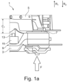
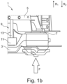
- Figs. 1a and 1b show a first embodiment of an assembly 1 according to the first aspect of the invention in different damping modes.
- Assembly 1 comprises a subframe 3 and a body 5 of a vehicle.
- the assembly 1 also comprises a damping element 7, here a rubber bushing, by means of which the subframe 3 and the body 5 are connected to each other.
- the assembly 1 further comprises a linear actuator 9 which has an actuator housing 11 and an actuating element 13, here in form of a rod which is designed as a screw or spindle.
- the actuator housing 11 is attached to the subframe 3.
- the actuating element 13 By actuating the linear actuator 9, the actuating element 13 can be displaced reciprocally back and forth along a direction R1. In other words, the actuating element 13 (rod) can be extended and retracted by actuating the actuating element 13.
- the actuating element 13 By actuating the actuating element 13 (and thereby especially displacing an end section thereof) accordingly, different damping modes of the damping element 7 can be set, wherein a maximum compressibility of (at least parts of) the damping element 7 is different for at least two of the different damping modes, as described in more detail below.
- Fig. 1a shows the actuating element 13 being retracted (i.e. it is in a first position). With the actuating element 13 being in this position, a first damping mode of the damping element 7 is set.
- the actuating element 13 In the first damping mode, the actuating element 13 is retracted so that a free end of the actuating element 13 is spaced from the body 5 (to which the actuator housing 11 is not attached) by a first clearance C 1 .
- a particular force F which is acting along the direction indicated by the respective arrow in Figs. 1a and 1b is directed from the subframe 3 in the direction of the body 5 (only or substantially) via the damping element 7 while causing a compression of the damping element 7.
- the compression of the damping element 7 absorbs energy introduced by the force F.
- the actuating element 13 has no effect on the compressibility of the damping element 7 during action of the force F in the first damping mode (since even a full compression of the damping element 7 is at least in principle possible by a respective strong force F).
- Fig. 1b shows the actuating element 13 being extended (i.e. it has been moved to a second position). With the actuating element 13 being in this position, a second damping mode of the damping element 7 is set.
- the actuating element 13 In the second damping mode the actuating element 13 is extended so that the free end of the actuating element 13 abuts (or alternatively is spaced by a second clearance, which is less than the first clearance, from) the body 5 (to which the actuator housing is not attached).
- the force F acting on the subframe 3 can be at least partly directed via the actuating element 9 past the damping element 7 in the direction towards the body 5.
- the actuating element 9 being extended a compression of (at least parts of) the damping element 7 as a result of the action of the force F (the same which were assumed in the scenario described with respect to Fig. 1a ) can be avoided or reduced.
- the subframe 3 converges or approaches the body 5 unless the actuating element 13 abuts the body 3.
- the freedom of movement of the subframe 3 relative to the body 5 along the direction R 1 is restricted by the actuating element 13. This is because during action of the force F, the subframe 3 can converge the body 5 only unless the end section of the rod gets in contact with the body 5. Once this happens, the actuating element 13 is in force-transmitting and movement-restricting contact with the body 5. Then a further converging of the subframe 3 in the direction of the body 5 is not possible. It is noted that the actuating element 13 is also in (indirect) contact with the subframe 3 via parts of the linear actuator 9.
- the damping mode of the damping element 7 can be set in that the actuating element 13 is moved between the first and second position in the described manner so as to either allow full or no or less compression of (at least parts of) the damping element 7 upon action of the force F.
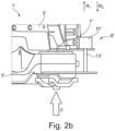
- Figs. 2a and 2b show a second embodiment of an assembly 1' according to the first aspect of the invention in different damping modes.
- the assembly 1' of the second embodiment is similar to the assembly 1 of the first embodiment, which is why features that are the same or identical to features of the assembly 1 of the first embodiment in the assembly 1' of the second embodiment have the same but single dashed reference signs. Furthermore, only the differences between the assemblies 1' and 1 of the second and first embodiments are discussed, while in all other respects the description given for the assembly 1 of the first embodiment also applies here mutatis mutandis.
- the housing 11' is firmly attached to the body 5'.
- the actuating element 13' By actuating the actuating element 13', the actuating element 13' can be displaced reciprocally back and forth along a direction R 2 .
- the actuating element 13' (rod) can be extended and retracted by actuating the actuating element 13'.
- actuating the actuating element 13' (and thereby especially displacing an end section thereof) accordingly different damping modes of the damping element 7' can be set, wherein a maximum compressibility of (at least parts of) the damping element 7' is different for at least two of the different damping modes, likewise as described above.
- Fig. 2a shows the actuating element 13' being retracted (i.e. it is in a first position). With the actuating element 13' being in this position, a first damping mode of the damping element 7' is set.
- a particular force F which is acting along the direction indicated by the respective arrow in Figs. 2a and 2b is directed from the subframe 3' in the direction of the body 5 (only or substantially) via the damping element 7' while causing a compression of the damping element 7'. This is similar as described above with respect to Fig. 1a .
- Fig. 1b shows the actuating element 13' being extended (i.e. it has been moved to a second position). With the actuating element 13' being in this position, a second damping mode of the damping element 7' is set.
- the actuating element 13' In the second damping mode the actuating element 13' is extended so that the free end of the actuating element 13' abuts (or alternatively is spaced by a second clearance, which is less than the first clearance, from) the subframe 5' (to which the actuator housing is not attached). This is similar as described above with respect to Fig. 1b .
- the actuating element 13' is in force-transmitting and movement-restricting contact with the subframe 3'. Then a further converging between the subframe 3' and the body 5' is not possible. Furthermore, once said force-transmitting contact is established, the force F is then directed from the subframe 3' in the direction of the body 5' at least partially past the damping element 7' via the actuating element 13'.
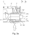
- Figs. 3a and 3b show a third embodiment of an assembly 1" according to the first aspect of the invention in different damping modes.
- the assembly 1" of the third embodiment is similar to the assembly 1' of the second embodiment, which is why features that are the same or identical to features of the assembly 1' of the second embodiment in the assembly 1" of the third embodiment have the same but double dashed reference signs. Furthermore, only the differences between the assemblies 1" and 1' of the third and second embodiments are discussed, while in all other respects the description given for the assembly 1' of the second embodiment also applies here mutatis mutandis.
- actuating elements 13a" and 13b For the assembly 1", two actuating elements 13a" and 13b", a (first) actuating element 13a” and a further (or second) actuating element 13b", each in form of a rod are provided for the linear actuator 9".
- the actuating elements 13a” and 13b” can respectively be designed here as a spindle.
- the housing 11" is firmly attached to the subframe 3".
- the first actuating element 13a” can be displaced back and forth along the direction R 1
- the second actuating element 13b" can be displaced back and forth along the direction R 2 .
- the actuating elements 9a", 9b" can be extended and retracted by actuating the actuating element 13a" and 13b".
- damping modes of the damping element 7" can be set, wherein a maximum compressibility of (at least parts of) the damping element 7" is different for at least two of the different damping modes, likewise as described above.
- Fig. 3a shows the actuating elements 13a" and 13b' being retracted (i.e. they are both in a first position). With the actuating elements 13a" and 13b' being in this position, a first damping mode of the damping element 7" is set.
- the first actuating element 13a" is retracted so that a free end of the first actuating element 13a” is spaced from the body 5 (to which the actuator housing 11" is not attached) by a first clearance C 1 and the second actuating element 13b" is retracted so that a free end of the second actuating element 13b" is spaced from a washer 15" which is attached to the damping element 7" on a side of the subframe 3" facing away from the body 5" by a third clearance C 3 .
- a particular force F which is acting along the direction indicated by the respective arrow in Figs. 3a and 3b is directed from the subframe 3' in the direction of the body 5 (only or substantially) via the damping element 7' while causing a compression of the damping element 7'. This is similar as described above with respect to Fig. 1a .
- Fig. 3b shows the actuating elements 13a" and 13b" being extended (i.e. they both have been moved to a second position).
- the first actuating element 13a" is extended so that the free end of the first actuating element 13a” abuts (or alternatively is spaced by a second clearance, which is less than the first clearance, from) the body 5" (to which the actuator housing 11" is not attached).
- the second actuating element 13b" is extended so that the free end of the second actuating element 13b" abuts (or alternatively is spaced by a fourth clearance, which is less than the third clearance, from) the washer 15".
- the force F acting on the subframe 3" can be at least partly directed via the first actuating element 13a" and/or the second actuating element 13b" past the damping element 7" in the direction towards the body 5'.
- the first actuating element 13a" is in force-transmitting and movement-restricting contact with the body 5'. Then a further converging between the subframe 3" and the body 5" is not possible. Furthermore, a force-transmitting contact is established, so that the force F is then directed from the subframe 3" in the direction of the body 5" at least partially past the damping element 7" via the first actuating element 13a".
- the damping mode of the damping element 7" can be set in that the actuating elements 13a" and 13b" are moved between the positions in the described manner.
Landscapes
- Engineering & Computer Science (AREA)
- Mechanical Engineering (AREA)
- Chemical & Material Sciences (AREA)
- Combustion & Propulsion (AREA)
- Transportation (AREA)
- Physics & Mathematics (AREA)
- Acoustics & Sound (AREA)
- Vibration Prevention Devices (AREA)
Abstract
The present invention relates to an assembly (1) having a damping element (7). The present invention also relates to a method for setting a damping mode of a damping element (7) of such an assembly (1).
Description
- The present invention relates to an assembly having a damping element. The present invention also relates to a method for setting a damping mode of a damping element of such an assembly.
- Conventionally, a vehicle's subframe is typically isolated from the vehicle body by one or more rubber bushings for comfort and noise vibration harshness reasons. The function of the rubber bushing is to isolate the noise and soften the impact from the vehicle's wheels by mounting the subframe to the body in an elastic manner.
- However, on the track, the elastic rubber causes the vehicle dynamics to perform inaccurately. For example, when cornering, the subframe tilts around an x-axis under the torque caused by the left and right anti-roll bar attachments, which exerts a vertical force on the subframe. If the rear-wheel steering is mounted in the subframe, the inclination of the subframe also has a negative effect on steering accuracy.
- If, on the other hand, the subframe is rigidly mounted directly to the body, noise isolation is poor. Shocks and jolts from the wheel are also transferred directly to the body without damping. If the engine is also mounted on the subframe, noise from the engine is also transferred to the body.
- It is therefore the object of the present invention to provide means which make it possible to overcome the problems known from the state of the art.
- The object is achieved by the subject matter of the independent claims. Preferred embodiments and preferred features are specified in the dependent claims and the following description.
- The object is solved according to a first aspect of the invention in that an assembly comprising a subframe and a body of a vehicle which are connected to each other via at least one damping element comprised by the assembly, wherein the assembly comprises at least one linear actuator having at least one actuator housing and at least one actuating element, wherein the actuator housing is attached to the subframe or the body, wherein different damping modes of the damping element can be set by actuating the actuating element, is proposed.
- Thus, an elastic and a rigid connection can be provided interchangeably between the subframe and the body if a force acting on the subframe is selectively directed at least partially past a conventional damping element in the direction of the body. In that the actuating element is actuated, a clearance between the subframe and the body can be adjusted, hence, a compressibility of the damping element can be adjusted, hence, a type of the connection can be set.
- This makes it possible, for example for a sports SUV for multi-purpose use, to provide a connection with the effect of an elastically isolated subframe when driving in town, and a connection with the effect of a rigid or fixed subframe when driving in sports mode or on the racetrack. In other words, it can thus be made possible to reduce the vibrations transferred to the body while still maintaining high steering accuracy.
- Thus, with one and the same assembly it is possible to adapt the degree of damping between the subframe and the body according to the situation in which the vehicle is used. In certain driving situations, high stiffness can provide high motion control, while in other driving situations, low stiffness can improve comfort with respect to vibrations and noise.
- For example, a wheel and/or an engine can be connected to the subframe, and during driving vibrations, noise, shocks and jolts acting on the wheel and/or generated by the engine can in turn act as said force on the subframe.
- Preferably, by moving the actuating element to different positions a convergence of the subframe and the body is or can be controlled and/or a compression of the damping element is or can be controlled.
- For example, the linear actuator may be designed so as to (i) put the actuating element into a first state, especially move the actuating element, especially the free end thereof, to a first position and/or extend the actuating element to a first degree, in which first state the actuating element affects the compressibility of the damping element to a first degree or does not affect the compressibility of the damping element and/or (ii) put the actuating element into a second state, especially move the actuating element, especially the free end thereof, to a second position and/or extend the actuating element to a second degree, in which second state the actuating element affects the compressibility of the damping element, especially to a second degree, which second degree represents a smaller compressibility than the first degree.
- The actuating element may be in permanent direct or indirect force-transmitting contact with the body if the housing is attached to the body. The actuating element may be in permanent direct or indirect force-transmitting contact with the subframe if the housing is attached to the subframe.
- In a preferred embodiment the actuating element extends from the body and/or towards the subframe and/or the actuating element extends from the subframe and/or towards the body.
- Alternatively or in addition, in an embodiment a maximum compressibility of at least parts of the damping element by a relative movement of the subframe in a direction towards the body is different for at least two of the different damping modes.
- For example, the maximum compressibility is observed along a vertical direction and or along a direction pointing from the body to the subframe.
- Alternatively or in addition, in an embodiment in a first a damping mode the actuating element is retracted so that a free end of the actuating element is spaced from the respective one of the subframe and the body to which the actuator housing is not attached by a first clearance.
- In the first damping mode, a transfer of vibrations and noise from the road and possibly from the engine to the body is beneficially reduced. Shocks and jolts can also be reduced.
- For example, in the first damping mode the actuating element has no influence on the compressibility of the damping element.
- In embodiments, in the first damping mode the subframe and the body are elastically coupled to each other.
- In an embodiment the assembly is designed so that the linear actuator moves the actuating element such that it is retracted for setting the first damping mode.
- Preferably, the assembly, especially the linear actuator, is designed such that the actuating element does not restrict, at least in the first damping mode, the freedom of movement of the subframe relative to the body for a movement of the subframe relative to the body which leads to a convergence of the subframe and the body.
- Alternatively or in addition, in an embodiment in the first damping mode, a force acting on the subframe cannot be directed via the actuating element past the damping element in the direction towards the body.
- Alternatively or in addition, in an embodiment in a second damping mode the actuating element is extended so that the free end of the actuating element abuts or is spaced by a second clearance from the respective one of the subframe and the body to which the actuator housing is not attached, wherein the second clearance is less than the first clearance.
- In the second damping mode, high loads from vehicle inertia, road and engine torque can preferably be carried.
- Preferably, when the actuating element is retracted, the extension of the actuating element along a main extension direction of the actuating element, especially outside of the housing, may be smaller compared to the extension of the actuating element along the main extension direction of the actuating element, especially outside of the housing, when the actuating element is extended.
- Preferably, in the second damping mode compression of the damping element (especially at least for a part of the damping element arranged between the body and the subframe), especially substantially, is or can be prevented by the actuating element.
- For example, in the first damping mode a particular force acting on the subframe causes a compression of the damping element of a first compression degree while preferably in the second damping mode the particular force acting on the subframe causes a compression of the damping element of a second compression degree, wherein preferably compared to the first compression degree the second compression degree represents a reduced compression of the damping element. Alternatively or in addition, in the second damping mode the particular force acting on the subframe causes no compression of at least parts of the damping element since the actuating element substantially prevents compression of the damping element.
- For example, in the second damping mode the actuating element has an influence on the compressibility of the damping element.
- In embodiments, in the second damping mode, especially for a particular force acting on the subframe, (i) the actuating element can be brought in force-transmitting and movement-restricting contact with the body and/or the subframe and/or (ii) the subframe and the body are rigidly coupled to each other. A rigid coupling may be established for example in that the actuating element is in a direct or indirect force-fit connection with both, the subframe and the body. In a force-transmitting contact with the body and/or the subframe the particular force acting on the subframe can be at least partially directed via the actuating element in the direction of the body.
- For example, once the force-transmitting contact is established due to a relative movement of the subframe in a direction towards the body, an ongoing relative movement of the subframe towards the body is prevented.
- In an embodiment the assembly is designed so that the linear actuator moves the actuating element such that it is extended for setting the second damping mode.
- Alternatively or in addition, in an embodiment the second damping mode is or can be set in that the actuating element is or can be arranged so as to restrict the freedom of movement of the subframe relative to the body. For example, in the second damping mode, the actuating element restrict a convergence of the subframe and the body.
- For example, a particular force acting on the subframe (A) can, in the first damping mode, be directed from the subframe in the direction of the body via the damping element while compressing the damping element, and/or (B) can, in the second damping mode, be directed from the subframe in the direction of the body at least partially (simultaneously and/or sequentially) past the damping element via the actuating element.
- Preferably, the assembly, especially the linear actuator, is designed such that the actuating element does restrict, at least in the second damping mode, the freedom of movement of the subframe relative to the body for a movement of the subframe relative to the body which leads to a convergence of the subframe and the body.
- Alternatively or in addition, in an embodiment in the second damping mode, a force acting on the subframe can be at least partly directed via the actuating element past the damping element in the direction towards the body.
- Alternatively or in addition, in an embodiment in the first damping mode a further actuating element of the same or another linear actuator is retracted so that a free end of the further actuating element is spaced from a washer attached to the damping element by a third clearance.
- In a preferred embodiment the further actuating element extends from the body and/or towards the washer and/or the further actuating element extends from the subframe and/or towards the washer.
- Preferably, the actuating element and the further actuating element extend in opposite directions.
- The further actuating element can be named as a second actuating element for the ease of differentiating it from the other actuating element, which can be named as a first actuating element.
- The further actuating element may be in permanent direct or indirect force-transmitting contact with the body and/or with the subframe.
- For example, in the first damping mode the further actuating element has no influence on the compressibility of the damping element.
- In embodiments, in the first damping mode the subframe and the washer are elastically coupled to each other.
- In an embodiment the assembly is designed so that the linear actuator (or the another linear actuator) moves the further actuating element such that it is retracted for setting the first damping mode.
- Preferably, the assembly, especially the linear actuator (or the another linear actuator), is designed such that the further actuating element does not restrict, at least in the first damping mode, the freedom of movement of the subframe relative to the washer for a movement of the subframe relative to the washer which leads to an convergence of the subframe and the washer.
- Preferably, in the first damping mode, a force acting on the washer cannot be directed via the further actuating element past the damping element in the direction towards the subframe.
- Alternatively or in addition, in an embodiment the washer is attached to the damping element or a part thereof on a side of the subframe facing away from the body.
- This way it is possible to adapt the force necessary which lead to a relative movement of the body in form of a convergence of the body and the subframe.
- Alternatively or in addition, in an embodiment in the second damping mode the further actuating element is extended so that the free end of the further actuating element abuts or is spaced by a fourth clearance from the washer, wherein the fourth clearance is less than the third clearance.
- The washer preferably provides an abutting surface for the further actuating element.
- Preferably, when the further actuating element is retracted, the extension of the further actuating element along a main extension direction of the further actuating element, especially outside of the housing, may be smaller compared to the extension of the further actuating element along the main extension direction of the further actuating element, especially outside of the housing, when the further actuating element is extended.
- Preferably, in the second damping mode compression of the damping element (especially at least for a part of the damping element arranged not between the body and the subframe), especially substantially, is or can be prevented by the further actuating element (i.e. the second actuating element).
- Preferably, in the second damping mode compression of the damping element, especially substantially, is or can be prevented by the actuating element (i.e. the first actuating element) and the further actuating element (i.e. the second actuating element).
- For example, in the first damping mode a particular force acting on the washer causes a compression of the damping element of a first compression degree while preferably in the second damping mode the particular force acting on the washer causes a compression of the damping element of a second compression degree, wherein preferably compared to the first compression degree the second compression degree represents a reduced compression of the damping element. Alternatively or in addition, in the second damping mode the particular force acting on the washer causes no compression of at least parts of the damping element since the further actuating element substantially prevents compression of the damping element.
- For example, in the second damping mode the further actuating element has an influence on the compressibility of the damping element.
- In embodiments, in the second damping mode, especially for a particular force acting on the subframe and/or the washer, (i) the further actuating element can be brought in force-transmitting and movement-restricting contact with the washer and/or the subframe and/or (ii) the subframe and the washer are rigidly coupled to each other. A rigid coupling may be established for example in that the further actuating element is in a direct or indirect force-fit connection with both, the subframe and the washer. In a force-transmitting contact with the subframe and/or the washer the particular force acting on the washer can be at least partially directed via the further actuating element in the direction of the subframe.
- For example, once the force-transmitting contact is established due to a relative movement of the subframe in a direction towards the washer, an ongoing relative movement of the subframe towards the washer is prevented.
- In an embodiment the assembly is designed so that the linear actuator (or the another linear actuator) moves the further actuating element such that it is extended for setting the second damping mode.
- Alternatively or in addition, in an embodiment the second damping mode is or can be set in that the further actuating element is or can be arranged so as to restrict the freedom of movement of the subframe relative to the washer. For example, in the second damping mode, the further actuating element restrict a convergence of the subframe and the washer.
- For example, a particular force acting on the washer (A) can, in the first damping mode, be directed from the washer in the direction of the subframe via the damping element while compressing the damping element, and/or (B) can, in the second damping mode, be directed from the washer in the direction of the subframe at least partially (simultaneously and/or sequentially) past the damping element via the further actuating element.
- Preferably, the assembly, especially the linear actuator (or the another linear actuator), is designed such that the further actuating element does restrict, at least in the second damping mode, the freedom of movement of the subframe relative to the washer for a movement of the subframe relative to the washer which leads to a convergence of the subframe and the washer.
- Alternatively or in addition, in an embodiment in the second damping mode, a force acting on the washer can be at least partly directed via the further actuating element past the damping element in the direction towards the subframe and/or the body.
- Thus, a degree of compressibility of the damping element can be adapted.
- Alternatively or in addition, in an embodiment damping element is a rubber bushing, such as an elastic rubber bushing.
- Alternatively or in addition, in an embodiment the linear actuator is an electric actuator, preferably a linear motor, such as a linear magnetic motor, a pneumatic actuator and/or hydraulic actuator.
- Alternatively or in addition, in an embodiment the actuating element and/or the further actuating element, respectively, is a slider, a rotor, a rod, especially a threaded rod such as a spindle, and/or a screw.
- Alternatively or in addition, in an embodiment the actuator housing is attached to the subframe mount sleeve.
- The object is solved according to a second aspect of the invention in that a method for adjusting a damping mode of at least one damping element, especially a damping element comprised by an assembly according to any one of the preceding claims, by means of which a subframe and a body of a vehicle are connected to each other, the method comprising actuating at least one actuating element of at least one linear actuator having at least one actuator housing, wherein the actuator housing is attached to the subframe or the body, wherein the actuating element is actuated to set a damping mode of the damping element, especially the actuating element is actuated to a retracted position to set a first damping mode and/or to an extended position to set a second damping mode, wherein preferably a maximum compressibility is different for at least two of at least two different damping modes, is proposed.
- All advantages described with respect to the assembly according to the first aspect of the invention also apply accordingly to the method according to the second aspect of the invention. Therefore, reference can be made at this point to the previous explanations.
- The features (especially structural and functional features) described in relation to the assembly according to the first aspect of the invention may also be provided accordingly in each of the parts, steps and relations relevant for the method according to the second aspect of the invention, individually and in any combination, unless the context indicates otherwise.
- The subframe, the body, the damping element and/or the linear actuator may be comprised by an assembly, such as an assembly according to the first aspect of the invention.
- For a better understanding of embodiments of the invention and to show how the same may be carried into effect, reference will now be made, purely by way of example, to the accompanying drawings in which like numerals designate corresponding elements or sections throughout.
- In the accompanying drawings:
- Fig. 1a
- shows a first embodiment of an assembly according to the first aspect of the invention in a first damping mode;
- Fig. 1b
- shows the assembly of
Fig. 1a in a second damping mode; - Fig. 2a
- shows a second embodiment of an assembly according to the first aspect of the invention in a first damping mode;
- Fig. 2b
- shows the assembly of
Fig. 2a in a second damping mode; - Fig. 3a
- shows a third embodiment of an assembly according to the first aspect of the invention in a first damping mode; and
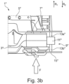
- Fig. 3b
- shows the assembly of
Fig. 3a in a second damping mode. - Various examples of embodiments of the present invention will be explained in more detail by virtue of the following embodiments illustrated in the figures and/or described below.
-
Figs. 1a and1b show a first embodiment of anassembly 1 according to the first aspect of the invention in different damping modes. -
Assembly 1 comprises asubframe 3 and abody 5 of a vehicle. Theassembly 1 also comprises a dampingelement 7, here a rubber bushing, by means of which thesubframe 3 and thebody 5 are connected to each other. - The
assembly 1 further comprises alinear actuator 9 which has anactuator housing 11 and anactuating element 13, here in form of a rod which is designed as a screw or spindle. Theactuator housing 11 is attached to thesubframe 3. - By actuating the
linear actuator 9, theactuating element 13 can be displaced reciprocally back and forth along a direction R1. In other words, the actuating element 13 (rod) can be extended and retracted by actuating theactuating element 13. By actuating the actuating element 13 (and thereby especially displacing an end section thereof) accordingly, different damping modes of the dampingelement 7 can be set, wherein a maximum compressibility of (at least parts of) the dampingelement 7 is different for at least two of the different damping modes, as described in more detail below. -
Fig. 1a shows theactuating element 13 being retracted (i.e. it is in a first position). With theactuating element 13 being in this position, a first damping mode of the dampingelement 7 is set. - In the first damping mode, the
actuating element 13 is retracted so that a free end of theactuating element 13 is spaced from the body 5 (to which theactuator housing 11 is not attached) by a first clearance C1. A particular force F which is acting along the direction indicated by the respective arrow inFigs. 1a and1b is directed from thesubframe 3 in the direction of the body 5 (only or substantially) via the dampingelement 7 while causing a compression of the dampingelement 7. The compression of the dampingelement 7 absorbs energy introduced by the force F. Thus, theactuating element 13 has no effect on the compressibility of the dampingelement 7 during action of the force F in the first damping mode (since even a full compression of the dampingelement 7 is at least in principle possible by a respective strong force F). -
Fig. 1b shows theactuating element 13 being extended (i.e. it has been moved to a second position). With theactuating element 13 being in this position, a second damping mode of the dampingelement 7 is set. - In the second damping mode the
actuating element 13 is extended so that the free end of theactuating element 13 abuts (or alternatively is spaced by a second clearance, which is less than the first clearance, from) the body 5 (to which the actuator housing is not attached). - In the second damping mode, the force F acting on the
subframe 3 can be at least partly directed via theactuating element 9 past the dampingelement 7 in the direction towards thebody 5. Thus, with theactuating element 9 being extended a compression of (at least parts of) the dampingelement 7 as a result of the action of the force F (the same which were assumed in the scenario described with respect toFig. 1a ) can be avoided or reduced. - In the case in which the second damping mode is set, when the force F is acting along the direction indicated by the respective arrow on the
subframe 3, thesubframe 3 converges or approaches thebody 5 unless theactuating element 13 abuts thebody 3. Hence, the freedom of movement of thesubframe 3 relative to thebody 5 along the direction R1 is restricted by theactuating element 13. This is because during action of the force F, thesubframe 3 can converge thebody 5 only unless the end section of the rod gets in contact with thebody 5. Once this happens, theactuating element 13 is in force-transmitting and movement-restricting contact with thebody 5. Then a further converging of thesubframe 3 in the direction of thebody 5 is not possible. It is noted that theactuating element 13 is also in (indirect) contact with thesubframe 3 via parts of thelinear actuator 9. - Once said force-transmitting contact (i.e. at least an indirect connection of the
subframe 3 and thebody 5 via the actuating element 13) is established, thesubframe 3 and thebody 5 is rigidly coupled to each other and the force F is then directed from thesubframe 3 in the direction of thebody 5 at least partially past the dampingelement 7 via theactuating element 13. By adapting the extent to which theactuating element 13 is extended is changed, the compressibility of the damping element 7 (i.e. the possible amount to which the dampingelement 7 can be compressed) by action of the force F can be controlled, hence, the degree of damping, hence the damping mode of the dampingelement 7. - Thus, the damping mode of the damping
element 7 can be set in that theactuating element 13 is moved between the first and second position in the described manner so as to either allow full or no or less compression of (at least parts of) the dampingelement 7 upon action of the force F. -
Figs. 2a and2b show a second embodiment of an assembly 1' according to the first aspect of the invention in different damping modes. - The assembly 1' of the second embodiment is similar to the
assembly 1 of the first embodiment, which is why features that are the same or identical to features of theassembly 1 of the first embodiment in the assembly 1' of the second embodiment have the same but single dashed reference signs. Furthermore, only the differences between theassemblies 1' and 1 of the second and first embodiments are discussed, while in all other respects the description given for theassembly 1 of the first embodiment also applies here mutatis mutandis. - For the assembly 1', the housing 11' is firmly attached to the body 5'. By actuating the actuating element 13', the actuating element 13' can be displaced reciprocally back and forth along a direction R2. In other words, the actuating element 13' (rod) can be extended and retracted by actuating the actuating element 13'. By actuating the actuating element 13' (and thereby especially displacing an end section thereof) accordingly, different damping modes of the damping element 7' can be set, wherein a maximum compressibility of (at least parts of) the damping element 7' is different for at least two of the different damping modes, likewise as described above.
-
Fig. 2a shows the actuating element 13' being retracted (i.e. it is in a first position). With the actuating element 13' being in this position, a first damping mode of the damping element 7' is set. - In the first damping mode, a particular force F which is acting along the direction indicated by the respective arrow in
Figs. 2a and2b is directed from the subframe 3' in the direction of the body 5 (only or substantially) via the damping element 7' while causing a compression of the damping element 7'. This is similar as described above with respect toFig. 1a . -
Fig. 1b shows the actuating element 13' being extended (i.e. it has been moved to a second position). With the actuating element 13' being in this position, a second damping mode of the damping element 7' is set. - In the second damping mode the actuating element 13' is extended so that the free end of the actuating element 13' abuts (or alternatively is spaced by a second clearance, which is less than the first clearance, from) the subframe 5' (to which the actuator housing is not attached). This is similar as described above with respect to
Fig. 1b . - Thus, once the free end of the actuating element 13' abuts the subframe 5' the actuating element 13' is in force-transmitting and movement-restricting contact with the subframe 3'. Then a further converging between the subframe 3' and the body 5' is not possible. Furthermore, once said force-transmitting contact is established, the force F is then directed from the subframe 3' in the direction of the body 5' at least partially past the damping element 7' via the actuating element 13'.
-
Figs. 3a and3b show a third embodiment of anassembly 1" according to the first aspect of the invention in different damping modes. - The
assembly 1" of the third embodiment is similar to the assembly 1' of the second embodiment, which is why features that are the same or identical to features of the assembly 1' of the second embodiment in theassembly 1" of the third embodiment have the same but double dashed reference signs. Furthermore, only the differences between theassemblies 1" and 1' of the third and second embodiments are discussed, while in all other respects the description given for the assembly 1' of the second embodiment also applies here mutatis mutandis. - For the
assembly 1", two actuatingelements 13a" and 13b", a (first) actuatingelement 13a" and a further (or second) actuatingelement 13b", each in form of a rod are provided for thelinear actuator 9". Theactuating elements 13a" and 13b" can respectively be designed here as a spindle. Thehousing 11" is firmly attached to thesubframe 3". By actuating theactuating element 13a" and 13b", thefirst actuating element 13a" can be displaced back and forth along the direction R1 and thesecond actuating element 13b" can be displaced back and forth along the direction R2. In other words, the actuating elements 9a", 9b" can be extended and retracted by actuating theactuating element 13a" and 13b". - By actuating the
actuating elements 13a" and 13b" (and thereby especially displacing an end section of each one of theactuating elements 13a" and 13b") accordingly, different damping modes of the dampingelement 7" can be set, wherein a maximum compressibility of (at least parts of) the dampingelement 7" is different for at least two of the different damping modes, likewise as described above. -
Fig. 3a shows theactuating elements 13a" and 13b' being retracted (i.e. they are both in a first position). With theactuating elements 13a" and 13b' being in this position, a first damping mode of the dampingelement 7" is set. - In the first damping mode, the
first actuating element 13a" is retracted so that a free end of thefirst actuating element 13a" is spaced from the body 5 (to which theactuator housing 11" is not attached) by a first clearance C1 and thesecond actuating element 13b" is retracted so that a free end of thesecond actuating element 13b" is spaced from awasher 15" which is attached to the dampingelement 7" on a side of thesubframe 3" facing away from thebody 5" by a third clearance C3. - In the first damping mode, a particular force F which is acting along the direction indicated by the respective arrow in
Figs. 3a and3b is directed from the subframe 3' in the direction of the body 5 (only or substantially) via the damping element 7' while causing a compression of the damping element 7'. This is similar as described above with respect toFig. 1a . -
Fig. 3b shows theactuating elements 13a" and 13b" being extended (i.e. they both have been moved to a second position). In the second damping mode thefirst actuating element 13a" is extended so that the free end of thefirst actuating element 13a" abuts (or alternatively is spaced by a second clearance, which is less than the first clearance, from) thebody 5" (to which theactuator housing 11" is not attached). In the second damping mode thesecond actuating element 13b" is extended so that the free end of thesecond actuating element 13b" abuts (or alternatively is spaced by a fourth clearance, which is less than the third clearance, from) thewasher 15". With theactuating elements 13a" and 13b" being in this position, a second damping mode of the dampingelement 7" is set. - In the second damping mode, the force F acting on the
subframe 3" can be at least partly directed via thefirst actuating element 13a" and/or thesecond actuating element 13b" past the dampingelement 7" in the direction towards the body 5'. - In the case in which the second damping mode is set, when the force F is acting along the direction indicated by the respective arrow on the
subframe 3", thesubframe 3" converges or approaches thebody 5" unless thefirst actuating element 13a" abuts thebody 3". Hence, the freedom of movement of thesubframe 3" relative to thebody 5" along the direction R1 is restricted by thefirst actuating element 13a". Once this happens, thefirst actuating element 13a" is in force-transmitting and movement-restricting contact with thebody 5". Then a further converging of thesubframe 3" in the direction of thebody 5" is not possible. This is similar as described above with respect toFig. 1a . Furthermore, when the force F is acting along the direction indicated by the respective arrow on thesubframe 3", thewasher 15" converges or approaches thesubframe 3" unless thesecond actuating element 13b" abuts thewasher 15". Hence, the freedom of movement of thesubframe 3" relative to thewasher 15" along the direction R1 is restricted by thesecond actuating element 13b". Once this happens, thesecond actuating element 13b" is in force-transmitting and movement-restricting contact with thewasher 15". Then a further converging of thesubframe 3" and thewasher 15" is not possible (but still a further converging of thesubframe 3" and thebody 5", as long as thefirst actuating element 13a" does not yet abutbody 5"). - Thus, once the free end of the
first actuating element 13a" abuts thebody 5" thefirst actuating element 13a" is in force-transmitting and movement-restricting contact with the body 5'. Then a further converging between thesubframe 3" and thebody 5" is not possible. Furthermore, a force-transmitting contact is established, so that the force F is then directed from thesubframe 3" in the direction of thebody 5" at least partially past the dampingelement 7" via thefirst actuating element 13a". - Thus, once the free end of the
second actuating element 13b" abuts thewasher 15" thesecond actuating element 13b" is in force-transmitting and movement-restricting contact with the washer 15'. Then a further compression of parts of the subframe (on the side faced away from thebody 5") is not possible. Furthermore, a force-transmitting contact is established, so that the force F is then directed from thewasher 15" in the direction of thesubframe 3" at least partially past the dampingelement 7" via thesecond actuating element 13b". - Once said force-transmitting contact (i.e. at least an indirect connection of the
subframe 3" and thebody 5" via thefirst actuating element 13a") is established, thesubframe 3" and thebody 5" is rigidly coupled to each other and the force F is then directed from thesubframe 3" in the direction of thebody 5" at least partially past the dampingelement 7" via thefirst actuating element 13a". By adapting the extent to which thesecond actuating element 13b" is extended, the force required so that thefirst actuating element 13a" abuts the body can be controlled. - Or in other words, by adapting the extent to which the
second actuating element 13b" is extended, a particular force is absorbed more or less by virtue of compression parts of the damping element arranged between the washer and the subframe. - Thus, the damping mode of the damping
element 7" can be set in that theactuating elements 13a" and 13b" are moved between the positions in the described manner. -
- 1, 1', 1"
- Assembly
- 3, 3', 3"
- Subframe
- 5, 5', 5"
- Body
- 7, 7', 7"
- Damping element
- 9, 9', 9"
- Linear actuator
- 11, 11', 11"
- Actuator housing
- 13, 13'
- Actuating element
- 13a", 13b"
- Actuating element
- 15"
- Washer
- C1
- First Clearance
- C3
- Third Clearance
- F
- Force
- R1, R2
- Direction
Claims (15)
- Assembly comprising a subframe and a body of a vehicle which are connected to each other via at least one damping element comprised by the assembly, wherein the assembly comprises at least one linear actuator having at least one actuator housing and at least one actuating element, wherein the actuator housing is attached to the subframe or the body, wherein different damping modes of the damping element can be set by actuating the actuating element.
- Assembly according to claim 1, wherein a maximum compressibility of at least parts of the damping element by a relative movement of the subframe in a direction towards the body is different for at least two of the different damping modes.
- Assembly according to any one of the preceding claims, wherein in a first a damping mode the actuating element is retracted so that a free end of the actuating element is spaced from the respective one of the subframe and the body to which the actuator housing is not attached by a first clearance.
- Assembly according to claim 3, wherein in the first damping mode, a force acting on the subframe cannot be directed via the actuating element past the damping element in the direction towards the body.
- Assembly according to any one of the claims 3 to 4, wherein in a second damping mode the actuating element is extended so that the free end of the actuating element abuts or is spaced by a second clearance from the respective one of the subframe and the body to which the actuator housing is not attached, wherein the second clearance is less than the first clearance.
- Assembly according to claim 5, wherein in the second damping mode, a force acting on the subframe can be at least partly directed via the actuating element past the damping element in the direction towards the body.
- Assembly according to any one of the claims 3 to 6, wherein in the first damping mode a further actuating element of the same or another linear actuator is retracted so that a free end of the further actuating element is spaced from a washer attached to the damping element by a third clearance.
- Assembly according to claim 7, wherein the washer is attached to the damping element or a part thereof on a side of the subframe facing away from the body.
- Assembly according to any one of the claims 7 to 8, wherein in the second damping mode the further actuating element is extended so that the free end of the further actuating element abuts or is spaced by a fourth clearance from the washer, wherein the fourth clearance is less than the third clearance.
- Assembly according to claim 9, wherein in the second damping mode, a force acting on the washer can be at least partly directed via the further actuating element past the damping element in the direction towards the subframe and/or the body.
- Assembly according to any one of the preceding claims, wherein the damping element is a rubber bushing, such as an elastic rubber bushing.
- Assembly according to any one of the preceding claims, wherein the linear actuator is an electric actuator, preferably a linear motor, such as a linear magnetic motor, a pneumatic actuator and/or hydraulic actuator.
- Assembly according to any one of the preceding claims, wherein the actuating element and/or the further actuating element, respectively, is a slider, a rotor, a rod, especially a threaded rod such as a spindle, and/or a screw.
- Assembly according to any one of the preceding claims, wherein the actuator housing is attached to the subframe mount sleeve.
- Method for adjusting a damping mode of at least one damping element, especially a damping element comprised by an assembly according to any one of the preceding claims, by means of which a subframe and a body of a vehicle are connected to each other, the method comprising actuating at least one actuating element of at least one linear actuator having at least one actuator housing, wherein the actuator housing is attached to the subframe or the body, wherein the actuating element is actuated to set a damping mode of the damping element, especially the actuating element is actuated to a retracted position to set a first damping mode and/or to an extended position to set a second damping mode, wherein preferably a maximum compressibility of at least parts of the damping element is different for at least two of at least two different damping modes.
Priority Applications (2)
| Application Number | Priority Date | Filing Date | Title |
|---|---|---|---|
| EP23206904.7A EP4549290A1 (en) | 2023-10-31 | 2023-10-31 | Assembly having a damping element, method for setting a damping mode of a damping element of such an assembly |
| CN202411491736.3A CN119283974A (en) | 2023-10-31 | 2024-10-24 | Assembly with a damping element, method for setting a damping mode of a damping element of the assembly |
Applications Claiming Priority (1)
| Application Number | Priority Date | Filing Date | Title |
|---|---|---|---|
| EP23206904.7A EP4549290A1 (en) | 2023-10-31 | 2023-10-31 | Assembly having a damping element, method for setting a damping mode of a damping element of such an assembly |
Publications (1)
| Publication Number | Publication Date |
|---|---|
| EP4549290A1 true EP4549290A1 (en) | 2025-05-07 |
Family
ID=88647458
Family Applications (1)
| Application Number | Title | Priority Date | Filing Date |
|---|---|---|---|
| EP23206904.7A Pending EP4549290A1 (en) | 2023-10-31 | 2023-10-31 | Assembly having a damping element, method for setting a damping mode of a damping element of such an assembly |
Country Status (2)
| Country | Link |
|---|---|
| EP (1) | EP4549290A1 (en) |
| CN (1) | CN119283974A (en) |
Citations (3)
| Publication number | Priority date | Publication date | Assignee | Title |
|---|---|---|---|---|
| DE102004022167A1 (en) * | 2004-05-05 | 2005-12-01 | Contitech Vibration Control Gmbh | Rear axle carrier for use in motor vehicle, has actuators assigned to respective bearing units, and moved horizontally from centre point of bearing of respective unit with respect to carriage base |
| DE102016216524B4 (en) * | 2016-09-01 | 2020-07-02 | Audi Ag | Device for adjusting the trim position in a motor vehicle |
| DE102019131716A1 (en) * | 2019-11-25 | 2021-05-27 | Schaeffler Technologies AG & Co. KG | Subframe for a motor vehicle |
-
2023
- 2023-10-31 EP EP23206904.7A patent/EP4549290A1/en active Pending
-
2024
- 2024-10-24 CN CN202411491736.3A patent/CN119283974A/en active Pending
Patent Citations (3)
| Publication number | Priority date | Publication date | Assignee | Title |
|---|---|---|---|---|
| DE102004022167A1 (en) * | 2004-05-05 | 2005-12-01 | Contitech Vibration Control Gmbh | Rear axle carrier for use in motor vehicle, has actuators assigned to respective bearing units, and moved horizontally from centre point of bearing of respective unit with respect to carriage base |
| DE102016216524B4 (en) * | 2016-09-01 | 2020-07-02 | Audi Ag | Device for adjusting the trim position in a motor vehicle |
| DE102019131716A1 (en) * | 2019-11-25 | 2021-05-27 | Schaeffler Technologies AG & Co. KG | Subframe for a motor vehicle |
Also Published As
| Publication number | Publication date |
|---|---|
| CN119283974A (en) | 2025-01-10 |
Similar Documents
| Publication | Publication Date | Title |
|---|---|---|
| US7320376B2 (en) | Tire wheel structure | |
| EP1364816B1 (en) | Automotive rear suspension system | |
| US7810819B2 (en) | Method and device for damping vibrations | |
| JP2018514440A (en) | Combined spring compensation suspension system | |
| KR101316870B1 (en) | Active roll control system | |
| US11660921B2 (en) | Independent suspension system | |
| CN102361766A (en) | Active electromechanical suspension system for a chassis of a motor vehicle | |
| WO2003037699A3 (en) | Vehicle subframe mounting | |
| JP6091790B2 (en) | Active control suspension | |
| JPH11227434A (en) | Suspension device for automobile | |
| EP4549290A1 (en) | Assembly having a damping element, method for setting a damping mode of a damping element of such an assembly | |
| KR101518886B1 (en) | Active roll control system | |
| KR0185449B1 (en) | Suspension system for a car | |
| CN115519955B (en) | Suspension system and control method thereof, and vehicle | |
| KR20220068550A (en) | Independent Suspension System | |
| US20070045980A1 (en) | Suspension control arm assembly for vehicles | |
| KR101283605B1 (en) | Active roll control system | |
| JP3551630B2 (en) | Rear suspension for vehicles | |
| US20210316569A1 (en) | Axle of a Vehicle | |
| CN118182032A (en) | Rear independent suspension and vehicle having the same | |
| US12311716B2 (en) | Coilover damper with semi trailing arm on body on frame vehicle | |
| KR100527784B1 (en) | engine mounting system for automotive vehicles | |
| US7322589B2 (en) | Stabilizer assembly for a motor vehicle | |
| KR100857361B1 (en) | Car Geometry Control | |
| CN117698362A (en) | Suspension system and vehicle |
Legal Events
| Date | Code | Title | Description |
|---|---|---|---|
| PUAI | Public reference made under article 153(3) epc to a published international application that has entered the european phase |
Free format text: ORIGINAL CODE: 0009012 |
|
| STAA | Information on the status of an ep patent application or granted ep patent |
Free format text: STATUS: REQUEST FOR EXAMINATION WAS MADE |
|
| 17P | Request for examination filed |
Effective date: 20250115 |
|
| AK | Designated contracting states |
Kind code of ref document: A1 Designated state(s): AL AT BE BG CH CY CZ DE DK EE ES FI FR GB GR HR HU IE IS IT LI LT LU LV MC ME MK MT NL NO PL PT RO RS SE SI SK SM TR |