EP4549271A1 - A vehicle safety system for avoiding road disturbances - Google Patents
A vehicle safety system for avoiding road disturbances Download PDFInfo
- Publication number
- EP4549271A1 EP4549271A1 EP23207249.6A EP23207249A EP4549271A1 EP 4549271 A1 EP4549271 A1 EP 4549271A1 EP 23207249 A EP23207249 A EP 23207249A EP 4549271 A1 EP4549271 A1 EP 4549271A1
- Authority
- EP
- European Patent Office
- Prior art keywords
- warning
- vehicle
- main control
- control unit
- ego
- Prior art date
- Legal status (The legal status is an assumption and is not a legal conclusion. Google has not performed a legal analysis and makes no representation as to the accuracy of the status listed.)
- Pending
Links
Images




Classifications
-
- B—PERFORMING OPERATIONS; TRANSPORTING
- B60—VEHICLES IN GENERAL
- B60W—CONJOINT CONTROL OF VEHICLE SUB-UNITS OF DIFFERENT TYPE OR DIFFERENT FUNCTION; CONTROL SYSTEMS SPECIALLY ADAPTED FOR HYBRID VEHICLES; ROAD VEHICLE DRIVE CONTROL SYSTEMS FOR PURPOSES NOT RELATED TO THE CONTROL OF A PARTICULAR SUB-UNIT
- B60W30/00—Purposes of road vehicle drive control systems not related to the control of a particular sub-unit, e.g. of systems using conjoint control of vehicle sub-units
- B60W30/18—Propelling the vehicle
- B60W30/18009—Propelling the vehicle related to particular drive situations
- B60W30/18163—Lane change; Overtaking manoeuvres
-
- B—PERFORMING OPERATIONS; TRANSPORTING
- B60—VEHICLES IN GENERAL
- B60Q—ARRANGEMENT OF SIGNALLING OR LIGHTING DEVICES, THE MOUNTING OR SUPPORTING THEREOF OR CIRCUITS THEREFOR, FOR VEHICLES IN GENERAL
- B60Q1/00—Arrangement of optical signalling or lighting devices, the mounting or supporting thereof or circuits therefor
- B60Q1/26—Arrangement of optical signalling or lighting devices, the mounting or supporting thereof or circuits therefor the devices being primarily intended to indicate the vehicle, or parts thereof, or to give signals, to other traffic
- B60Q1/50—Arrangement of optical signalling or lighting devices, the mounting or supporting thereof or circuits therefor the devices being primarily intended to indicate the vehicle, or parts thereof, or to give signals, to other traffic for indicating other intentions or conditions, e.g. request for waiting or overtaking
- B60Q1/525—Arrangement of optical signalling or lighting devices, the mounting or supporting thereof or circuits therefor the devices being primarily intended to indicate the vehicle, or parts thereof, or to give signals, to other traffic for indicating other intentions or conditions, e.g. request for waiting or overtaking automatically indicating risk of collision between vehicles in traffic or with pedestrians, e.g. after risk assessment using the vehicle sensor data
-
- B—PERFORMING OPERATIONS; TRANSPORTING
- B60—VEHICLES IN GENERAL
- B60Q—ARRANGEMENT OF SIGNALLING OR LIGHTING DEVICES, THE MOUNTING OR SUPPORTING THEREOF OR CIRCUITS THEREFOR, FOR VEHICLES IN GENERAL
- B60Q9/00—Arrangement or adaptation of signal devices not provided for in one of main groups B60Q1/00 - B60Q7/00, e.g. haptic signalling
- B60Q9/008—Arrangement or adaptation of signal devices not provided for in one of main groups B60Q1/00 - B60Q7/00, e.g. haptic signalling for anti-collision purposes
-
- B—PERFORMING OPERATIONS; TRANSPORTING
- B60—VEHICLES IN GENERAL
- B60W—CONJOINT CONTROL OF VEHICLE SUB-UNITS OF DIFFERENT TYPE OR DIFFERENT FUNCTION; CONTROL SYSTEMS SPECIALLY ADAPTED FOR HYBRID VEHICLES; ROAD VEHICLE DRIVE CONTROL SYSTEMS FOR PURPOSES NOT RELATED TO THE CONTROL OF A PARTICULAR SUB-UNIT
- B60W30/00—Purposes of road vehicle drive control systems not related to the control of a particular sub-unit, e.g. of systems using conjoint control of vehicle sub-units
- B60W30/08—Active safety systems predicting or avoiding probable or impending collision or attempting to minimise its consequences
-
- B—PERFORMING OPERATIONS; TRANSPORTING
- B60—VEHICLES IN GENERAL
- B60W—CONJOINT CONTROL OF VEHICLE SUB-UNITS OF DIFFERENT TYPE OR DIFFERENT FUNCTION; CONTROL SYSTEMS SPECIALLY ADAPTED FOR HYBRID VEHICLES; ROAD VEHICLE DRIVE CONTROL SYSTEMS FOR PURPOSES NOT RELATED TO THE CONTROL OF A PARTICULAR SUB-UNIT
- B60W50/00—Details of control systems for road vehicle drive control not related to the control of a particular sub-unit, e.g. process diagnostic or vehicle driver interfaces
- B60W50/08—Interaction between the driver and the control system
- B60W50/14—Means for informing the driver, warning the driver or prompting a driver intervention
-
- B—PERFORMING OPERATIONS; TRANSPORTING
- B60—VEHICLES IN GENERAL
- B60W—CONJOINT CONTROL OF VEHICLE SUB-UNITS OF DIFFERENT TYPE OR DIFFERENT FUNCTION; CONTROL SYSTEMS SPECIALLY ADAPTED FOR HYBRID VEHICLES; ROAD VEHICLE DRIVE CONTROL SYSTEMS FOR PURPOSES NOT RELATED TO THE CONTROL OF A PARTICULAR SUB-UNIT
- B60W50/00—Details of control systems for road vehicle drive control not related to the control of a particular sub-unit, e.g. process diagnostic or vehicle driver interfaces
- B60W50/08—Interaction between the driver and the control system
- B60W50/14—Means for informing the driver, warning the driver or prompting a driver intervention
- B60W2050/143—Alarm means
-
- B—PERFORMING OPERATIONS; TRANSPORTING
- B60—VEHICLES IN GENERAL
- B60W—CONJOINT CONTROL OF VEHICLE SUB-UNITS OF DIFFERENT TYPE OR DIFFERENT FUNCTION; CONTROL SYSTEMS SPECIALLY ADAPTED FOR HYBRID VEHICLES; ROAD VEHICLE DRIVE CONTROL SYSTEMS FOR PURPOSES NOT RELATED TO THE CONTROL OF A PARTICULAR SUB-UNIT
- B60W2510/00—Input parameters relating to a particular sub-units
- B60W2510/20—Steering systems
- B60W2510/205—Steering speed
-
- B—PERFORMING OPERATIONS; TRANSPORTING
- B60—VEHICLES IN GENERAL
- B60W—CONJOINT CONTROL OF VEHICLE SUB-UNITS OF DIFFERENT TYPE OR DIFFERENT FUNCTION; CONTROL SYSTEMS SPECIALLY ADAPTED FOR HYBRID VEHICLES; ROAD VEHICLE DRIVE CONTROL SYSTEMS FOR PURPOSES NOT RELATED TO THE CONTROL OF A PARTICULAR SUB-UNIT
- B60W2510/00—Input parameters relating to a particular sub-units
- B60W2510/20—Steering systems
- B60W2510/207—Oversteer or understeer
-
- B—PERFORMING OPERATIONS; TRANSPORTING
- B60—VEHICLES IN GENERAL
- B60W—CONJOINT CONTROL OF VEHICLE SUB-UNITS OF DIFFERENT TYPE OR DIFFERENT FUNCTION; CONTROL SYSTEMS SPECIALLY ADAPTED FOR HYBRID VEHICLES; ROAD VEHICLE DRIVE CONTROL SYSTEMS FOR PURPOSES NOT RELATED TO THE CONTROL OF A PARTICULAR SUB-UNIT
- B60W2540/00—Input parameters relating to occupants
- B60W2540/18—Steering angle
-
- B—PERFORMING OPERATIONS; TRANSPORTING
- B60—VEHICLES IN GENERAL
- B60W—CONJOINT CONTROL OF VEHICLE SUB-UNITS OF DIFFERENT TYPE OR DIFFERENT FUNCTION; CONTROL SYSTEMS SPECIALLY ADAPTED FOR HYBRID VEHICLES; ROAD VEHICLE DRIVE CONTROL SYSTEMS FOR PURPOSES NOT RELATED TO THE CONTROL OF A PARTICULAR SUB-UNIT
- B60W2554/00—Input parameters relating to objects
- B60W2554/20—Static objects
-
- B—PERFORMING OPERATIONS; TRANSPORTING
- B60—VEHICLES IN GENERAL
- B60W—CONJOINT CONTROL OF VEHICLE SUB-UNITS OF DIFFERENT TYPE OR DIFFERENT FUNCTION; CONTROL SYSTEMS SPECIALLY ADAPTED FOR HYBRID VEHICLES; ROAD VEHICLE DRIVE CONTROL SYSTEMS FOR PURPOSES NOT RELATED TO THE CONTROL OF A PARTICULAR SUB-UNIT
- B60W2756/00—Output or target parameters relating to data
- B60W2756/10—Involving external transmission of data to or from the vehicle
Definitions
- the present disclosure relates to a vehicle safety system adapted to be mounted to an ego vehicle, where the vehicle safety system comprises a main control unit and a steering angle sensor connected to the main control unit.
- Certain situations are related to a driver of a first vehicle noticing an obstacle on or at the road in the road lane where the first vehicle is travelling. That driver then turns to avoid the obstacle, and the first vehicle may then more or less leave its road lane and enter a neighboring road lane.
- a driver of second vehicle travelling behind the first vehicle may not notice the obstacle sufficiently quickly to successfully avoid the target. This may be due to the distance between the vehicles, weather conditions, time of day etc.
- traffic in the neighboring road lane may be disturbed by vehicles avoiding the obstacle.
- a vehicle safety system adapted to be mounted to an ego vehicle, where the vehicle safety system comprises a main control unit and a steering angle sensor connected to the main control unit.
- the steering angle sensor is adapted to detect the rotational direction and angular velocity of steering wheel movements.
- the main control unit is adapted to determine an ego velocity of the ego vehicle, and to determine if a detected first angular velocity of a first steering wheel movement in a first rotational direction exceeds a first threshold when the ego velocity exceeds an ego velocity threshold. If that is the case, the main control unit is adapted to control at least one warning device to issue a warning that at least comprises an initial warning.
- safety systems and/or drivers of other vehicles can receive information about obstacles and take precautionary actions in dependence of how these vehicles are equipped and of the nature of the warning.
- Different types of warnings and different way to convey the warning will be described later.
- the precautionary actions are intended to avoid incidents and accidents and may for example include Automatic Emergency Brake, Automatic Emergency Steering and or audio/visual warnings to a driver.
- the main control unit is adapted to determine if a detected second angular velocity of a second steering wheel movement in a second rotational direction, that is opposite the first rotational direction, exceeds a second threshold and falls below a third threshold within a predefined first time span. If that is the case, the main control unit is adapted to control said warning device to issue a first type warning, and if the detected second angular velocity exceeds the third threshold within the first time span, the main control unit is adapted to control the least one warning device to issue a second type warning.
- the second steering wheel movement follows the first steering wheel movement within a predetermined time.
- the vehicle safety system further comprises a communication unit, where the main control unit is adapted to control the communication unit to issue the warning by means of wireless communication to at least one other vehicle.
- the vehicle safety system comprises a navigation system adapted to determine a geographical position of the vehicle safety system.
- the communication unit is adapted to communicate issued warnings and the present determined geographical position to the remote server via a wireless link.
- the issued warnings can be collected, stored and processed at the remote server, and information regarding these warnings can be communicated in a certain relevant area.
- the communication can for example be directed to vehicle safety systems and can also be in the form of radio broadcasts.
- the main control unit is adapted to control ego vehicle lights to issue the warning by means of emission of lights and/or flashes.
- warnings can be issued as emission of lights and/or flashes from existing vehicle lights, for example brake lights.
- the vehicle safety system comprises at least one environment detection system that is adapted to provide input to the main control unit. If said input is indicative of an approaching vehicle in an adjacent lane, the main control unit is adapted to control at least one warning device to issue a third type warning.
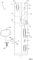
- Figure 1 illustrates a top view of a road scenario where a first vehicle 9 in the form of an ego vehicle 9 is travelling in a road lane 13 and where there is an obstacle 14 ahead of the ego vehicle 9.
- the obstacle can be of any kind such as for example a hole in the road, water, oil spillage and objects such as tire debris, dropped vehicle parts, garbage and the like. Still-standing vehicles can also pose as such obstacles.
- the present disclosure relates to a vehicle safety system 1 adapted to be mounted to the ego vehicle 9.
- the vehicle safety system 1 comprises a main control unit 2 and a steering angle sensor 3 connected to the main control unit 2.
- the steering angle sensor 3 is adapted to detect the rotational direction ⁇ 1, ⁇ 2 and angular velocity v1, v2 of steering wheel movements 4.
- the steering angle sensor 3 is adapted to detect movements of a steering column 17 connected to the steering wheel 15 in a previously well-known manner.
- the steering angle sensor 3 is adapted to detect steering angle movements from an equivalent of the steering column, including but not limited to the previously well-known Steer by Wire system.
- the main control unit 2 is adapted to determine an ego velocity ve of the ego vehicle 9, and to determine if a detected first angular velocity v1 of a first steering wheel movement m1 in a first rotational direction ⁇ 1 exceeds a first threshold th1 when the ego velocity ve exceeds an ego velocity threshold vth. If that is the case, the main control unit 2 is adapted to control at least one warning device 5, 6 to issue a warning wi, w1, w2, w3, where the warning comprises at least an initial warning wi.
- the warning may thus be constituted by one or more separate warnings.
- the ego velocity threshold vth is predetermined and set in a suitable manner such that for example parking maneuvers do not trigger issuance of any warnings. According to some aspects, the ego velocity threshold vth is in the range 0km/h to 70km/h and preferably in the range 30km/h to 50km/h.
- first steering wheel movement m1 in a first rotational direction ⁇ 1 exceeds a first threshold th1 this means that the path 18, 19 of the ego vehicle 9 is changed in certain manner to avoid an obstacle 14 as indicated with a first dashed rectangle 20 in Figure 1 .
- the initial warning wi is issued, and according to some aspects other vehicles 8, 11 can both be noticed that there may be an obstacle in a certain road lane 13 and that one vehicle 9 has made an evasive maneuver.
- safety systems and/or drivers of the other vehicles 8, 11 can receive information about obstacles and take precautionary actions in dependence of how these vehicles are equipped and of the nature of the warning.
- Different types of warnings both the initial warning and subsequent warnings, and different ways to convey the warning will be described later.
- the precautionary actions are intended to avoid incidents and accidents and may for example include Automatic Emergency Brake, Automatic Emergency Steering and or audio/visual warnings to a driver.
- the initial warning wi is issued before further steering wheel movements in another rotational direction, and is thus not indicative of the nature of such steering wheel movements, but would be issued relatively quickly.
- the initial warning wi could according to some aspects be followed by one or more subsequent warnings as will be discussed below.
- the initial warning wi could according to some aspects also be an internal warning that is issued only within the vehicle safety system 1, the warning device being an internal function that for example can be comprised in the main control unit such that the initial warning wi is internally registered.
- the main control unit 2 is adapted to determine if a detected second angular velocity v2 of a second steering wheel movement m2 in a second rotational direction ⁇ 2, that is opposite the first rotational direction ⁇ 1, exceeds a second threshold th2 but falls below a third threshold th3 within a predefined first time span ⁇ t1.
- the main control unit 2 is adapted to control the at least one warning device 5, 6 to issue a first type warning w1, otherwise if the detected second angular velocity v2 exceeds the third threshold th3 within the predefined first time span ⁇ t1, the main control unit 2 is adapted to control the least one warning device 5, 6 to issue a second type warning w2, where the second steering wheel movement ⁇ 2 follows the first steering wheel movement ⁇ 1 within a predetermined time.
- a first type warning w1 is issued.
- the ego vehicle follows a first path 18, indicated by a dashed line, with a relatively slow return to the original path.
- a second type warning w2 is issued.
- the ego vehicle follows a second path 19, indicated with a dash-dotted line, with a relatively quick return to the original path.
- the second path 19 may indicate that there may be an approaching vehicle 11 in an adjacent road lane 25 that forces a quick return, or reckless/mischievous driving that does not necessarily mean that there is an obstacle 14 present.
- the vehicle safety system 1 comprises a communication unit 5, where the main control unit 2 is adapted to control the communication unit 5 to issue the warning wi, w1, w2, w3 by means of wireless communication 7 to at least one other vehicle 8, 11.
- said other vehicle In order to be able to receive the warning wi, w1, w2, w3, said other vehicle must also be equipped with a wireless communication unit. This means that vehicle safety systems 1' present in other vehicles 8 can be informed of the issued warning and possibly receive information regarding the obstacle 14, enabling that vehicle safety systems 1' to take necessary precautionary actions as exemplified above.
- the vehicle safety system 1 comprises a navigation system 12 adapted to determine a geographical position of the vehicle safety system 1, where the communication unit 5 is adapted to communicate issued warnings wi, w1, w2, w3 and the present determined geographical position to the remote server 160 via a wireless link 162.
- the issued warnings wi, w1, w2, w3 can be collected, stored and processed at the remote server 160, and information regarding these warnings can be communicated in a certain relevant area.
- the communication can for example be directed to vehicle safety systems and can also be in the form of radio broadcasts. If acquired, information regarding the position and estimated extension of the obstacle 14 also can be communicated. Examples of this will be discussed later.
- the main control unit 2 is adapted to control ego vehicle lights 6 to issue the warning wi, w1, w2 by means of emission of lights L and/or flashes F.
- the at least one warning device may be a device not only being adapted for issuing warnings in accordance with the present disclosure, but being adapted for other tasks as well.
- warnings can be issued as emission of lights L and/or flashes F from existing vehicle lights, for example brake lights 6. This can be done alone or in combination with communication of issued warnings via a communication unit as describe above.
- the vehicle safety system 1 comprises at least one environment detection system 10 that is adapted to provide input to the main control unit 2, and if said input is indicative of an approaching vehicle 11 in an adjacent lane, the main control unit 2 is adapted to control at least one warning device 5, 6 to issue a third type warning w3.
- the environment detection system 10 can for example be of the type radar, Lidar, and/or camera etc.
- the third type warning w3 can be of similar type as the second type warning w2, but the third type warning w3 is preferably indicative of a lowered risk for reckless/mischievous driving that does not necessarily mean that there is an obstacle 14 present.
- the environment detection system 10 may be adapted to determine the presence of an obstacle 14, which also can constitute input for determining that the third type warning w3 is to be issued.
- a subsequent warning w1, w2, w3 is issued when the driver 16 of the ego vehicle 9 has performed both a first steering wheel movement m1 in a first rotational direction ⁇ 1 and a second steering wheel movement m2 in a second rotational direction ⁇ 2, opposite the first rotational direction ⁇ 1.
- This subsequent warning follows the initial warning.
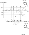
- Figure 8A and Figure 8B show steering wheel angular velocity versus time.
- Figure 8A and Figure 8B show the ego vehicle 9 following an initial general path 24 including the start of an evasive maneuver where a first time t1 occurs when the when the first angular velocity v1 exceeds the first threshold th1 and a second time t2 occurs when the first steering wheel movement m1 in the first rotational direction ⁇ 1 changes to the second steering wheel movement m2 in the second rotational direction ⁇ 2.
- a number of alternatives are shown as illustrative examples.
- the second angular velocity v2 increases and passes both the second threshold th2 and the third threshold 3 without decreasing, which may be the case for a small obstacle 14, the evasive maneuver being relative quick.
- All illustrated paths 18, 18', 19, 23 end by the second angular velocity v2 decreasing and the second steering wheel movement m2 in the second rotational direction ⁇ 2 changing to the first steering wheel movement m1 in the first rotational direction ⁇ 1, enabling the ego vehicle to resume its original course at a fifth time t5.
- the third path 23 may pass the second threshold th2 but not the third threshold th3.
- the second time t2 may according to some aspects be used to indicate a start point of an obstacle extension estimation 22.
- An end point may for example be associated with that the second angular velocity v2 decreases after having exceeded the second threshold th2 two times within the first time span ⁇ t1.
- This is exemplified at a fourth time t4 for the alternative first path 18' in Figure 18A and for the second path 19 in Figure 8B .
- Vehicle position coordinates such as GPS coordinates and/or vehicle size data may also be used when the obstacle extension estimation 22 is determined.
- the first time span ⁇ t1 should be set suitably such that a variety of evasive maneuvers can occur within that first time span ⁇ t1.
- the first time span ⁇ t1 may start at any suitable time, for example at the first time t1 as indicated in Figure 8A and Figure 8B . This is of course only an example.
- the communication unit 5 may according to some aspects be connected via wireless link 162 to a remote server 160, which in turn may be comprised in a cloud-based resource 161 or remote network.
- This server 160 and network may be configured to assist the main control unit 2 in performing various operations as well as storing and evaluating issued warnings w1, w2, w3 over time, collected from different vehicle safety systems 1.
- Some parts of the functionality of the main control unit 2 may be comprised in a remote server 160 or cloud-based resource 161.
- the communication unit 5 may be arranged to communicate 162 with a cellular communication system 163.
- This communication system 163 may, e.g., be a third generation partnership program (3GPP) defined access network like the fourth generation (4G) or the fifth generation (5G) access networks.
- the access network may provide access to remote networks and other resources such as, e.g., the Internet 161.
- the present disclosure also relates to a remote server 160 adapted to collect data from a plurality of vehicle safety systems 1 as described herein, and to determine if issued warnings w1, w2, w3 from different vehicle safety systems 1, 1' are associated with geographical positions within a common limited area 30.
- the issued warnings w1, w2, w3 can be collected, stored and processed at the remote server 160, and information regarding these warnings can be communicated in a certain relevant area, indicating that there is an obstacle 14 present to a certain degree of certainty. Also, information related to the obstacle extension estimation 22 and information regarding if the environment detection system 10 has determined the presence of an obstacle 14 may also be collected, stored and processed at the remote server 160 for the same reasons, such that information regarding the position and estimated extension of the obstacle also can be communicated.
- the communication can for example be directed to vehicle safety systems and can also be in the form of radio broadcasts. It can furthermore be determined whether a certain path such as the second path 19 only is due to reckless/mischievous driving or that an obstacle 14 really is present by processing several issued warnings.
- the remote server 160 is adapted to issue an alert if two or more safety systems 1, 1' are associated with geographical positions within a common limited area 30 when issuing warnings w1, w2, w3. This means that the probability of a real obstacle 14 being present and being the cause of the issued warnings has increased. Also, if the environment detection system 10 has determined the presence of an obstacle 14, the probability of a real obstacle 14 being present and being the cause of the issued warnings has increased.
- the communication unit 5 may according to some aspects be adapted to communicate directly with other safety systems by means of wireless communication 7 that for example may be in the form of at least one of wifi, V2V and V2X communication.
- the vehicle safety system 1 may be adapted to determine at least some of the information described for the remote server 160 above, such that for example the probability of the presence of an obstacle 14, the position and estimated extension of the obstacle 14 also can be communicated.
- the present disclosure also relates to a vehicle 9 comprising the vehicle safety system 1 as described herein.
- the present disclosure also relates to a method for a vehicle safety system 1 used in an ego vehicle 9.
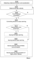
- the method comprises detecting S100 the rotational direction ⁇ 1, ⁇ 2 and angular velocity v1, v2 of steering wheel movements 4 and determining S200 an ego velocity ve of the ego vehicle 9.
- the method further comprises determining S300 if a detected first angular velocity v1 of a first steering wheel movement m1 in a first rotational direction ⁇ 1 exceeds a first threshold th1 when the ego velocity ve exceeds an ego velocity threshold vth, and if that is the case, controlling S400 at least one warning device 5, 6 to issue a warning wi, w1, w2, w3, where the warning comprises at least an initial warning wi.
- the method comprises determining S410 if a detected second angular velocity v2 of a second steering wheel movement m2 in a second rotational direction ⁇ 2, that is opposite the first rotational direction ⁇ 1, exceeds a second threshold th2 and falls below a third threshold th3 within a predefined first time span ⁇ t1. If that is the case, the method comprises controlling S420the least one warning device 5, 6 to issue a first type warning w1. Otherwise, if the detected second angular velocity v2 exceeds the third threshold th3 within the predefined first time span ⁇ t1, the method comprises controlling S430 the least one warning device 5, 6 to issue a second type warning w2.
- the second steering wheel movement ⁇ 2 follows the first steering wheel movement ⁇ 1 within a predetermined time.
- the method further comprises issuing S440 the warning w1, w2, w3 using wireless communication 7 to at least one other vehicle 8, 11, 160.
- the method further comprises issuing S450 the warning using emission of lights L and/or flashes F.
- FIG. 4 schematically illustrates, in terms of a number of functional units, the components of the main control unit 2 according to an embodiment.
- Processing circuitry 410 is provided using any combination of one or more of a suitable central processing unit (CPU), multiprocessor, microcontroller, digital signal processor (DSP), dedicated hardware accelerator, etc., capable of executing software instructions stored in a computer program product, e.g. in the form of a storage medium 430.
- the processing circuitry 410 may further be provided as at least one application specific integrated circuit (ASIC), or field programmable gate array (FPGA).
- ASIC application specific integrated circuit
- FPGA field programmable gate array
- the processing circuitry 410 is configured to cause the main control unit 2 to perform a set of operations, or steps. These operations, or steps, were discussed above in connection to the various radar transceivers and methods.
- the storage medium 430 may store the set of operations
- the processing circuitry 410 may be configured to retrieve the set of operations from the storage medium 430 to cause the main control unit 2 to perform the set of operations.
- the set of operations may be provided as a set of executable instructions.
- the processing circuitry 410 is thereby arranged to execute methods and operations as herein disclosed.
- the storage medium 430 may also comprise persistent storage, which, for example, can be any single one or combination of magnetic memory, optical memory, solid state memory or even remotely mounted memory.
- the main control unit 2 may further comprise a communications interface 420 for communications with at least one other unit.
- the communications interface 420 may comprise one or more transmitters and receivers, comprising analogue and digital components and a suitable number of ports for wired or wireless communication.
- the processing circuitry 410 is adapted to control the general operation of the main control unit 2 e.g. by sending data and control signals to the external unit and the storage medium 430, by receiving data and reports from the external unit, and by retrieving data and instructions from the storage medium 430.
- Other components, as well as the related functionality, of the main control unit 2 are omitted in order not to obscure the concepts presented herein.
- Figure 5 shows a computer program product 510 comprising computer executable instructions 520 arranged on a computer readable medium 530 to execute any of the methods disclosed herein.
- the present disclosure also relates to a main control unit 2 adapted to perform the methods as described herein.
- determining that an angular velocity of steering wheel movements exceeds a threshold can be performed in many ways, for example by means of analyzing the variance of detected steering angles over a moving time window.
- sensor input can be used in order to determine which type of warning that is to be issued, for example accelerometer sensors, map/lane matching sensors, turning signal sensors as well as at least one of brake, clutch and accelerator pedal movement sensors.
- sensors are connected to the main control unit 2 in order to enable the corresponding sensor input to be used to determine which type of warning that is to be issued.
Landscapes
- Engineering & Computer Science (AREA)
- Mechanical Engineering (AREA)
- Automation & Control Theory (AREA)
- Transportation (AREA)
- Human Computer Interaction (AREA)
- Traffic Control Systems (AREA)
Abstract
Description
- The present disclosure relates to a vehicle safety system adapted to be mounted to an ego vehicle, where the vehicle safety system comprises a main control unit and a steering angle sensor connected to the main control unit.
- Certain situations are related to a driver of a first vehicle noticing an obstacle on or at the road in the road lane where the first vehicle is travelling. That driver then turns to avoid the obstacle, and the first vehicle may then more or less leave its road lane and enter a neighboring road lane. A driver of second vehicle travelling behind the first vehicle may not notice the obstacle sufficiently quickly to successfully avoid the target. This may be due to the distance between the vehicles, weather conditions, time of day etc. Furthermore, traffic in the neighboring road lane may be disturbed by vehicles avoiding the obstacle.
- It is therefore an object of the present disclosure to provide means and methods for alleviating institutions where one or more drivers perform evasive maneuvers to avoid one or more obstacles in the road lane.
- This object is achieved by means of a vehicle safety system adapted to be mounted to an ego vehicle, where the vehicle safety system comprises a main control unit and a steering angle sensor connected to the main control unit. The steering angle sensor is adapted to detect the rotational direction and angular velocity of steering wheel movements. The main control unit is adapted to determine an ego velocity of the ego vehicle, and to determine if a detected first angular velocity of a first steering wheel movement in a first rotational direction exceeds a first threshold when the ego velocity exceeds an ego velocity threshold. If that is the case, the main control unit is adapted to control at least one warning device to issue a warning that at least comprises an initial warning.
- In this manner, safety systems and/or drivers of other vehicles can receive information about obstacles and take precautionary actions in dependence of how these vehicles are equipped and of the nature of the warning. Different types of warnings and different way to convey the warning will be described later. The precautionary actions are intended to avoid incidents and accidents and may for example include Automatic Emergency Brake, Automatic Emergency Steering and or audio/visual warnings to a driver.
- According to some aspects, the main control unit is adapted to determine if a detected second angular velocity of a second steering wheel movement in a second rotational direction, that is opposite the first rotational direction, exceeds a second threshold and falls below a third threshold within a predefined first time span. If that is the case, the main control unit is adapted to control said warning device to issue a first type warning, and if the detected second angular velocity exceeds the third threshold within the first time span, the main control unit is adapted to control the least one warning device to issue a second type warning. The second steering wheel movement follows the first steering wheel movement within a predetermined time.
- This means that different types of warnings can be issued in dependence of the path of the ego vehicle when the ego vehicle is returning to the original path.
- According to some aspects, the vehicle safety system further comprises a communication unit, where the main control unit is adapted to control the communication unit to issue the warning by means of wireless communication to at least one other vehicle.
- This means that vehicle safety systems present in other vehicles can be informed of the issued warning and possibly receive information regarding the obstacle, enabling that vehicle safety systems to take necessary precautionary actions.
- According to some aspects, the vehicle safety system comprises a navigation system adapted to determine a geographical position of the vehicle safety system. The communication unit is adapted to communicate issued warnings and the present determined geographical position to the remote server via a wireless link.
- This means that the issued warnings can be collected, stored and processed at the remote server, and information regarding these warnings can be communicated in a certain relevant area. The communication can for example be directed to vehicle safety systems and can also be in the form of radio broadcasts.
- According to some aspects, the main control unit is adapted to control ego vehicle lights to issue the warning by means of emission of lights and/or flashes.
- This means that the warnings can be issued as emission of lights and/or flashes from existing vehicle lights, for example brake lights.
- According to some aspects, the vehicle safety system comprises at least one environment detection system that is adapted to provide input to the main control unit. If said input is indicative of an approaching vehicle in an adjacent lane, the main control unit is adapted to control at least one warning device to issue a third type warning.
- This object is also achieved by means of vehicles, remote servers, methods and main control units that are associated with the above advantages.
- The present disclosure will now be described more in detail with reference to the appended drawings, where:
- Figure 1
- shows a schematic top view of an ego vehicle on a straight road;
- Figure 2
- shows a schematic cut-open part of a vehicle with a vehicle safety system according to the present disclosure;
- Figure 3A-3B
- show steering wheel movements;
- Figure 4
- schematically illustrates a main control unit;
- Figure 5
- schematically illustrates a computer program product;
- Figure 6
- shows flowcharts for methods according to the present disclosure;
- Figure 7
- schematically illustrates different warning types and associated thresholds; and
- Figure 8A-8B
- schematically illustrate steering wheel angular velocity versus time.
- The inventive concept will now be described more fully hereinafter with reference to the accompanying drawings, in which certain embodiments of the inventive concept are shown. This inventive concept may, however, be embodied in many different forms and should not be construed as limited to the embodiments set forth herein; rather, these embodiments are provided by way of example so that this disclosure will be thorough and complete, and will fully convey the scope of the inventive concept to those skilled in the art. Like numbers refer to like elements throughout the description. Any step or feature illustrated by dashed lines should be regarded as optional.
-
Figure 1 illustrates a top view of a road scenario where afirst vehicle 9 in the form of anego vehicle 9 is travelling in aroad lane 13 and where there is anobstacle 14 ahead of theego vehicle 9. The obstacle can be of any kind such as for example a hole in the road, water, oil spillage and objects such as tire debris, dropped vehicle parts, garbage and the like. Still-standing vehicles can also pose as such obstacles. - The present disclosure relates to a
vehicle safety system 1 adapted to be mounted to theego vehicle 9. With reference also toFigure 2 that shows a schematic cut-open part of theego vehicle 9 with adriver 16, thevehicle safety system 1 comprises amain control unit 2 and asteering angle sensor 3 connected to themain control unit 2. As illustrated for an egovehicle steering wheel 15 inFigure 3A and Figure 3B , thesteering angle sensor 3 is adapted to detect the rotational direction ω1, ω2 and angular velocity v1, v2 ofsteering wheel movements 4. For this purpose, according to some aspects, thesteering angle sensor 3 is adapted to detect movements of asteering column 17 connected to thesteering wheel 15 in a previously well-known manner. According to some further aspects, in case of the steering wheel not being connected to a traditional steering column, thesteering angle sensor 3 is adapted to detect steering angle movements from an equivalent of the steering column, including but not limited to the previously well-known Steer by Wire system. - According to the present disclosure, the
main control unit 2 is adapted to determine an ego velocity ve of theego vehicle 9, and to determine if a detected first angular velocity v1 of a first steering wheel movement m1 in a first rotational direction ω1 exceeds a first threshold th1 when the ego velocity ve exceeds an ego velocity threshold vth. If that is the case, themain control unit 2 is adapted to control at least onewarning device - According to some aspects, the ego velocity threshold vth is predetermined and set in a suitable manner such that for example parking maneuvers do not trigger issuance of any warnings. According to some aspects, the ego velocity threshold vth is in the range 0km/h to 70km/h and preferably in the range 30km/h to 50km/h.
- If there is first steering wheel movement m1 in a first rotational direction ω1 exceeds a first threshold th1 this means that the
path ego vehicle 9 is changed in certain manner to avoid anobstacle 14 as indicated with a first dashedrectangle 20 inFigure 1 . By means of the present disclosure, the initial warning wi is issued, and according to some aspectsother vehicles 8, 11 can both be noticed that there may be an obstacle in acertain road lane 13 and that onevehicle 9 has made an evasive maneuver. - In this manner, safety systems and/or drivers of the
other vehicles 8, 11 can receive information about obstacles and take precautionary actions in dependence of how these vehicles are equipped and of the nature of the warning. Different types of warnings, both the initial warning and subsequent warnings, and different ways to convey the warning will be described later. The precautionary actions are intended to avoid incidents and accidents and may for example include Automatic Emergency Brake, Automatic Emergency Steering and or audio/visual warnings to a driver. - The initial warning wi is issued before further steering wheel movements in another rotational direction, and is thus not indicative of the nature of such steering wheel movements, but would be issued relatively quickly. The initial warning wi could according to some aspects be followed by one or more subsequent warnings as will be discussed below. The initial warning wi could according to some aspects also be an internal warning that is issued only within the
vehicle safety system 1, the warning device being an internal function that for example can be comprised in the main control unit such that the initial warning wi is internally registered. - According to some aspects, with reference also to
Figure 7 , themain control unit 2 is adapted to determine if a detected second angular velocity v2 of a second steering wheel movement m2 in a second rotational direction ω2, that is opposite the first rotational direction ω1, exceeds a second threshold th2 but falls below a third threshold th3 within a predefined first time span Δt1. If that is the case, themain control unit 2 is adapted to control the at least onewarning device main control unit 2 is adapted to control the least onewarning device - This means that different types of warnings can be issued in dependence of the path of the
ego vehicle 9 when the ego vehicle is returning to the original path as indicated with a second dashedrectangle 21 inFigure 1 . - If a detected second angular velocity v2 of a second steering wheel movement m2 in a second rotational direction ω2 falls below the third threshold th3, a first type warning w1 is issued. In this case, the ego vehicle follows a
first path 18, indicated by a dashed line, with a relatively slow return to the original path. - Otherwise, if the detected second angular velocity v2 exceeds the third threshold th3, a second type warning w2 is issued. In this case, the ego vehicle follows a
second path 19, indicated with a dash-dotted line, with a relatively quick return to the original path. Thesecond path 19 may indicate that there may be an approachingvehicle 11 in anadjacent road lane 25 that forces a quick return, or reckless/mischievous driving that does not necessarily mean that there is anobstacle 14 present. There is athird path 23, indicated with a dash-double-dotted line, that indicates a relativelysmall obstacle 14 or reckless/mischievous driving. Examples of thesepaths - According to some aspects, the
vehicle safety system 1 comprises acommunication unit 5, where themain control unit 2 is adapted to control thecommunication unit 5 to issue the warning wi, w1, w2, w3 by means ofwireless communication 7 to at least oneother vehicle 8, 11. In order to be able to receive the warning wi, w1, w2, w3, said other vehicle must also be equipped with a wireless communication unit. This means that vehicle safety systems 1' present in other vehicles 8 can be informed of the issued warning and possibly receive information regarding theobstacle 14, enabling that vehicle safety systems 1' to take necessary precautionary actions as exemplified above. - According to some aspects, the
vehicle safety system 1 comprises a navigation system 12 adapted to determine a geographical position of thevehicle safety system 1, where thecommunication unit 5 is adapted to communicate issued warnings wi, w1, w2, w3 and the present determined geographical position to theremote server 160 via awireless link 162. - This means that the issued warnings wi, w1, w2, w3 can be collected, stored and processed at the
remote server 160, and information regarding these warnings can be communicated in a certain relevant area. The communication can for example be directed to vehicle safety systems and can also be in the form of radio broadcasts. If acquired, information regarding the position and estimated extension of theobstacle 14 also can be communicated. Examples of this will be discussed later. - According to some aspects, the
main control unit 2 is adapted to controlego vehicle lights 6 to issue the warning wi, w1, w2 by means of emission of lights L and/or flashes F. This means that the at least one warning device may be a device not only being adapted for issuing warnings in accordance with the present disclosure, but being adapted for other tasks as well. - This also means that the warnings can be issued as emission of lights L and/or flashes F from existing vehicle lights, for
example brake lights 6. This can be done alone or in combination with communication of issued warnings via a communication unit as describe above. - According to some aspects, the
vehicle safety system 1 comprises at least oneenvironment detection system 10 that is adapted to provide input to themain control unit 2, and if said input is indicative of an approachingvehicle 11 in an adjacent lane, themain control unit 2 is adapted to control at least onewarning device environment detection system 10 can for example be of the type radar, Lidar, and/or camera etc. The third type warning w3 can be of similar type as the second type warning w2, but the third type warning w3 is preferably indicative of a lowered risk for reckless/mischievous driving that does not necessarily mean that there is anobstacle 14 present. - It is also conceivable that the
environment detection system 10 may be adapted to determine the presence of anobstacle 14, which also can constitute input for determining that the third type warning w3 is to be issued. - In the above examples, a subsequent warning w1, w2, w3 is issued when the
driver 16 of theego vehicle 9 has performed both a first steering wheel movement m1 in a first rotational direction ω1 and a second steering wheel movement m2 in a second rotational direction ω2, opposite the first rotational direction ω1. This subsequent warning follows the initial warning. - A number of examples of paths is illustrated in
Figure 8A andFigure 8B , showing steering wheel angular velocity versus time.Figure 8A andFigure 8B show theego vehicle 9 following an initialgeneral path 24 including the start of an evasive maneuver where a first time t1 occurs when the when the first angular velocity v1 exceeds the first threshold th1 and a second time t2 occurs when the first steering wheel movement m1 in the first rotational direction ω1 changes to the second steering wheel movement m2 in the second rotational direction ω2. Hereafter a number of alternatives are shown as illustrative examples. - In
Figure 8A , for thefirst path 18, the second angular velocity v2 increases and decreases until it reaches a zero value a third time t3. Here thefirst path 18 continues parallel to theobstacle 14, and the angular velocity may pass a zero value one or more times during this parallel passage, and then the second angular velocity v2 increases again, passing the second threshold th2 but not the third threshold th3. - There in an alternative first path 18', indicated with a dotted line, where the second angular velocity v2 increases and decreases but does not reach a zero value before starting to increase again.
- In
Figure 8B , for thesecond path 19, the second angular velocity v2 increases and decreases until it reaches a zero value a third time t3. At the third time t3, the second angular velocity v2 increases again, passing both the second threshold th2 and the third threshold th3. - For the
third path 23, the second angular velocity v2 increases and passes both the second threshold th2 and thethird threshold 3 without decreasing, which may be the case for asmall obstacle 14, the evasive maneuver being relative quick. - All illustrated
paths - The above examples only illustrate some examples of evasive maneuvers, many other alternatives of course being possible. For example, the
third path 23 may pass the second threshold th2 but not the third threshold th3. - The second time t2 may according to some aspects be used to indicate a start point of an
obstacle extension estimation 22. An end point may for example be associated with that the second angular velocity v2 decreases after having exceeded the second threshold th2 two times within the first time span Δt1. This is exemplified at a fourth time t4 for the alternative first path 18' in Figure 18A and for thesecond path 19 inFigure 8B . This does not cover the case for thethird path 23, and other ways to define a start point and end point of theobstacle extension estimation 22 may of course be devised. Vehicle position coordinates, such as GPS coordinates and/or vehicle size data may also be used when theobstacle extension estimation 22 is determined. - The first time span Δt1 should be set suitably such that a variety of evasive maneuvers can occur within that first time span Δt1. The first time span Δt1 may start at any suitable time, for example at the first time t1 as indicated in
Figure 8A andFigure 8B . This is of course only an example. - The
communication unit 5 may according to some aspects be connected viawireless link 162 to aremote server 160, which in turn may be comprised in a cloud-basedresource 161 or remote network. Thisserver 160 and network may be configured to assist themain control unit 2 in performing various operations as well as storing and evaluating issued warnings w1, w2, w3 over time, collected from differentvehicle safety systems 1. Some parts of the functionality of themain control unit 2 may be comprised in aremote server 160 or cloud-basedresource 161. - For this reason, the
communication unit 5 may be arranged to communicate 162 with acellular communication system 163. Thiscommunication system 163 may, e.g., be a third generation partnership program (3GPP) defined access network like the fourth generation (4G) or the fifth generation (5G) access networks. The access network may provide access to remote networks and other resources such as, e.g., theInternet 161. - The present disclosure also relates to a
remote server 160 adapted to collect data from a plurality ofvehicle safety systems 1 as described herein, and to determine if issued warnings w1, w2, w3 from differentvehicle safety systems 1, 1' are associated with geographical positions within a commonlimited area 30. - As mentioned previously, this means that the issued warnings w1, w2, w3 can be collected, stored and processed at the
remote server 160, and information regarding these warnings can be communicated in a certain relevant area, indicating that there is anobstacle 14 present to a certain degree of certainty. Also, information related to theobstacle extension estimation 22 and information regarding if theenvironment detection system 10 has determined the presence of anobstacle 14 may also be collected, stored and processed at theremote server 160 for the same reasons, such that information regarding the position and estimated extension of the obstacle also can be communicated. - The communication can for example be directed to vehicle safety systems and can also be in the form of radio broadcasts. It can furthermore be determined whether a certain path such as the
second path 19 only is due to reckless/mischievous driving or that anobstacle 14 really is present by processing several issued warnings. - According to some aspects, the
remote server 160 is adapted to issue an alert if two ormore safety systems 1, 1' are associated with geographical positions within a commonlimited area 30 when issuing warnings w1, w2, w3. This means that the probability of areal obstacle 14 being present and being the cause of the issued warnings has increased. Also, if theenvironment detection system 10 has determined the presence of anobstacle 14, the probability of areal obstacle 14 being present and being the cause of the issued warnings has increased. - Similarly, if two or more safety systems are associated with geographical positions within the common
limited area 30, or even the communicatedobstacle extension estimation 22, where warnings w1, w2, w3 have been issued previously without any new warnings being issued, the probability of areal obstacle 14 having been present, or still being present, has decreased. the probability of the presence of anobstacle 14 can thus be communicated. - As mentioned previously, the
communication unit 5 may according to some aspects be adapted to communicate directly with other safety systems by means ofwireless communication 7 that for example may be in the form of at least one of wifi, V2V and V2X communication. Thevehicle safety system 1 may be adapted to determine at least some of the information described for theremote server 160 above, such that for example the probability of the presence of anobstacle 14, the position and estimated extension of theobstacle 14 also can be communicated. - The present disclosure also relates to a
vehicle 9 comprising thevehicle safety system 1 as described herein. - With reference to
Figure 6 , the present disclosure also relates to a method for avehicle safety system 1 used in anego vehicle 9. The method comprises detecting S100 the rotational direction ω1, ω2 and angular velocity v1, v2 ofsteering wheel movements 4 and determining S200 an ego velocity ve of theego vehicle 9. The method further comprises determining S300 if a detected first angular velocity v1 of a first steering wheel movement m1 in a first rotational direction ω1 exceeds a first threshold th1 when the ego velocity ve exceeds an ego velocity threshold vth, and if that is the case, controlling S400 at least onewarning device - According to some aspects, the method comprises determining S410 if a detected second angular velocity v2 of a second steering wheel movement m2 in a second rotational direction ω2, that is opposite the first rotational direction ω1, exceeds a second threshold th2 and falls below a third threshold th3 within a predefined first time span Δt1. If that is the case, the method comprises controlling S420the least one
warning device warning device - According to some aspects, the method further comprises issuing S440 the warning w1, w2, w3 using
wireless communication 7 to at least oneother vehicle - According to some aspects, the method further comprises issuing S450 the warning using emission of lights L and/or flashes F.
-
Figure 4 schematically illustrates, in terms of a number of functional units, the components of themain control unit 2 according to an embodiment.Processing circuitry 410 is provided using any combination of one or more of a suitable central processing unit (CPU), multiprocessor, microcontroller, digital signal processor (DSP), dedicated hardware accelerator, etc., capable of executing software instructions stored in a computer program product, e.g. in the form of astorage medium 430. Theprocessing circuitry 410 may further be provided as at least one application specific integrated circuit (ASIC), or field programmable gate array (FPGA). - Particularly, the
processing circuitry 410 is configured to cause themain control unit 2 to perform a set of operations, or steps. These operations, or steps, were discussed above in connection to the various radar transceivers and methods. For example, thestorage medium 430 may store the set of operations, and theprocessing circuitry 410 may be configured to retrieve the set of operations from thestorage medium 430 to cause themain control unit 2 to perform the set of operations. The set of operations may be provided as a set of executable instructions. Thus, theprocessing circuitry 410 is thereby arranged to execute methods and operations as herein disclosed. - The
storage medium 430 may also comprise persistent storage, which, for example, can be any single one or combination of magnetic memory, optical memory, solid state memory or even remotely mounted memory. - The
main control unit 2 may further comprise acommunications interface 420 for communications with at least one other unit. As such, thecommunications interface 420 may comprise one or more transmitters and receivers, comprising analogue and digital components and a suitable number of ports for wired or wireless communication. - The
processing circuitry 410 is adapted to control the general operation of themain control unit 2 e.g. by sending data and control signals to the external unit and thestorage medium 430, by receiving data and reports from the external unit, and by retrieving data and instructions from thestorage medium 430. Other components, as well as the related functionality, of themain control unit 2 are omitted in order not to obscure the concepts presented herein. -
Figure 5 shows acomputer program product 510 comprising computerexecutable instructions 520 arranged on a computerreadable medium 530 to execute any of the methods disclosed herein. - The present disclosure also relates to a
main control unit 2 adapted to perform the methods as described herein. - The present disclosure is not limited to the examples described above, but may vary freely within the scope of the appended claims. For example, determining that an angular velocity of steering wheel movements exceeds a threshold can be performed in many ways, for example by means of analyzing the variance of detected steering angles over a moving time window.
- It should be known that other sensor input can be used in order to determine which type of warning that is to be issued, for example accelerometer sensors, map/lane matching sensors, turning signal sensors as well as at least one of brake, clutch and accelerator pedal movement sensors. Suitably, one or more of these sensors are connected to the
main control unit 2 in order to enable the corresponding sensor input to be used to determine which type of warning that is to be issued.
Claims (14)
- A vehicle safety system (1) adapted to be mounted to an ego vehicle (9), where the vehicle safety system (1) comprises a main control unit (2) and a steering angle sensor (3) connected to the main control unit (2), where the steering angle sensor (3) is adapted to detect the rotational direction (ω1, ω2) and angular velocity (v1, v2) of steering wheel movements (4), characterized in that the main control unit (2) is adapted to determine an ego velocity (ve) of the ego vehicle (9), and to determine if a detected first angular velocity (v1) of a first steering wheel movement (m1) in a first rotational direction (ω1) exceeds a first threshold (th1) when the ego velocity (ve) exceeds an ego velocity threshold (vth), and if that is the case, the main control unit (2) is adapted to control at least one warning device (5, 6) to issue a warning (wi, w1, w2, w3), where the warning comprises at least an initial warning (wi).
- The vehicle safety system (1) according to claim 1, wherein the main control unit (2) is adapted to determine if a detected second angular velocity (v2) of a second steering wheel movement (m2) in a second rotational direction (ω2), that is opposite the first rotational direction (ω1), exceeds a second threshold (th2) and falls below a third threshold (th3) within a predefined first time span (Δt1), and if that is the case, to control said warning device (5, 6) to issue a first type warning (w1), and if the detected second angular velocity (v2) exceeds the third threshold (th3) within the first time span (Δt1), the main control unit (2) is adapted to control the least one warning device (5, 6) to issue a second type warning (w2), where the second steering wheel movement (ω2) follows the first steering wheel movement (ω1) within a predetermined time.
- The vehicle safety system (1) according to any one of the claims 1 or 2, further comprising a communication unit (5), where the main control unit (2) is adapted to control the communication unit (5) to issue the warning (wi, w1, w2, w3) by means of wireless communication (7) to at least one other vehicle (8, 11) .
- The vehicle safety system (1) according to claim 3, wherein the vehicle safety system (1) comprises a navigation system (12) adapted to determine a geographical position of the vehicle safety system (1), where the communication unit (5) is adapted to communicate issued warnings (wi, w1, w2, w3) and the present determined geographical position to the remote server (160) via a wireless link (162).
- The vehicle safety system (1) according to any one of the previous claims, wherein the main control unit (2) is adapted to control ego vehicle lights (6) to issue the warning (wi, w1, w2) by means of emission of lights (L) and/or flashes (F).
- The vehicle safety system (1) according to any one of the previous claims, wherein the vehicle safety system (1) comprises at least one environment detection system (10) that is adapted to provide input to the main control unit (2), and if said input is indicative of an approaching vehicle (11) in an adjacent lane, the main control unit (2) is adapted to control at least one warning device (5, 6) to issue a third type warning (w3) .
- A vehicle (9) comprising the vehicle safety system (1) according to any one of the previous claims.
- A remote server (160) adapted to collect data from a plurality of vehicle safety systems (1) according to claim 4, and to determine if issued warnings (w1, w2, w3) from different vehicle safety systems (1, 1') are associated with geographical positions within a common limited area.
- The remote server (160) according to claim 8, wherein the remote server (160) is adapted to issue an alert if two or more safety systems (1, 1') are associated with geographical positions within a common limited area when issuing warnings (w1, w2, w3).
- A method for a vehicle safety system (1) used in an ego vehicle (9), where the method comprisesdetecting (S100) the rotational direction (ω1, ω2) and acceleration (a1, a2) of steering wheel movements (4);determining (S200) an ego velocity (ve) of the ego vehicle (9),
characterized in that the method further comprisesdetermining (S300) if a detected first angular velocity (v1) of a first steering wheel movement (m1) in a first rotational direction (ω1) exceeds a first threshold (th1) when the ego velocity (ve) exceeds an ego velocity threshold (vth);and if that is the case,controlling (S400) at least one warning device (5, 6) to issue a warning (wi, w1, w2, w3), where the warning comprises at least an initial warning (wi). - The method according to claim 10, wherein the method comprisesdetermining (S410) if a detected second angular velocity (v2) of a second steering wheel movement (m2) in a second rotational direction( ω2), that is opposite the first rotational direction (ω1), exceeds a second threshold (th2) and falls below a third threshold (th3) within a predefined first time span (Δt1);and if that is the case,controlling (S420) the least one warning device (5, 6) to issue a first type warning (w1); otherwise, if the detected second angular velocity (v2) exceeds the third threshold (th3) within the predefined first time span (Δt1);controlling (S430) the least one warning device (5, 6) to issue a second type warning (w2), where the second steering wheel movement (ω2) follows the first steering wheel movement (ω1) within a predetermined time.
- The method according to any one of the claims 10 or 11, further comprising issuing (S440) the warning (w1, w2, w3) using wireless communication (7) to at least one other vehicle (8, 11, 160) .
- The method according to any one of the claims 10-12, further comprising issuing (S450) warning using emission of lights (L) and/or flashes (F).
- A main control unit (2) adapted to perform the method according to any one of the claims 10-13,
Priority Applications (2)
| Application Number | Priority Date | Filing Date | Title |
|---|---|---|---|
| EP23207249.6A EP4549271A1 (en) | 2023-11-01 | 2023-11-01 | A vehicle safety system for avoiding road disturbances |
| PCT/EP2024/079028 WO2025093281A1 (en) | 2023-11-01 | 2024-10-15 | A vehicle safety system for avoiding road disturbances |
Applications Claiming Priority (1)
| Application Number | Priority Date | Filing Date | Title |
|---|---|---|---|
| EP23207249.6A EP4549271A1 (en) | 2023-11-01 | 2023-11-01 | A vehicle safety system for avoiding road disturbances |
Publications (1)
| Publication Number | Publication Date |
|---|---|
| EP4549271A1 true EP4549271A1 (en) | 2025-05-07 |
Family
ID=88647286
Family Applications (1)
| Application Number | Title | Priority Date | Filing Date |
|---|---|---|---|
| EP23207249.6A Pending EP4549271A1 (en) | 2023-11-01 | 2023-11-01 | A vehicle safety system for avoiding road disturbances |
Country Status (2)
| Country | Link |
|---|---|
| EP (1) | EP4549271A1 (en) |
| WO (1) | WO2025093281A1 (en) |
Citations (4)
| Publication number | Priority date | Publication date | Assignee | Title |
|---|---|---|---|---|
| DE102008000941A1 (en) * | 2008-04-02 | 2009-10-08 | Robert Bosch Gmbh | Method and device for driver assistance |
| WO2010117308A1 (en) * | 2009-04-07 | 2010-10-14 | Volvo Technology Corporation | Method and system to enhance traffic safety and efficiency for vehicles |
| DE102021200572A1 (en) * | 2020-01-27 | 2021-07-29 | Mitsubishi Electric Corporation | Vehicle collision avoidance apparatus and vehicle collision avoidance method |
| US20220055632A1 (en) * | 2020-08-18 | 2022-02-24 | Hyundai Motor Company | Vehicle and method of controlling the same |
-
2023
- 2023-11-01 EP EP23207249.6A patent/EP4549271A1/en active Pending
-
2024
- 2024-10-15 WO PCT/EP2024/079028 patent/WO2025093281A1/en active Pending
Patent Citations (4)
| Publication number | Priority date | Publication date | Assignee | Title |
|---|---|---|---|---|
| DE102008000941A1 (en) * | 2008-04-02 | 2009-10-08 | Robert Bosch Gmbh | Method and device for driver assistance |
| WO2010117308A1 (en) * | 2009-04-07 | 2010-10-14 | Volvo Technology Corporation | Method and system to enhance traffic safety and efficiency for vehicles |
| DE102021200572A1 (en) * | 2020-01-27 | 2021-07-29 | Mitsubishi Electric Corporation | Vehicle collision avoidance apparatus and vehicle collision avoidance method |
| US20220055632A1 (en) * | 2020-08-18 | 2022-02-24 | Hyundai Motor Company | Vehicle and method of controlling the same |
Also Published As
| Publication number | Publication date |
|---|---|
| WO2025093281A1 (en) | 2025-05-08 |
Similar Documents
| Publication | Publication Date | Title |
|---|---|---|
| CN109964264B (en) | Driver assistance system for a motor vehicle | |
| JP3772838B2 (en) | VEHICLE DRIVE SUPPORT DEVICE AND VEHICLE CONTROL DEVICE | |
| US10053067B2 (en) | Vehicle safety assist system | |
| US9566983B2 (en) | Control arrangement arranged to control an autonomous vehicle, autonomous drive arrangement, vehicle and method | |
| US10304333B2 (en) | Method and vehicle communication system for determining a driving intention for a vehicle | |
| CN106379319B (en) | Automobile auxiliary driving system and control method | |
| US9483059B2 (en) | Method to gain driver's attention for autonomous vehicle | |
| KR102419930B1 (en) | Traffic signal response for autonomous vehicles | |
| US20200148205A1 (en) | Traveling control apparatus, vehicle, and traveling control method | |
| US11479245B2 (en) | Semi-autonomous vehicle control system and method of controlling a semi-autonomous vehicle | |
| JP7680254B2 (en) | Driving Support Devices | |
| US20190054922A1 (en) | Systems and methods for automatically passing vehicles | |
| US11801859B2 (en) | Driver assistance system | |
| CN104252796A (en) | Method for exchanging information between at least two vehicles | |
| CN110816540A (en) | Traffic jam determining method, device and system and vehicle | |
| WO2019150525A1 (en) | Vehicle control device, vehicle, and vehicle control method | |
| US20230294731A1 (en) | Traveling control apparatus for vehicle | |
| CN117901851A (en) | Method for determining whether an automatic collision avoidance steering maneuver should be performed | |
| US20170274815A1 (en) | Autoactive braking lights | |
| JP2011014097A (en) | Risk determination device and risk determination system | |
| JP2018090063A (en) | Vehicle control system | |
| EP4549271A1 (en) | A vehicle safety system for avoiding road disturbances | |
| US20240326788A1 (en) | Driver assistance apparatus | |
| US11767021B2 (en) | Systems and methods for remotely assisting an operator | |
| FR3052418A1 (en) | METHOD AND DEVICE FOR ASSISTING THE DRIVING OF A VEHICLE CIRCULATING ON THE APPROACH OF A CARREFOUR |
Legal Events
| Date | Code | Title | Description |
|---|---|---|---|
| PUAI | Public reference made under article 153(3) epc to a published international application that has entered the european phase |
Free format text: ORIGINAL CODE: 0009012 |
|
| STAA | Information on the status of an ep patent application or granted ep patent |
Free format text: STATUS: THE APPLICATION HAS BEEN PUBLISHED |
|
| AK | Designated contracting states |
Kind code of ref document: A1 Designated state(s): AL AT BE BG CH CY CZ DE DK EE ES FI FR GB GR HR HU IE IS IT LI LT LU LV MC ME MK MT NL NO PL PT RO RS SE SI SK SM TR |
|
| STAA | Information on the status of an ep patent application or granted ep patent |
Free format text: STATUS: REQUEST FOR EXAMINATION WAS MADE |
|
| 17P | Request for examination filed |
Effective date: 20251015 |
|
| GRAP | Despatch of communication of intention to grant a patent |
Free format text: ORIGINAL CODE: EPIDOSNIGR1 |
|
| STAA | Information on the status of an ep patent application or granted ep patent |
Free format text: STATUS: GRANT OF PATENT IS INTENDED |
|
| INTG | Intention to grant announced |
Effective date: 20251216 |
|
| GRAS | Grant fee paid |
Free format text: ORIGINAL CODE: EPIDOSNIGR3 |
|
| GRAA | (expected) grant |
Free format text: ORIGINAL CODE: 0009210 |
|
| STAA | Information on the status of an ep patent application or granted ep patent |
Free format text: STATUS: THE PATENT HAS BEEN GRANTED |