EP4549202A1 - Electric work vehicle including plurality of external charge ports - Google Patents
Electric work vehicle including plurality of external charge ports Download PDFInfo
- Publication number
- EP4549202A1 EP4549202A1 EP24207272.6A EP24207272A EP4549202A1 EP 4549202 A1 EP4549202 A1 EP 4549202A1 EP 24207272 A EP24207272 A EP 24207272A EP 4549202 A1 EP4549202 A1 EP 4549202A1
- Authority
- EP
- European Patent Office
- Prior art keywords
- work vehicle
- charge
- electric work
- preferred
- present
- Prior art date
- Legal status (The legal status is an assumption and is not a legal conclusion. Google has not performed a legal analysis and makes no representation as to the accuracy of the status listed.)
- Pending
Links
Images


















Classifications
-
- B—PERFORMING OPERATIONS; TRANSPORTING
- B60—VEHICLES IN GENERAL
- B60K—ARRANGEMENT OR MOUNTING OF PROPULSION UNITS OR OF TRANSMISSIONS IN VEHICLES; ARRANGEMENT OR MOUNTING OF PLURAL DIVERSE PRIME-MOVERS IN VEHICLES; AUXILIARY DRIVES FOR VEHICLES; INSTRUMENTATION OR DASHBOARDS FOR VEHICLES; ARRANGEMENTS IN CONNECTION WITH COOLING, AIR INTAKE, GAS EXHAUST OR FUEL SUPPLY OF PROPULSION UNITS IN VEHICLES
- B60K1/00—Arrangement or mounting of electrical propulsion units
- B60K1/04—Arrangement or mounting of electrical propulsion units of the electric storage means for propulsion
-
- B—PERFORMING OPERATIONS; TRANSPORTING
- B60—VEHICLES IN GENERAL
- B60L—PROPULSION OF ELECTRICALLY-PROPELLED VEHICLES; SUPPLYING ELECTRIC POWER FOR AUXILIARY EQUIPMENT OF ELECTRICALLY-PROPELLED VEHICLES; ELECTRODYNAMIC BRAKE SYSTEMS FOR VEHICLES IN GENERAL; MAGNETIC SUSPENSION OR LEVITATION FOR VEHICLES; MONITORING OPERATING VARIABLES OF ELECTRICALLY-PROPELLED VEHICLES; ELECTRIC SAFETY DEVICES FOR ELECTRICALLY-PROPELLED VEHICLES
- B60L53/00—Methods of charging batteries, specially adapted for electric vehicles; Charging stations or on-board charging equipment therefor; Exchange of energy storage elements in electric vehicles
- B60L53/10—Methods of charging batteries, specially adapted for electric vehicles; Charging stations or on-board charging equipment therefor; Exchange of energy storage elements in electric vehicles characterised by the energy transfer between the charging station and the vehicle
- B60L53/14—Conductive energy transfer
- B60L53/16—Connectors, e.g. plugs or sockets, specially adapted for charging electric vehicles
-
- B—PERFORMING OPERATIONS; TRANSPORTING
- B60—VEHICLES IN GENERAL
- B60L—PROPULSION OF ELECTRICALLY-PROPELLED VEHICLES; SUPPLYING ELECTRIC POWER FOR AUXILIARY EQUIPMENT OF ELECTRICALLY-PROPELLED VEHICLES; ELECTRODYNAMIC BRAKE SYSTEMS FOR VEHICLES IN GENERAL; MAGNETIC SUSPENSION OR LEVITATION FOR VEHICLES; MONITORING OPERATING VARIABLES OF ELECTRICALLY-PROPELLED VEHICLES; ELECTRIC SAFETY DEVICES FOR ELECTRICALLY-PROPELLED VEHICLES
- B60L50/00—Electric propulsion with power supplied within the vehicle
- B60L50/50—Electric propulsion with power supplied within the vehicle using propulsion power supplied by batteries or fuel cells
- B60L50/60—Electric propulsion with power supplied within the vehicle using propulsion power supplied by batteries or fuel cells using power supplied by batteries
- B60L50/66—Arrangements of batteries
-
- B—PERFORMING OPERATIONS; TRANSPORTING
- B62—LAND VEHICLES FOR TRAVELLING OTHERWISE THAN ON RAILS
- B62D—MOTOR VEHICLES; TRAILERS
- B62D25/00—Superstructure or monocoque structure sub-units; Parts or details thereof not otherwise provided for
- B62D25/08—Front or rear portions
- B62D25/10—Bonnets or lids, e.g. for trucks, tractors, busses, work vehicles
- B62D25/12—Parts or details thereof
-
- B—PERFORMING OPERATIONS; TRANSPORTING
- B60—VEHICLES IN GENERAL
- B60L—PROPULSION OF ELECTRICALLY-PROPELLED VEHICLES; SUPPLYING ELECTRIC POWER FOR AUXILIARY EQUIPMENT OF ELECTRICALLY-PROPELLED VEHICLES; ELECTRODYNAMIC BRAKE SYSTEMS FOR VEHICLES IN GENERAL; MAGNETIC SUSPENSION OR LEVITATION FOR VEHICLES; MONITORING OPERATING VARIABLES OF ELECTRICALLY-PROPELLED VEHICLES; ELECTRIC SAFETY DEVICES FOR ELECTRICALLY-PROPELLED VEHICLES
- B60L2200/00—Type of vehicles
- B60L2200/40—Working vehicles
-
- B—PERFORMING OPERATIONS; TRANSPORTING
- B60—VEHICLES IN GENERAL
- B60Y—INDEXING SCHEME RELATING TO ASPECTS CROSS-CUTTING VEHICLE TECHNOLOGY
- B60Y2200/00—Type of vehicle
- B60Y2200/20—Off-Road Vehicles
- B60Y2200/22—Agricultural vehicles
- B60Y2200/221—Tractors
-
- B—PERFORMING OPERATIONS; TRANSPORTING
- B60—VEHICLES IN GENERAL
- B60Y—INDEXING SCHEME RELATING TO ASPECTS CROSS-CUTTING VEHICLE TECHNOLOGY
- B60Y2200/00—Type of vehicle
- B60Y2200/90—Vehicles comprising electric prime movers
- B60Y2200/91—Electric vehicles
-
- Y—GENERAL TAGGING OF NEW TECHNOLOGICAL DEVELOPMENTS; GENERAL TAGGING OF CROSS-SECTIONAL TECHNOLOGIES SPANNING OVER SEVERAL SECTIONS OF THE IPC; TECHNICAL SUBJECTS COVERED BY FORMER USPC CROSS-REFERENCE ART COLLECTIONS [XRACs] AND DIGESTS
- Y02—TECHNOLOGIES OR APPLICATIONS FOR MITIGATION OR ADAPTATION AGAINST CLIMATE CHANGE
- Y02T—CLIMATE CHANGE MITIGATION TECHNOLOGIES RELATED TO TRANSPORTATION
- Y02T10/00—Road transport of goods or passengers
- Y02T10/60—Other road transportation technologies with climate change mitigation effect
- Y02T10/70—Energy storage systems for electromobility, e.g. batteries
Definitions
- the present invention is directed to an electric vehicle (EV) such as an electric tractor.
- EV electric vehicle
- Electric vehicles are becoming more prevalent as the industry moves from internal combustion engines towards fully electrically powered motors running on battery systems.
- Preferred embodiments of the present invention provide an electric work vehicle such as an EV tractor.
- Preferred embodiments of the present invention provide an electric vehicle.
- An electric work vehicle includes a hood, a battery housing including a battery housing portion that houses a plurality of battery modules, and a plurality of charge ports to connect to an external power source to charge the plurality of battery modules.
- Each of the plurality of charge ports is located at a surface of the hood.
- At least one of the plurality of charge ports can be a DC charge port. At least two of the plurality of charge ports can be DC charge ports. At least three of the plurality of charge ports can be a DC charge ports.
- the electric work vehicle can further include a port cover to cover at least one of the plurality of charge ports.
- the port cover can be connected to a body of the electric work vehicle by a hinge.
- the electric work vehicle can further include a latch to secure the port cover in a closed state.
- At least one of the plurality DC charge ports can be located at a rear portion of the hood. At least one of the plurality of charge ports can be located at an upper surface of the hood. At least one of the plurality of charge ports can extend beyond a main upper surface of the hood.
- the hood can include a sloped portion that extends over at least one of the plurality of charge ports.
- the plurality of charge ports can include a first charge port and a second charge port.
- the first charge port and the second charge port can be mounted on a same side of the hood in a left-right direction of the electric work vehicle, the second charge port can be located closer to a steering wheel or driver's seat of the electric work vehicle than the first charge port, and the first charge port can be shorter than the second charge port in an up-down direction of the electric work vehicle.
- the plurality of charge ports can include a first charge port mounted on a right side of the hood and a second charge port mounted on a left side of the hood.
- the first charge port and the second charge port can be located symmetrically about a centerline of the electric work vehicle.
- Each of the plurality of charge ports can be located at a same height in an up-down direction of the electric work vehicle.
- the electric work vehicle can further include a steering wheel and at least one headlight.
- Each of the plurality of charge ports can be located below an upper edge of the steering wheel in the up-down direction.
- Each of the plurality of charge ports can be located above an upper edge of the at least one headlight in the up-down direction.
- Each of the plurality of charge ports can be located between a rear surface of the hood and a centerline of the hood in a front-rear direction of the electric work vehicle.
- the electric work vehicle can further include a power distribution unit housing that houses a power distribution unit.
- the plurality of charge ports can be located forward of the power distribution unit housing in a front-rear direction of the electric work vehicle.
- the electric work vehicle can further include a service disconnect plug to disconnect an electrical connection to one or more of the plurality of battery modules.
- the service disconnect plug can overlap with the power distribution unit in the front-rear direction of the electric work vehicle.
- the plurality of charge ports can be located forward of the service disconnect plug in the front-rear direction of the electric work vehicle.
- the service disconnect plug can be located on a same side of the vehicle as at least one of the plurality of charge ports.
- the electric work vehicle can further include an opening structured for an operator of the electric work vehicle to enter or exit the electric work vehicle. At least one of the plurality of charge ports can face a same side of the electric work vehicle as the opening.
- At least one of the plurality of charge ports can be an AC charge port. At least one of the plurality of charge ports can be a combination of an AC charge port and a DC charge port. At least one of the plurality of charge ports can include a main DC electrical connection and an auxiliary DC electrical connection.
- Electric vehicles according to preferred embodiments of the present invention may be a tractor or other agricultural vehicle, but any desirable type of electric vehicle is applicable to and usable with preferred embodiments of the present invention.
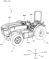
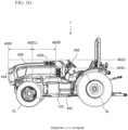
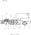
- Fig. 1A to 1I show an electric vehicle 1 according to a preferred embodiment of the present invention.
- Fig. 1A and 1B show perspective views from left and right front ends of the vehicle 1, respectively.
- Fig. 1C shows an isometric view from a left rear end of the vehicle 1.
- Fig. 1D shows an isometric view from a right rear end of the vehicle 1.
- Fig. 1E shows a front view of the vehicle 1.
- Fig. 1F and 1G are side views of the vehicle 1.
- Fig. 1H and 1I are top and bottom views of the vehicle 1, respectively.
- the vehicle 1 includes a left front wheel 2L, a right front wheel 2R, a left rear wheel 4L, and a right rear wheel 4R.
- a vehicle according to the preferred embodiments of the present invention is not specifically limited to four wheels, and may include any appropriate number of wheels.
- a vehicle according to the preferred embodiments may include only three wheels by removing one of the aforementioned four wheels, a fifth wheel (e.g., an additional wheel provided in line with a pair of one of the aforementioned four wheels or a wheel provided at a front or rear of the vehicle, etc.), six total wheels by including a pair of center wheels, and the like.
- tracks can be used instead of wheels.
- the vehicle 1 includes an intermediate frame 6, a battery housing 8 attached to a front portion of the intermediate frame 6, a front frame 10 attached to the battery housing 8, and a rear frame 12 attached a rear portion of the intermediate frame 6, as shown in Fig. 2 , for example.
- a front axle 3 connected to the left front wheel 2L and a right front wheel 2R is connected to and supports the front frame 10
- a rear axle 5 connected to the left rear wheel 4L and the right rear wheel 4R is connected to and supported by the rear frame 12, as shown in Fig. 1I , for example.
- the front axle 3 includes a left axle housing 3L and a right axle housing 3R, as shown in Fig. 1I .
- the left axle housing 3L houses a first electric motor 14 (a left-front-wheel electric motor) that is connected to a first gearing 15 to drive the left front wheel 2L
- the right axle housing 3R houses a second electric motor 16 (a right-front-wheel electric motor) that is connected to a second gearing 17 to drive the right front wheel 2R.
- the first electric motor 14, the second electric motor 16, the first gearing 15, and the second gearing 17 are shown, for example, in Fig. 1J in which the left axle housing 3L and the right axle housing 3R have been removed for illustrative purposes.
- the rear frame 12 includes a first motor housing portion 12-1 to house a third electric motor 18 (a left-rear-wheel electric motor) that is connected to a third gearing 19 to drive the left rear wheel 4L, and a second motor housing portion 12-2 to house a fourth electric motor 20 (a right-rear-wheel electric motor) that is connected to a fourth gearing 21 to drive the right rear wheel 4R.
- a third electric motor 18 a left-rear-wheel electric motor
- a second motor housing portion 12-2 to house a fourth electric motor 20 (a right-rear-wheel electric motor) that is connected to a fourth gearing 21 to drive the right rear wheel 4R.
- the rear frame 12 also includes a third motor housing portion 12-3 to house a fifth electric motor 22 that is connected to a fifth gearing 23 to drive a first electric vehicle component (e.g., a power take-off (PTO)), and a fourth motor housing portion 12-4 to house a sixth electric motor 24 that is connected to a sixth gearing 25 to drive a second electric vehicle component (e.g., a hydraulic system), as shown in Figs. 1J and 2 , for example.
- the third electric motor 18, the fourth electric motor 20, the fifth electric motor 22, and the sixth electric motor 24 are shown, for example, in Fig. 1J in which elements including the rear frame 12 have been removed for illustrative purposes. In the bottom view of Fig. 1J , the sixth electric motor 24 overlaps the third electric motor 18.
- the battery housing 8 includes a first battery housing portion 26, a second battery housing portion 28, a third battery housing portion 30, a fourth battery housing portion 32, and a fifth battery housing portion 34, each of which is shown in Fig. 3 using dashed lines.
- the first battery housing portion 26 and the second battery housing portion 28 are adjacent to each other in a width direction of the vehicle
- the third battery housing portion 30 and the fourth battery housing portion 32 are adjacent to each other in a width direction of the vehicle.
- a width of each of the first battery housing portion 26, the second battery housing portion 28, the third battery housing portion 30, the fourth battery housing portion 32, and the fifth battery housing portion 34 in a width direction of the vehicle is equal or substantially equal.
- Figs. 4 , 5A, and 5B show the battery housing 8 with the battery housing portion covers removed for illustrative purposes.
- the first battery housing portion 26 and the second battery housing portion 28 are included in a first battery housing section 8-1 (a rear battery housing section), the third battery housing portion 30 and the fourth battery housing portion 32 are included in a second battery housing section 8-2 (a forward-upper battery housing section), and the fifth battery housing portion 34 is included in a third battery housing section 8-3 (a forward-lower battery housing section), as shown in Fig. 3 , for example.
- a width of the first battery housing section 8-1 is equal or substantially equal to a width of the second battery housing section 8-2
- a width of the third battery housing section 8-3 is less than a width of the first battery housing section 8-1 and a width of the second battery housing section 8-2.
- a rear surface of the third battery housing section 8-3 is spaced away from a front surface of the first battery housing section 8-1.
- a rear surface of the second battery housing section 8-2 intersects a middle portion of the first battery housing section 8-1 in a front-rear direction of the electric vehicle in a top view and a side view.
- each of the first battery housing portion 26, the second battery housing portion 28, the third battery housing portion 30, the fourth battery housing portion 32, and the fifth battery housing portion 34 includes a plurality of battery housing module compartments, which are each to receive a battery module.
- each of the third battery housing portion 30 and the fourth battery housing portion 32 includes more battery housing module compartments than each of the first battery housing portion 26 and the second battery housing portion 28.
- the fifth battery housing portion 34 includes less battery housing module compartments than each of the first battery housing portion 26 and the second battery housing portion 28.
- Figs. 6A and 6B show, respectively, left and right side views of the intermediate frame 6, the battery housing 8, the front frame 10, and the rear frame 12 shown in Fig. 2 , for example.
- a front portion of the intermediate frame 6 is attached to a rear portion of the battery housing 8, and a rear portion of the intermediate frame 6 is attached to a front portion of the rear frame 12.
- the intermediate frame 6 is located between the battery housing 8 and the rear axle 5 in the front-rear direction of the vehicle 1.
- a chassis of the vehicle 1 can include the intermediate frame 6 and the front frame 10.
- the rear frame 12 can include the first motor housing portion 12-1 to house the third electric motor 18, the second motor housing portion 12-2 to house the fourth electric motor 20, the third motor housing portion 12-3 to house the fifth electric motor 22, and the fourth motor housing portion 12-4 to house the sixth electric motor 24.
- the first motor housing portion 12-1, the second motor housing portion 12-2, the third motor housing portion 12-3, and the fourth motor housing portion 12-4 are preferably located in a rearward direction of the intermediate frame 6. Accordingly, each of the third electric motor 18, the fourth electric motor 20, the fifth electric motor 22, and the sixth electric motor 24 are preferably located rearwardly of the intermediate frame 6 in a front-rear direction of the vehicle 1.
- one or more inverters 13 are connected to, attached on, or supported by the battery housing 8.
- the one or more inverters 13 can include a first inverter 13-1, a second inverter 13-2, a third inverter 13-3, a fourth inverter 13-4, a fifth inverter 13-5, a sixth inverter 13-6, and a seventh inverter 13-7.
- the first inverter 13-1, the third inverter 13-3, the sixth inverter 13-6, and the seventh inverter 13-7 are located on a left side of the battery housing 8.
- the second inverter 13-2, the fourth inverter 13-4, and the fifth inverter 13-5 are located on a right side of the battery housing 8. More specifically, as shown in Figs. 6A and 6B , the seventh inverter 13-7 can be attached to a left side cover of the fifth battery housing portion 34, each of the first inverter 13-1, the third inverter 13-3, and the sixth inverter 13-6 can be attached to a left side cover of the second battery housing portion 28, and each of the second inverter 13-2, the fourth inverter 13-4, and the fifth inverter 13-5 can be attached to a right side cover of the first battery housing portion 26.
- the total number of the inverters 13 is not limited, and the inverters 13 may be provided at other locations within the vehicle 1.
- the first inverter 13-1 can provide electric power to the first electric motor 14, the second inverter 13-2 can provide electric power to the second electric motor 16, the third inverter 13-3 can provide electric power to the third electric motor 18, the fourth inverter 13-4 can provide electric power to the fourth electric motor 20, the fifth inverter 13-5 can provide electric power to the fifth electric motor 22, and the sixth inverter 13-6 can provide electric power to the sixth electric motor 24.
- the seventh inverter 13-7 can provide electric power to other components of the electric vehicle 1, for example, a cooling structure such as a 111 shown in Fig. 13 and discussed in further detail herein.
- the first inverter 13-1 and the second inverter 13-2 can be located symmetrically about a centerline of the vehicle 1.
- the third inverter 13-3 and the fourth inverter 13-4 can be located symmetrically about the centerline of the vehicle 1.
- the fifth inverter 13-5 and the sixth inverter 13-6 can be located symmetrically about the centerline of the vehicle 1.
- the first motor housing portion 12-1 and the second motor housing portion 12-2 can be located symmetrically about a centerline of the vehicle 1. Accordingly, the third electric motor 18 and the fourth electric motor 20 can be located symmetrically about a centerline of the vehicle 1.
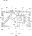
- Fig. 7A shows a perspective left-front view of the intermediate frame 6, and Fig. 7B shows a perspective left-rear view of the intermediate frame 6.
- Fig. 8A shows a front view of the intermediate frame 6,
- Fig. 8B shows a rear view of the intermediate frame 6,
- Fig. 8C shows a left side view of the intermediate frame 6,
- Fig. 8D shows a right side view of the intermediate frame 6,
- Fig. 8E shows a top view of the intermediate frame 6, and
- Fig. 8F shows a bottom view of the intermediate frame 6.
- the intermediate frame 6 includes a main wall 61 with an exterior (rear) surface 61-1 and an interior (front) surface 61-2.
- the main wall 61 has a curved or rounded shape to distribute stress.
- the exterior surface 61-1 has a concave shape, and the interior surface 61-2 has a convex shape.
- the intermediate frame 6 includes an interior space that is defined by wall portions 62.
- the wall portions 62 can include a first upper wall portion 62-1, a second upper wall portion 62-2, a right wall portion 62-3, a left wall portion 62-4, a first lower wall portion 62-5, and a second lower wall portion 62-6.
- One or more of the wall portions 62 can be defined by an edge of the main wall 61.
- one or more bolting portions 67 can be provided along edges of the main wall 61.
- the bolting portions can include a first (upper-right) bolting portion 67-1, a second (upper-middle) bolting portion 67-2, a third (upper-left) bolting portion 67-3, a fourth (lower-right) bolting portion 67-4, a fifth (lower-middle) bolting portion 67-5, and a sixth (lower-left) bolting portion 67-6.
- the intermediate frame 6 can include four bolting portions 67 at each of the four corners of the main wall 61 and two bolting portions at a middle portion of each of an upper edge and a lower edge of the main wall 61.
- Each of the bolting portions 67 can include one or more bolt holes, such that bolts can be inserted through the bolt holes to attach and secure the intermediate frame to battery housing 8.
- the first upper wall portion 62-1 and the second upper wall portion 62-2 are spaced apart from each other by the second (upper-middle) bolting portion 67-2, and the first lower wall portion 62-5 and the second lower wall portion 62-6 are spaced apart from each other by the fifth (lower-middle) bolting portion 67-5.
- At least one of the wall portions 62 is curved.
- each of the first upper wall portion 62-1, the right wall portion 62-3, the left wall portion 62-4, the first lower wall portion 62-5, and the second lower wall portion 62-6 has a curved shape.
- the intermediate frame 6 can have an asymmetrical shape in a plan view.
- the intermediate frame 6 can also include one or more openings 63.
- openings 63 can be provided in the main wall 61 and can be located along one or more of the first upper wall portion 62-1, the second upper wall portion 62-2, the right wall portion 62-3, the left wall portion 62-4, the first lower wall portion 62-5, and the second lower wall portion 62-6.
- the openings 63 can permit the passage of cables, coolant lines, refrigerant lines, oil lines, and the like, as described below with respect to Figs. 10A and 10B .
- the intermediate frame 6 can include a depression 64 on the exterior (rear) surface 61-1.
- the third motor housing portion 12-3 can be fitted to the depression 64, and at least a portion of an outer shape or perimeter of the depression 64 can match or follow a shape of a mounting face of the third motor housing portion 12-3.
- the intermediate frame 6 further includes a motor mount 65, which can be circumscribed by the depression 64.
- the fifth electric motor 22 can be mounted to the intermediate frame 6 at the motor mount 65, as shown in Fig. 10B .
- the motor mount 65 can include a shape that matches or follows a shape of a perimeter of the fifth electric motor 22. At least a portion of the outer shape or perimeter of the depression 64 or the shape of the motor mount 65 can at least partially match or follow a perimeter of a gearing, for example, the fifth gearing 23 or a reduction gear connected to the fifth electric motor 22.
- Figs. 9A and 9B show a perspective left-front view and a top view of the intermediate frame 6 housing components of the vehicle 1.
- the intermediate frame 6 can house a converter 72, a pump 81, a first hydraulic manifold 82, and a second hydraulic manifold 83.
- Each of the converter 72, the pump 81, the first hydraulic manifold 82, and the second hydraulic manifold 83 can be partially or completely located within the space defined by the concave shape of the interior surface 61-1 of the main wall 61.
- the converter 72 can be completely located within the space defined by the concave shape of the interior surface 61-1 of the main wall 61.
- the pump 81 can partially extend beyond each of the first upper wall portion 62-1 and the first lower wall portion 62-5, and the second hydraulic manifold 83 can partially extend beyond the second upper wall portion 62-2.
- the converter 72 can include an electrical converter such as a DC-DC converter, for example, and the DC-DC converter can be a down-converter that converts a battery voltage of one or more batteries included in the battery housing 8 to a lower voltage. At least one surface of the converter 72 can be partially or completely covered by an isolation barrier 73, as shown in Fig. 9A .
- the isolation barrier 73 can be structured to include a flat or textured plate shape.
- the isolation barrier 73 can include an insulating material, for example, an electrically insulating material. Alternatively, or in addition, an isolation barrier can be provided that partially or completely spans between the second upper wall portion 62-2 and the second lower wall portion 62-6.
- the converter 72 can be replaced with another electrical component.
- the pump 81 can be a coolant pump.
- the first hydraulic manifold 82 can be provided to control a distribution of coolant, and the second hydraulic manifold 83 can be provided to control a return of the coolant.
- the first hydraulic manifold 82 and the second hydraulic manifold 83 can each include one or more direction control valves.
- the coolant can be water.
- Figs. 10A and 10B show a perspective left-front view and perspective left-rear view of connections to the components housed in the intermediate frame 6 of the vehicle 1.
- a duct channel 74 and covers 75 and 76 can be connected to or supported by the intermediate frame 6.
- the duct channel 74 can be provided in front of the converter 72, and the duct channel 74 can provide a passage for electrical cables or the like.
- the covers 75 and 76 can also provide protection for electrical cables or the like.
- the duct channel 74 and the covers 75 and 76 guide electrical cables or battery strings.
- the intermediate frame 6 can also be provided with a bracket 79, as shown in Fig. 10A . The bracket 79 can fix and secure the converter 72 within the intermediate frame 6.
- first and second electrical cables 77 and 78 can pass through one of the openings 63 of the intermediate frame 6.
- the first electrical cable 77 can be a positive (+) connection from the converter 72 to a power distribution unit or the like.
- the second electrical cable 78 can be a negate (-) connection from the converter 72 to a power distribution unit or the like.
- Additional electrical cables can be located in and/or pass through the intermediate frame 6.
- one or more of the openings 63 of the intermediate frame 6 can provide a passage for an electrical cable connected between one of the inverters 13 and one of the third electric motor 18, the fourth electric motor 20, the fifth electric motor 22, and the sixth electric motor 24.
- the intermediate frame 6 can house a supply coolant line 84 that supplies coolant from the pump 81 to the first hydraulic manifold 82.
- a plurality of inlet, outlet, return, and/or distribution coolant lines 85 can be connected to one or more of the pump 81, the first hydraulic manifold 82, and the second hydraulic manifold 83.
- One or more of the coolant lines 85 can pass through one or more of the openings 63 of the intermediate frame 6.
- At least one of the coolant lines 85-1 can be provided to supply coolant to the converter 72.
- the coolant can be water.
- one or more further coolant or refrigerant lines 86 can pass through one or more of the openings 63 of the intermediate frame 6 without being directly connected to any of the pump 81, the first hydraulic manifold 82, and the second hydraulic manifold 83.
- the one or more further coolant or refrigerant lines 86 can be connected between a heat exchanger and a component to be cooled.
- the fifth electric motor 22 is mounted to the intermediate frame 6 at the motor mount 65 (shown in Figs. 7B and 8B ).
- the fifth electric motor 22 is connected to the fifth gearing 23, and the fifth gearing 23 can drive an electric vehicle component, for example, a power take-off (PTO) component.
- a plate 90 at least partially cover the fifth electric motor 22.
- the plate 90 can be provided between the fifth electric motor 22 and the fifth gearing 23.
- the plate 90 can define a bearing block or a bearing carrier.
- Figs. 11A and 11B show a perspective left-front view and a front view of a motor cover 66 housed within the intermediate frame 6.
- the motor cover 66 can be located on the interior (front) surface 61-2 of the main wall 61 to cover a portion of the motor mount 65 that is located at the interior (front) surface 61-2 of the main wall 61.
- the motor cover 66 can isolate and protect the converter 72 from the fifth electric motor 22 and from mounting components for the fifth electric motor 22.
- Fig. 12A shows a left side view of the front frame 10
- Fig. 12B shows a perspective left-front view of the front frame 10
- Fig. 12C shows a perspective left-rear view of the front frame 10
- Fig. 12D shows a top view of the front frame 10.
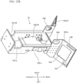
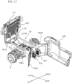
- Fig. 13 shows a perspective left-rear view of the front frame 10 and components provided with the front frame 10.
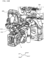
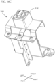
- Figs. 14A and 14B show, respectively, a perspective left-front view and a perspective left-rear view of the front frame 10 and additional components provided with the front frame 10.
- the front frame 10 includes at least a first recessed portion 101, a second recessed portion 102, and a slanted portion 103.
- the first recessed portion 101 includes a first recessed portion 101-R provided on a right side of the front frame 10 and a first recessed portion 101-L provided on a left side of the front frame 10, as shown in Figs. 12B , 12C , and 13 , for example.
- the first recessed portion 101 can receive and support one or more components of the vehicle 1, for example, a cooling structure of the vehicle 1.
- the first recessed portion 101 can receive a fan 111, as shown in Fig. 13 , for example.
- the fan 111 can be mounted to the front frame 10 by one or more posts 112 that attach to the front frame 10 at the first recessed portion 101.
- the second recessed portion 102 includes a second recessed portion 102-R provided on the right side of the front frame 10 and a second recessed portion 102-L provided on the left side of the front frame 10, as shown in Figs. 12B and 12C .
- the second recessed portion 102 can receive one or more components of the vehicle 1.
- the second recessed portion 102 can receive the front axle 3, as shown in Fig. 13 , and the front frame 10 can be supported by the front axle 3 at the second recessed portion 102.
- the slanted portion 103 includes a slanted portion 103-R provided on the right side of the front frame 10 and a slanted portion 103-L provided on the left side of the front frame 10, as shown in Figs. 12B to 12D and 13 .
- the slanted portion 103 is angled away from a main body of the front frame 10. Specifically, the slanted portion 103-R provided on the right side of the front frame 10 extends in a rear-right direction of the vehicle 1, and the slanted portion 103-L provided on the left side of the front frame 10 extends in a rear-left direction of the vehicle 1.
- the slanted portion 103 includes a first opening 104, a second opening 105, and a third opening 106, as shown in Figs. 12A to 12C .
- the slanted portion 103 can also include a fourth opening 107.
- the first opening 104 is preferably larger than each of the second opening 105, the third opening 106, and the fourth opening 107. Accordingly, the first opening 104 can provide an access point to interior components of the vehicle 1.
- the first opening 104 can be covered by a removable plate 108, as shown in Figs. 14A and 14B .
- the second opening 105 can define a portion of a first air channel. As shown in Figs. 14A and 14B , the second opening 105 can communicate with a first air duct 115.
- the first air duct 115 can also be connected to a first opening in the battery housing 8. According to a preferred embodiment of the present invention, the first air duct 115 is mounted to the slanted portion 103, and the first air duct 115 completely covers or circumscribes the first opening 105.
- the third opening 106 can define a portion of a second air channel. As shown in Figs. 14A and 14B , the third opening 106 can communicate with a second air duct 116.
- the second air duct 116 can also be connected to a second opening in the battery housing 8. According to a preferred embodiment of the present invention, the second air duct 116 completely covers or circumscribes the third opening 106.
- the fourth opening 107 can permit the passage of cables, coolant lines, refrigerant lines, oil lines, and the like. According to a preferred embodiment of the present invention, one or more high voltage cables can pass through the fourth opening 107.
- one or more center evaporators 113 can be at least partially housed within the front frame 10.
- the center evaporators 113 can be located directly between the slanted portion 103-R provided on the right side of the front frame 10 and the slanted portion 103-L provided on the left side of the front frame 10.
- the vehicle 1 can include one or more side housings 120.
- the side housing 120 can be located adjacent to, or directly connected with, the slanted portion 103 of the front frame 10.
- Figs. 13 , 14A , and 14B only show a single side housing 120 provided with the slanted portion 103-R on the right side of the front frame 10, a further side housing 120 can similarly be provided with the slanted portion 103-L on the left side of the front frame 10.
- the first air duct 115 can be located adjacent to, or directly connected with, the side housing 120.
- the battery housing 8 at least partially surrounds the front frame 10. More specifically, the third battery housing portion 30, the fourth battery housing portion 32, and the fifth battery housing portion 34 can each be located above the front frame 10, and the fifth battery housing portion 34 can be mounted to an upper portion of the front frame 10.
- Each of the first battery housing portion 26 and the second battery housing portion 28 can be located at a rear portion of the front frame 10, in particular, rearward of the slanted portion 103 of the front frame 10.
- Each of the first battery housing portion 26 and the second battery housing portion 28 can be connected with the slanted portion 103 of the front frame 10.
- An outer edge of each of the first battery housing portion 26 and the second battery housing portion 28 can be aligned with an outer edge of the slanted portion 103 of the front frame 10.
- Fig. 15A shows a perspective left-rear view of a wiring harness 210 of the vehicle 1.
- Figs. 15B and 15C show left and right side views of the wiring harness 210, and
- Fig. 15D shows a top view of the wiring harness 210.
- the vehicle 1 can include a wiring harness 210 to provide electrical power distribution paths to and from each of the inverters 13.
- the wiring harness 210 can include an input 213 and an output 214 for each of the inverters 13.
- the vehicle 1 can include at least one power distribution unit (PDU).
- the vehicle 1 can include a first PDU 220 (e.g., a positive PDU) and a second PDU 230 (e.g., a negative PDU).
- PDU 220 e.g., a positive PDU
- second PDU 230 e.g., a negative PDU
- Each of the first PDU 220 and the second PDU 230 can be connected to each of the inverters 13 by the wiring harness 210.
- the first inverter 13-1 can include an input 213-1 to receive power from the first PDU 220 and/or the second PDU 230.
- the first inverter 13-1 can also include an output 214-1 to output power to the first electric motor 14, which is housed in the left axle housing 3L.
- the second inverter 13-2 can include an input 213-2 to receive power from the first PDU 220 and/or the second PDU 230.
- the second inverter 13-2 can also include an output 214-2 to output power to the second electric motor 16, which is housed in the right axle housing 3R.
- the third inverter 13-3 can include an input 213-3 to receive power from the first PDU 220 and/or the second PDU 230.
- the third inverter 13-3 can also include an output 214-3 to output power to the third electric motor 18, which is housed in the first motor housing portion 12-1.
- the fourth inverter 13-4 can include an input 213-4 to receive power from the first PDU 220 and/or the second PDU 230.
- the fourth inverter 13-4 can also include an output 214-4 to output power to fourth electric motor 20, which is housed in the second motor housing portion 12-2.
- the fifth inverter 13-5 can include an input 213-5 to receive power from the first PDU 220 and/or the second PDU 230.
- the fifth inverter 13-5 can also include an output 214-5 to output power to the fifth electric motor 22, which is housed in the third motor housing portion 12-3.
- the sixth inverter 13-6 can include an input 213-6 to receive power from the first PDU 220 and/or the second PDU 230.
- the sixth inverter 13-6 can also include an output 214-6 to output power to the sixth electric motor 24, which is housed in the fourth motor housing portion 12-4.
- the seventh inverter 13-7 can include an input 213-7 to receive power from the first PDU 220 and/or the second PDU 230.
- the seventh inverter 13-7 can also include an output 214-7 to output power to a cooling structure, for example, the fan 111 shown in Fig. 13 .
- Fig. 16A shows a perspective right-rear view of a battery bracket 310 included in the vehicle 1.
- Fig. 16B is an enlarged view of Fig. 16A , and certain elements have been removed from Fig. 16B for illustrative purposes.
- Fig. 16C shows a perspective right-rear view of the battery bracket 310.
- the battery bracket 310 can be located behind a seat 320 of the vehicle 1.
- a disconnect switch 312 can be provided with the battery bracket 310 to provide easy disconnection of a battery housed by the battery bracket 310.
- the vehicle 1 can include a further battery 315 (shown by dashed lines) that is mounted in the vehicle by the battery bracket 310. That is, battery bracket 310 can hold and secure the further battery 315. Accordingly, the vehicle 1 can include a battery that is not housed by the battery housing 8.
- the further battery 315 can be, for example, a 12 V battery.
- the vehicle 1 can include one or more control levers 330.
- the one or more control levers 330 can include a hydraulic control lever, for example.
- the one or more control levers 330 can be located at a right side of the vehicle 1, that is, at a right side of the seat 320. Accordingly, the one or more control levers 330 can be provided at a same side of the vehicle 1 as the second inverter 13-2, the fourth inverter 13-4, and the fifth inverter 13-5.
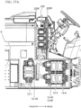
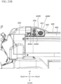
- Fig. 17A shows a left side view of a location of the first PDU 220 according to a preferred embodiment of the present invention.
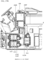
- Fig. 17B shows a right side view of a location of the second PDU 230 according to a preferred embodiment of the present invention.
- a foremost surface 220F of the first PDU 220 can be located rearward of the rearmost surface 13-1R of the first inverter 13-1.
- a rearmost surface 220R of the first PDU 220 can be located forward of a foremost surface 13-3F of the third inverter 13-3 and a foremost surface 13-6F of the sixth inverter 13-6. Accordingly, the first PDU 220 can be located so as to not overlap, in a vertical direction, any of the inverters 13.
- a foremost surface 230F of the second PDU 230 can be located forward of the rearmost surface 13-2R of the second inverter 13-2.
- a rearmost surface 230R of the second PDU 230 can be located forward of the foremost surface 13-4F of the fourth inverter 13-4 and a foremost surface 13-5F of the fifth inverter 13-5.
- the second PDU 230 can be located so at to partially overlap, in a vertical direction, one or more of the inverters 13.
- the first PDU 220 can be a negative PDU
- the second PDU 230 can be a positive PDU.
- Each of the first PDU 220 and the second PDU 230 can be located at a rear portion of the battery housing 8.
- the first PDU 220 can be located at a rear surface of the third battery housing portion 30, and the second PDU 230 can be located at a rear surface of the fourth battery portion 32.
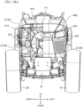
- Fig. 18A shows a front view of the vehicle 1 with an outer cover 400 partially removed.
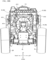
- Figs. 18B and 18C show front and top views of the vehicle 1 with the outer cover 400 completely removed.
- the vehicle 1 can include an outer cover 400.
- the outer cover 400 can define a hood or bonnet of the vehicle 1.
- the vehicle 1 can include cooling components that are mounted at a front surface of the battery housing 8.
- the cooling components can be mounted at a front surface of at least one of the third battery housing portion 30, the fourth battery housing portion 32, and the fifth battery housing portion 34 of the battery housing 8.
- the cooling components can be mounted to the battery housing 8 by one or more mounting brackets 419, as shown in Fig. 18C .
- the cooling components can be mounted to the front frame 10 by the one or more posts 112 that attach to the front frame 10 at the first recessed portion 101, as shown in Fig. 13 .
- the cooling components can include air cooling components and liquid cooling components.
- the air cooling components can include the fan 111, a drier 414, and a condenser 416.
- the liquid cooling components can include a radiator 412, a surge tank 413, and a heat exchanger 415.
- a fan motor 411 can be mounted at a front surface of the fan 111, and the fan motor 411 can receive electric power from the seventh inverter 13-7.
- the fan 111 can be, for example, a radiator/condenser fan.
- the heat exchanger 415 can be, for example, an oil heat exchanger/cooler.
- the fan 111 is located forward of the radiator 412 in the front-rear direction of the vehicle 1.
- the radiator 412 is located forward of the condenser 416 in the front-rear direction of the vehicle 1.
- Figs. 19A and 19B show a left side view of a side opening 402 of the vehicle 1.
- At least one side opening 402 can be provided in the outer cover 400.
- a side opening 402 can be provided at each of a left side and a right side of the outer cover 400.
- the side opening 402 can be covered by the opening cover 403.
- the opening cover 403 is structured to permit air to flow through the side opening 402.
- the opening cover 403 can be, for example, a mesh panel.
- the opening cover 403 is not shown in Fig. 19B for illustrative purposes.
- a foremost edge 402F of the side opening 402 can be located forward of a foremost surface 8F of the battery housing 8.
- the foremost surface 8F of the battery housing can be defined by a foremost surface of the third battery housing portion 30 and/or a foremost surface of the fourth battery housing portion 32.
- the side opening 402 can provide an inlet path for air to the cooling components, such as the fan 111, the radiator 412, and the condenser 416.
- the vehicle 1 can also include one or more front openings provided in a front surface of the outer cover 400.
- the one or more front openings can provide an outlet path for air from the cooling components, such as the fan 111, the radiator 412, and the condenser 416.
- the one or more front openings can be provided only at the front surface of the outer cover 400 or may partially extend onto side surface(s) of the outer cover 400.
- front openings 401 can be provided below headlights 404 of the vehicle 1.
- the third battery housing portion 30 and the fourth battery housing portion 32 are adjacent to each other in a width direction of the vehicle 1, and the fifth battery housing portion 34 is located below the third battery housing portion 30 and the fourth battery housing portion 32. Accordingly, an upper portion of the battery housing 8 (including the third battery housing portion 30 and the fourth battery housing portion 32) can overlap and extend beyond a lower portion of the battery housing 8 (including the fifth battery housing portion 34) in the width direction of the vehicle 1. That is, the battery housing 8 can be provided in a "T" shape with void spaces located at side surfaces of the fifth battery housing portion 34.
- These void spaces can at least partially overlap, in a front view of the vehicle 1, with one or more cooling components such as the fan 111, the radiator 412, and the condenser 416. Furthermore, these void spaces can be located adjacent to the openings 402 in the outer cover 400, and these void spaces can be aligned with further opening(s) provided at a front surface of the outer cover 400.
- Fig. 20A shows a perspective left-rear view of cooling and hydraulic paths of the vehicle 1.
- Fig. 20B shows a perspective right-rear view of cooling and hydraulic paths of the vehicle 1.
- Fig. 20C shows a left side view of the battery housing 8.
- one or more center evaporators 113 can be at least partially housed within the front frame 10.
- one or more forward evaporators 513 can be located at an upper forward portion of the battery housing 8.
- the one or more forward evaporators can be provided at a front surface of the third battery housing portion 30 and/or the fourth battery housing portion 32.
- one or more rear evaporators 523 can be located at a lower rear portion of the battery housing 8.
- the one or more rear evaporators 523 can be provided at a rear surface of the third battery housing portion 30 and/or the fourth battery housing portion 32, and at an upper surface of the first battery housing portion 26 and/or the second battery housing portion 28.
- the rear evaporators 523 can be housed within, or located below, a dashboard of the vehicle 1.
- the intermediate frame 6 can house a pump 81, a first hydraulic manifold 82, and a second hydraulic manifold 83.
- the pump 81 can be a coolant pump.
- the first hydraulic manifold 82 can be provided to control a distribution of coolant
- the second hydraulic manifold 83 can be provided to control a return of the coolant.
- the first hydraulic manifold 82 and the second hydraulic manifold 83 can each include one or more direction control valves.
- the coolant can be water.
- a hydraulic pump 530 and a hydraulic filter 531 can be located at a rear portion of the vehicle 1, that is, to the rear of the battery housing 8 and the intermediate frame 6.
- a hydraulic system of the vehicle 1 can include a hydraulic steering controller 550, a hydraulic brake controller 560, and a hydraulic steering rack 570.
- the hydraulic steering controller 550, the hydraulic brake controller 560, and the hydraulic steering rack 570 can be connected by one or more oil lines to enable to driver of the vehicle 1 to control steering and braking of the vehicle 1.
- one or more oil lines can be connected to a drivetrain gearing of the vehicle 1.
- a compressor 580 can be provided below the cooling components, such as the fan 111, the radiator 412, the surge tank 413, the drier 414, the heat exchanger 415, and the condenser 416.
- the compressor 580 can be housed within the front frame 10.
- the compressor 580 can be, for example, an air compressor.
- a plurality of charge ports 430 can be provided at a rear portion of an outer cover 400 of the vehicle 1.
- the plurality of charge ports 430 can include charge ports 430L provided at a left side of the outer cover 400 and charge ports 430R provided at a right side of the outer cover 400.
- the outer cover 400 can define a hood or bonnet of the vehicle 1.
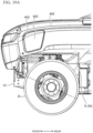
- Fig. 21A shows an enlarged left side view of the charge ports 430L provided at the left side of the outer cover 400.
- a flow of coolant in the vehicle 1 can pass from the pump 81, to the inverters 13 and motor housing portions 12, and then to the radiator 412. That is, coolant output from the pump 81 can be provided as an intake to cool the inverters 13 and electric motors 14, 16, 18, 20, 22, and 24. After cooling the inverters 13 and electric motors 14, 16, 18, 20, 22, and 24, the coolant can then be received by the radiator 412 before returning to the pump 81.
- the charge ports 430L provided at the left side of the outer cover 400 can include a first charge port 431 and a second charge port 432.
- the first charge port 431 can be provided with a port cover 441, which is shown in an open state in Fig. 21A .
- the second charge port 431 can be provided with a port cover 442, which is shown in an open state in Fig. 21A .
- the charge ports 430L provided at the left side of the outer cover 400 can extend above a main upper surface 405 of the outer cover 400 in an up-down direction of the vehicle 1. That is, at least a portion of each of the first charge port 431 and the second charge port 432 can be located higher than the main upper surface 405 of the outer cover 400.
- the outer cover 400 can be provided with a sloped surface 406L that extends over at least the first charge port 431.
- the sloped surface 406L can also extend at least partially over the second charge port 432.
- each of the charge ports 430L can be located forward of the first PDU 220 in a front-rear direction of the vehicle 1.
- each of the charge ports 430L can be located forward of a manual service disconnect plug 221 in the front-rear direction of the vehicle 1.
- the manual service disconnect plug 221 can be located on a left side of the vehicle 1.
- the manual service disconnect plug 221 can disconnect battery connection(s) of the batteries housed within the battery housing 8 of the vehicle 1.
- the manual service disconnect plug 221 can overlap with the first PDU 220 in the front-rear direction of the vehicle 1.
- the vehicle 1 can include a body opening 490 and a step 491 to aid a driver or operating of the vehicle 1 in entering or exiting the vehicle.
- the body opening 490 and the step 491 can be located on a left side of the vehicle 1.
- each of the first charge port 431, the second charge port 432, the manual service disconnect plug 221, the body opening 490, and the step 491 can be located on a left side of the vehicle 1.
- Fig. 21B shows an enlarged right side view of the charge ports 430R provided at the right side of the outer cover 400.
- the charge ports 430R provided at the right side of the outer cover 400 can include a third charge port 433 and a fourth charge port 434.
- the third charge port 433 can be provided with a port cover 443, which is shown in an open state in Fig. 21B .
- the fourth charge port 434 can be provided with a port cover (not shown).
- the charge ports 430R provided at the right side of the outer cover 400 can extend above a main upper surface 405 of the outer cover 400 in an up-down direction of the vehicle 1. That is, at least a portion of each of the third charge port 433 and the fourth charge port 434 can be located higher than the main upper surface 405 of the outer cover 400.
- the outer cover 400 can be provided with a sloped surface 406R that extends over at least the third charge port 433.
- the sloped surface 406L can also extend at least partially over the fourth charge port 434.
- the charge ports 430R can be located below an upper edge 492U of a steering wheel 492 of the vehicle 1.
- the charge ports 430L can also be located below the upper edge 492U of the steering wheel 492.
- the charge ports 430R and 430L are still preferably located lower than the upper edge 492U of the steering wheel 492.
- the charge ports 430R can be located above an upper edge 404U of the headlights 404 of the vehicle 1.
- the charge ports 430L can also be located above the upper edge 404U of the headlights 404.
- the charge ports 430R and 430L are still preferably located lower than the upper edge 492U of the steering wheel 492.
- the hood 400 of the vehicle 1 includes a centerline 400CL located between a front surface 400F and a rear surface 400R of the hood 400 in the front-rear direction of the vehicle 1.
- the charge ports 430R and 430L can be located between the centerline 400CL and the rear surface 400R of the hood in the front-rear direction of the vehicle 1.
- the vehicle 1 is able to avoid impairing the visibility of a driver or operator of the vehicle 1.
- the vehicle 1 is able to provide easy installation operability of a front loader of the vehicle 1.
- each of the charge ports 430R can be located forward of the second PDU 230 in a front-rear direction of the vehicle 1.
- the charge ports 430L provided at a left side of the outer cover 400 can be located symmetrically about a centerline CL of the vehicle 1 with respect to the charge ports 430R provided at a right side of the outer cover 400. That is, the first charge port 431 can be located symmetrically about the centerline CL with respect to the third charge port 433, and the second charge port 432 can be located symmetrically about the centerline CL with respect to the fourth charge port 434.
- a height 433H of the third charge port 433 can be shorter than a height 434H of the fourth charge port 434.
- the fourth charge port 434 can be located closer to the steering wheel 492 and a driver's or operator's seat of the vehicle 1 than the third charge port 433.
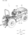
- Figs. 22A and 22B show, respectively, left-front and right-rear perspective views of charging cable connections attached to the vehicle 1.
- Figs. 23A and 23B show, respectively, enlarged left and right side views of the charging cable connections attached to the vehicle 1.
- a first charging cable connection 451 can be connected to the first charge port 431, and a second charging cable connection 452 can be connected to the second charge port 432.
- a third charging cable connection 453 can be connected to the third charge port 433, and a fourth charging cable connection 454 can be connected to the fourth charge port 434.
- Each of the first charging cable connection 451, the second charging cable connection 452, the third charging cable connection 453, and the fourth charging cable connection 454 can be connected to an external power source to charge the batteries housed within the battery housing 8 of the vehicle 1.
- one or more of the first charge port 431, the second charge port 432, and the third charge port 433 can be a DC charge port. Accordingly, each of the first charging cable connection 451, the second charging cable connection 452, the third charging cable connection 453, and the fourth charging cable connection 454 can be connected to an external DC power source. Preferably, one or more of the first charge port 431, the second charge port 432, and the third charge port 433 is compatible with DC fast charging or DC rapid charging. As one example, one or more of the first charge port 431, the second charge port 432, and the third charge port 433 can be compatible with the GB/T charging standard.
- the fourth charge port 434 can be an AC charge port or a combination of an AC charge port and a DC charge port. Accordingly, the fourth charging cable connection 454 can be connected to an external AC power source or an external DC power source. As one example, the fourth charge port 434 can be compatible with the Combined Charging System (CCS) Combo 1 (CCS1) standard.
- CCS Combined Charging System
- CCS1 Combined Charging System
- one or more of the first charge port 431, the second charge port 432, the third charge port 433, and the fourth charge port 434 can function as a discharge port. That is, the vehicle 1 be used to provide electrical power to other devices by discharging electrical power from one or more of the first charge port 431, the second charge port 432, the third charge port 433, and the fourth charge port 434.
Landscapes
- Engineering & Computer Science (AREA)
- Transportation (AREA)
- Mechanical Engineering (AREA)
- Power Engineering (AREA)
- Chemical & Material Sciences (AREA)
- Combustion & Propulsion (AREA)
- Life Sciences & Earth Sciences (AREA)
- Sustainable Development (AREA)
- Sustainable Energy (AREA)
- Arrangement Or Mounting Of Propulsion Units For Vehicles (AREA)
- Body Structure For Vehicles (AREA)
- Electric Propulsion And Braking For Vehicles (AREA)
Abstract
Description
- The present invention is directed to an electric vehicle (EV) such as an electric tractor.
- Electric vehicles (EVs) are becoming more prevalent as the industry moves from internal combustion engines towards fully electrically powered motors running on battery systems.
- Preferred embodiments of the present invention provide an electric work vehicle such as an EV tractor.
- Preferred embodiments of the present invention provide an electric vehicle.
- An electric work vehicle includes a hood, a battery housing including a battery housing portion that houses a plurality of battery modules, and a plurality of charge ports to connect to an external power source to charge the plurality of battery modules. Each of the plurality of charge ports is located at a surface of the hood.
- At least one of the plurality of charge ports can be a DC charge port. At least two of the plurality of charge ports can be DC charge ports. At least three of the plurality of charge ports can be a DC charge ports.
- The electric work vehicle can further include a port cover to cover at least one of the plurality of charge ports. The port cover can be connected to a body of the electric work vehicle by a hinge. The electric work vehicle can further include a latch to secure the port cover in a closed state.
- At least one of the plurality DC charge ports can be located at a rear portion of the hood. At least one of the plurality of charge ports can be located at an upper surface of the hood. At least one of the plurality of charge ports can extend beyond a main upper surface of the hood.
- The hood can include a sloped portion that extends over at least one of the plurality of charge ports. The plurality of charge ports can include a first charge port and a second charge port. The first charge port and the second charge port can be mounted on a same side of the hood in a left-right direction of the electric work vehicle, the second charge port can be located closer to a steering wheel or driver's seat of the electric work vehicle than the first charge port, and the first charge port can be shorter than the second charge port in an up-down direction of the electric work vehicle.
- The plurality of charge ports can include a first charge port mounted on a right side of the hood and a second charge port mounted on a left side of the hood. The first charge port and the second charge port can be located symmetrically about a centerline of the electric work vehicle.
- Each of the plurality of charge ports can be located at a same height in an up-down direction of the electric work vehicle. The electric work vehicle can further include a steering wheel and at least one headlight. Each of the plurality of charge ports can be located below an upper edge of the steering wheel in the up-down direction. Each of the plurality of charge ports can be located above an upper edge of the at least one headlight in the up-down direction. Each of the plurality of charge ports can be located between a rear surface of the hood and a centerline of the hood in a front-rear direction of the electric work vehicle.
- The electric work vehicle can further include a power distribution unit housing that houses a power distribution unit. The plurality of charge ports can be located forward of the power distribution unit housing in a front-rear direction of the electric work vehicle.
- The electric work vehicle can further include a service disconnect plug to disconnect an electrical connection to one or more of the plurality of battery modules. The service disconnect plug can overlap with the power distribution unit in the front-rear direction of the electric work vehicle. The plurality of charge ports can be located forward of the service disconnect plug in the front-rear direction of the electric work vehicle. The service disconnect plug can be located on a same side of the vehicle as at least one of the plurality of charge ports.
- The electric work vehicle can further include an opening structured for an operator of the electric work vehicle to enter or exit the electric work vehicle. At least one of the plurality of charge ports can face a same side of the electric work vehicle as the opening.
- At least one of the plurality of charge ports can be an AC charge port. At least one of the plurality of charge ports can be a combination of an AC charge port and a DC charge port. At least one of the plurality of charge ports can include a main DC electrical connection and an auxiliary DC electrical connection.
- According to preferred embodiments of the present disclosure, it is possible to provide an electric vehicle.
- The above and other features, elements, steps, configurations, characteristics, and advantages of the present invention will become more apparent from the following detailed description of preferred embodiments of the present invention with reference to the attached drawings.
-
-
Fig. 1A shows a perspective left-front view of an electric vehicle according to a preferred embodiment of the present invention. -
Fig. 1B shows a perspective right-front view of an electric vehicle according to a preferred embodiment of the present invention. -
Fig. 1C shows a perspective left-rear view of an electric vehicle according to a preferred embodiment of the present invention. -
Fig. 1D shows a perspective right-rear view of an electric vehicle according to a preferred embodiment of the present invention. -
Fig. 1E shows a front view of an electric vehicle according to a preferred embodiment of the present invention. -
Fig. 1F shows a right side view of an electric vehicle according to a preferred embodiment of the present invention. -
Fig. 1G shows a left side view of an electric vehicle according to a preferred embodiment of the present invention. -
Fig. 1H shows a top view of an electric vehicle according to a preferred embodiment of the present invention. -
Fig. 1I shows a bottom view of an electric vehicle according to a preferred embodiment of the present invention. -
Fig. 1J shows a bottom view of an electric vehicle according to a preferred embodiment of the present invention in which certain elements have been removed for illustrative purposes. -
Fig. 2 shows a rear perspective view of an intermediate frame, a battery housing, a front frame, and a rear frame of an electric vehicle according to a preferred embodiment of the present invention. -
Fig. 3 shows a rear perspective view of a battery housing and a front frame of an electric vehicle according to a preferred embodiment of the present invention. -
Fig. 4 shows a front perspective view of a battery housing according to a preferred embodiment of the present invention. -
Fig. 5A shows a left side view of a battery housing according to a preferred embodiment of the present invention. -
Fig. 5B shows a right side view of a battery housing according to a preferred embodiment of the present invention. -
Fig. 6A shows a left side view of an intermediate frame, a battery housing, a front frame, and a rear frame of an electric vehicle according to a preferred embodiment of the present invention. -
Fig. 6B shows a right side view of an intermediate frame, a battery housing, a front frame, and a rear frame of an electric vehicle according to a preferred embodiment of the present invention. -
Fig. 7A shows a perspective left-front view of an intermediate frame of an electric vehicle according to a preferred embodiment of the present invention. -
Fig. 7B shows a perspective left-rear view of an intermediate frame of an electric vehicle according to a preferred embodiment of the present invention. -
Fig. 8A shows a front view of an intermediate frame of an electric vehicle according to a preferred embodiment of the present invention. -
Fig. 8B shows a rear view of an intermediate frame of an electric vehicle according to a preferred embodiment of the present invention. -
Fig. 8C shows a left side view of an intermediate frame of an electric vehicle according to a preferred embodiment of the present invention. -
Fig. 8D shows a right side view of an intermediate frame of an electric vehicle according to a preferred embodiment of the present invention. -
Fig. 8E shows a top view of an intermediate frame of an electric vehicle according to a preferred embodiment of the present invention. -
Fig. 8F shows a bottom view of an intermediate frame of an electric vehicle according to a preferred embodiment of the present invention. -
Fig. 9A shows a perspective left-front view of an intermediate frame housing components of an electric vehicle according to a preferred embodiment of the present invention. -
Fig. 9B shows a top view of an intermediate frame housing components of an electric vehicle according to a preferred embodiment of the present invention. -
Fig. 10A shows a perspective left-front view of an intermediate frame housing components of an electric vehicle and connections to the components according to a preferred embodiment of the present invention. -
Fig. 10B shows a perspective left-rear view of an intermediate frame housing components of an electric vehicle and connections to the components according to a preferred embodiment of the present invention. -
Fig. 11A shows a perspective left-front view of an intermediate frame of an electric vehicle that includes a motor cover according to a preferred embodiment of the present invention. -
Fig. 11B shows a front view of an intermediate frame of an electric vehicle that includes a motor cover according to a preferred embodiment of the present invention. -
Fig. 12A shows a left side view of a front frame of an electric vehicle according to a preferred embodiment of the present invention. -
Fig. 12B shows a perspective left-front view of a front frame of an electric vehicle according to a preferred embodiment of the present invention. -
Fig. 12C shows a perspective left-rear view of a front frame of an electric vehicle according to a preferred embodiment of the present invention. -
Fig. 12D shows a top view of a front frame of an electric vehicle according to a preferred embodiment of the present invention. -
Fig. 13 shows a perspective left-rear view of a front frame of an electric vehicle and components provided with the front frame according to a preferred embodiment of the present invention. -
Fig. 14A shows a perspective left-front view of a front frame and air ducts of an electric vehicle according to a preferred embodiment of the present invention. -
Fig. 14B shows a perspective left-rear view of a front frame and air ducts of an electric vehicle according to a preferred embodiment of the present invention. -
Fig. 15A shows a perspective left-rear view of a wiring harness of an electric vehicle according to a preferred embodiment of the present invention. -
Fig. 15B shows a left side view of a wiring harness of an electric vehicle according to a preferred embodiment of the present invention. -
Fig. 15C shows a right side view of a wiring harness of an electric vehicle according to a preferred embodiment of the present invention. -
Fig. 15D shows a top view of a wiring harness of an electric vehicle according to a preferred embodiment of the present invention. -
Fig. 16A shows a perspective right-rear view of an electric vehicle including a battery bracket according to a preferred embodiment of the present invention. -
Fig. 16B shows a perspective right-rear view of an electric vehicle including a battery bracket according to a preferred embodiment of the present invention in which certain elements have been removed for illustrative purposes. -
Fig. 16C shows a perspective right-rear view of a battery bracket according to a preferred embodiment of the present invention. -
Fig. 17A shows a left side view of an electric vehicle including a power distribution unit according to a preferred embodiment of the present invention. -
Fig. 17B shows a right side view of an electric vehicle including a power distribution unit according to a preferred embodiment of the present invention. -
Fig. 18A shows a front view of an electric vehicle according to a preferred embodiment of the present invention with an outer cover partially removed. -
Fig. 18B shows a front view of an electric vehicle according to a preferred embodiment of the present invention with an outer cover completely removed. -
Fig. 18C shows a top view of an electric vehicle according to a preferred embodiment of the present invention with an outer cover completely removed. -
Fig. 19A shows a left side view of an electric vehicle including a side opening with a cover according to a preferred embodiment of the present invention. -
Fig. 19B shows a left side view of an electric vehicle including a side opening with a cover removed according to a preferred embodiment of the present invention. -
Fig. 20A shows a perspective left-rear view of cooling and hydraulic paths of an electric vehicle according to a preferred embodiment of the present invention. -
Fig. 20B shows a perspective right-rear view of cooling and hydraulic paths of an electric vehicle according to a preferred embodiment of the present invention. -
Fig. 20C shows a left side view of a battery housing according and cooling and hydraulic paths of an electric vehicle according to a preferred embodiment of the present invention. -
Fig. 21A shows an enlarged left side view of an electric vehicle and charge ports according to a preferred embodiment of the present invention. -
Fig. 21B shows an enlarged right side view of an electric vehicle and charge ports according to a preferred embodiment of the present invention. -
Fig. 22A shows a perspective left-front view of an electric vehicle and charging cable connections according to a preferred embodiment of the present invention. -
Fig. 22B shows a perspective right-rear view of an electric vehicle and charging cable connections according to a preferred embodiment of the present invention. -
Fig. 23A shows an enlarged left side view of an electric vehicle and charging cable connections according to a preferred embodiment of the present invention. -
Fig. 23B shows an enlarged right side view of an electric vehicle and charging cable connections according to a preferred embodiment of the present invention. - Electric vehicles according to preferred embodiments of the present invention may be a tractor or other agricultural vehicle, but any desirable type of electric vehicle is applicable to and usable with preferred embodiments of the present invention.
-
Fig. 1A to 1I show anelectric vehicle 1 according to a preferred embodiment of the present invention.Fig. 1A and1B show perspective views from left and right front ends of thevehicle 1, respectively.Fig. 1C shows an isometric view from a left rear end of thevehicle 1.Fig. 1D shows an isometric view from a right rear end of thevehicle 1.Fig. 1E shows a front view of thevehicle 1.Fig. 1F and1G are side views of thevehicle 1.Fig. 1H and1I are top and bottom views of thevehicle 1, respectively. - In a preferred embodiment of the present invention, as shown, for example, in
Figs. 1A-1H , thevehicle 1 includes aleft front wheel 2L, aright front wheel 2R, a leftrear wheel 4L, and a rightrear wheel 4R. However, a vehicle according to the preferred embodiments of the present invention is not specifically limited to four wheels, and may include any appropriate number of wheels. For example, a vehicle according to the preferred embodiments may include only three wheels by removing one of the aforementioned four wheels, a fifth wheel (e.g., an additional wheel provided in line with a pair of one of the aforementioned four wheels or a wheel provided at a front or rear of the vehicle, etc.), six total wheels by including a pair of center wheels, and the like. In an alternative preferred embodiment, tracks can be used instead of wheels. - In a preferred embodiment of the present invention, the
vehicle 1 includes anintermediate frame 6, abattery housing 8 attached to a front portion of theintermediate frame 6, afront frame 10 attached to thebattery housing 8, and arear frame 12 attached a rear portion of theintermediate frame 6, as shown inFig. 2 , for example. In a preferred embodiment, afront axle 3 connected to theleft front wheel 2L and aright front wheel 2R is connected to and supports thefront frame 10, and arear axle 5 connected to the leftrear wheel 4L and the rightrear wheel 4R is connected to and supported by therear frame 12, as shown inFig. 1I , for example. - In a preferred embodiment of the present invention, the
front axle 3 includes aleft axle housing 3L and aright axle housing 3R, as shown inFig. 1I . Theleft axle housing 3L houses a first electric motor 14 (a left-front-wheel electric motor) that is connected to afirst gearing 15 to drive theleft front wheel 2L, and theright axle housing 3R houses a second electric motor 16 (a right-front-wheel electric motor) that is connected to asecond gearing 17 to drive theright front wheel 2R. The firstelectric motor 14, the secondelectric motor 16, thefirst gearing 15, and thesecond gearing 17 are shown, for example, inFig. 1J in which theleft axle housing 3L and theright axle housing 3R have been removed for illustrative purposes. - In a preferred embodiment of the present invention, the
rear frame 12 includes a first motor housing portion 12-1 to house a third electric motor 18 (a left-rear-wheel electric motor) that is connected to athird gearing 19 to drive the leftrear wheel 4L, and a second motor housing portion 12-2 to house a fourth electric motor 20 (a right-rear-wheel electric motor) that is connected to afourth gearing 21 to drive the rightrear wheel 4R. Preferably, therear frame 12 also includes a third motor housing portion 12-3 to house a fifthelectric motor 22 that is connected to afifth gearing 23 to drive a first electric vehicle component (e.g., a power take-off (PTO)), and a fourth motor housing portion 12-4 to house a sixthelectric motor 24 that is connected to asixth gearing 25 to drive a second electric vehicle component (e.g., a hydraulic system), as shown inFigs. 1J and2 , for example. The thirdelectric motor 18, the fourthelectric motor 20, the fifthelectric motor 22, and the sixthelectric motor 24 are shown, for example, inFig. 1J in which elements including therear frame 12 have been removed for illustrative purposes. In the bottom view ofFig. 1J , the sixthelectric motor 24 overlaps the thirdelectric motor 18. - In a preferred embodiment of the present invention, the
battery housing 8 includes a firstbattery housing portion 26, a secondbattery housing portion 28, a thirdbattery housing portion 30, a fourthbattery housing portion 32, and a fifthbattery housing portion 34, each of which is shown inFig. 3 using dashed lines. In a preferred embodiment, the firstbattery housing portion 26 and the secondbattery housing portion 28 are adjacent to each other in a width direction of the vehicle, and the thirdbattery housing portion 30 and the fourthbattery housing portion 32 are adjacent to each other in a width direction of the vehicle. In a preferred embodiment, a width of each of the firstbattery housing portion 26, the secondbattery housing portion 28, the thirdbattery housing portion 30, the fourthbattery housing portion 32, and the fifthbattery housing portion 34 in a width direction of the vehicle is equal or substantially equal.Figs. 4 ,5A, and 5B show thebattery housing 8 with the battery housing portion covers removed for illustrative purposes. - In a preferred embodiment of the present invention, the first
battery housing portion 26 and the secondbattery housing portion 28 are included in a first battery housing section 8-1 (a rear battery housing section), the thirdbattery housing portion 30 and the fourthbattery housing portion 32 are included in a second battery housing section 8-2 (a forward-upper battery housing section), and the fifthbattery housing portion 34 is included in a third battery housing section 8-3 (a forward-lower battery housing section), as shown inFig. 3 , for example. In a preferred embodiment, a width of the first battery housing section 8-1 is equal or substantially equal to a width of the second battery housing section 8-2, and a width of the third battery housing section 8-3 is less than a width of the first battery housing section 8-1 and a width of the second battery housing section 8-2. Preferably, a rear surface of the third battery housing section 8-3 is spaced away from a front surface of the first battery housing section 8-1. In a preferred embodiment, a rear surface of the second battery housing section 8-2 intersects a middle portion of the first battery housing section 8-1 in a front-rear direction of the electric vehicle in a top view and a side view. - As shown in
Figs. 4 ,5A, and 5B , each of the firstbattery housing portion 26, the secondbattery housing portion 28, the thirdbattery housing portion 30, the fourthbattery housing portion 32, and the fifthbattery housing portion 34 includes a plurality of battery housing module compartments, which are each to receive a battery module. In a preferred embodiment, each of the thirdbattery housing portion 30 and the fourthbattery housing portion 32 includes more battery housing module compartments than each of the firstbattery housing portion 26 and the secondbattery housing portion 28. Preferably, the fifthbattery housing portion 34 includes less battery housing module compartments than each of the firstbattery housing portion 26 and the secondbattery housing portion 28. -
Figs. 6A and6B show, respectively, left and right side views of theintermediate frame 6, thebattery housing 8, thefront frame 10, and therear frame 12 shown inFig. 2 , for example. A front portion of theintermediate frame 6 is attached to a rear portion of thebattery housing 8, and a rear portion of theintermediate frame 6 is attached to a front portion of therear frame 12. As shown inFigs. 6A and6B , theintermediate frame 6 is located between thebattery housing 8 and therear axle 5 in the front-rear direction of thevehicle 1. A chassis of thevehicle 1 can include theintermediate frame 6 and thefront frame 10. - As described above, the
rear frame 12 can include the first motor housing portion 12-1 to house the thirdelectric motor 18, the second motor housing portion 12-2 to house the fourthelectric motor 20, the third motor housing portion 12-3 to house the fifthelectric motor 22, and the fourth motor housing portion 12-4 to house the sixthelectric motor 24. In a preferred embodiment of the present invention, as shown, for example, inFigs. 6A and6B , the first motor housing portion 12-1, the second motor housing portion 12-2, the third motor housing portion 12-3, and the fourth motor housing portion 12-4 are preferably located in a rearward direction of theintermediate frame 6. Accordingly, each of the thirdelectric motor 18, the fourthelectric motor 20, the fifthelectric motor 22, and the sixthelectric motor 24 are preferably located rearwardly of theintermediate frame 6 in a front-rear direction of thevehicle 1. - In a preferred embodiment of the present invention, as shown, for example, in
Figs. 6A and6B , one or more inverters 13 are connected to, attached on, or supported by thebattery housing 8. For example, the one or more inverters 13 can include a first inverter 13-1, a second inverter 13-2, a third inverter 13-3, a fourth inverter 13-4, a fifth inverter 13-5, a sixth inverter 13-6, and a seventh inverter 13-7. Preferably, as shown inFig. 6A , the first inverter 13-1, the third inverter 13-3, the sixth inverter 13-6, and the seventh inverter 13-7 are located on a left side of thebattery housing 8. Preferably, as shown inFig. 6B , the second inverter 13-2, the fourth inverter 13-4, and the fifth inverter 13-5 are located on a right side of thebattery housing 8. More specifically, as shown inFigs. 6A and6B , the seventh inverter 13-7 can be attached to a left side cover of the fifthbattery housing portion 34, each of the first inverter 13-1, the third inverter 13-3, and the sixth inverter 13-6 can be attached to a left side cover of the secondbattery housing portion 28, and each of the second inverter 13-2, the fourth inverter 13-4, and the fifth inverter 13-5 can be attached to a right side cover of the firstbattery housing portion 26. However, the total number of the inverters 13 is not limited, and the inverters 13 may be provided at other locations within thevehicle 1. - In preferred embodiment of the present invention, the first inverter 13-1 can provide electric power to the first
electric motor 14, the second inverter 13-2 can provide electric power to the secondelectric motor 16, the third inverter 13-3 can provide electric power to the thirdelectric motor 18, the fourth inverter 13-4 can provide electric power to the fourthelectric motor 20, the fifth inverter 13-5 can provide electric power to the fifthelectric motor 22, and the sixth inverter 13-6 can provide electric power to the sixthelectric motor 24. The seventh inverter 13-7 can provide electric power to other components of theelectric vehicle 1, for example, a cooling structure such as a 111 shown inFig. 13 and discussed in further detail herein. - In a preferred embodiment of the present invention, the first inverter 13-1 and the second inverter 13-2 can be located symmetrically about a centerline of the
vehicle 1. In a preferred embodiment of the present invention, the third inverter 13-3 and the fourth inverter 13-4 can be located symmetrically about the centerline of thevehicle 1. In a preferred embodiment of the present invention, the fifth inverter 13-5 and the sixth inverter 13-6 can be located symmetrically about the centerline of thevehicle 1. - In a preferred embodiment of the present invention, the first motor housing portion 12-1 and the second motor housing portion 12-2 can be located symmetrically about a centerline of the
vehicle 1. Accordingly, the thirdelectric motor 18 and the fourthelectric motor 20 can be located symmetrically about a centerline of thevehicle 1. -
Fig. 7A shows a perspective left-front view of theintermediate frame 6, andFig. 7B shows a perspective left-rear view of theintermediate frame 6.Fig. 8A shows a front view of theintermediate frame 6,Fig. 8B shows a rear view of theintermediate frame 6,Fig. 8C shows a left side view of theintermediate frame 6,Fig. 8D shows a right side view of theintermediate frame 6,Fig. 8E shows a top view of theintermediate frame 6, andFig. 8F shows a bottom view of theintermediate frame 6. - In a preferred embodiment of the present invention, as shown, for example, in
Figs. 7A-8F , theintermediate frame 6 includes amain wall 61 with an exterior (rear) surface 61-1 and an interior (front) surface 61-2. Themain wall 61 has a curved or rounded shape to distribute stress. The exterior surface 61-1 has a concave shape, and the interior surface 61-2 has a convex shape. Theintermediate frame 6 includes an interior space that is defined by wall portions 62. The wall portions 62 can include a first upper wall portion 62-1, a second upper wall portion 62-2, a right wall portion 62-3, a left wall portion 62-4, a first lower wall portion 62-5, and a second lower wall portion 62-6. One or more of the wall portions 62 can be defined by an edge of themain wall 61. - According to a preferred embodiment of the present invention, for example, as shown in
Figs. 7A ,7B ,8A , and8B , one or more bolting portions 67 can be provided along edges of themain wall 61. The bolting portions can include a first (upper-right) bolting portion 67-1, a second (upper-middle) bolting portion 67-2, a third (upper-left) bolting portion 67-3, a fourth (lower-right) bolting portion 67-4, a fifth (lower-middle) bolting portion 67-5, and a sixth (lower-left) bolting portion 67-6. That is, theintermediate frame 6 can include four bolting portions 67 at each of the four corners of themain wall 61 and two bolting portions at a middle portion of each of an upper edge and a lower edge of themain wall 61. Each of the bolting portions 67 can include one or more bolt holes, such that bolts can be inserted through the bolt holes to attach and secure the intermediate frame tobattery housing 8. - According to a preferred embodiment of the present invention, for example, as shown in
Figs. 7A and8A , the first upper wall portion 62-1 and the second upper wall portion 62-2 are spaced apart from each other by the second (upper-middle) bolting portion 67-2, and the first lower wall portion 62-5 and the second lower wall portion 62-6 are spaced apart from each other by the fifth (lower-middle) bolting portion 67-5. - According to a preferred embodiment of the present invention, at least one of the wall portions 62 is curved. For example, as shown in
Figs. 7A ,8A , and8C-8F , each of the first upper wall portion 62-1, the right wall portion 62-3, the left wall portion 62-4, the first lower wall portion 62-5, and the second lower wall portion 62-6 has a curved shape. According to the shapes of thewalls 61 and the wall portions 62, theintermediate frame 6 can have an asymmetrical shape in a plan view. - According to a preferred embodiment of the present invention, the
intermediate frame 6 can also include one ormore openings 63. As shown inFigs. 7A and7B ,openings 63 can be provided in themain wall 61 and can be located along one or more of the first upper wall portion 62-1, the second upper wall portion 62-2, the right wall portion 62-3, the left wall portion 62-4, the first lower wall portion 62-5, and the second lower wall portion 62-6. Theopenings 63 can permit the passage of cables, coolant lines, refrigerant lines, oil lines, and the like, as described below with respect toFigs. 10A and10B . - In a preferred embodiment of the present invention, as shown, for example, in
Figs. 7B and8B , theintermediate frame 6 can include adepression 64 on the exterior (rear) surface 61-1. The third motor housing portion 12-3 can be fitted to thedepression 64, and at least a portion of an outer shape or perimeter of thedepression 64 can match or follow a shape of a mounting face of the third motor housing portion 12-3. Theintermediate frame 6 further includes amotor mount 65, which can be circumscribed by thedepression 64. The fifthelectric motor 22 can be mounted to theintermediate frame 6 at themotor mount 65, as shown inFig. 10B . Themotor mount 65 can include a shape that matches or follows a shape of a perimeter of the fifthelectric motor 22. At least a portion of the outer shape or perimeter of thedepression 64 or the shape of themotor mount 65 can at least partially match or follow a perimeter of a gearing, for example, thefifth gearing 23 or a reduction gear connected to the fifthelectric motor 22. -
Figs. 9A and9B show a perspective left-front view and a top view of theintermediate frame 6 housing components of thevehicle 1. - In a preferred embodiment of the present invention, as shown, for example, in
Fig. 9A , theintermediate frame 6 can house aconverter 72, apump 81, a firsthydraulic manifold 82, and a secondhydraulic manifold 83. Each of theconverter 72, thepump 81, the firsthydraulic manifold 82, and the secondhydraulic manifold 83 can be partially or completely located within the space defined by the concave shape of the interior surface 61-1 of themain wall 61. For example, as shown inFig. 9B , theconverter 72 can be completely located within the space defined by the concave shape of the interior surface 61-1 of themain wall 61. However, thepump 81 can partially extend beyond each of the first upper wall portion 62-1 and the first lower wall portion 62-5, and the secondhydraulic manifold 83 can partially extend beyond the second upper wall portion 62-2. - According to a preferred embodiment of the present invention, the
converter 72 can include an electrical converter such as a DC-DC converter, for example, and the DC-DC converter can be a down-converter that converts a battery voltage of one or more batteries included in thebattery housing 8 to a lower voltage. At least one surface of theconverter 72 can be partially or completely covered by anisolation barrier 73, as shown inFig. 9A . Theisolation barrier 73 can be structured to include a flat or textured plate shape. Theisolation barrier 73 can include an insulating material, for example, an electrically insulating material. Alternatively, or in addition, an isolation barrier can be provided that partially or completely spans between the second upper wall portion 62-2 and the second lower wall portion 62-6. In another preferred embodiment of the present invention, theconverter 72 can be replaced with another electrical component. - According to a preferred embodiment of the present invention, the
pump 81 can be a coolant pump. The firsthydraulic manifold 82 can be provided to control a distribution of coolant, and the secondhydraulic manifold 83 can be provided to control a return of the coolant. The firsthydraulic manifold 82 and the secondhydraulic manifold 83 can each include one or more direction control valves. As one example, the coolant can be water. -
Figs. 10A and10B show a perspective left-front view and perspective left-rear view of connections to the components housed in theintermediate frame 6 of thevehicle 1. - In a preferred embodiment of the present invention, as shown, for example, in
Fig. 10A , aduct channel 74 and covers 75 and 76 can be connected to or supported by theintermediate frame 6. Theduct channel 74 can be provided in front of theconverter 72, and theduct channel 74 can provide a passage for electrical cables or the like. Thecovers duct channel 74 and thecovers intermediate frame 6 can also be provided with abracket 79, as shown inFig. 10A . Thebracket 79 can fix and secure theconverter 72 within theintermediate frame 6. - In a preferred embodiment of the present invention, as shown, for example, in
Figs. 10A and10B , first and secondelectrical cables openings 63 of theintermediate frame 6. The firstelectrical cable 77 can be a positive (+) connection from theconverter 72 to a power distribution unit or the like. The secondelectrical cable 78 can be a negate (-) connection from theconverter 72 to a power distribution unit or the like. Additional electrical cables can be located in and/or pass through theintermediate frame 6. For example, one or more of theopenings 63 of theintermediate frame 6 can provide a passage for an electrical cable connected between one of the inverters 13 and one of the thirdelectric motor 18, the fourthelectric motor 20, the fifthelectric motor 22, and the sixthelectric motor 24. - In a preferred embodiment of the present invention, as shown, for example, in
Fig. 10A , theintermediate frame 6 can house asupply coolant line 84 that supplies coolant from thepump 81 to the firsthydraulic manifold 82. A plurality of inlet, outlet, return, and/ordistribution coolant lines 85 can be connected to one or more of thepump 81, the firsthydraulic manifold 82, and the secondhydraulic manifold 83. One or more of thecoolant lines 85 can pass through one or more of theopenings 63 of theintermediate frame 6. At least one of the coolant lines 85-1 can be provided to supply coolant to theconverter 72. As one example, the coolant can be water. - According to a preferred embodiment of the present invention, one or more further coolant or
refrigerant lines 86 can pass through one or more of theopenings 63 of theintermediate frame 6 without being directly connected to any of thepump 81, the firsthydraulic manifold 82, and the secondhydraulic manifold 83. For example, the one or more further coolant orrefrigerant lines 86 can be connected between a heat exchanger and a component to be cooled. - In a preferred embodiment of the present invention, as shown, for example, in
Fig. 10B , the fifthelectric motor 22 is mounted to theintermediate frame 6 at the motor mount 65 (shown inFigs. 7B and8B ). The fifthelectric motor 22 is connected to thefifth gearing 23, and thefifth gearing 23 can drive an electric vehicle component, for example, a power take-off (PTO) component. As shown inFig. 10B , aplate 90 at least partially cover the fifthelectric motor 22. Theplate 90 can be provided between the fifthelectric motor 22 and thefifth gearing 23. Theplate 90 can define a bearing block or a bearing carrier. -
Figs. 11A and11B show a perspective left-front view and a front view of amotor cover 66 housed within theintermediate frame 6. - In a preferred embodiment of the present invention, as shown, for example, in
Figs. 11A and11B , themotor cover 66 can be located on the interior (front) surface 61-2 of themain wall 61 to cover a portion of themotor mount 65 that is located at the interior (front) surface 61-2 of themain wall 61. Themotor cover 66 can isolate and protect theconverter 72 from the fifthelectric motor 22 and from mounting components for the fifthelectric motor 22. -
Fig. 12A shows a left side view of thefront frame 10,Fig. 12B shows a perspective left-front view of thefront frame 10,Fig. 12C shows a perspective left-rear view of thefront frame 10, andFig. 12D shows a top view of thefront frame 10.Fig. 13 shows a perspective left-rear view of thefront frame 10 and components provided with thefront frame 10.Figs. 14A and14B show, respectively, a perspective left-front view and a perspective left-rear view of thefront frame 10 and additional components provided with thefront frame 10. - In a preferred embodiment of the present invention, as shown, for example, in
Figs. 12A to 12C , thefront frame 10 includes at least a first recessedportion 101, a second recessedportion 102, and aslanted portion 103. - The first recessed
portion 101 includes a first recessed portion 101-R provided on a right side of thefront frame 10 and a first recessed portion 101-L provided on a left side of thefront frame 10, as shown inFigs. 12B ,12C , and13 , for example. The first recessedportion 101 can receive and support one or more components of thevehicle 1, for example, a cooling structure of thevehicle 1. According to a preferred embodiment of the present invention, the first recessedportion 101 can receive afan 111, as shown inFig. 13 , for example. Thefan 111 can be mounted to thefront frame 10 by one ormore posts 112 that attach to thefront frame 10 at the first recessedportion 101. - The second recessed
portion 102 includes a second recessed portion 102-R provided on the right side of thefront frame 10 and a second recessed portion 102-L provided on the left side of thefront frame 10, as shown inFigs. 12B and12C . The second recessedportion 102 can receive one or more components of thevehicle 1. According to a preferred embodiment of the present invention, the second recessedportion 102 can receive thefront axle 3, as shown inFig. 13 , and thefront frame 10 can be supported by thefront axle 3 at the second recessedportion 102. - The slanted
portion 103 includes a slanted portion 103-R provided on the right side of thefront frame 10 and a slanted portion 103-L provided on the left side of thefront frame 10, as shown inFigs. 12B to 12D and13 . The slantedportion 103 is angled away from a main body of thefront frame 10. Specifically, the slanted portion 103-R provided on the right side of thefront frame 10 extends in a rear-right direction of thevehicle 1, and the slanted portion 103-L provided on the left side of thefront frame 10 extends in a rear-left direction of thevehicle 1. - The slanted
portion 103 includes afirst opening 104, asecond opening 105, and athird opening 106, as shown inFigs. 12A to 12C . The slantedportion 103 can also include afourth opening 107. - The
first opening 104 is preferably larger than each of thesecond opening 105, thethird opening 106, and thefourth opening 107. Accordingly, thefirst opening 104 can provide an access point to interior components of thevehicle 1. Thefirst opening 104 can be covered by aremovable plate 108, as shown inFigs. 14A and14B . - The
second opening 105 can define a portion of a first air channel. As shown inFigs. 14A and14B , thesecond opening 105 can communicate with afirst air duct 115. Thefirst air duct 115 can also be connected to a first opening in thebattery housing 8. According to a preferred embodiment of the present invention, thefirst air duct 115 is mounted to the slantedportion 103, and thefirst air duct 115 completely covers or circumscribes thefirst opening 105. - The
third opening 106 can define a portion of a second air channel. As shown inFigs. 14A and14B , thethird opening 106 can communicate with asecond air duct 116. Thesecond air duct 116 can also be connected to a second opening in thebattery housing 8. According to a preferred embodiment of the present invention, thesecond air duct 116 completely covers or circumscribes thethird opening 106. - The
fourth opening 107 can permit the passage of cables, coolant lines, refrigerant lines, oil lines, and the like. According to a preferred embodiment of the present invention, one or more high voltage cables can pass through thefourth opening 107. - In a preferred embodiment of the present invention, as shown, for example, in
Figs. 13 ,14A , and14B , one ormore center evaporators 113 can be at least partially housed within thefront frame 10. The center evaporators 113 can be located directly between the slanted portion 103-R provided on the right side of thefront frame 10 and the slanted portion 103-L provided on the left side of thefront frame 10. - In a preferred embodiment of the present invention, as shown, for example, in
Figs. 1A to 1D ,1F ,1G ,13 ,14A , and14B , thevehicle 1 can include one or more side housings 120. As shown inFigs. 13 ,14A , and14B , theside housing 120 can be located adjacent to, or directly connected with, the slantedportion 103 of thefront frame 10. AlthoughFigs. 13 ,14A , and14B only show asingle side housing 120 provided with the slanted portion 103-R on the right side of thefront frame 10, afurther side housing 120 can similarly be provided with the slanted portion 103-L on the left side of thefront frame 10. According to a preferred embodiment of the present invention as shown, for example, inFigs. 14A and14B , thefirst air duct 115 can be located adjacent to, or directly connected with, theside housing 120. - In a preferred embodiment of the present invention, as shown, for example, in
Figs. 4 ,5A ,5B ,6A and6B , thebattery housing 8 at least partially surrounds thefront frame 10. More specifically, the thirdbattery housing portion 30, the fourthbattery housing portion 32, and the fifthbattery housing portion 34 can each be located above thefront frame 10, and the fifthbattery housing portion 34 can be mounted to an upper portion of thefront frame 10. Each of the firstbattery housing portion 26 and the secondbattery housing portion 28 can be located at a rear portion of thefront frame 10, in particular, rearward of the slantedportion 103 of thefront frame 10. Each of the firstbattery housing portion 26 and the secondbattery housing portion 28 can be connected with the slantedportion 103 of thefront frame 10. An outer edge of each of the firstbattery housing portion 26 and the secondbattery housing portion 28 can be aligned with an outer edge of the slantedportion 103 of thefront frame 10. -
Fig. 15A shows a perspective left-rear view of awiring harness 210 of thevehicle 1.Figs. 15B and15C show left and right side views of thewiring harness 210, andFig. 15D shows a top view of thewiring harness 210. - According to a preferred embodiment of the present invention, as shown, for example, in
Figs. 15A to 15D , thevehicle 1 can include awiring harness 210 to provide electrical power distribution paths to and from each of the inverters 13. Thewiring harness 210 can include an input 213 and an output 214 for each of the inverters 13. - According to a preferred embodiment of the present invention, as shown, for example, in
Figs. 15A to 15D , thevehicle 1 can include at least one power distribution unit (PDU). According to a preferred embodiment of the present invention, thevehicle 1 can include a first PDU 220 (e.g., a positive PDU) and a second PDU 230 (e.g., a negative PDU). Each of thefirst PDU 220 and thesecond PDU 230 can be connected to each of the inverters 13 by thewiring harness 210. - According to a preferred embodiment of the present invention, as shown, for example, in
Fig. 15B , the first inverter 13-1 can include an input 213-1 to receive power from thefirst PDU 220 and/or thesecond PDU 230. The first inverter 13-1 can also include an output 214-1 to output power to the firstelectric motor 14, which is housed in theleft axle housing 3L. - According to a preferred embodiment of the present invention, as shown, for example, in
Fig. 15C , the second inverter 13-2 can include an input 213-2 to receive power from thefirst PDU 220 and/or thesecond PDU 230. The second inverter 13-2 can also include an output 214-2 to output power to the secondelectric motor 16, which is housed in theright axle housing 3R. - According to a preferred embodiment of the present invention, as shown, for example, in
Fig. 15B , the third inverter 13-3 can include an input 213-3 to receive power from thefirst PDU 220 and/or thesecond PDU 230. The third inverter 13-3 can also include an output 214-3 to output power to the thirdelectric motor 18, which is housed in the first motor housing portion 12-1. - According to a preferred embodiment of the present invention, as shown, for example, in
Fig. 15C , the fourth inverter 13-4 can include an input 213-4 to receive power from thefirst PDU 220 and/or thesecond PDU 230. The fourth inverter 13-4 can also include an output 214-4 to output power to fourthelectric motor 20, which is housed in the second motor housing portion 12-2. - According to a preferred embodiment of the present invention, as shown, for example, in
Fig. 15C , the fifth inverter 13-5 can include an input 213-5 to receive power from thefirst PDU 220 and/or thesecond PDU 230. The fifth inverter 13-5 can also include an output 214-5 to output power to the fifthelectric motor 22, which is housed in the third motor housing portion 12-3. - According to a preferred embodiment of the present invention, as shown, for example, in
Fig. 15B , the sixth inverter 13-6 can include an input 213-6 to receive power from thefirst PDU 220 and/or thesecond PDU 230. The sixth inverter 13-6 can also include an output 214-6 to output power to the sixthelectric motor 24, which is housed in the fourth motor housing portion 12-4. - According to a preferred embodiment of the present invention, as shown, for example, in
Fig. 15B , the seventh inverter 13-7 can include an input 213-7 to receive power from thefirst PDU 220 and/or thesecond PDU 230. The seventh inverter 13-7 can also include an output 214-7 to output power to a cooling structure, for example, thefan 111 shown inFig. 13 . -
Fig. 16A shows a perspective right-rear view of abattery bracket 310 included in thevehicle 1.Fig. 16B is an enlarged view ofFig. 16A , and certain elements have been removed fromFig. 16B for illustrative purposes.Fig. 16C shows a perspective right-rear view of thebattery bracket 310. - According to a preferred embodiment of the present invention, as shown, for example, in
Figs. 16A and16B , thebattery bracket 310 can be located behind aseat 320 of thevehicle 1. According to a preferred embodiment of the present invention, as shown, for example, inFig. 16C , adisconnect switch 312 can be provided with thebattery bracket 310 to provide easy disconnection of a battery housed by thebattery bracket 310. - According to a preferred embodiment of the present invention, as shown, for example, in
Fig. 16B , thevehicle 1 can include a further battery 315 (shown by dashed lines) that is mounted in the vehicle by thebattery bracket 310. That is,battery bracket 310 can hold and secure thefurther battery 315. Accordingly, thevehicle 1 can include a battery that is not housed by thebattery housing 8. Thefurther battery 315 can be, for example, a 12 V battery. - According to a preferred embodiment of the present invention, as shown, for example, in
Figs. 16A and16B , thevehicle 1 can include one or more control levers 330. The one ormore control levers 330 can include a hydraulic control lever, for example. As shown inFigs. 16A and16B , the one ormore control levers 330 can be located at a right side of thevehicle 1, that is, at a right side of theseat 320. Accordingly, the one ormore control levers 330 can be provided at a same side of thevehicle 1 as the second inverter 13-2, the fourth inverter 13-4, and the fifth inverter 13-5. -
Fig. 17A shows a left side view of a location of thefirst PDU 220 according to a preferred embodiment of the present invention.Fig. 17B shows a right side view of a location of thesecond PDU 230 according to a preferred embodiment of the present invention. - According to a preferred embodiment of the present invention, as shown, for example, in
Fig. 17A , aforemost surface 220F of thefirst PDU 220 can be located rearward of the rearmost surface 13-1R of the first inverter 13-1. In addition, arearmost surface 220R of thefirst PDU 220 can be located forward of a foremost surface 13-3F of the third inverter 13-3 and a foremost surface 13-6F of the sixth inverter 13-6. Accordingly, thefirst PDU 220 can be located so as to not overlap, in a vertical direction, any of the inverters 13. - According to a preferred embodiment of the present invention, as shown, for example, in
Fig. 17B , aforemost surface 230F of thesecond PDU 230 can be located forward of the rearmost surface 13-2R of the second inverter 13-2. In addition, arearmost surface 230R of thesecond PDU 230 can be located forward of the foremost surface 13-4F of the fourth inverter 13-4 and a foremost surface 13-5F of the fifth inverter 13-5. Accordingly, thesecond PDU 230 can be located so at to partially overlap, in a vertical direction, one or more of the inverters 13. - According to a preferred embodiment of the present invention, the
first PDU 220 can be a negative PDU, and thesecond PDU 230 can be a positive PDU. Each of thefirst PDU 220 and thesecond PDU 230 can be located at a rear portion of thebattery housing 8. In particular, thefirst PDU 220 can be located at a rear surface of the thirdbattery housing portion 30, and thesecond PDU 230 can be located at a rear surface of thefourth battery portion 32. -
Fig. 18A shows a front view of thevehicle 1 with anouter cover 400 partially removed.Figs. 18B and18C show front and top views of thevehicle 1 with theouter cover 400 completely removed. - According to a preferred embodiment of the present invention, as shown, for example, in
Fig. 18A , thevehicle 1 can include anouter cover 400. Theouter cover 400 can define a hood or bonnet of thevehicle 1. - According to a preferred embodiment of the present invention, as shown, for example, in
Figs. 18A to 18C , thevehicle 1 can include cooling components that are mounted at a front surface of thebattery housing 8. In particular, the cooling components can be mounted at a front surface of at least one of the thirdbattery housing portion 30, the fourthbattery housing portion 32, and the fifthbattery housing portion 34 of thebattery housing 8. The cooling components can be mounted to thebattery housing 8 by one or more mountingbrackets 419, as shown inFig. 18C . Alternatively or in addition, the cooling components can be mounted to thefront frame 10 by the one ormore posts 112 that attach to thefront frame 10 at the first recessedportion 101, as shown inFig. 13 . - The cooling components can include air cooling components and liquid cooling components. The air cooling components can include the
fan 111, a drier 414, and acondenser 416. The liquid cooling components can include aradiator 412, asurge tank 413, and aheat exchanger 415. As shown inFig. 18C , afan motor 411 can be mounted at a front surface of thefan 111, and thefan motor 411 can receive electric power from the seventh inverter 13-7. Thefan 111 can be, for example, a radiator/condenser fan. Theheat exchanger 415 can be, for example, an oil heat exchanger/cooler. - According to a preferred embodiment of the present invention, as shown, for example, in
Fig. 18C , thefan 111 is located forward of theradiator 412 in the front-rear direction of thevehicle 1. According to a preferred embodiment of the present invention, as shown, for example, inFig. 18C , theradiator 412 is located forward of thecondenser 416 in the front-rear direction of thevehicle 1. -
Figs. 19A and19B show a left side view of aside opening 402 of thevehicle 1. - According to a preferred embodiment of the present invention, for example, as shown in
Figs. 19A and19B , at least oneside opening 402 can be provided in theouter cover 400. For example, aside opening 402 can be provided at each of a left side and a right side of theouter cover 400. - According to a preferred embodiment of the present invention, for example, as shown in
Fig. 19A , theside opening 402 can be covered by theopening cover 403. According to a preferred embodiment of the present invention, theopening cover 403 is structured to permit air to flow through theside opening 402. Theopening cover 403 can be, for example, a mesh panel. - The
opening cover 403 is not shown inFig. 19B for illustrative purposes. According to a preferred embodiment of the present invention, for example, as shown inFig. 19B , aforemost edge 402F of theside opening 402 can be located forward of aforemost surface 8F of thebattery housing 8. Theforemost surface 8F of the battery housing can be defined by a foremost surface of the thirdbattery housing portion 30 and/or a foremost surface of the fourthbattery housing portion 32. - According to a preferred embodiment of the present invention, the
side opening 402 can provide an inlet path for air to the cooling components, such as thefan 111, theradiator 412, and thecondenser 416. - According to a preferred embodiment of the present invention, the
vehicle 1 can also include one or more front openings provided in a front surface of theouter cover 400. The one or more front openings can provide an outlet path for air from the cooling components, such as thefan 111, theradiator 412, and thecondenser 416. The one or more front openings can be provided only at the front surface of theouter cover 400 or may partially extend onto side surface(s) of theouter cover 400. According to a preferred embodiment of the present invention, for example, as shown inFigs. 1E and18A ,front openings 401 can be provided belowheadlights 404 of thevehicle 1. - According to a preferred embodiment of the present invention, as shown, for example, in
Figs. 2 to 4 , the thirdbattery housing portion 30 and the fourthbattery housing portion 32 are adjacent to each other in a width direction of thevehicle 1, and the fifthbattery housing portion 34 is located below the thirdbattery housing portion 30 and the fourthbattery housing portion 32. Accordingly, an upper portion of the battery housing 8 (including the thirdbattery housing portion 30 and the fourth battery housing portion 32) can overlap and extend beyond a lower portion of the battery housing 8 (including the fifth battery housing portion 34) in the width direction of thevehicle 1. That is, thebattery housing 8 can be provided in a "T" shape with void spaces located at side surfaces of the fifthbattery housing portion 34. These void spaces can at least partially overlap, in a front view of thevehicle 1, with one or more cooling components such as thefan 111, theradiator 412, and thecondenser 416. Furthermore, these void spaces can be located adjacent to theopenings 402 in theouter cover 400, and these void spaces can be aligned with further opening(s) provided at a front surface of theouter cover 400. -
Fig. 20A shows a perspective left-rear view of cooling and hydraulic paths of thevehicle 1.Fig. 20B shows a perspective right-rear view of cooling and hydraulic paths of thevehicle 1.Fig. 20C shows a left side view of thebattery housing 8. - In a preferred embodiment of the present invention, as shown, for example, in
Figs. 13 ,14A ,14B , and20A to20C one ormore center evaporators 113 can be at least partially housed within thefront frame 10. - In a preferred embodiment of the present invention, as shown, for example, in
Figs. 20A to 20C , one or moreforward evaporators 513 can be located at an upper forward portion of thebattery housing 8. In particular, the one or more forward evaporators can be provided at a front surface of the thirdbattery housing portion 30 and/or the fourthbattery housing portion 32. - In a preferred embodiment of the present invention, as shown, for example, in
Figs. 20A to 20C , one or morerear evaporators 523 can be located at a lower rear portion of thebattery housing 8. In particular, the one or morerear evaporators 523 can be provided at a rear surface of the thirdbattery housing portion 30 and/or the fourthbattery housing portion 32, and at an upper surface of the firstbattery housing portion 26 and/or the secondbattery housing portion 28. In a preferred embodiment of the present invention, therear evaporators 523 can be housed within, or located below, a dashboard of thevehicle 1. - As described above with respect to
Fig. 9A , theintermediate frame 6 can house apump 81, a firsthydraulic manifold 82, and a secondhydraulic manifold 83. According to a preferred embodiment of the present invention, thepump 81 can be a coolant pump. The firsthydraulic manifold 82 can be provided to control a distribution of coolant, and the secondhydraulic manifold 83 can be provided to control a return of the coolant. The firsthydraulic manifold 82 and the secondhydraulic manifold 83 can each include one or more direction control valves. As one example, the coolant can be water. - In a preferred embodiment of the present invention, as shown, for example, in
Figs. 20A to 20C , ahydraulic pump 530 and ahydraulic filter 531 can be located at a rear portion of thevehicle 1, that is, to the rear of thebattery housing 8 and theintermediate frame 6. - In a preferred embodiment of the present invention, as shown, for example, in
Figs. 20A to 20C , a hydraulic system of thevehicle 1 can include ahydraulic steering controller 550, ahydraulic brake controller 560, and ahydraulic steering rack 570. Thehydraulic steering controller 550, thehydraulic brake controller 560, and thehydraulic steering rack 570 can be connected by one or more oil lines to enable to driver of thevehicle 1 to control steering and braking of thevehicle 1. - In a preferred embodiment of the present invention, one or more oil lines can be connected to a drivetrain gearing of the
vehicle 1. - In a preferred embodiment of the present invention, as shown, for example, in
Fig. 20A , acompressor 580 can be provided below the cooling components, such as thefan 111, theradiator 412, thesurge tank 413, the drier 414, theheat exchanger 415, and thecondenser 416. Thecompressor 580 can be housed within thefront frame 10. Thecompressor 580 can be, for example, an air compressor. - In a preferred embodiment of the present invention, as shown, for example, in
Figs. 1A to 1D and1F to 1H , a plurality of charge ports 430 can be provided at a rear portion of anouter cover 400 of thevehicle 1. The plurality of charge ports 430 can includecharge ports 430L provided at a left side of theouter cover 400 andcharge ports 430R provided at a right side of theouter cover 400. Theouter cover 400 can define a hood or bonnet of thevehicle 1. -
Fig. 21A shows an enlarged left side view of thecharge ports 430L provided at the left side of theouter cover 400. - In a preferred embodiment of the present invention, as shown, for example, in
Figs. 20A and20B , a flow of coolant in thevehicle 1 can pass from thepump 81, to the inverters 13 andmotor housing portions 12, and then to theradiator 412. That is, coolant output from thepump 81 can be provided as an intake to cool the inverters 13 andelectric motors electric motors radiator 412 before returning to thepump 81. - In a preferred embodiment of the present invention, as shown, for example, in
Fig. 21A , thecharge ports 430L provided at the left side of theouter cover 400 can include afirst charge port 431 and asecond charge port 432. Thefirst charge port 431 can be provided with aport cover 441, which is shown in an open state inFig. 21A . Similarly, thesecond charge port 431 can be provided with aport cover 442, which is shown in an open state inFig. 21A . - In a preferred embodiment of the present invention, as shown, for example, in
Fig. 21A , thecharge ports 430L provided at the left side of theouter cover 400 can extend above a mainupper surface 405 of theouter cover 400 in an up-down direction of thevehicle 1. That is, at least a portion of each of thefirst charge port 431 and thesecond charge port 432 can be located higher than the mainupper surface 405 of theouter cover 400. Theouter cover 400 can be provided with asloped surface 406L that extends over at least thefirst charge port 431. Thesloped surface 406L can also extend at least partially over thesecond charge port 432. - According to a preferred embodiment of the present invention, as shown, for example, in
Fig. 21A , each of thecharge ports 430L can be located forward of thefirst PDU 220 in a front-rear direction of thevehicle 1. - According to a preferred embodiment of the present invention, as shown, for example, in
Fig. 21A , each of thecharge ports 430L can be located forward of a manualservice disconnect plug 221 in the front-rear direction of thevehicle 1. The manualservice disconnect plug 221 can be located on a left side of thevehicle 1. The manualservice disconnect plug 221 can disconnect battery connection(s) of the batteries housed within thebattery housing 8 of thevehicle 1. As shown inFig. 21A , the manualservice disconnect plug 221 can overlap with thefirst PDU 220 in the front-rear direction of thevehicle 1. - According to a preferred embodiment of the present invention, as shown, for example, in
Figs. 1A ,1C , and21A , thevehicle 1 can include abody opening 490 and astep 491 to aid a driver or operating of thevehicle 1 in entering or exiting the vehicle. Thebody opening 490 and thestep 491 can be located on a left side of thevehicle 1. - According to a preferred embodiment of the present invention, as shown, for example, in
Figs. 1A ,1C , and21A , each of thefirst charge port 431, thesecond charge port 432, the manualservice disconnect plug 221, thebody opening 490, and thestep 491 can be located on a left side of thevehicle 1. -
Fig. 21B shows an enlarged right side view of thecharge ports 430R provided at the right side of theouter cover 400. - In a preferred embodiment of the present invention, as shown, for example, in
Fig. 21B , thecharge ports 430R provided at the right side of theouter cover 400 can include athird charge port 433 and afourth charge port 434. Thethird charge port 433 can be provided with aport cover 443, which is shown in an open state inFig. 21B . Thefourth charge port 434 can be provided with a port cover (not shown). - In a preferred embodiment of the present invention, as shown, for example, in
Fig. 21B , thecharge ports 430R provided at the right side of theouter cover 400 can extend above a mainupper surface 405 of theouter cover 400 in an up-down direction of thevehicle 1. That is, at least a portion of each of thethird charge port 433 and thefourth charge port 434 can be located higher than the mainupper surface 405 of theouter cover 400. Theouter cover 400 can be provided with asloped surface 406R that extends over at least thethird charge port 433. Thesloped surface 406L can also extend at least partially over thefourth charge port 434. - In a preferred embodiment of the present invention, as shown, for example, in
Figs. 1F ,1G ,21A , and21B , thecharge ports 430R can be located below anupper edge 492U of asteering wheel 492 of thevehicle 1. Thecharge ports 430L can also be located below theupper edge 492U of thesteering wheel 492. Furthermore, even if a tilt angle of thesteering wheel 492 is able to be changed, thecharge ports upper edge 492U of thesteering wheel 492. - In a preferred embodiment of the present invention, as shown, for example, in
Figs. 1F ,1G ,21A , and21B , thecharge ports 430R can be located above anupper edge 404U of theheadlights 404 of thevehicle 1. Thecharge ports 430L can also be located above theupper edge 404U of theheadlights 404. Furthermore, even if a tilt angle of thesteering wheel 492 is able to be changed, thecharge ports upper edge 492U of thesteering wheel 492. - In a preferred embodiment of the present invention, as shown, for example, in
Figs. 1F and1G , thehood 400 of thevehicle 1 includes a centerline 400CL located between afront surface 400F and arear surface 400R of thehood 400 in the front-rear direction of thevehicle 1. Thecharge ports rear surface 400R of the hood in the front-rear direction of thevehicle 1. - According to the above-described features regarding the location of the
charge ports vehicle 1 is able to avoid impairing the visibility of a driver or operator of thevehicle 1. In addition, thevehicle 1 is able to provide easy installation operability of a front loader of thevehicle 1. - According to a preferred embodiment of the present invention, as shown, for example, in
Fig. 21B , each of thecharge ports 430R can be located forward of thesecond PDU 230 in a front-rear direction of thevehicle 1. - According to a preferred embodiment of the present invention, as shown, for example, in
Fig. 1H , thecharge ports 430L provided at a left side of theouter cover 400 can be located symmetrically about a centerline CL of thevehicle 1 with respect to thecharge ports 430R provided at a right side of theouter cover 400. That is, thefirst charge port 431 can be located symmetrically about the centerline CL with respect to thethird charge port 433, and thesecond charge port 432 can be located symmetrically about the centerline CL with respect to thefourth charge port 434. - According to a preferred embodiment of the present invention, as shown, for example, in
Fig. 21B , in an up-down direction of thevehicle 1, aheight 433H of thethird charge port 433 can be shorter than aheight 434H of thefourth charge port 434. Furthermore, thefourth charge port 434 can be located closer to thesteering wheel 492 and a driver's or operator's seat of thevehicle 1 than thethird charge port 433. -
Figs. 22A and22B show, respectively, left-front and right-rear perspective views of charging cable connections attached to thevehicle 1.Figs. 23A and23B show, respectively, enlarged left and right side views of the charging cable connections attached to thevehicle 1. - In a preferred embodiment of the present invention, as shown, for example, in
Figs. 22A and23A , a firstcharging cable connection 451 can be connected to thefirst charge port 431, and a secondcharging cable connection 452 can be connected to thesecond charge port 432. In a preferred embodiment of the present invention, as shown, for example, inFigs. 22B and23B , a thirdcharging cable connection 453 can be connected to thethird charge port 433, and a fourthcharging cable connection 454 can be connected to thefourth charge port 434. Each of the first chargingcable connection 451, the secondcharging cable connection 452, the thirdcharging cable connection 453, and the fourth chargingcable connection 454 can be connected to an external power source to charge the batteries housed within thebattery housing 8 of thevehicle 1. - In a preferred embodiment of the present invention, one or more of the
first charge port 431, thesecond charge port 432, and thethird charge port 433 can be a DC charge port. Accordingly, each of the first chargingcable connection 451, the secondcharging cable connection 452, the thirdcharging cable connection 453, and the fourth chargingcable connection 454 can be connected to an external DC power source. Preferably, one or more of thefirst charge port 431, thesecond charge port 432, and thethird charge port 433 is compatible with DC fast charging or DC rapid charging. As one example, one or more of thefirst charge port 431, thesecond charge port 432, and thethird charge port 433 can be compatible with the GB/T charging standard. - In a preferred embodiment of the present invention, the
fourth charge port 434 can be an AC charge port or a combination of an AC charge port and a DC charge port. Accordingly, the fourth chargingcable connection 454 can be connected to an external AC power source or an external DC power source. As one example, thefourth charge port 434 can be compatible with the Combined Charging System (CCS) Combo 1 (CCS1) standard. - In a preferred embodiment of the present invention, one or more of the
first charge port 431, thesecond charge port 432, thethird charge port 433, and thefourth charge port 434 can function as a discharge port. That is, thevehicle 1 be used to provide electrical power to other devices by discharging electrical power from one or more of thefirst charge port 431, thesecond charge port 432, thethird charge port 433, and thefourth charge port 434. - While preferred embodiments of the present invention have been described above, it is to be understood that variations and modifications will be apparent to those skilled in the art without departing from the scope and spirit of the present invention. The scope of the present invention, therefore, is to be determined solely by the following claims.
Claims (15)
- An electric work vehicle (1) comprising:a hood (400);a battery housing (8) including a battery housing portion (26, 28, 30, 32, 34) that houses a plurality of battery modules; anda plurality of charge ports (430, 430L, 430R, 431, 432, 433, 434) to connect to an external power source to charge the plurality of battery modules, whereineach of the plurality of charge ports (430, 430L, 430R, 431, 432, 433, 434) is located at a surface of the hood (400).
- The electric work vehicle (1) according to claim 1, wherein at least one of the plurality of charge ports (430, 430L, 430R, 431, 432, 433, 434) is a DC charge port, optionally at least two or three of the plurality of charge ports (430, 430L, 430R, 431, 432, 433, 434) are DC charge ports.
- The electric work vehicle (1) according to claim 1 or 2, further comprising a port cover (441, 442, 443) to cover at least one of the plurality of charge ports (430, 430L, 430R, 431, 432, 433, 434), the port cover (441, 442, 443) being optionally connected to a body of the electric work vehicle (1) by a hinge.
- The electric work vehicle (1) according to any of claims 1 to 3, wherein at least one of the plurality of charge ports (430, 430L, 430R, 431, 432, 433, 434) is located at a rear portion of the hood (400).
- The electric work vehicle (1) according to any of claims 1 to 4, wherein at least one of the plurality of charge ports (430, 430L, 430R, 431, 432, 433, 434) is located at an upper surface (405) of the hood (400).
- The electric work vehicle (1) according to anyone of claims 1 to 5, wherein at least one of the plurality of charge ports (430, 430L, 430R, 431, 432, 433, 434) extends beyond a main upper surface (405) of the hood (400).
- The electric work vehicle (1) according to any of claims 1 to 6, wherein the hood (400) includes a sloped portion that extends over at least one of the plurality of charge ports (430, 430L, 430R, 431, 432, 433, 434).
- The electric work vehicle (1) according to any of claims 1 to 7, whereinthe plurality of charge ports (430, 430L, 430R, 431, 432, 433, 434) includes a first charge port (431) and a second charge port (432),the first charge port (431) and the second charge port (432) are mounted on a same side of the hood (400) in a left-right direction of the electric work vehicle (1),the second charge port (432) is located closer to a steering wheel (492) or driver's seat of the electric work vehicle (1) than the first charge port (431), andthe first charge port (431) is shorter than the second charge port (432) in an up-down direction of the electric work vehicle (1).
- The electric work vehicle (1) according to anyone of claims 1 to 7, wherein:the plurality of charge ports (430, 430L, 430R, 431, 432, 433, 434) includes a first charge port (431) mounted on a right side of the hood (400) and a second charge port (432) mounted on a left side of the hood (400); andthe first charge port (431) and the second charge port (432) are located symmetrically about a centerline of the electric work vehicle (1).
- The electric work vehicle (1) according to any of claims 1 to 9, wherein each of the plurality of charge ports (430, 430L, 430R, 431, 432, 433, 434) is located at a same height in an up-down direction of the electric work vehicle (1).
- The electric work vehicle (1) according to claim 10, further comprising:a steering wheel (492); andat least one headlight (404), whereineach of the plurality of charge ports (430, 430L, 430R, 431, 432, 433, 434) is located below an upper edge (492U) of the steering wheel (492) in the up-down direction,each of the plurality of charge ports (430, 430L, 430R, 431, 432, 433, 434) is located above an upper edge (404U) of the at least one headlight (404) in the up-down direction, andeach of the plurality of charge ports (430, 430L, 430R, 431, 432, 433, 434) is located between a rear surface (400R) of the hood (400) and a centerline (400CL) of the hood (400) in a front-rear direction of the electric work vehicle (1).
- The electric work vehicle (1) according to any of claims 1 to 11, further comprising:a power distribution unit housing that houses a power distribution unit; whereinthe plurality of charge ports (430, 430L, 430R, 431, 432, 433, 434) is located forward of the power distribution unit housing in a front-rear direction of the electric work vehicle (1), wherein, optionally, the electric work vehicle (1) further comprises:a service disconnect plug (221) to disconnect an electrical connection to one or more of the plurality of battery modules, whereinthe service disconnect plug (221) overlaps with the power distribution unit in the front-rear direction of the electric work vehicle (1),the plurality of charge ports (430, 430L, 430R, 431, 432, 433, 434) is located forward of the service disconnect plug (221) in the front-rear direction of the electric work vehicle (1), andthe service disconnect plug (221) is located on a same side of the vehicle as at least one of the plurality of charge ports (430, 430L, 430R, 431, 432, 433, 434).
- The electric work vehicle (1) according to any of claims 1 to 12, further comprising:an opening (63) structured for an operator of the electric work vehicle (1) to enter or exit the electric work vehicle (1), whereinat least one of the plurality of charge ports (430, 430L, 430R, 431, 432, 433, 434) faces a same side of the electric work vehicle (1) as the opening (63).
- The electric work vehicle (1) according to anyone of claims 1 to 13, wherein at least one of the plurality of charge ports (430, 430L, 430R, 431, 432, 433, 434) is a combination of an AC charge port and a DC charge port.
- The electric work vehicle (1) according to anyone of claims 1 to 14, wherein at least one of the plurality of charge ports (430, 430L, 430R, 431, 432, 433, 434) includes a main DC electrical connection and an auxiliary DC electrical connection.
Applications Claiming Priority (2)
| Application Number | Priority Date | Filing Date | Title |
|---|---|---|---|
| US202363546268P | 2023-10-30 | 2023-10-30 | |
| US18/532,016 US20250135923A1 (en) | 2023-10-30 | 2023-12-07 | Electric work vehicle including plurality of external charge ports |
Publications (1)
| Publication Number | Publication Date |
|---|---|
| EP4549202A1 true EP4549202A1 (en) | 2025-05-07 |
Family
ID=93154341
Family Applications (1)
| Application Number | Title | Priority Date | Filing Date |
|---|---|---|---|
| EP24207272.6A Pending EP4549202A1 (en) | 2023-10-30 | 2024-10-17 | Electric work vehicle including plurality of external charge ports |
Country Status (3)
| Country | Link |
|---|---|
| US (1) | US20250135923A1 (en) |
| EP (1) | EP4549202A1 (en) |
| JP (1) | JP2025074977A (en) |
Families Citing this family (1)
| Publication number | Priority date | Publication date | Assignee | Title |
|---|---|---|---|---|
| WO2022075206A1 (en) * | 2020-10-05 | 2022-04-14 | 株式会社クボタ | Electric tractor |
Citations (4)
| Publication number | Priority date | Publication date | Assignee | Title |
|---|---|---|---|---|
| JP2013022980A (en) * | 2011-07-15 | 2013-02-04 | Kubota Corp | Electric tractor |
| CN204077404U (en) * | 2014-09-30 | 2015-01-07 | 大连吉祥专用车有限公司 | Pure electrically propelled traction vehicle |
| JP2022060664A (en) * | 2020-10-05 | 2022-04-15 | 株式会社クボタ | Electric tractor |
| CN114771229A (en) * | 2022-05-07 | 2022-07-22 | 深圳千木知微科技有限公司 | Electric tractor capable of changing electricity |
-
2023
- 2023-12-07 US US18/532,016 patent/US20250135923A1/en active Pending
-
2024
- 2024-10-17 EP EP24207272.6A patent/EP4549202A1/en active Pending
- 2024-10-23 JP JP2024186335A patent/JP2025074977A/en active Pending
Patent Citations (4)
| Publication number | Priority date | Publication date | Assignee | Title |
|---|---|---|---|---|
| JP2013022980A (en) * | 2011-07-15 | 2013-02-04 | Kubota Corp | Electric tractor |
| CN204077404U (en) * | 2014-09-30 | 2015-01-07 | 大连吉祥专用车有限公司 | Pure electrically propelled traction vehicle |
| JP2022060664A (en) * | 2020-10-05 | 2022-04-15 | 株式会社クボタ | Electric tractor |
| CN114771229A (en) * | 2022-05-07 | 2022-07-22 | 深圳千木知微科技有限公司 | Electric tractor capable of changing electricity |
Also Published As
| Publication number | Publication date |
|---|---|
| US20250135923A1 (en) | 2025-05-01 |
| JP2025074977A (en) | 2025-05-14 |
Similar Documents
| Publication | Publication Date | Title |
|---|---|---|
| EP4549203A1 (en) | Component layout of liquid cooling components in electric work vehicle | |
| US11034226B2 (en) | Vehicle | |
| EP4549202A1 (en) | Electric work vehicle including plurality of external charge ports | |
| US12304294B2 (en) | In-vehicle battery attachment structure | |
| EP4549219A1 (en) | Chassis of electric work vehicle including intermediate frame with isolation structure | |
| EP4552878A1 (en) | Component layout of electric components in electric work vehicle | |
| EP4549190A1 (en) | Component layout of air cooling components in electric work vehicle | |
| JP5880716B2 (en) | Parking brake device for electric vehicle and method for assembling the same | |
| EP4538078B1 (en) | Air cooling system for an electric vehicle | |
| JP7715516B2 (en) | Vehicle battery mounting structure | |
| EP4538079A1 (en) | Liquid cooling system for an electric vehicle | |
| US10000240B2 (en) | Vehicle high voltage equipment mounting for rear-end collisions | |
| EP4549204A1 (en) | Chassis of electric work vehicle including intermediate frame with interior space | |
| EP4549205A1 (en) | Chassis of electric vehicle including sub frame overlapping battery housing | |
| EP4549292A1 (en) | Chassis of electric work vehicle including intermediate frame with depression on rear surface thereof | |
| JP3391682B2 (en) | Auxiliary equipment unit | |
| US20250125442A1 (en) | Air cooling system for an electric vehicle | |
| US12252173B1 (en) | Chassis of electric work vehicle including intermediate frame with depression on rear surface thereof | |
| EP4541626A1 (en) | Air cooling system for an electric vehicle | |
| EP4541619A1 (en) | Liquid cooling system for an electric vehicle | |
| EP4549225A1 (en) | Air cooling system for an electric vehicle | |
| US12397608B2 (en) | Air cooling system for an electric vehicle | |
| KR20260032880A (en) | Plug-in hybrid electric vehicle | |
| CN120729017A (en) | Vehicle-mounted device |
Legal Events
| Date | Code | Title | Description |
|---|---|---|---|
| PUAI | Public reference made under article 153(3) epc to a published international application that has entered the european phase |
Free format text: ORIGINAL CODE: 0009012 |
|
| STAA | Information on the status of an ep patent application or granted ep patent |
Free format text: STATUS: THE APPLICATION HAS BEEN PUBLISHED |
|
| AK | Designated contracting states |
Kind code of ref document: A1 Designated state(s): AL AT BE BG CH CY CZ DE DK EE ES FI FR GB GR HR HU IE IS IT LI LT LU LV MC ME MK MT NL NO PL PT RO RS SE SI SK SM TR |
|
| STAA | Information on the status of an ep patent application or granted ep patent |
Free format text: STATUS: REQUEST FOR EXAMINATION WAS MADE |
|
| 17P | Request for examination filed |
Effective date: 20251017 |
|
| GRAP | Despatch of communication of intention to grant a patent |
Free format text: ORIGINAL CODE: EPIDOSNIGR1 |
|
| STAA | Information on the status of an ep patent application or granted ep patent |
Free format text: STATUS: GRANT OF PATENT IS INTENDED |
|
| INTG | Intention to grant announced |
Effective date: 20260202 |
|
| RIN1 | Information on inventor provided before grant (corrected) |
Inventor name: NADIADI, IRFAN |