EP4549198A1 - Work machine - Google Patents
Work machine Download PDFInfo
- Publication number
- EP4549198A1 EP4549198A1 EP23831009.8A EP23831009A EP4549198A1 EP 4549198 A1 EP4549198 A1 EP 4549198A1 EP 23831009 A EP23831009 A EP 23831009A EP 4549198 A1 EP4549198 A1 EP 4549198A1
- Authority
- EP
- European Patent Office
- Prior art keywords
- battery
- working
- moving entity
- spreading
- working machine
- Prior art date
- Legal status (The legal status is an assumption and is not a legal conclusion. Google has not performed a legal analysis and makes no representation as to the accuracy of the status listed.)
- Pending
Links
Images




Classifications
-
- B—PERFORMING OPERATIONS; TRANSPORTING
- B60—VEHICLES IN GENERAL
- B60L—PROPULSION OF ELECTRICALLY-PROPELLED VEHICLES; SUPPLYING ELECTRIC POWER FOR AUXILIARY EQUIPMENT OF ELECTRICALLY-PROPELLED VEHICLES; ELECTRODYNAMIC BRAKE SYSTEMS FOR VEHICLES IN GENERAL; MAGNETIC SUSPENSION OR LEVITATION FOR VEHICLES; MONITORING OPERATING VARIABLES OF ELECTRICALLY-PROPELLED VEHICLES; ELECTRIC SAFETY DEVICES FOR ELECTRICALLY-PROPELLED VEHICLES
- B60L1/00—Supplying electric power to auxiliary equipment of vehicles
- B60L1/003—Supplying electric power to auxiliary equipment of vehicles to auxiliary motors, e.g. for pumps, compressors
-
- A—HUMAN NECESSITIES
- A01—AGRICULTURE; FORESTRY; ANIMAL HUSBANDRY; HUNTING; TRAPPING; FISHING
- A01B—SOIL WORKING IN AGRICULTURE OR FORESTRY; PARTS, DETAILS, OR ACCESSORIES OF AGRICULTURAL MACHINES OR IMPLEMENTS, IN GENERAL
- A01B59/00—Devices specially adapted for connection between animals or tractors and agricultural machines or implements
-
- A—HUMAN NECESSITIES
- A01—AGRICULTURE; FORESTRY; ANIMAL HUSBANDRY; HUNTING; TRAPPING; FISHING
- A01B—SOIL WORKING IN AGRICULTURE OR FORESTRY; PARTS, DETAILS, OR ACCESSORIES OF AGRICULTURAL MACHINES OR IMPLEMENTS, IN GENERAL
- A01B61/00—Devices for, or parts of, agricultural machines or implements for preventing overstrain
- A01B61/02—Devices for, or parts of, agricultural machines or implements for preventing overstrain of the coupling devices between tractor and machine
-
- A—HUMAN NECESSITIES
- A01—AGRICULTURE; FORESTRY; ANIMAL HUSBANDRY; HUNTING; TRAPPING; FISHING
- A01B—SOIL WORKING IN AGRICULTURE OR FORESTRY; PARTS, DETAILS, OR ACCESSORIES OF AGRICULTURAL MACHINES OR IMPLEMENTS, IN GENERAL
- A01B61/00—Devices for, or parts of, agricultural machines or implements for preventing overstrain
- A01B61/02—Devices for, or parts of, agricultural machines or implements for preventing overstrain of the coupling devices between tractor and machine
- A01B61/025—Devices for, or parts of, agricultural machines or implements for preventing overstrain of the coupling devices between tractor and machine the driving connections
-
- B—PERFORMING OPERATIONS; TRANSPORTING
- B60—VEHICLES IN GENERAL
- B60K—ARRANGEMENT OR MOUNTING OF PROPULSION UNITS OR OF TRANSMISSIONS IN VEHICLES; ARRANGEMENT OR MOUNTING OF PLURAL DIVERSE PRIME-MOVERS IN VEHICLES; AUXILIARY DRIVES FOR VEHICLES; INSTRUMENTATION OR DASHBOARDS FOR VEHICLES; ARRANGEMENTS IN CONNECTION WITH COOLING, AIR INTAKE, GAS EXHAUST OR FUEL SUPPLY OF PROPULSION UNITS IN VEHICLES
- B60K1/00—Arrangement or mounting of electrical propulsion units
- B60K1/04—Arrangement or mounting of electrical propulsion units of the electric storage means for propulsion
-
- B—PERFORMING OPERATIONS; TRANSPORTING
- B60—VEHICLES IN GENERAL
- B60L—PROPULSION OF ELECTRICALLY-PROPELLED VEHICLES; SUPPLYING ELECTRIC POWER FOR AUXILIARY EQUIPMENT OF ELECTRICALLY-PROPELLED VEHICLES; ELECTRODYNAMIC BRAKE SYSTEMS FOR VEHICLES IN GENERAL; MAGNETIC SUSPENSION OR LEVITATION FOR VEHICLES; MONITORING OPERATING VARIABLES OF ELECTRICALLY-PROPELLED VEHICLES; ELECTRIC SAFETY DEVICES FOR ELECTRICALLY-PROPELLED VEHICLES
- B60L2200/00—Type of vehicles
- B60L2200/40—Working vehicles
Definitions
- the present invention relates to a working machine including, for example, an agricultural machine and a construction machine.
- a working machine of Patent Literature 1 is known as a working machine such as an agricultural machine.
- the working machine of Patent Literature 1 includes a working device coupled to a traveling vehicle.
- a prime mover that drives the traveling vehicle is an internal combustion engine such as a diesel engine.
- Patent Literature 1 JP 2019-187375 A (Paragraph 0017 and the like)
- a prime mover for example, a motor or the like may be used.
- a battery or the like that supplies electric energy to the prime mover is often used.
- charging is required. Since traveling and work stop at the time of charging, there is a demand for appropriately loading as many batteries or the like as possible on the working machine.
- an object of the present invention is to provide a working machine capable of appropriately loading as many storing devices that store an energy source as possible and reducing stop of traveling and work related to charging.
- a working machine includes: a first moving entity; a second moving entity coupled to the first moving entity; and a storing device loaded on the second moving entity and that stores an energy source for driving the first moving entity.
- the second moving entity includes a working device that performs work, and the storing device is loaded on the working device.
- the second moving entity includes a working device that performs work, and the storing device is coupled to the working device.
- the working machine includes: a supply path which is a path of the energy source supplied from the storing device to the first moving entity; and a connector that connects and disconnects the supply path, allows supply of the energy source when connected, and cuts off supply of the energy source when disconnected.
- the connector is provided in the first moving entity so as to face the second moving entity coupled to the first moving entity.
- the storing device is a battery that charges and discharges electric energy as the energy source
- the second moving entity includes a working device that performs work
- the working device receives a signal from the first moving entity
- the working machine includes: a communication path that transmits the signal from the first moving entity toward the working device; and a connector that connects and disconnects the supply path and the communication path, allows supply of the electric energy and transmission of the signal when connected, and cuts off supply of the electric energy and transmission of the signal when disconnected.
- Fig. 1 is an overall side view of a working machine 1 according to a first embodiment.
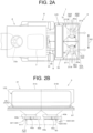
- Fig. 2 shows a plan view of a rear portion of the working machine 1 and a rear view of a working device 3.
- the working machine 1 includes a traveling vehicle (first moving entity) 2 and the working device (second moving entity) 3.
- the working machine 1 further includes a main battery 12M and a sub battery (storing device) 12S.
- the main battery 12M and the sub battery 12S store electric energy (energy source) for driving the traveling vehicle 2 and the working device 3.
- the in battery 12M and the sub battery 12S are loaded on the traveling vehicle 2 and the working device 3, respectively.
- the tractor 2 includes a vehicle body 4, a traveling device 5, and a coupling device 6.
- a front side (a left side in Fig. 1 ) of a driver seated on a driver seat 7 loaded on the vehicle body 4 will be described as a front side
- a rear side (a right side in Fig. 1 ) of the driver will be described as a rear side
- a left side (a front side in Fig. 1 ) of the driver will be described as a left side
- a right side (a back side in Fig. 1 ) of the driver will be described as a right side.
- a horizontal direction K2 (see Fig. 2 ), which is a direction orthogonal to a front-rear direction K1 (see Fig. 1 ), will be described as a vehicle width direction.
- the main battery 12M includes a battery pack, an electric unit (a relay, a fuse, or the like), and cooling means inside a substantially rectangular parallelepiped casing.
- the battery pack includes a plurality of battery modules.
- the battery module includes a plurality of cells.
- the main battery 12M configured as described above is a battery capable of charging and discharging electric energy, specifically, a lithium ion battery. The electric energy stored in the main battery 12M is transmitted to a main power supply path P1 described below.
- the electric motor 11 and the main battery 12M are loaded on the vehicle body frame 8 and disposed at a front portion of the vehicle body 4.
- the clutch housing 9 is connected to a rear portion of the electric motor 11 and houses a clutch.
- the transmission case 10 is coupled to a rear portion of the clutch housing 9 and extends rearward.
- the transmission case 10 houses a transmission device 13, a rear wheel differential device 14, and the like described below.
- the traveling device 5 includes a front wheel 5F provided at the front portion of the vehicle body 4 and a rear wheel 5R provided at the rear portion of the vehicle body 4.
- the front wheel 5F is supported by the vehicle body frame 8.
- the rear wheel 5R is supported by an output shaft of the rear wheel differential device 14.
- the traveling device 5 is a tire type in the present embodiment, and may be a crawler type.
- the coupling device 6 is a device for coupling the working device 3 to a rear portion of the tractor 2.
- the coupling device 6 includes a three-point link mechanism.
- a configuration of the coupling device 6 is not particularly limited as long as the working device 3 can be coupled to a rear portion of the traveling vehicle 2.
- the traveling vehicle 2 is a pickup truck
- the coupling device 6 couples the working device 3 by a mechanism other than the three-point link mechanism.
- the coupling device 6 is coupled to a rear portion of the transmission case 10.
- the coupling device 6 includes a lift arm 6A, a three-point link mechanism 6B, and a shift cylinder 6C.
- the lift arm 6A includes a first lift arm 6AL and a second lift arm 6AR.
- the first lift arm 6AL is disposed on one side (left side) in the vehicle width direction.
- the second lift arm 6AR is disposed on the other side (right side) in the vehicle width direction.
- Front end portions of the first lift arm 6AL and the second lift arm 6AR are pivotally supported by a horizontal shaft 6D supported on an upper portion of the transmission case 10, and extend rearward.
- the three-point link mechanism 6B includes a top link 6B1, a lower link 6B2, and a lift rod 6B3.
- the top link 6B1 is disposed between the first lift arm 6AL and the second lift arm 6AR, and has a front end portion pivotally supported by a first pivot support portion 10b provided on an upper portion of the transmission case 10.
- the lower link 6B2 includes a first lower link 6B2L and a second lower link 6B2R. Front end portions of the first lower link 6B2L and the second lower link 6B2R are pivotally supported by second pivot support portions 10c provided on a lower left portion and a lower right portion of the transmission case 10.
- the lift rod 6B3 includes a first lift rod 6B3L and a second lift rod 6B3R.
- An upper end portion of the first lift rod 6B3L is connected to a rear end portion of the first lift arm 6AL, and a lower end portion of the first lift rod 6B3L is connected to a middle portion of the first lower link 6B2L in a length direction.
- An upper end portion of the second lift rod 6B3R is connected to a rear end portion of the second lift arm 6AR, and a lower end portion of the second lift rod 6B3R is connected to a middle portion of the second lower link 6B2R in the length direction.
- a joint that can couple the working device 3 is provided at a rear end portion of the top link 6B1 and a rear end portion of the lower link 6B2.
- the lift cylinder 6C is a hydraulic cylinder.
- the lift cylinder 6C includes a first lift cylinder 6CL and a second lift cylinder 6CR. One end portion of the first lift cylinder 6CL is connected to the first lift arm 6AL, and the other end portion of the first lift cylinder 6CL is connected to a lower left portion of the transmission case 10.
- One end portion of the second lift cylinder 6CR is connected to the second lift arm 6AR, and the other end portion of the second lift cylinder 6CR is connected to the lower right portion of the transmission case 10.
- An electromagnetic control valve is connected to the first lift cylinder 6CL and the second lift cylinder 6CR.
- the electromagnetic control valve can drive (expand and contract) the first lift cylinder 6CL and the second lift cylinder 6CR based on a control signal from a control device 20.
- a height of the working device 3 and an inclination of the working device 3 in the vehicle width direction (a difference between a height of a right portion and a height of a left portion) can be adjusted.
- both the first lift cylinder 6CL and the second lift cylinder 6CR are similarly driven.
- one of the first lift cylinder 6CL and the second lift cylinder 6CR is driven. Specifically, the lift cylinder disposed on a side where the height of the working device 3 is small is expanded, or the lift cylinder disposed on a side where the height is large is driven to be contracted.
- the working device 3 is, for example, a spreading device for spreading a spread object (particulate matter or the like) such as a fertilizer or a chemical, a tilling device for tilling, a harvesting device for harvesting, a mowing device for mowing grass or the like, a distributing device for distributing grass or the like, a grass gathering device for gathering grass or the like, and a shaping device for shaping grass or the like.
- Figs. 1 and 2 show an example in which the spreading device is attached as the working device 3. The working device 3 is described in detail below.
- the tractor 2 includes a PTO shaft 19.
- the PTO shaft 19 transmits power from the electric motor 11 that drives the tractor 2 to the working device 3 and the like.
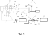
- the electric motor 11 is electrically connected to the main battery 12M and the sub battery 12S via an inverter. More specifically, the main battery 12M and the electric motor 11 are connected by the main power supply path P.
- the main power supply path P is, for example, a harness or the like.
- an inverter is interposed on a side of the main power supply path P that is adjacent to the electric motor 11.
- a switching device 60 is interposed in the main power supply path P closer to the main battery 12M than the inverter.
- a sub power supply path P1 extends toward a connector 61 so as to branch from the switching device 60.
- the sub power supply path P1 is, for example, a harness or the like.
- the connector 61 is provided in the tractor 2 (vehicle body 4) as shown in Fig. 4 .
- the connector 61 enables connection to the sub power supply path P1 from the outside.
- the connector 61 is connected to one end portion of the sub power supply path P1 on a side opposite to the switching device 60.
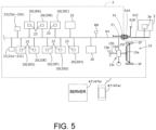
- the connector 61 is also connected to an in-vehicle network N1 in parallel with the sub power supply path P1 (see Fig. 5 ).
- the connector 61 is detachably connected to a cable connector 61A.
- a power supply cable (supply path) 61B connected to the sub battery 12S and a communication cable (communication path) 61C connected to the working device 3 is connected to the cable connector 61A.
- the connector 61 is provided at the rear portion of the tractor 2, and is located above a front end portion of the top link 6B1 of the coupling device 6 and a front end portion of the lift arm 6A.
- the connector 61 is provided between the first lift arm 6AL and the second lift arm 6AR in the vehicle width direction.
- the connector 61 disposed as described above faces the working device 3.
- the connector 61 is provided in the tractor 2, but instead, the connector 61 may be provided in the working device 3, intermediate portions of the power supply cable 61B and the communication cable 61C, or the like.
- the switching device 60 In a state in which the cable connector 61A is connected to the connector 61, the switching device 60 operates in two modes based on a control signal from the control device 20. In one mode, the switching device 60 maintains electrical connection between the main battery 12M and the electric motor 11, and cuts off electrical connection between the sub battery 12S and the electric motor 11. In a case where a switching instruction is issued to the switching device 60 in the one mode, the switching device 60 forms the electrical connection between the sub battery 12S and the electric motor 11, and cuts off the electrical connection between the main battery 12M and the electric motor 11 in the other mode.
- the switching device 60 operating in this manner is, for example, a solid state relay or the like.
- electric energy for driving is supplied to the electric motor 11 from the main battery 12M or the sub battery 12S via the inverter. More specifically, in the one mode of the switching device 60, the electric energy is supplied from the main battery 12M to the electric motor 11 via the main power supply path P. In the other mode of the switching device 60, the electric energy is supplied from the sub battery 12S to the electric motor 11 via the power supply cable 61B, the connector 61, the sub power supply path P1, and the main power supply path P. The electric energy supplied to the electric motor 11 is adjusted by controlling the inverter according to a control signal from the control device 20, and ON/OFF of the electric motor 11 and a rotation speed of the output shaft are controlled.
- the sub battery 12S is described in detail below.
- the PTO shaft 19 protrudes rearward from the transmission case 10.
- the transmission device 13 includes the main shaft (propulsion shaft) 13a, a main transmission unit 13b, an auxiliary transmission unit 13c, a shuttle unit 13d, and a PTO power transmission unit 13e.
- the propulsion shaft 13a is rotatably supported by a housing case of the transmission device 13. Power from the output shaft of the electric motor 11 is transmitted to the propulsion shaft 13a.
- the main transmission unit 13b includes a plurality of gears and a shifter that changes connection of the gears.
- the main transmission unit 13b changes and outputs (shifts) a rotational speed input from the propulsion shaft 13a by appropriately changing connection (meshing) of the plurality of gears with the shifter.
- the auxiliary transmission unit 13c includes a plurality of gears and a shifter that changes connection of the gears.
- the auxiliary transmission unit 13c changes and outputs (shifts) a rotational speed input from the main transmission unit 13b by appropriately changing connection (meshing) of the plurality of gears with the shifter.
- the shuttle unit 13d includes a shuttle shaft 16 and a forward/backward switch unit 17.
- the power output from the auxiliary transmission unit 13c is transmitted to the shuttle shaft 16 via a gear or the like.
- the rear wheel differential device 14 is provided on the shuttle shaft 16.
- a rear axle supporting the rear wheels 5R is rotatably supported by the rear wheel differential device 14.
- the forward/backward switching unit 17 is configured by, for example, a clutch such as a hydraulic clutch or an electric clutch, and switches a rotation direction of the shuttle shaft 16, that is, forward movement and backward movement of the tractor 2, by turning on and off the clutch.
- the PTO power transmission unit 13e includes a PTO clutch 18 and the PTO shaft 19.
- the PTO shaft 19 is rotatably supported, and can transmit the power from the propulsion shaft 13a.
- the PTO shaft 19 includes a PTO propulsion shaft 19a and a PTO output shaft 19b.
- the PTO propulsion shaft 19a is connected to the PTO output shaft 19b via a PTO transmission unit 19c.
- the PTO propulsion shaft 19a may be connected to the PTO output shaft 19b without passing through the PTO transmission unit 19c.
- An output of the PTO output shaft 19b is transmitted to a power transmission mechanism 50 of the working device 3 described below.
- the PTO transmission unit 19c can change a rotational speed of the PTO propulsion shaft 19a and transmit the rotation to the PTO output shaft 19b by an operation unit such as a PTO shift lever.
- the PTO transmission unit 19c includes, for example, a transmission actuator such as an electromagnetic solenoid or an electric motor capable of operating the operation unit based on a control signal from the control device 20.
- the PTO clutch 18 is a clutch capable of switching between a connected state in which the power of the propulsion shaft 13a is transmitted to the PTO shaft 19 and a disconnected state in which the power of the propulsion shaft 13a is not transmitted to the PTO shaft 19.
- the PTO clutch 18 is provided between the propulsion shaft 13a and the PTO propulsion shaft 19a.
- the PTO clutch 18 is configured by a hydraulic clutch, an electric clutch, or the like, and can switch between a state in which the power of the propulsion shaft 13a (the power of the electric motor 11) is transmitted to the PTO shaft 19 and a state in which the power of the propulsion shaft 13a is not transmitted to the PTO shaft 19 by being turned on and off.
- the tractor 2 includes a steering device 15.
- the steering device 15 includes a steering wheel 15a, a rotation shaft (steering shaft) 15b that rotates with the rotation of the steering wheel 15a, and an assist mechanism (power steering mechanism) 15c that assists the steering of the steering wheel 15a.
- the assist mechanism 15c includes a control valve 15d and a steering cylinder 15e.
- the control valve 15d is, for example, a three-position switching valve that can be switched by movement of a spool or the like.
- the control valve 15d can also be switched by steering of the steering shaft 15b.
- the steering cylinder 15e is connected to an arm (knuckle arm) 15f that changes an orientation of the front wheel 5F.
- a switching position and an opening degree of the control valve 15d are switched according to the steering wheel 15a, and a steering direction of the front wheel 5F can be changed by expanding and contracting the steering cylinder 15e to the left or right according to the switching position and the opening degree of the control valve 15d.
- the steering device 15 described above is an example, and is not limited to the above-described configuration.
- the tractor 2 includes a plurality of detection devices 21.
- the plurality of detection devices 21 are devices that detect a state of the tractor 2, and include, for example, a water temperature sensor 21a that detects a water temperature, a main battery sensor 21b that detects a voltage of the main battery 12M, a motor rotation sensor 21c that detects a rotation speed of the electric motor 11, an accelerator pedal sensor 21d that detects an operation amount of an accelerator pedal, a steering angle sensor 21e that detects a steering angle of the steering device 15, an angle sensor 21f that detects angles of the lift arms 6A and 7A, an inclination detection sensor 21g that detects an inclination of the vehicle body 4 in the width direction (rightward or leftward), a speed sensor 21h that detects a vehicle speed (speed) of the vehicle body 4, a PTO rotation sensor 21i that detects a rotation speed of the PTO shaft 19, a sub battery sensor 21j that detects a voltage of the sub battery 12S, a positioning sensor (positioning
- the positioning device 21k can detect its own position (positioning information including latitude and longitude) by a satellite positioning system (positioning satellite) such as D-GPS, GPS, GLONASS, BeiDou, Galileo, or Michibiki. That is, the positioning device 21k receives a satellite signal (a position of the positioning satellite, a transmission time, correction information, or the like) transmitted from the positioning satellite, and detects a position (for example, latitude and longitude) of the tractor 2, that is, the position of the vehicle body 4, based on the satellite signal.
- the positioning device 21k includes a reception device and an inertial measurement unit (IMU).
- IMU inertial measurement unit
- the reception device is a device that includes an antenna or the like and receives the satellite signal transmitted from the positioning satellite, and is attached to the vehicle body 4 separately from the inertial measurement unit.
- the reception device is attached to the vehicle body 4. Note that an attachment location of the reception device is not limited to that in the embodiment.
- the inertial measurement unit includes an acceleration sensor that detects an acceleration, a gyro sensor that detects an angular velocity, and the like, and is provided on a lower side of the vehicle body 4, for example, the driver seat 4a.
- the inertial measurement unit can detect a roll angle, a pitch angle, a yaw angle, and the like of the vehicle body 4.
- the speed sensor 21h detects the vehicle speed by converting, for example, a rotation speed of an axle of the front wheels 5F, the rotation speed of the axle of the front wheels 5F, a rotation speed of the front wheels 5F, a rotation speed of the rear wheels 5R, and the like into the vehicle speed.
- the speed sensor 21h can also detect a rotation direction of any one of the axle of the front wheels 5F, the axle of the rear wheels 5R, the front wheels 5F, and the rear wheels 5R, and can also detect whether or not the tractor 2 (vehicle body 4) is moving forward or backward.
- the above-described detection device 21 is an example, and is not limited to the above-described sensor.
- the tractor 2 also includes a plurality of operation members 22.
- the plurality of operation members 22 include a shuttle lever 22a that switches forward movement or backward movement of the vehicle body 4, an ignition switch 22b that starts the prime mover 11 and the like, a PTO shift lever 22c that sets the rotation speed of the PTO shaft 19, a shift changeover switch 22d that switches between automatic shift and manual shift, a shift lever 22e that manually switches a shift stage (shift level) of the transmission device 13, an accelerator 22f that increases or decreases the vehicle speed, a pump switch 22g that operates lifting and lowering of the coupling device 6, a height setting dial 22h that sets an upper limit of an operation of the coupling device 6, a vehicle speed lever 22i that sets the vehicle speed, a hydraulic operation tool 22j, a rotation setting tool 22k that sets an upper limit of a rotation speed of the prime mover rotation, and the like.
- Setting tools such as the shift changeover switch 22d, the height setting dial 22h, and the rotation setting tool 22k are provided in a console box provided on a side of the driver seat 4a.
- An operation of the vehicle body 4 can be set by the driver operating the setting tool (the shift changeover switch 22d, the height setting dial 22h, or the rotation setting tool 22k).
- the above-described operation member 22 is an example, and is not limited to the above-described configuration.
- the tractor 2 includes a plurality of control devices 20.
- the control device 20 is a device that performs various controls of the tractor 2, and is a central processing unit (CPU), an electric/electronic circuit, or the like.
- the control device 20 includes a storage device 23 that stores various information such as a control program, identification information, and the like.
- the storage device 23 is configured by a nonvolatile memory or the like. That is, the plurality of control devices 20 are electrical components including the storage device 23.
- the plurality of control devices 20 include a shift control device 20A, a motor control device 20B, a PTO control device 20C, a lifting/lowering control device 20D, an automatic steering control device 20E, a pose control device 20F, a battery switching control device 20G, and an automated traveling control unit 20H.
- the control device 20 does not need to include all of the shift control device 20A, the motor control device 20B, the PTO control device 20C, the lifting/lowering control device 20D, the automatic steering control device 20E, the pose control device 20F, the battery switching control device 20G, and the automated traveling control unit 20H, and may be provided according to a specification of the tractor.
- the shift control device 20A, the motor control device 20B, the PTO control device 20C, the lifting/lowering control device 20D, the automatic steering control device 20E, the pose control device 20F, the battery charge/discharge control device 20G, the automated traveling control unit 20H may be provided in an integrated control device.
- the shift control device 20A performs shift control. In the shift control, in a case where an automatic shift function is enabled, any one of the main transmission unit 13b or the auxiliary transmission unit 13c is automatically switched according to the state of the tractor 2, and the shift stage (shift level) of the transmission device 13 is automatically changed to a predetermined shift stage (shift level).
- any one of the main transmission unit 13b or the auxiliary transmission unit 13c is automatically switched according to the shift stage (shift level) set by the shift lever 22e to change the shift stage of the transmission device 13.
- the shift control device 20A performs control (travel switching control) in a travel driving state (an operation of the traveling device 5) of the traveling device 5.
- control travel switching control
- the forward/backward switching unit 17 of shuttle unit 13d is switched to forward movement to move the vehicle body 4 forward.
- the forward/backward switching unit 17 of shuttle unit 13d is switched to backward movement to move the vehicle body 4 backward.
- the motor control device 20B controls the electric motor 11 by inverter control.
- the electric motor control in a case where the ignition switch 22b is operated to be turned on, the electric motor 11 is started through predetermined processing, and in a case where the ignition switch 22b is operated to be turned off, the driving of the electric motor 11 is stopped.
- the electric motor control in a case where the accelerator 22f is operated, the vehicle speed (speed) of the vehicle body 4 is changed by controlling the inverter to change the rotation speed of the electric motor 11 according to an operation amount of the accelerator 22f.
- the PTO control device 20C performs PTO control.
- the PTO control in a case where the PTO shift lever 22c is operated, the rotational speed (PTO rotational speed) of the PTO propulsion shaft 19a is changed by switching a PTO shift gear of the PTO transmission unit 19c.
- the lifting/lowering control device 20D performs lifting/lowering control in the coupling device 6.
- a control valve is controlled to expand the shift cylinder 6C and lift a rear end portion (an end portion adjacent to the working device 3) of the lift arm 6A.
- the control valve is controlled to contract the shift cylinder 6C and lower the rear end portion (the end portion adjacent to the working device 3) of the lift arm 6A.
- the control valve In the lifting/lowering control, in a case where a backup function is enabled, the control valve is automatically controlled when the vehicle body 4 moves backward to expand the shift cylinder 6C and lift the rear end portion (the end portion adjacent to the working device 3) of the lift arm 6A. In the lifting/lowering control, in a case where an auto-up function is enabled and the steering angle of the steering device 15 becomes equal to or greater than a predetermined value, the control valve is automatically controlled to expand the shift cylinder 6C and lift the rear end portion (the end portion adjacent to the working device 3) of the lift arm 6A.
- the automatic steering control device 20E performs automatic steering control.
- the steering device 15 is automatically controlled to change the steering direction of the front wheel 5F such that the vehicle body 4 travels along a set scheduled travel route.
- the pose control device 20F performs pose control.
- pose control in a case of adjusting the height of the working device 3, lengths of both the first lift cylinder 6CL and the second lift cylinder 6CR are fixed to predetermined lengths by outputting a control signal to a control valve.
- pose control in a case of adjusting the inclination in the vehicle width direction (the difference between the height of the right portion and the height of the left portion), any one of the first lift cylinder 6CL and the second lift cylinder 6CR is driven by outputting a control signal to the control valve.
- the battery switching control device 20G performs battery switching control.
- the battery that supplies the electric energy to the electric motor 11 is switched to any one of the main battery 12M and the sub battery 12S.
- the switching device 60 in a state in which the electric motor 11 and the main battery 12M are connected to each other and the sub battery 12S is cut off by the switching device 60, the switching device 60 is controlled to connect the electric motor 11 and the sub battery 12S and cut off the main battery 12M when a predetermined condition is satisfied.
- the predetermined condition may be satisfied, for example, when a remaining level of the main battery 12M is equal to or lower than a predetermined value and a remaining level of the sub battery 12S is equal to or higher than a predetermined value.
- the remaining level of the main battery 12M is calculated based on a voltage or the like of the main battery 12M detected by the main battery sensor 21b.
- the remaining level of the sub battery 12S is calculated based on a voltage or the like of the sub battery 12S detected by the sub battery sensor 21j.
- the driving changeover switch 65 is connected to the tractor 2.
- the driving changeover switch 65 is a switch that can be switched to be turned on and off, and can set the automated traveling control unit 20H to an automated driving mode when being turned on, and can set the automated traveling control unit 20H to a manual driving mode when being turned off.
- the automated traveling control unit 20H controls automated driving of the vehicle body 4.
- the automated traveling control unit 20H starts the automated driving in the automated driving mode.
- the steering angle of the steering device 15 is changed based on a deviation between the position of the vehicle body 4 and the set scheduled travel route.
- the setting of the steering angle in the automated driving in the above-described embodiment is an example and is not limited.
- the automated traveling control unit 20H automatically changes the shift stage of the transmission device 13, the rotation speed of the electric motor 11, and the like such that the current vehicle speed of the tractor 2 matches the vehicle speed corresponding to the scheduled travel route.
- the tractor 2 includes a communication device 26.
- the communication device 26 is a communication device (communication module) that performs any one of direct communication and indirect communication with an external device 47, and can perform radio communication by, for example, wireless fidelity (Wi-Fi) (registered trademark) of the IEEE 802.11 series which is a communication standard, Bluetooth (registered trademark) low energy (BLE), low power wide area (LPWA), low-power wide-area network (LPWAN), or the like.
- Wi-Fi wireless fidelity
- BLE Bluetooth
- LPWA low power wide area
- LPWAN low-power wide-area network
- the communication device 26 may be a communication device (communication module) that performs radio communication by a mobile phone communication network, a data communication network, or the like.
- the external device 47 is, for example, a portable type terminal (portable terminal) 47a such as a tablet, a smartphone, or a personal digital assistant (PDA), or a fixed type terminal (fixed terminal) 47b such as a fixed type computer such as a personal computer or a server.
- the tractor 2 includes a display device 25.
- the display device 25 is a device that displays various information regarding the tractor 2.
- the display device 25 is installed in the vicinity of the driver seat 4a, so that the driver can confirm a displayed content.
- the display device 25 is a meter panel device that displays driving information, an auxiliary panel device that performs various settings related to the working machine, and the like.
- the tractor 2 (vehicle body 4) includes the in-vehicle network N1.
- the in-vehicle network N1 is a network such as a controller area network (CAN), a local interconnect network (LIN), media oriented system transport (MOST), FlexRay, or ISO11783 (ISOBUS).
- the plurality of control devices 20, the plurality of detection devices 21, the plurality of operation members 22, the communication device 26, and the display device 25 are connected to the in-vehicle network N1.
- the connector 61 provided on the rear side of the tractor 2 (vehicle body 4) enables connection from the outside to the in-vehicle network N1.
- the communication cable 61C connects the tractor 2 and the spreading device 3. One end portion of the communication cable 61C is connected to the cable connector 61A, and the other end portion of the communication cable 61C is connected to the working device 3.
- the power supply cable 61B connects the tractor 2 and the sub battery 12S. One end portion of the power supply cable 61B is connected to the cable connector 61A, and the other end portion of the power supply cable 61B is connected to the sub battery 12S. In this manner, the cable connector 61A aggregates one end portions of the power supply cable 61B and the communication cable 61C.
- the connector 61 and the cable connector 61A are attachable to and detachable from each other. Shapes of the connector 61 and the cable connector 61A are not limited as long as the power supply cable 61B and the communication cable 61C are attachable and detachable.
- the connector 61 may include a power supply male pin connected to a terminal end of the working device supply path P4 and a communication male pin connected to a terminal end of the in-vehicle network N1
- the cable connector 61A may include a power supply female pin connected to one end portion of the power supply cable 61B and a communication female pin connected to one end portion of the communication cable 61C.
- the male pins and female pins may be provided in a reverse way.
- the connector 61 and the cable connector 61A When the connector 61 and the cable connector 61A are mounted on each other, the power supply male pin and the power supply female pin are connected to each other, and the communication male pin and the communication female pin are connected to each other. Accordingly, the electric energy can be supplied from the sub battery 12S to the tractor 2 (vehicle body 4) via the connector 61, and a communication signal can be transmitted between the tractor 2 and the working device 3.
- the connector 61 and the cable connector 61A are separated from each other, the connection between the power supply male pin and the power supply female pin and the connection between the communication male pin and the communication female pin are released.
- the connector 61 may be closed by a lid body.
- the power supply cable 61B and the communication cable 61C may be bound by a binding tool 109 so as to be integrated with each other on a side adjacent to the cable connector 61A, and may be branched from each other while extending rearward from the cable connector 61A.
- the power supply cable 61B and the communication cable 61C may be integrally routed at a bound portion, and may be separately routed behind a branch portion.
- the bound portion of the power supply cable 61B and the communication cable 61C is routed toward the working device 3 through above the coupling device 6 (above the top link 6B1). Behind the branch portion of the power supply cable 61B and the communication cable 61C, the routing is separately adjusted according to connection positions of the sub battery 12S and the working device 3.
- the working device 3 is a device that performs the agricultural work.
- the working device 3 is a device that performs work on the farm field.
- the working device 3 is driven by transmission of the power from the PTO shaft 19 of the tractor 2.
- a spreading device that spreads a spread object in the farm field a seeding device that sows seeds in the farm field, a shaping device (baler) that gathers and shapes harvested crops (grass or the like), and the like are suitably used.
- a fertilizer spreading device preader
- a chemical spreading device for spreading a chemical (chemical solution) to the farm field, or the like is used.
- the seeding device for example, a seeder such as a drill seeder for row planting, a planter for sowing seeds at regular intervals, or the like is used.
- a seeder such as a drill seeder for row planting, a planter for sowing seeds at regular intervals, or the like is used.
- the working device 3 since the working device 3 is the spreading device, the working device 3 will be described below as the spreading device 3.
- the spreading device 3 includes a housing unit 31 and a spreading unit 32.
- the housing unit 31 stores the spread object (a fertilizer, a pesticide, or the like) to be spread to the farm field.
- the housing unit 31 is configured by a hopper having a substantially inverted pyramid shape.
- the hopper includes a first hopper 31A and a second hopper 31B.
- the first hopper 31A is disposed on one side (left side) in the vehicle width direction.
- the second hopper 31B is disposed on the other side (right side) in the vehicle width direction.
- the number of hoppers is not limited.
- the housing unit 31 has an inlet for the spread object at an upper end and has an outlet for discharging the spread object at a lower end.
- the number of outlets is not limited, and is set according to the number of rotating bodies (disks) 40 described below in the present embodiment. Specifically, the number of rotating bodies 40 is two, and the number of outlets is also two. Note that the number of rotating bodies 40 may be two, and the number of outlets may be one.
- the spreading unit 32 is a working unit of the working device 3, and performs the agricultural work (spreading of the spread object such as a fertilizer or a chemical) by rotating.
- the spreading unit 32 spreads the spread object stored in the housing unit 31.
- the spreading unit 32 is provided below the housing unit 31.
- the spreading unit 32 includes at least two or more spreading units. It is preferable that at least two or more spreading units have different spreading directions, but the at least two or more spreading units may include spreading units having the same spreading direction.
- Fig. 2(a) is a plan view of a rear portion of the working machine 1
- Fig. 2(b) is a rear view of the spreading device 3.
- the spreading unit 32 includes a first spreading unit 321 and a second spreading unit 322. That is, in the present embodiment, the number of spreading units 32 is two. However, the number of spreading units 32 is not limited to two, and may be three or more. The number of spreading units 32 and the number of rotating bodies 40 are the same as each other.
- the first spreading unit 321 and the second spreading unit 322 are provided side by side in the vehicle width direction. Hereinafter, the two spreading units (the first spreading unit 321 and the second spreading unit 322) will be described.
- the first spreading unit 321 is disposed on one side (left side) in the vehicle width direction.
- the second spreading unit 322 is disposed on the other side (right side) in the vehicle width direction.
- the first spreading unit 321 includes a first rotating body 410 and a first shutter device 411.
- the first rotating body 410 has a disk shape and rotates about a central axis 40a extending in a longitudinal direction (vertical direction).
- a plurality of rotating blades (blade members) 40b are attached to an upper surface of the first rotating body 410.
- the rotating blade 40b rotates about the central axis 40a together with the first rotating body 410.
- the plurality of rotating blades 40b are disposed at intervals in a circumferential direction, and extend radially outward from the vicinity of the central axis 40a. As the first rotating body 410 rotates about the central axis 40a, the rotating blades 40b hit and radially scatter the spread object falling from a first outlet 71 outward (radially outward) .
- the first shutter device 411 includes a shutter and an electric motor (not shown).
- the shutter is attached to the first outlet 311 on one side of the housing portion 31, and can change an area (opening degree) of the first outlet 311 by moving.
- the electric motor is a stepping motor or the like, and is coupled to the shutter.
- the first shutter device 411 changes the opening degree of the first outlet 311 by moving the shutter by driving the electric motor. As a result, a spread amount of the spread object by the first spreading unit 321 is adjusted.
- the second spreading unit 322 includes a second rotating body 420 and a second shutter device 421. Since a configuration of the second rotating body 420 is similar to that of the first rotating body 410, the description thereof will be omitted. A configuration of the second shutter device 421 is the same as that of the first shutter device 411 except that the shutter is attached to the second outlet 312 on the other side of the housing portion 31. The second shutter device 421 can adjust a spread amount of the spread object by the second spreading unit 322 by changing an opening degree of the second outlet 312.
- the first rotating body 410 and the second rotating body 420 are provided side by side in the vehicle width direction and rotate in directions different from each other.
- the first rotating body 410 rotates in a clockwise direction and the second rotating body 420 rotates in a counterclockwise direction in plan view as indicated by black arrows in Fig. 2 .
- the first rotating body 410 is disposed below the first outlet 311 of the housing portion 31.
- the spread object falling from the first outlet 311 is spread by the rotating first rotating body 410.
- the second rotating body 420 is disposed below the second outlet 312 of the housing portion 31.
- the spread object falling from the second outlet 312 is spread by the rotating second rotating body 420.
- the spreading directions of the first spreading unit 321 and the second spreading unit 322 are different from each other.
- the spreading direction of the first spreading unit 321 is one side in the vehicle width direction and the rear side.
- the spreading direction of the second spreading unit 322 is the other side in the vehicle width direction and the rear side.
- the main spreading direction of the first spreading unit 321 is the left side and a rear left side
- the main spreading direction of the second spreading unit 322 is the right side and a rear right side as indicated by outlined arrows in Fig. 2 .
- the direction indicated by the outlined arrow is the main spreading direction, and in actual implementation, spreading is performed in a fan shape including the direction indicated by the outlined arrow.
- the spreading device 3 includes a power transmission mechanism 50.
- the power transmission mechanism 50 includes an input/output shaft, a gear, and the like, receives the power supplied from the electric motor 11, and transmits the input power to the spreading unit (working unit) 32.
- the power transmission mechanism 50 is a mechanism capable of transmitting the power from the PTO shaft 19 to the first rotating body 410 and the second rotating body 420. That is, the first rotating body 410 and the second rotating body 420 can be rotated by the power from the electric motor 11. In addition, rotational speeds of the first rotating body 410 and the second rotating body 420 can be changed by a transmission unit of the power transmission mechanism 50. It is spread.
- the housing unit 31, the spreading unit 32, and the power transmission mechanism 50 configured as described above are supported by a frame 97.
- the spreading device 3 includes the frame 97.
- a configuration of the frame 97 is not limited to the shown configuration.
- directions related to the frame 97 are based on a state in which the spreading device 3 is coupled to the rear portion of the tractor 2.
- the frame 97 includes an upper frame 97A, a lower frame 97B, a coupling portion 98, and a battery loading portion 99.
- the frame 97 including the battery loading portion 99 is made of a metal material such as a steel material having high thermal conductivity as a whole.
- the upper frame 97A is a frame that supports the housing portion 31, and is located above the spreading unit 32.
- the upper frame 97A is formed in a substantially rectangular frame shape in plan view.
- the housing portion 31 (the first hopper 31A and the second hopper 31B) is provided behind the upper frame 97A in plan view.
- the battery loading portion 99 is installed at an upper end portion of the upper frame 97A and in front of the housing portion 31.
- the battery loading portion 99 is formed in a rectangular plate shape, and a long side and a short side extend in the vehicle width direction and the front-rear direction, respectively.
- An upper surface of the battery loading portion 99 is configured to be capable of loading the sub battery 12S.
- the sub battery 12S is not loaded on the tractor 2, but is loaded by effectively using a space of the spreading device 3. Therefore, it is not necessary to newly provide a configuration for loading the sub battery 12S on the tractor 2, and the sub battery 12S can be easily loaded. In addition, it is possible to suppress an increase in size of the entire working machine. In addition, a loading position of the sub battery 12S can be brought close to the center of gravity, and a weight balance of the entire working machine can be suppressed from being lost. In addition, since the loading position of the sub battery 12S is on a front side of the housing portion 31, input of a material to the spreading device 3 is not interfered. In addition, even when heat generation from the sub battery 12S increases due to a large degree of discharge of the sub battery 12S or the like, the frame 97 can be used as a heat sink via the battery loading portion 99 made of a metal material.
- the lower frame 97B is disposed below the upper frame 97A.
- the spreading unit 32 (the first spreading unit 321 and the second spreading unit 322) and the power transmission mechanism 50 are supported by the lower frame 97B via a bracket so as to be located in a hollow portion having the substantially rectangular frame shape.
- the coupling portion 98 is provided at a position corresponding to a rear end portion of the three-point link mechanism 6B (the top link 6B1, the first lower link 6B2L, and the second lower link 6B2R) of the coupling portion 6 at a front end portion of the frame 97.
- the coupling portion 98 is detachably coupled to the coupling device 6 provided at the rear portion of the tractor 2. By coupling the coupling portion 98 to the coupling device 6, the spreading device 3 is detachably coupled to the rear portion of the tractor 2.
- the spreading device 3 includes a work control device 3a.
- the work control device 3a is a device that performs various controls of the spreading device 3, and is a CPU, an electric/electronic circuit, or the like.
- the work control device 3a includes a storage device that stores various information such as a control program, identification information, and the like.
- the storage device is configured by a nonvolatile memory or the like.
- the work control device 3a is connected to the in-vehicle network N1 via the communication cable 61C and the connector 61 connecting the spreading device 3 and the tractor 2. As a result, a communication signal can be transmitted and received between the tractor 2 and the spreading device 3.
- the sub battery 12S is loaded in addition to the main battery 12M.
- a configuration of the sub battery 12S is different from a configuration of the main battery 12M in that the sub battery 12S is connected to the power supply cable 61B and the stored electric energy is sent to the power supply cable 61B. Except for this point, the configuration of the sub battery 12S is equivalent to the configuration of the main battery 12M.
- the sub battery 12S is loaded in addition to the main battery 12M.
- a package capable of storing the energy source may be mounted instead of the sub battery 12S.
- a hydrogen tank, a liquified petroleum gas (LPG) tank, or the like may be used.
- the hydrogen tank is loaded on the working device 3, for example, a fuel cell that generates electric power with hydrogen and oxygen in the air may be mounted on the tractor 2, and hydrogen from the tank may be supplied to the fuel cell.
- a fuel cell that generates electric power with hydrogen and oxygen in the air
- hydrogen from the tank may be supplied to the fuel cell.
- the LPG tank is loaded on the working device 3, for example, a generator that generates electric power by a gas engine may be mounted on the tractor 2, and gas from the tank may be supplied to the gas engine.
- the power supply cable 61B may be replaced with a fuel pipe.
- the sub battery 12S is loaded on the spreading device 3. More specifically, the sub battery 12S is detachably loaded on the upper surface of the battery loading portion 99 of the frame 97 via an attachment. In a case where the loaded sub battery 12S is used up, the sub battery 12S is detached from the battery loading portion 99, and a new fully charged sub battery 12S is loaded on the battery loading portion 99. That is, the sub battery 12S is a replaceable battery.
- the main battery 12M In the working machine 1 configured as described above, in a state in which the sub battery 12S is loaded on the spreading device 3 and the spreading device 3 is coupled to the tractor 2, traveling and the work are started by turning on an ignition. At this time, the remaining level of the main battery 12M is higher than a predetermined value. Therefore, it is assumed that the remaining level of the main battery 12M is sufficient, and the main battery 12M is connected to the electric motor 11. As a result, the electric energy from the main battery 12M is supplied to the electric motor 11, and the electric motor 11 is driven under inverter control. A driving force of the electric motor 11 is transmitted and converted to traveling of the tractor 2 and operation of the spreading device 3. As the traveling and work of the working machine 1 continue, the remaining level of the main battery 12M decreases. In this state, the sub battery 12S is not used.
- the battery switching control device 20G instructs the switching device 60 to perform the battery switching control.
- the sub battery 12S is connected to the electric motor 11 instead of the main battery 12M.
- the electric energy from the sub battery 12S is supplied to the electric motor 11, and the driving of the electric motor 11 can be continued. Therefore, the traveling and work can be continued according to a capacity of the sub battery 12S without being stopped in order to charge the main battery 12M whose remaining level has decreased.
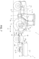
- Fig. 7 is an overall side view of a working machine 1 according to a second embodiment.
- Fig. 8 is a plan view of a rear portion of the working machine 1.
- a configuration of the working machine 1 according to the second embodiment is different from that of the first embodiment described above in that a towed trailer 80 on which a sub battery 12S is loaded is coupled to a tractor 2, and a spreading device 3 is coupled to the towed trailer 80.
- the other points are the same as the configuration of the first embodiment.
- differences of the second embodiment from the first embodiment will be described.
- the same or equivalent parts as those in the first embodiment are denoted by the same reference numerals, and the description thereof will be omitted.
- the working machine 1 includes the towed trailer 80 coupled to the spreading device (working device) 3.
- the sub battery 12S is coupled to the tractor 2 by being loaded on the towed trailer 80.
- the battery loading portion 99 according to the first embodiment is not provided in a frame 97 of the spreading device 3, and a volume occupied by a housing portion 31 with respect to the entire frame 97 is larger than that of the first embodiment. That is, in the second embodiment, the sub battery 12S is not loaded on the spreading device 3, and a volume corresponding to the sub battery 12S is allocated to the housing portion 31. Therefore, more materials such as fertilizers and pesticides can be housed.
- a drawbar 98A is provided in the coupling device 6 of the tractor 2.
- the drawbar 98A is disposed at a rear end portion of the coupling device 6 so as to expand rearward from a substantially central portion in the vehicle width direction.
- the drawbar 98A detachably connects the towed trailer 80 at a rear end portion.
- the towed trailer 80 includes a frame 81 and wheels 82.
- the frame 81 includes a coupling portion 81A and a battery loading portion 81B.
- the frame 81 including the battery loading portion 81B is made of a metal material such as a steel material having high thermal conductivity as a whole.
- the frame 81 is a frame for loading the sub battery 12S, and is located above an axle of the wheels 82.
- the frame 81 is formed in a substantially rectangular frame shape in plan view.
- the coupling portion 81A is provided at a position corresponding to the rear end portion of the drawbar 98A.
- the coupling portion 81A is detachably coupled to the drawbar 98A provided at the rear end portion of the coupling device 6 of the tractor 2.
- the coupling portion 81A is detachably coupled to a rear portion of the tractor 2.
- Two wheels 82 are provided at a lower portion of the frame 81.
- One wheel 82 is provided at each of left and right end portions of the axle extending in the vehicle width direction.
- the axle is rotatably supported by the frame 81, and when the towed trailer 80 is towed, the wheels 82 and the axle coaxially rotate, so that the towed trailer 80 can move in a towing direction.
- the towed trailer 80 is coupled to the drawbar 98A at the rear portion of the tractor 2 via the coupling portion 81A of the frame 81.
- a front end portion of a lower frame 97B is coupled to a rear end portion of the frame 81 of the towed trailer 80.
- the battery loading portion 81B is installed at an upper end portion of the frame 81.
- the battery loading portion 81B is formed in a rectangular plate shape, and a long side and a short side extend in the vehicle width direction and the front-rear direction, respectively.
- An upper surface of the battery loading portion 81B is configured to be capable of loading the sub battery 12S. More specifically, the sub battery 12S is detachably loaded on the upper surface of the battery loading portion 81B of the frame 81 via an attachment. In a case where the loaded sub battery 12S is used up, the sub battery 12S is detached from the battery loading portion 81B, and a new fully charged sub battery 12S is loaded on the battery loading portion 81B.
- a power supply cable 61B and a communication cable 61C are provided, the tractor 2 and the sub battery 12S are connected by the power supply cable 61B, and the tractor 2 and the spreading device 3 are connected by the communication cable 61C.
- the power supply cable 61B and the communication cable 61C are connected to a connector 61 provided in the tractor 2.
- the sub battery 12S is loaded on the towed trailer 80 without being loaded on the tractor 2.
- a loading space of the towed trailer 80 can be dedicated to loading the sub battery 12S, and more batteries can be loaded as compared with the first embodiment.
- the frame 81 can be used as a heat sink via the battery loading portion 81B made of a metal material.
- only one towed trailer 80 is coupled to a rear side of the tractor 2, but instead, a plurality of towed trailers 80 may be coupled to the rear side of the tractor 2 so as to be continuous.
- the sub battery 12S may be loaded on each of the plurality of towed trailers 80.
- the sub battery 12S may also be loaded on the spreading device 3.
- the working machine 1 includes the traveling vehicle 2 as the first moving entity, the working device 3 (and the towed trailer 80) as the second moving entity coupled to the first moving entity, and the sub battery 12S that is loaded on the second moving entity and stores the energy source for driving the traveling vehicle 2.
- the sub battery 12S is loaded on the working device 3 and/or the towed trailer 80 without being loaded on the traveling vehicle 2. Therefore, it is not necessary to newly provide a configuration for loading the sub battery 12S on the traveling vehicle 2, and the sub battery 12S can be easily loaded.
- the traveling and work can be continued according to the capacity of the sub battery 12S without being stopped in order to charge the main battery 12M whose remaining level has decreased. Therefore, as many sub batteries 12M that store the energy source can be loaded on the working machine 1 as possible and appropriately, and the stop of the traveling and work related to charging of the main battery 12M can be reduced.
- the second moving entity includes the working device 3 that performs the work, and the sub battery 12S is loaded on the working device 3. Accordingly, the sub battery 12S can be loaded by effectively using the space of the working device 3 without being loaded on the traveling vehicle 2, and it is possible to suppress an increase in size of the entire working machine. In addition, a loading position of the sub battery 12S can be brought close to the center of gravity, and a weight balance of the entire working machine can be suppressed from being lost.
- the second moving entity includes the working device 3 that performs the work, and the sub battery 12S is coupled to the working device 3 by being loaded on the towed trailer 80.
- the loading space of the towed trailer 80 can be dedicated to loading the sub battery 12S, and more batteries can be loaded.
- the working machine 1 includes the power supply cable 61B which is a path of the electric energy supplied from the sub battery 12S to the traveling vehicle 2, and the connector 61 that can connect and disconnect the power supply cable 61B, the connector 61 allowing supply of the electric energy when connected, and cutting off supply of the electric energy when disconnected.
- the length and the routing of the power supply cable 61B can be adjusted to give a degree of freedom to the loading position of the sub battery 12S.
- the sub battery 12S is loaded on the working device 3 or the towed trailer 80 in advance, and the connector 61 is connected at the time of coupling, or the sub battery 12S is loaded on the coupled working device 3 or the towed trailer 80 later and the connector 61 is connected, so that it is possible to give a degree of freedom to a process of loading the sub battery 12S.
- the connector 61 is provided in the traveling vehicle 2 so as to face the second moving entity coupled to the traveling vehicle 2.
- the connector 61 is provided at the rear portion of the tractor 2, and is located above the front end portion of the top link 6B1 of the coupling device 6 and the front end portion of the lift arm 6A.
- the connector 61 can be brought close to the sub battery 12S, and a necessary distance of the power supply cable 61B can be shortened.
- the routing of the power supply cable 61B is facilitated.
- a conduction resistance of the power supply cable 61B can be reduced.
- the connector 61 is disposed above the coupling device 6, so that interference between the coupling device 6 and the power supply cable 61B can be suppressed.
- the storing device is the sub battery 12S capable of charging and discharging the electric energy as the energy source
- the working device 3 is capable of receiving a signal from the traveling vehicle 2
- the working machine 1 includes the communication cable 61C that transmits the signal from the traveling vehicle 2 toward the working device 3, and the connector 61 that is capable of connecting and disconnecting each of the power supply cable 61B and the communication cable 61C, allows supply of the electric energy and transmission of the signal when connected, and cuts off supply of the electric energy and transmission of the signal when disconnected.
- a communication connector can be effectively used and integrated with a power supply connector, and the power supply cable 61B and the communication cable 61C can be connected and disconnected with one connector 61.
- the power supply cable 61B and the communication cable 61C can also be integrated by binding or the like, so that an effort of the routing can be reduced as compared with a case of separately routing the power supply cable 61B and the communication cable 61C.
Landscapes
- Engineering & Computer Science (AREA)
- Life Sciences & Earth Sciences (AREA)
- Mechanical Engineering (AREA)
- Power Engineering (AREA)
- Soil Sciences (AREA)
- Environmental Sciences (AREA)
- Transportation (AREA)
- Zoology (AREA)
- Chemical & Material Sciences (AREA)
- Combustion & Propulsion (AREA)
- Agricultural Machines (AREA)
- Arrangement Or Mounting Of Propulsion Units For Vehicles (AREA)
Abstract
The present invention provides a working machine capable of appropriately loading as many storing devices that store an energy source as possible and reducing stop of traveling and work related to charging. A working machine includes: a traveling vehicle 2 which is a first moving entity; a working device 3 which is a second moving entity coupled to the first moving entity; and a sub battery 12S loaded on the second moving entity and that stores an energy source for driving the traveling vehicle 2. Therefore, it is not necessary to newly provide a configuration for loading the sub battery 12S on the traveling vehicle 2, and a battery can be easily loaded. In a case where the traveling vehicle 2 includes a main battery 12M, the traveling and work can be continued according to the capacity of the sub battery 12S without being stopped in order to charge the main battery 12M whose remaining level has decreased.
Description
- The present invention relates to a working machine including, for example, an agricultural machine and a construction machine.
- Hitherto, a working machine of Patent Literature 1 is known as a working machine such as an agricultural machine. The working machine of
Patent Literature 1 includes a working device coupled to a traveling vehicle. A prime mover that drives the traveling vehicle is an internal combustion engine such as a diesel engine. - Patent Literature 1:
JP 2019-187375 A - In recent years, a trend of electrification and emission control has accelerated also for the working machine. As a prime mover, for example, a motor or the like may be used. In this case, a battery or the like that supplies electric energy to the prime mover is often used. In general, when stored electric energy of the battery or the like is used up, charging is required. Since traveling and work stop at the time of charging, there is a demand for appropriately loading as many batteries or the like as possible on the working machine.
- Therefore, in view of the above demand, an object of the present invention is to provide a working machine capable of appropriately loading as many storing devices that store an energy source as possible and reducing stop of traveling and work related to charging.
- The technical means of the present invention for solving the technical problem is characterized by the following points. A working machine according to the present invention includes: a first moving entity; a second moving entity coupled to the first moving entity; and a storing device loaded on the second moving entity and that stores an energy source for driving the first moving entity.
- In the working machine, the second moving entity includes a working device that performs work, and the storing device is loaded on the working device.
- In the working machine, the second moving entity includes a working device that performs work, and the storing device is coupled to the working device.
- The working machine includes: a supply path which is a path of the energy source supplied from the storing device to the first moving entity; and a connector that connects and disconnects the supply path, allows supply of the energy source when connected, and cuts off supply of the energy source when disconnected.
- In the working machine, the connector is provided in the first moving entity so as to face the second moving entity coupled to the first moving entity.
- In the working machine, the storing device is a battery that charges and discharges electric energy as the energy source, the second moving entity includes a working device that performs work, the working device receives a signal from the first moving entity, and the working machine includes: a communication path that transmits the signal from the first moving entity toward the working device; and a connector that connects and disconnects the supply path and the communication path, allows supply of the electric energy and transmission of the signal when connected, and cuts off supply of the electric energy and transmission of the signal when disconnected.
- According to the present invention, it is possible to appropriately load as many storing devices that store an energy source as possible and reduce stop of traveling and work related to charging.
-
-
Fig. 1 is an overall view of a working machine according to a first embodiment. -
Fig. 2 shows a plan view of a rear portion of the working machine shown inFig. 1 and a rear view of a working device. -
Fig. 3 is a perspective view of a rear side of a vehicle body including a coupling device of the working machine shown inFig. 1 . -
Fig. 4 is a diagram showing a power transmission system and an electric power supply system of the working machine shown inFig. 1 . -
Fig. 5 is a diagram showing a control system and an information communication system of the working machine shown inFig. 1 . -
Fig. 6 is a side view for explaining a state in which the working device is coupled to a traveling vehicle of the working machine shown inFig. 1 . -
Fig. 7 is an overall view of a working machine according to a second embodiment. -
Fig. 8 is a plan view of a rear portion of the working machine shown inFig. 7 . - Hereinafter, each embodiment of the present invention will be described with reference to the drawings.
-
Fig. 1 is an overall side view of aworking machine 1 according to a first embodiment.Fig. 2 shows a plan view of a rear portion of theworking machine 1 and a rear view of a workingdevice 3. As shown inFigs. 1 and2 , theworking machine 1 includes a traveling vehicle (first moving entity) 2 and the working device (second moving entity) 3. The workingmachine 1 further includes amain battery 12M and a sub battery (storing device) 12S. Themain battery 12M and thesub battery 12S store electric energy (energy source) for driving thetraveling vehicle 2 and theworking device 3. In the present embodiment, the inbattery 12M and thesub battery 12S are loaded on thetraveling vehicle 2 and theworking device 3, respectively. - The
traveling vehicle 2 travels while towing theworking device 3. In the present embodiment, since thetraveling vehicle 2 is a tractor, thetraveling vehicle 2 will be described below as atractor 2. However, thetraveling vehicle 2 is not limited to the tractor, and may be an agricultural vehicle such as a combine harvester or a rice transplanter, or may be a construction vehicle or the like. In addition, thetraveling vehicle 2 may be a pickup truck. Theworking device 3 is a device that performs work (agricultural work) on a farm field or the like. Theworking device 3 is an implement, an attachment, or the like coupled to thetraveling vehicle 2. - The
tractor 2 includes avehicle body 4, atraveling device 5, and acoupling device 6. In the embodiment of the present invention, a front side (a left side inFig. 1 ) of a driver seated on adriver seat 7 loaded on thevehicle body 4 will be described as a front side, a rear side (a right side inFig. 1 ) of the driver will be described as a rear side, a left side (a front side inFig. 1 ) of the driver will be described as a left side, and a right side (a back side inFig. 1 ) of the driver will be described as a right side. In addition, a horizontal direction K2 (seeFig. 2 ), which is a direction orthogonal to a front-rear direction K1 (seeFig. 1 ), will be described as a vehicle width direction. - The
vehicle body 4 includes avehicle body frame 8, aclutch housing 9, atransmission case 10, aprime mover 11, and themain battery 12M. Thevehicle body frame 8 extends in the front-rear direction of thevehicle body 4. Theprime mover 11 and themain battery 12M are loaded on thevehicle body frame 8. In the present embodiment, theprime mover 11 is an electric motor. Hereinafter, it is assumed that theprime mover 11 is anelectric motor 11. Theelectric motor 11 is driven by electric energy supplied from themain battery 12M. - The
main battery 12M includes a battery pack, an electric unit (a relay, a fuse, or the like), and cooling means inside a substantially rectangular parallelepiped casing. The battery pack includes a plurality of battery modules. The battery module includes a plurality of cells. Themain battery 12M configured as described above is a battery capable of charging and discharging electric energy, specifically, a lithium ion battery. The electric energy stored in themain battery 12M is transmitted to a main power supply path P1 described below. - The
electric motor 11 and themain battery 12M are loaded on thevehicle body frame 8 and disposed at a front portion of thevehicle body 4. Theclutch housing 9 is connected to a rear portion of theelectric motor 11 and houses a clutch. Thetransmission case 10 is coupled to a rear portion of theclutch housing 9 and extends rearward. Thetransmission case 10 houses atransmission device 13, a rear wheeldifferential device 14, and the like described below. The travelingdevice 5 includes afront wheel 5F provided at the front portion of thevehicle body 4 and arear wheel 5R provided at the rear portion of thevehicle body 4. Thefront wheel 5F is supported by thevehicle body frame 8. Therear wheel 5R is supported by an output shaft of the rear wheeldifferential device 14. The travelingdevice 5 is a tire type in the present embodiment, and may be a crawler type. - The
coupling device 6 is a device for coupling the workingdevice 3 to a rear portion of thetractor 2. In the present embodiment, thecoupling device 6 includes a three-point link mechanism. However, a configuration of thecoupling device 6 is not particularly limited as long as the workingdevice 3 can be coupled to a rear portion of the travelingvehicle 2. For example, in a case where the travelingvehicle 2 is a pickup truck, thecoupling device 6 couples the workingdevice 3 by a mechanism other than the three-point link mechanism. - As shown in
Fig. 3 , thecoupling device 6 is coupled to a rear portion of thetransmission case 10. Thecoupling device 6 includes alift arm 6A, a three-point link mechanism 6B, and ashift cylinder 6C. Thelift arm 6A includes a first lift arm 6AL and a second lift arm 6AR. The first lift arm 6AL is disposed on one side (left side) in the vehicle width direction. The second lift arm 6AR is disposed on the other side (right side) in the vehicle width direction. Front end portions of the first lift arm 6AL and the second lift arm 6AR are pivotally supported by ahorizontal shaft 6D supported on an upper portion of thetransmission case 10, and extend rearward. - The three-
point link mechanism 6B includes a top link 6B1, a lower link 6B2, and a lift rod 6B3. The top link 6B1 is disposed between the first lift arm 6AL and the second lift arm 6AR, and has a front end portion pivotally supported by a firstpivot support portion 10b provided on an upper portion of thetransmission case 10. The lower link 6B2 includes a first lower link 6B2L and a second lower link 6B2R. Front end portions of the first lower link 6B2L and the second lower link 6B2R are pivotally supported by secondpivot support portions 10c provided on a lower left portion and a lower right portion of thetransmission case 10. The lift rod 6B3 includes a first lift rod 6B3L and a second lift rod 6B3R. An upper end portion of the first lift rod 6B3L is connected to a rear end portion of the first lift arm 6AL, and a lower end portion of the first lift rod 6B3L is connected to a middle portion of the first lower link 6B2L in a length direction. An upper end portion of the second lift rod 6B3R is connected to a rear end portion of the second lift arm 6AR, and a lower end portion of the second lift rod 6B3R is connected to a middle portion of the second lower link 6B2R in the length direction. - A joint that can couple the working
device 3 is provided at a rear end portion of the top link 6B1 and a rear end portion of the lower link 6B2. By coupling the workingdevice 3 to the rear end portion of the top link 6B1 and the rear end portion of the lower link 6B2, the workingdevice 3 is coupled to the rear portion of thetractor 2 so as to be able to be lifted and lowered. Thelift cylinder 6C is a hydraulic cylinder. Thelift cylinder 6C includes a first lift cylinder 6CL and a second lift cylinder 6CR. One end portion of the first lift cylinder 6CL is connected to the first lift arm 6AL, and the other end portion of the first lift cylinder 6CL is connected to a lower left portion of thetransmission case 10. One end portion of the second lift cylinder 6CR is connected to the second lift arm 6AR, and the other end portion of the second lift cylinder 6CR is connected to the lower right portion of thetransmission case 10. By driving thelift cylinder 6C, the first lift arm 6AL and the second lift arm 6AR rotate about thehorizontal shaft 6D and swing in a vertical direction. An electromagnetic control valve is connected to the first lift cylinder 6CL and the second lift cylinder 6CR. The electromagnetic control valve can drive (expand and contract) the first lift cylinder 6CL and the second lift cylinder 6CR based on a control signal from acontrol device 20. - By driving the
lift cylinder 6C, a height of the workingdevice 3 and an inclination of the workingdevice 3 in the vehicle width direction (a difference between a height of a right portion and a height of a left portion) can be adjusted. At the time of adjusting the height, both the first lift cylinder 6CL and the second lift cylinder 6CR are similarly driven. At the time of adjusting the inclination, one of the first lift cylinder 6CL and the second lift cylinder 6CR is driven. Specifically, the lift cylinder disposed on a side where the height of the workingdevice 3 is small is expanded, or the lift cylinder disposed on a side where the height is large is driven to be contracted. - The working
device 3 is, for example, a spreading device for spreading a spread object (particulate matter or the like) such as a fertilizer or a chemical, a tilling device for tilling, a harvesting device for harvesting, a mowing device for mowing grass or the like, a distributing device for distributing grass or the like, a grass gathering device for gathering grass or the like, and a shaping device for shaping grass or the like.Figs. 1 and2 show an example in which the spreading device is attached as the workingdevice 3. The workingdevice 3 is described in detail below. - As shown in
Fig. 4 , thetractor 2 includes aPTO shaft 19. ThePTO shaft 19 transmits power from theelectric motor 11 that drives thetractor 2 to the workingdevice 3 and the like. Theelectric motor 11 is electrically connected to themain battery 12M and thesub battery 12S via an inverter. More specifically, themain battery 12M and theelectric motor 11 are connected by the main power supply path P. The main power supply path P is, for example, a harness or the like. In actual implementation, an inverter is interposed on a side of the main power supply path P that is adjacent to theelectric motor 11. A switchingdevice 60 is interposed in the main power supply path P closer to themain battery 12M than the inverter. A sub power supply path P1 extends toward aconnector 61 so as to branch from the switchingdevice 60. The sub power supply path P1 is, for example, a harness or the like. - The
connector 61 is provided in the tractor 2 (vehicle body 4) as shown inFig. 4 . Theconnector 61 enables connection to the sub power supply path P1 from the outside. Theconnector 61 is connected to one end portion of the sub power supply path P1 on a side opposite to theswitching device 60. Theconnector 61 is also connected to an in-vehicle network N1 in parallel with the sub power supply path P1 (seeFig. 5 ). Theconnector 61 is detachably connected to acable connector 61A. Each of a power supply cable (supply path) 61B connected to thesub battery 12S and a communication cable (communication path) 61C connected to the workingdevice 3 is connected to thecable connector 61A. - As shown in
Fig. 3 , theconnector 61 is provided at the rear portion of thetractor 2, and is located above a front end portion of the top link 6B1 of thecoupling device 6 and a front end portion of thelift arm 6A. Theconnector 61 is provided between the first lift arm 6AL and the second lift arm 6AR in the vehicle width direction. When the workingdevice 3 is coupled to thetractor 2, theconnector 61 disposed as described above faces the workingdevice 3. In the present embodiment, theconnector 61 is provided in thetractor 2, but instead, theconnector 61 may be provided in the workingdevice 3, intermediate portions of thepower supply cable 61B and thecommunication cable 61C, or the like. - In a state in which the
cable connector 61A is connected to theconnector 61, the switchingdevice 60 operates in two modes based on a control signal from thecontrol device 20. In one mode, the switchingdevice 60 maintains electrical connection between themain battery 12M and theelectric motor 11, and cuts off electrical connection between thesub battery 12S and theelectric motor 11. In a case where a switching instruction is issued to theswitching device 60 in the one mode, the switchingdevice 60 forms the electrical connection between thesub battery 12S and theelectric motor 11, and cuts off the electrical connection between themain battery 12M and theelectric motor 11 in the other mode. The switchingdevice 60 operating in this manner is, for example, a solid state relay or the like. - As shown in
Fig. 4 , electric energy for driving is supplied to theelectric motor 11 from themain battery 12M or thesub battery 12S via the inverter. More specifically, in the one mode of theswitching device 60, the electric energy is supplied from themain battery 12M to theelectric motor 11 via the main power supply path P. In the other mode of theswitching device 60, the electric energy is supplied from thesub battery 12S to theelectric motor 11 via thepower supply cable 61B, theconnector 61, the sub power supply path P1, and the main power supply path P. The electric energy supplied to theelectric motor 11 is adjusted by controlling the inverter according to a control signal from thecontrol device 20, and ON/OFF of theelectric motor 11 and a rotation speed of the output shaft are controlled. Thesub battery 12S is described in detail below. - The
PTO shaft 19 protrudes rearward from thetransmission case 10. Thetransmission device 13 includes the main shaft (propulsion shaft) 13a, amain transmission unit 13b, anauxiliary transmission unit 13c, ashuttle unit 13d, and a PTOpower transmission unit 13e. Thepropulsion shaft 13a is rotatably supported by a housing case of thetransmission device 13. Power from the output shaft of theelectric motor 11 is transmitted to thepropulsion shaft 13a. Themain transmission unit 13b includes a plurality of gears and a shifter that changes connection of the gears. Themain transmission unit 13b changes and outputs (shifts) a rotational speed input from thepropulsion shaft 13a by appropriately changing connection (meshing) of the plurality of gears with the shifter. - Similarly to the
main transmission unit 13b, theauxiliary transmission unit 13c includes a plurality of gears and a shifter that changes connection of the gears. Theauxiliary transmission unit 13c changes and outputs (shifts) a rotational speed input from themain transmission unit 13b by appropriately changing connection (meshing) of the plurality of gears with the shifter. Theshuttle unit 13d includes ashuttle shaft 16 and a forward/backward switch unit 17. The power output from theauxiliary transmission unit 13c is transmitted to theshuttle shaft 16 via a gear or the like. The rear wheeldifferential device 14 is provided on theshuttle shaft 16. A rear axle supporting therear wheels 5R is rotatably supported by the rear wheeldifferential device 14. The forward/backward switchingunit 17 is configured by, for example, a clutch such as a hydraulic clutch or an electric clutch, and switches a rotation direction of theshuttle shaft 16, that is, forward movement and backward movement of thetractor 2, by turning on and off the clutch. - The PTO
power transmission unit 13e includes a PTO clutch 18 and thePTO shaft 19. ThePTO shaft 19 is rotatably supported, and can transmit the power from thepropulsion shaft 13a. ThePTO shaft 19 includes aPTO propulsion shaft 19a and aPTO output shaft 19b. ThePTO propulsion shaft 19a is connected to thePTO output shaft 19b via aPTO transmission unit 19c. However, thePTO propulsion shaft 19a may be connected to thePTO output shaft 19b without passing through thePTO transmission unit 19c. An output of thePTO output shaft 19b is transmitted to apower transmission mechanism 50 of the workingdevice 3 described below. - The
PTO transmission unit 19c can change a rotational speed of thePTO propulsion shaft 19a and transmit the rotation to thePTO output shaft 19b by an operation unit such as a PTO shift lever. ThePTO transmission unit 19c includes, for example, a transmission actuator such as an electromagnetic solenoid or an electric motor capable of operating the operation unit based on a control signal from thecontrol device 20. The PTO clutch 18 is a clutch capable of switching between a connected state in which the power of thepropulsion shaft 13a is transmitted to thePTO shaft 19 and a disconnected state in which the power of thepropulsion shaft 13a is not transmitted to thePTO shaft 19. Specifically, the PTO clutch 18 is provided between thepropulsion shaft 13a and thePTO propulsion shaft 19a. The PTO clutch 18 is configured by a hydraulic clutch, an electric clutch, or the like, and can switch between a state in which the power of thepropulsion shaft 13a (the power of the electric motor 11) is transmitted to thePTO shaft 19 and a state in which the power of thepropulsion shaft 13a is not transmitted to thePTO shaft 19 by being turned on and off. - As shown in
Fig. 5 , thetractor 2 includes asteering device 15. Thesteering device 15 includes asteering wheel 15a, a rotation shaft (steering shaft) 15b that rotates with the rotation of thesteering wheel 15a, and an assist mechanism (power steering mechanism) 15c that assists the steering of thesteering wheel 15a. Theassist mechanism 15c includes a control valve 15d and asteering cylinder 15e. The control valve 15d is, for example, a three-position switching valve that can be switched by movement of a spool or the like. The control valve 15d can also be switched by steering of thesteering shaft 15b. Thesteering cylinder 15e is connected to an arm (knuckle arm) 15f that changes an orientation of thefront wheel 5F. Therefore, when thesteering wheel 15a is operated, a switching position and an opening degree of the control valve 15d are switched according to thesteering wheel 15a, and a steering direction of thefront wheel 5F can be changed by expanding and contracting thesteering cylinder 15e to the left or right according to the switching position and the opening degree of the control valve 15d. Note that thesteering device 15 described above is an example, and is not limited to the above-described configuration. - As shown in
Fig. 5 , thetractor 2 includes a plurality ofdetection devices 21. The plurality ofdetection devices 21 are devices that detect a state of thetractor 2, and include, for example, awater temperature sensor 21a that detects a water temperature, a main battery sensor 21b that detects a voltage of themain battery 12M, a motor rotation sensor 21c that detects a rotation speed of theelectric motor 11, an accelerator pedal sensor 21d that detects an operation amount of an accelerator pedal, a steering angle sensor 21e that detects a steering angle of thesteering device 15, an angle sensor 21f that detects angles of thelift arms 6A and 7A, an inclination detection sensor 21g that detects an inclination of thevehicle body 4 in the width direction (rightward or leftward), a speed sensor 21h that detects a vehicle speed (speed) of thevehicle body 4, a PTO rotation sensor 21i that detects a rotation speed of thePTO shaft 19, a sub battery sensor 21j that detects a voltage of thesub battery 12S, a positioning sensor (positioning device) 21k that detects a position of thevehicle body 4 based on a signal of a positioning satellite or the like, or the like. - The
positioning device 21k can detect its own position (positioning information including latitude and longitude) by a satellite positioning system (positioning satellite) such as D-GPS, GPS, GLONASS, BeiDou, Galileo, or Michibiki. That is, thepositioning device 21k receives a satellite signal (a position of the positioning satellite, a transmission time, correction information, or the like) transmitted from the positioning satellite, and detects a position (for example, latitude and longitude) of thetractor 2, that is, the position of thevehicle body 4, based on the satellite signal. Thepositioning device 21k includes a reception device and an inertial measurement unit (IMU). The reception device is a device that includes an antenna or the like and receives the satellite signal transmitted from the positioning satellite, and is attached to thevehicle body 4 separately from the inertial measurement unit. In the embodiment, the reception device is attached to thevehicle body 4. Note that an attachment location of the reception device is not limited to that in the embodiment. - The inertial measurement unit includes an acceleration sensor that detects an acceleration, a gyro sensor that detects an angular velocity, and the like, and is provided on a lower side of the
vehicle body 4, for example, the driver seat 4a. The inertial measurement unit can detect a roll angle, a pitch angle, a yaw angle, and the like of thevehicle body 4. The speed sensor 21h detects the vehicle speed by converting, for example, a rotation speed of an axle of thefront wheels 5F, the rotation speed of the axle of thefront wheels 5F, a rotation speed of thefront wheels 5F, a rotation speed of therear wheels 5R, and the like into the vehicle speed. The speed sensor 21h can also detect a rotation direction of any one of the axle of thefront wheels 5F, the axle of therear wheels 5R, thefront wheels 5F, and therear wheels 5R, and can also detect whether or not the tractor 2 (vehicle body 4) is moving forward or backward. The above-describeddetection device 21 is an example, and is not limited to the above-described sensor. - The
tractor 2 also includes a plurality ofoperation members 22. The plurality ofoperation members 22 include ashuttle lever 22a that switches forward movement or backward movement of thevehicle body 4, an ignition switch 22b that starts theprime mover 11 and the like, a PTO shift lever 22c that sets the rotation speed of thePTO shaft 19, a shift changeover switch 22d that switches between automatic shift and manual shift, a shift lever 22e that manually switches a shift stage (shift level) of thetransmission device 13, an accelerator 22f that increases or decreases the vehicle speed, a pump switch 22g that operates lifting and lowering of thecoupling device 6, a height setting dial 22h that sets an upper limit of an operation of thecoupling device 6, a vehicle speed lever 22i that sets the vehicle speed, a hydraulic operation tool 22j, arotation setting tool 22k that sets an upper limit of a rotation speed of the prime mover rotation, and the like. - Setting tools such as the shift changeover switch 22d, the height setting dial 22h, and the
rotation setting tool 22k are provided in a console box provided on a side of the driver seat 4a. An operation of thevehicle body 4 can be set by the driver operating the setting tool (the shift changeover switch 22d, the height setting dial 22h, or therotation setting tool 22k). Note that the above-describedoperation member 22 is an example, and is not limited to the above-described configuration. - As shown in
Fig. 5 , thetractor 2 includes a plurality ofcontrol devices 20. Thecontrol device 20 is a device that performs various controls of thetractor 2, and is a central processing unit (CPU), an electric/electronic circuit, or the like. Thecontrol device 20 includes astorage device 23 that stores various information such as a control program, identification information, and the like. Thestorage device 23 is configured by a nonvolatile memory or the like. That is, the plurality ofcontrol devices 20 are electrical components including thestorage device 23. - The plurality of
control devices 20 include ashift control device 20A, amotor control device 20B, aPTO control device 20C, a lifting/loweringcontrol device 20D, an automaticsteering control device 20E, apose control device 20F, a batteryswitching control device 20G, and an automatedtraveling control unit 20H. Note that thecontrol device 20 does not need to include all of theshift control device 20A, themotor control device 20B, thePTO control device 20C, the lifting/loweringcontrol device 20D, the automaticsteering control device 20E, thepose control device 20F, the batteryswitching control device 20G, and the automated travelingcontrol unit 20H, and may be provided according to a specification of the tractor. - In addition, the
shift control device 20A, themotor control device 20B, thePTO control device 20C, the lifting/loweringcontrol device 20D, the automaticsteering control device 20E, thepose control device 20F, the battery charge/discharge control device 20G, the automated travelingcontrol unit 20H may be provided in an integrated control device. Theshift control device 20A performs shift control. In the shift control, in a case where an automatic shift function is enabled, any one of themain transmission unit 13b or theauxiliary transmission unit 13c is automatically switched according to the state of thetractor 2, and the shift stage (shift level) of thetransmission device 13 is automatically changed to a predetermined shift stage (shift level). In the shift control, in a case where the shift changeover switch 22d is switched to the manual shift, any one of themain transmission unit 13b or theauxiliary transmission unit 13c is automatically switched according to the shift stage (shift level) set by the shift lever 22e to change the shift stage of thetransmission device 13. - The
shift control device 20A performs control (travel switching control) in a travel driving state (an operation of the traveling device 5) of the travelingdevice 5. In the travel switching control, in a case whereshuttle lever 22a is operated to switch to forward movement, the forward/backward switchingunit 17 ofshuttle unit 13d is switched to forward movement to move thevehicle body 4 forward. In the travel switching control, in a case where theshuttle lever 22a is operated to switch to backward movement, the forward/backward switchingunit 17 ofshuttle unit 13d is switched to backward movement to move thevehicle body 4 backward. - The
motor control device 20B controls theelectric motor 11 by inverter control. In the electric motor control, in a case where the ignition switch 22b is operated to be turned on, theelectric motor 11 is started through predetermined processing, and in a case where the ignition switch 22b is operated to be turned off, the driving of theelectric motor 11 is stopped. In the electric motor control, in a case where the accelerator 22f is operated, the vehicle speed (speed) of thevehicle body 4 is changed by controlling the inverter to change the rotation speed of theelectric motor 11 according to an operation amount of the accelerator 22f. - The
PTO control device 20C performs PTO control. In the PTO control, in a case where the PTO shift lever 22c is operated, the rotational speed (PTO rotational speed) of thePTO propulsion shaft 19a is changed by switching a PTO shift gear of thePTO transmission unit 19c. - The lifting/lowering
control device 20D performs lifting/lowering control in thecoupling device 6. In the lifting/lowering control, in a case where a manual lifting/lowering function is enabled and the pump switch 22g is operated in a lifting direction (lifting side), a control valve is controlled to expand theshift cylinder 6C and lift a rear end portion (an end portion adjacent to the working device 3) of thelift arm 6A. In the lifting/lowering control, in a case where the manual lifting/lowering function is enabled and the pump switch 22g is operated in a lowering direction (lowering side), the control valve is controlled to contract theshift cylinder 6C and lower the rear end portion (the end portion adjacent to the working device 3) of thelift arm 6A. In a case where the workingdevice 3 is lifted by thecoupling device 6, when a position of the workingdevice 3, that is, an angle of thelift arm 6A, reaches an upper limit (height upper limit value) set by the height setting dial 22h, the lifting operation in thefirst coupling device 6 is stopped. - In the lifting/lowering control, in a case where a backup function is enabled, the control valve is automatically controlled when the
vehicle body 4 moves backward to expand theshift cylinder 6C and lift the rear end portion (the end portion adjacent to the working device 3) of thelift arm 6A. In the lifting/lowering control, in a case where an auto-up function is enabled and the steering angle of thesteering device 15 becomes equal to or greater than a predetermined value, the control valve is automatically controlled to expand theshift cylinder 6C and lift the rear end portion (the end portion adjacent to the working device 3) of thelift arm 6A. - The automatic
steering control device 20E performs automatic steering control. In the automatic steering control, in a case where a drivingchangeover switch 65 described below is operated to be turned on, thesteering device 15 is automatically controlled to change the steering direction of thefront wheel 5F such that thevehicle body 4 travels along a set scheduled travel route. - The
pose control device 20F performs pose control. In the pose control, in a case of adjusting the height of the workingdevice 3, lengths of both the first lift cylinder 6CL and the second lift cylinder 6CR are fixed to predetermined lengths by outputting a control signal to a control valve. In the pose control, in a case of adjusting the inclination in the vehicle width direction (the difference between the height of the right portion and the height of the left portion), any one of the first lift cylinder 6CL and the second lift cylinder 6CR is driven by outputting a control signal to the control valve. - The battery
switching control device 20G performs battery switching control. In the battery switching control, the battery that supplies the electric energy to theelectric motor 11 is switched to any one of themain battery 12M and thesub battery 12S. In the battery switching control, in a state in which theelectric motor 11 and themain battery 12M are connected to each other and thesub battery 12S is cut off by the switchingdevice 60, the switchingdevice 60 is controlled to connect theelectric motor 11 and thesub battery 12S and cut off themain battery 12M when a predetermined condition is satisfied. The predetermined condition may be satisfied, for example, when a remaining level of themain battery 12M is equal to or lower than a predetermined value and a remaining level of thesub battery 12S is equal to or higher than a predetermined value. In this case, the remaining level of themain battery 12M is calculated based on a voltage or the like of themain battery 12M detected by the main battery sensor 21b. The remaining level of thesub battery 12S is calculated based on a voltage or the like of thesub battery 12S detected by the sub battery sensor 21j. - The driving
changeover switch 65 is connected to thetractor 2. The drivingchangeover switch 65 is a switch that can be switched to be turned on and off, and can set the automated travelingcontrol unit 20H to an automated driving mode when being turned on, and can set the automated travelingcontrol unit 20H to a manual driving mode when being turned off. The automatedtraveling control unit 20H controls automated driving of thevehicle body 4. The automatedtraveling control unit 20H starts the automated driving in the automated driving mode. In the control of the automated driving, the steering angle of thesteering device 15 is changed based on a deviation between the position of thevehicle body 4 and the set scheduled travel route. The setting of the steering angle in the automated driving in the above-described embodiment is an example and is not limited. In a case where the scheduled travel route and the vehicle speed are associated with each other, the automated travelingcontrol unit 20H automatically changes the shift stage of thetransmission device 13, the rotation speed of theelectric motor 11, and the like such that the current vehicle speed of thetractor 2 matches the vehicle speed corresponding to the scheduled travel route. - The
tractor 2 includes acommunication device 26. Thecommunication device 26 is a communication device (communication module) that performs any one of direct communication and indirect communication with anexternal device 47, and can perform radio communication by, for example, wireless fidelity (Wi-Fi) (registered trademark) of the IEEE 802.11 series which is a communication standard, Bluetooth (registered trademark) low energy (BLE), low power wide area (LPWA), low-power wide-area network (LPWAN), or the like. Furthermore, thecommunication device 26 may be a communication device (communication module) that performs radio communication by a mobile phone communication network, a data communication network, or the like. - The
external device 47 is, for example, a portable type terminal (portable terminal) 47a such as a tablet, a smartphone, or a personal digital assistant (PDA), or a fixed type terminal (fixed terminal) 47b such as a fixed type computer such as a personal computer or a server. Thetractor 2 includes adisplay device 25. Thedisplay device 25 is a device that displays various information regarding thetractor 2. Thedisplay device 25 is installed in the vicinity of the driver seat 4a, so that the driver can confirm a displayed content. Thedisplay device 25 is a meter panel device that displays driving information, an auxiliary panel device that performs various settings related to the working machine, and the like. - The tractor 2 (vehicle body 4) includes the in-vehicle network N1. The in-vehicle network N1 is a network such as a controller area network (CAN), a local interconnect network (LIN), media oriented system transport (MOST), FlexRay, or ISO11783 (ISOBUS). The plurality of
control devices 20, the plurality ofdetection devices 21, the plurality ofoperation members 22, thecommunication device 26, and thedisplay device 25 are connected to the in-vehicle network N1. - As shown in
Figs. 3 ,4 , and5 , theconnector 61 provided on the rear side of the tractor 2 (vehicle body 4) enables connection from the outside to the in-vehicle network N1. Thecommunication cable 61C connects thetractor 2 and the spreadingdevice 3. One end portion of thecommunication cable 61C is connected to thecable connector 61A, and the other end portion of thecommunication cable 61C is connected to the workingdevice 3. Thepower supply cable 61B connects thetractor 2 and thesub battery 12S. One end portion of thepower supply cable 61B is connected to thecable connector 61A, and the other end portion of thepower supply cable 61B is connected to thesub battery 12S. In this manner, thecable connector 61A aggregates one end portions of thepower supply cable 61B and thecommunication cable 61C. - The
connector 61 and thecable connector 61A are attachable to and detachable from each other. Shapes of theconnector 61 and thecable connector 61A are not limited as long as thepower supply cable 61B and thecommunication cable 61C are attachable and detachable. For example, theconnector 61 may include a power supply male pin connected to a terminal end of the working device supply path P4 and a communication male pin connected to a terminal end of the in-vehicle network N1, and thecable connector 61A may include a power supply female pin connected to one end portion of thepower supply cable 61B and a communication female pin connected to one end portion of thecommunication cable 61C. In theconnector 61 and thecable connector 61A, the male pins and female pins may be provided in a reverse way. - When the
connector 61 and thecable connector 61A are mounted on each other, the power supply male pin and the power supply female pin are connected to each other, and the communication male pin and the communication female pin are connected to each other. Accordingly, the electric energy can be supplied from thesub battery 12S to the tractor 2 (vehicle body 4) via theconnector 61, and a communication signal can be transmitted between thetractor 2 and the workingdevice 3. On the other hand, when theconnector 61 and thecable connector 61A are separated from each other, the connection between the power supply male pin and the power supply female pin and the connection between the communication male pin and the communication female pin are released. As a result, the supply of the electric energy from thesub battery 12S to the tractor 2 (vehicle body 4) via theconnector 61 is cut off, and the transmission of the communication signal between thetractor 2 and the workingdevice 3 is cut off. In a state in which thecable connector 61A is separated from theconnector 61, theconnector 61 may be closed by a lid body. - As shown in
Figs. 3 and6 , thepower supply cable 61B and thecommunication cable 61C may be bound by abinding tool 109 so as to be integrated with each other on a side adjacent to thecable connector 61A, and may be branched from each other while extending rearward from thecable connector 61A. Thepower supply cable 61B and thecommunication cable 61C may be integrally routed at a bound portion, and may be separately routed behind a branch portion. For example, the bound portion of thepower supply cable 61B and thecommunication cable 61C is routed toward the workingdevice 3 through above the coupling device 6 (above the top link 6B1). Behind the branch portion of thepower supply cable 61B and thecommunication cable 61C, the routing is separately adjusted according to connection positions of thesub battery 12S and the workingdevice 3. - The working
device 3 is a device that performs the agricultural work. In other words, the workingdevice 3 is a device that performs work on the farm field. The workingdevice 3 is driven by transmission of the power from thePTO shaft 19 of thetractor 2. Specifically, as the workingdevice 3, a spreading device that spreads a spread object in the farm field, a seeding device that sows seeds in the farm field, a shaping device (baler) that gathers and shapes harvested crops (grass or the like), and the like are suitably used. As the spreading device, a fertilizer spreading device (spreader) for spreading a fertilizer to the farm field, a chemical spreading device (sprayer) for spreading a chemical (chemical solution) to the farm field, or the like is used. As the seeding device, for example, a seeder such as a drill seeder for row planting, a planter for sowing seeds at regular intervals, or the like is used. In the present embodiment, since the workingdevice 3 is the spreading device, the workingdevice 3 will be described below as the spreadingdevice 3. - As shown in
Figs. 1 and2 , the spreadingdevice 3 includes ahousing unit 31 and a spreadingunit 32. Thehousing unit 31 stores the spread object (a fertilizer, a pesticide, or the like) to be spread to the farm field. Thehousing unit 31 is configured by a hopper having a substantially inverted pyramid shape. The hopper includes afirst hopper 31A and asecond hopper 31B. Thefirst hopper 31A is disposed on one side (left side) in the vehicle width direction. Thesecond hopper 31B is disposed on the other side (right side) in the vehicle width direction. However, the number of hoppers is not limited. Thehousing unit 31 has an inlet for the spread object at an upper end and has an outlet for discharging the spread object at a lower end. The number of outlets is not limited, and is set according to the number of rotating bodies (disks) 40 described below in the present embodiment. Specifically, the number ofrotating bodies 40 is two, and the number of outlets is also two. Note that the number ofrotating bodies 40 may be two, and the number of outlets may be one. - The spreading
unit 32 is a working unit of the workingdevice 3, and performs the agricultural work (spreading of the spread object such as a fertilizer or a chemical) by rotating. The spreadingunit 32 spreads the spread object stored in thehousing unit 31. As shown inFig. 1 , the spreadingunit 32 is provided below thehousing unit 31. The spreadingunit 32 includes at least two or more spreading units. It is preferable that at least two or more spreading units have different spreading directions, but the at least two or more spreading units may include spreading units having the same spreading direction. -
Fig. 2(a) is a plan view of a rear portion of the workingmachine 1, andFig. 2(b) is a rear view of the spreadingdevice 3. As shown inFig. 2 , the spreadingunit 32 includes a first spreadingunit 321 and a second spreadingunit 322. That is, in the present embodiment, the number of spreadingunits 32 is two. However, the number of spreadingunits 32 is not limited to two, and may be three or more. The number of spreadingunits 32 and the number ofrotating bodies 40 are the same as each other. The first spreadingunit 321 and the second spreadingunit 322 are provided side by side in the vehicle width direction. Hereinafter, the two spreading units (the first spreadingunit 321 and the second spreading unit 322) will be described. - The first spreading
unit 321 is disposed on one side (left side) in the vehicle width direction. The second spreadingunit 322 is disposed on the other side (right side) in the vehicle width direction. As shown inFigs. 1 and2 , the first spreadingunit 321 includes a firstrotating body 410 and afirst shutter device 411. The firstrotating body 410 has a disk shape and rotates about acentral axis 40a extending in a longitudinal direction (vertical direction). A plurality of rotating blades (blade members) 40b are attached to an upper surface of the firstrotating body 410. Therotating blade 40b rotates about thecentral axis 40a together with the firstrotating body 410. The plurality ofrotating blades 40b are disposed at intervals in a circumferential direction, and extend radially outward from the vicinity of thecentral axis 40a. As the firstrotating body 410 rotates about thecentral axis 40a, therotating blades 40b hit and radially scatter the spread object falling from a first outlet 71 outward (radially outward) . - The
first shutter device 411 includes a shutter and an electric motor (not shown). The shutter is attached to thefirst outlet 311 on one side of thehousing portion 31, and can change an area (opening degree) of thefirst outlet 311 by moving. The electric motor is a stepping motor or the like, and is coupled to the shutter. Thefirst shutter device 411 changes the opening degree of thefirst outlet 311 by moving the shutter by driving the electric motor. As a result, a spread amount of the spread object by the first spreadingunit 321 is adjusted. - The second spreading
unit 322 includes a secondrotating body 420 and asecond shutter device 421. Since a configuration of the secondrotating body 420 is similar to that of the firstrotating body 410, the description thereof will be omitted. A configuration of thesecond shutter device 421 is the same as that of thefirst shutter device 411 except that the shutter is attached to thesecond outlet 312 on the other side of thehousing portion 31. Thesecond shutter device 421 can adjust a spread amount of the spread object by the second spreadingunit 322 by changing an opening degree of thesecond outlet 312. - The first
rotating body 410 and the secondrotating body 420 are provided side by side in the vehicle width direction and rotate in directions different from each other. In the present embodiment, the firstrotating body 410 rotates in a clockwise direction and the secondrotating body 420 rotates in a counterclockwise direction in plan view as indicated by black arrows inFig. 2 . - The first
rotating body 410 is disposed below thefirst outlet 311 of thehousing portion 31. The spread object falling from thefirst outlet 311 is spread by the rotating firstrotating body 410. The secondrotating body 420 is disposed below thesecond outlet 312 of thehousing portion 31. The spread object falling from thesecond outlet 312 is spread by the rotating secondrotating body 420. In the present embodiment, the spreading directions of the first spreadingunit 321 and the second spreadingunit 322 are different from each other. The spreading direction of the first spreadingunit 321 is one side in the vehicle width direction and the rear side. The spreading direction of the second spreadingunit 322 is the other side in the vehicle width direction and the rear side. In the present embodiment, the main spreading direction of the first spreadingunit 321 is the left side and a rear left side, and the main spreading direction of the second spreadingunit 322 is the right side and a rear right side as indicated by outlined arrows inFig. 2 . Note that the direction indicated by the outlined arrow is the main spreading direction, and in actual implementation, spreading is performed in a fan shape including the direction indicated by the outlined arrow. - The spreading
device 3 includes apower transmission mechanism 50. Thepower transmission mechanism 50 includes an input/output shaft, a gear, and the like, receives the power supplied from theelectric motor 11, and transmits the input power to the spreading unit (working unit) 32. Specifically, thepower transmission mechanism 50 is a mechanism capable of transmitting the power from thePTO shaft 19 to the firstrotating body 410 and the secondrotating body 420. That is, the firstrotating body 410 and the secondrotating body 420 can be rotated by the power from theelectric motor 11. In addition, rotational speeds of the firstrotating body 410 and the secondrotating body 420 can be changed by a transmission unit of thepower transmission mechanism 50. It is spread. Thehousing unit 31, the spreadingunit 32, and thepower transmission mechanism 50 configured as described above are supported by aframe 97. - As shown in
Fig. 6 , the spreadingdevice 3 includes theframe 97. However, a configuration of theframe 97 is not limited to the shown configuration. In the following description, directions related to the frame 97 (up, down, front, rear, left, and right) are based on a state in which the spreadingdevice 3 is coupled to the rear portion of thetractor 2. Theframe 97 includes anupper frame 97A, alower frame 97B, acoupling portion 98, and abattery loading portion 99. Theframe 97 including thebattery loading portion 99 is made of a metal material such as a steel material having high thermal conductivity as a whole. - As shown in
Figs. 2 and6 , theupper frame 97A is a frame that supports thehousing portion 31, and is located above the spreadingunit 32. Theupper frame 97A is formed in a substantially rectangular frame shape in plan view. The housing portion 31 (thefirst hopper 31A and thesecond hopper 31B) is provided behind theupper frame 97A in plan view. Thebattery loading portion 99 is installed at an upper end portion of theupper frame 97A and in front of thehousing portion 31. Thebattery loading portion 99 is formed in a rectangular plate shape, and a long side and a short side extend in the vehicle width direction and the front-rear direction, respectively. An upper surface of thebattery loading portion 99 is configured to be capable of loading thesub battery 12S. - As described above, the
sub battery 12S is not loaded on thetractor 2, but is loaded by effectively using a space of the spreadingdevice 3. Therefore, it is not necessary to newly provide a configuration for loading thesub battery 12S on thetractor 2, and thesub battery 12S can be easily loaded. In addition, it is possible to suppress an increase in size of the entire working machine. In addition, a loading position of thesub battery 12S can be brought close to the center of gravity, and a weight balance of the entire working machine can be suppressed from being lost. In addition, since the loading position of thesub battery 12S is on a front side of thehousing portion 31, input of a material to the spreadingdevice 3 is not interfered. In addition, even when heat generation from thesub battery 12S increases due to a large degree of discharge of thesub battery 12S or the like, theframe 97 can be used as a heat sink via thebattery loading portion 99 made of a metal material. - As shown in
Fig. 6 , thelower frame 97B is disposed below theupper frame 97A. The spreading unit 32 (the first spreadingunit 321 and the second spreading unit 322) and thepower transmission mechanism 50 are supported by thelower frame 97B via a bracket so as to be located in a hollow portion having the substantially rectangular frame shape. Thecoupling portion 98 is provided at a position corresponding to a rear end portion of the three-point link mechanism 6B (the top link 6B1, the first lower link 6B2L, and the second lower link 6B2R) of thecoupling portion 6 at a front end portion of theframe 97. Thecoupling portion 98 is detachably coupled to thecoupling device 6 provided at the rear portion of thetractor 2. By coupling thecoupling portion 98 to thecoupling device 6, the spreadingdevice 3 is detachably coupled to the rear portion of thetractor 2. - As shown in
Fig. 5 , the spreadingdevice 3 includes awork control device 3a. Thework control device 3a is a device that performs various controls of the spreadingdevice 3, and is a CPU, an electric/electronic circuit, or the like. Thework control device 3a includes a storage device that stores various information such as a control program, identification information, and the like. The storage device is configured by a nonvolatile memory or the like. Thework control device 3a is connected to the in-vehicle network N1 via thecommunication cable 61C and theconnector 61 connecting the spreadingdevice 3 and thetractor 2. As a result, a communication signal can be transmitted and received between thetractor 2 and the spreadingdevice 3. - In general, when stored electric energy of the battery is used up, charging is required. Since traveling and work stop at the time of charging, there is a demand for appropriately loading as many batteries as possible on the working
machine 1. In the present embodiment, thesub battery 12S is loaded in addition to themain battery 12M. - A configuration of the
sub battery 12S is different from a configuration of themain battery 12M in that thesub battery 12S is connected to thepower supply cable 61B and the stored electric energy is sent to thepower supply cable 61B. Except for this point, the configuration of thesub battery 12S is equivalent to the configuration of themain battery 12M. In the present embodiment, thesub battery 12S is loaded in addition to themain battery 12M. However, a package capable of storing the energy source may be mounted instead of thesub battery 12S. As the package, for example, a hydrogen tank, a liquified petroleum gas (LPG) tank, or the like may be used. In a case where the hydrogen tank is loaded on the workingdevice 3, for example, a fuel cell that generates electric power with hydrogen and oxygen in the air may be mounted on thetractor 2, and hydrogen from the tank may be supplied to the fuel cell. In a case where the LPG tank is loaded on the workingdevice 3, for example, a generator that generates electric power by a gas engine may be mounted on thetractor 2, and gas from the tank may be supplied to the gas engine. In these cases, thepower supply cable 61B may be replaced with a fuel pipe. - As shown in
Figs. 1 and6 , thesub battery 12S is loaded on the spreadingdevice 3. More specifically, thesub battery 12S is detachably loaded on the upper surface of thebattery loading portion 99 of theframe 97 via an attachment. In a case where the loadedsub battery 12S is used up, thesub battery 12S is detached from thebattery loading portion 99, and a new fully chargedsub battery 12S is loaded on thebattery loading portion 99. That is, thesub battery 12S is a replaceable battery. - In the working
machine 1 configured as described above, in a state in which thesub battery 12S is loaded on the spreadingdevice 3 and the spreadingdevice 3 is coupled to thetractor 2, traveling and the work are started by turning on an ignition. At this time, the remaining level of themain battery 12M is higher than a predetermined value. Therefore, it is assumed that the remaining level of themain battery 12M is sufficient, and themain battery 12M is connected to theelectric motor 11. As a result, the electric energy from themain battery 12M is supplied to theelectric motor 11, and theelectric motor 11 is driven under inverter control. A driving force of theelectric motor 11 is transmitted and converted to traveling of thetractor 2 and operation of the spreadingdevice 3. As the traveling and work of the workingmachine 1 continue, the remaining level of themain battery 12M decreases. In this state, thesub battery 12S is not used. - When the decreasing remaining level of the
main battery 12M becomes equal to or lower than a predetermined value, the batteryswitching control device 20G instructs the switchingdevice 60 to perform the battery switching control. By the battery switching control, thesub battery 12S is connected to theelectric motor 11 instead of themain battery 12M. As a result, the electric energy from thesub battery 12S is supplied to theelectric motor 11, and the driving of theelectric motor 11 can be continued. Therefore, the traveling and work can be continued according to a capacity of thesub battery 12S without being stopped in order to charge themain battery 12M whose remaining level has decreased. -
Fig. 7 is an overall side view of a workingmachine 1 according to a second embodiment.Fig. 8 is a plan view of a rear portion of the workingmachine 1. As shown inFigs. 7 and8 , a configuration of the workingmachine 1 according to the second embodiment is different from that of the first embodiment described above in that a towedtrailer 80 on which asub battery 12S is loaded is coupled to atractor 2, and a spreadingdevice 3 is coupled to the towedtrailer 80. The other points are the same as the configuration of the first embodiment. Hereinafter, differences of the second embodiment from the first embodiment will be described. In the second embodiment, the same or equivalent parts as those in the first embodiment are denoted by the same reference numerals, and the description thereof will be omitted. - The working
machine 1 according to the second embodiment includes the towedtrailer 80 coupled to the spreading device (working device) 3. Thesub battery 12S is coupled to thetractor 2 by being loaded on the towedtrailer 80. - The
battery loading portion 99 according to the first embodiment is not provided in aframe 97 of the spreadingdevice 3, and a volume occupied by ahousing portion 31 with respect to theentire frame 97 is larger than that of the first embodiment. That is, in the second embodiment, thesub battery 12S is not loaded on the spreadingdevice 3, and a volume corresponding to thesub battery 12S is allocated to thehousing portion 31. Therefore, more materials such as fertilizers and pesticides can be housed. Adrawbar 98A is provided in thecoupling device 6 of thetractor 2. Thedrawbar 98A is disposed at a rear end portion of thecoupling device 6 so as to expand rearward from a substantially central portion in the vehicle width direction. Thedrawbar 98A detachably connects the towedtrailer 80 at a rear end portion. - As shown in
Figs. 7 and8 , the towedtrailer 80 includes aframe 81 andwheels 82. However, a configuration of the towedtrailer 80 is not limited to the shown configuration. Theframe 81 includes acoupling portion 81A and abattery loading portion 81B. Theframe 81 including thebattery loading portion 81B is made of a metal material such as a steel material having high thermal conductivity as a whole. Theframe 81 is a frame for loading thesub battery 12S, and is located above an axle of thewheels 82. Theframe 81 is formed in a substantially rectangular frame shape in plan view. - At a front end portion of the
frame 81, thecoupling portion 81A is provided at a position corresponding to the rear end portion of thedrawbar 98A. Thecoupling portion 81A is detachably coupled to thedrawbar 98A provided at the rear end portion of thecoupling device 6 of thetractor 2. By coupling thecoupling portion 81A to thedrawbar 98A, the towedtrailer 80 is detachably coupled to a rear portion of thetractor 2. - Two
wheels 82 are provided at a lower portion of theframe 81. Onewheel 82 is provided at each of left and right end portions of the axle extending in the vehicle width direction. The axle is rotatably supported by theframe 81, and when the towedtrailer 80 is towed, thewheels 82 and the axle coaxially rotate, so that the towedtrailer 80 can move in a towing direction. - The towed
trailer 80 is coupled to thedrawbar 98A at the rear portion of thetractor 2 via thecoupling portion 81A of theframe 81. In the spreadingdevice 3, a front end portion of alower frame 97B is coupled to a rear end portion of theframe 81 of the towedtrailer 80. As a result, when thetractor 2 moves, the towedtrailer 80 is towed via thedrawbar 98A, and the spreadingdevice 3 is also towed by the towedtrailer 80. In the second embodiment, thetractor 2 corresponds to a first moving entity, and the workingdevice 3 and the towedtrailer 80 correspond to a second moving entity. - The
battery loading portion 81B is installed at an upper end portion of theframe 81. Thebattery loading portion 81B is formed in a rectangular plate shape, and a long side and a short side extend in the vehicle width direction and the front-rear direction, respectively. An upper surface of thebattery loading portion 81B is configured to be capable of loading thesub battery 12S. More specifically, thesub battery 12S is detachably loaded on the upper surface of thebattery loading portion 81B of theframe 81 via an attachment. In a case where the loadedsub battery 12S is used up, thesub battery 12S is detached from thebattery loading portion 81B, and a new fully chargedsub battery 12S is loaded on thebattery loading portion 81B. Also in the second embodiment, similarly to the first embodiment, apower supply cable 61B and acommunication cable 61C are provided, thetractor 2 and thesub battery 12S are connected by thepower supply cable 61B, and thetractor 2 and the spreadingdevice 3 are connected by thecommunication cable 61C. Thepower supply cable 61B and thecommunication cable 61C are connected to aconnector 61 provided in thetractor 2. - In this manner, the
sub battery 12S is loaded on the towedtrailer 80 without being loaded on thetractor 2. A loading space of the towedtrailer 80 can be dedicated to loading thesub battery 12S, and more batteries can be loaded as compared with the first embodiment. In addition, even when heat generation from thesub battery 12S increases due to a large degree of discharge of thesub battery 12S or the like, theframe 81 can be used as a heat sink via thebattery loading portion 81B made of a metal material. - In the present embodiment, only one towed
trailer 80 is coupled to a rear side of thetractor 2, but instead, a plurality of towedtrailers 80 may be coupled to the rear side of thetractor 2 so as to be continuous. In this case, thesub battery 12S may be loaded on each of the plurality of towedtrailers 80. In addition to being loaded on the towedtrailer 80, thesub battery 12S may also be loaded on the spreadingdevice 3. - <Summary>
- As described above, the working
machine 1 according to the embodiment of the present invention includes the travelingvehicle 2 as the first moving entity, the working device 3 (and the towed trailer 80) as the second moving entity coupled to the first moving entity, and thesub battery 12S that is loaded on the second moving entity and stores the energy source for driving the travelingvehicle 2. With this configuration, thesub battery 12S is loaded on the workingdevice 3 and/or the towedtrailer 80 without being loaded on the travelingvehicle 2. Therefore, it is not necessary to newly provide a configuration for loading thesub battery 12S on the travelingvehicle 2, and thesub battery 12S can be easily loaded. In a case where the travelingvehicle 2 includes themain battery 12M, the traveling and work can be continued according to the capacity of thesub battery 12S without being stopped in order to charge themain battery 12M whose remaining level has decreased. Therefore, asmany sub batteries 12M that store the energy source can be loaded on the workingmachine 1 as possible and appropriately, and the stop of the traveling and work related to charging of themain battery 12M can be reduced. - In the working
machine 1 according to the first embodiment, in particular, the second moving entity includes the workingdevice 3 that performs the work, and thesub battery 12S is loaded on the workingdevice 3. Accordingly, thesub battery 12S can be loaded by effectively using the space of the workingdevice 3 without being loaded on the travelingvehicle 2, and it is possible to suppress an increase in size of the entire working machine. In addition, a loading position of thesub battery 12S can be brought close to the center of gravity, and a weight balance of the entire working machine can be suppressed from being lost. - In the working
machine 1 according to the second embodiment, in particular, the second moving entity includes the workingdevice 3 that performs the work, and thesub battery 12S is coupled to the workingdevice 3 by being loaded on the towedtrailer 80. With this configuration, the loading space of the towedtrailer 80 can be dedicated to loading thesub battery 12S, and more batteries can be loaded. - In particular, the working
machine 1 according to the embodiment includes thepower supply cable 61B which is a path of the electric energy supplied from thesub battery 12S to the travelingvehicle 2, and theconnector 61 that can connect and disconnect thepower supply cable 61B, theconnector 61 allowing supply of the electric energy when connected, and cutting off supply of the electric energy when disconnected. With this configuration, the length and the routing of thepower supply cable 61B can be adjusted to give a degree of freedom to the loading position of thesub battery 12S. In addition, thesub battery 12S is loaded on the workingdevice 3 or the towedtrailer 80 in advance, and theconnector 61 is connected at the time of coupling, or thesub battery 12S is loaded on the coupled workingdevice 3 or the towedtrailer 80 later and theconnector 61 is connected, so that it is possible to give a degree of freedom to a process of loading thesub battery 12S. - In the working
machine 1 according to the embodiment, in particular, theconnector 61 is provided in the travelingvehicle 2 so as to face the second moving entity coupled to the travelingvehicle 2. Specifically, theconnector 61 is provided at the rear portion of thetractor 2, and is located above the front end portion of the top link 6B1 of thecoupling device 6 and the front end portion of thelift arm 6A. With this configuration, theconnector 61 can be brought close to thesub battery 12S, and a necessary distance of thepower supply cable 61B can be shortened. As a result, the routing of thepower supply cable 61B is facilitated. Furthermore, a conduction resistance of thepower supply cable 61B can be reduced. In a case where thecoupling device 6 is provided at the rear portion of thetractor 2, theconnector 61 is disposed above thecoupling device 6, so that interference between thecoupling device 6 and thepower supply cable 61B can be suppressed. - In particular, in the working
machine 1 according to the embodiment, the storing device is thesub battery 12S capable of charging and discharging the electric energy as the energy source, the workingdevice 3 is capable of receiving a signal from the travelingvehicle 2, and the workingmachine 1 includes thecommunication cable 61C that transmits the signal from the travelingvehicle 2 toward the workingdevice 3, and theconnector 61 that is capable of connecting and disconnecting each of thepower supply cable 61B and thecommunication cable 61C, allows supply of the electric energy and transmission of the signal when connected, and cuts off supply of the electric energy and transmission of the signal when disconnected. With this configuration, a communication connector can be effectively used and integrated with a power supply connector, and thepower supply cable 61B and thecommunication cable 61C can be connected and disconnected with oneconnector 61. Therefore, an effort for connector connection can be reduced, and the number of components can also be reduced. In addition, thepower supply cable 61B and thecommunication cable 61C can also be integrated by binding or the like, so that an effort of the routing can be reduced as compared with a case of separately routing thepower supply cable 61B and thecommunication cable 61C. - It should be understood that the embodiments disclosed herein are illustrative in all respects and not restrictive. The scope of the present invention is indicated not by the above description but by the claims, and it is intended that meanings equivalent to the claims and all modifications within the scope are included.
-
- 1
- Working machine
- 2
- Traveling vehicle (tractor)
- 3
- Working device (spreading device)
- 3a
- Work control device
- 6
- Coupling device
- 11
- Electric motor
- 12M
- Main battery
- 12S
- Sub battery
- 20
- Control device
- 20G
- Battery switching control device
- 26
- Communication device
- 60
- Switching device
- 61
- Connector
- 61A
- Cable connector
- 61B
- Power supply cable
- 61C
- Communication cable
- 80
- Towed trailer
- 81B
- Battery loading portion
- 81A
- Coupling portion
- 98
- Coupling portion
- 98A
- Drawbar
- 99
- Battery loading portion
- N1
- In-vehicle network
- P
- Main power supply path
- P1
- Sub power supply path
Claims (7)
- A working machine comprising:a first moving entity;a second moving entity coupled to the first moving entity; anda storing device loaded on the second moving entity and that stores an energy source for driving the first moving entity.
- The working machine according to claim 1, whereinthe second moving entity includes a working device that performs work, andthe storing device is loaded on the working device.
- The working machine according to claim 1, whereinthe second moving entity includes a working device that performs work, andthe storing device is coupled to the working device.
- The working machine according to any one of claims 1 to 3, comprising:a supply path which is a path of the energy source supplied from the storing device to the first moving entity; anda connector that connects and disconnects the supply path, allows supply of the energy source when connected, and cuts off supply of the energy source when disconnected.
- The working machine according to claim 4, wherein
the connector is provided in the first moving entity so as to face the second moving entity coupled to the first moving entity. - The working machine according to claim 4, whereinthe storing device is a battery that charges and discharges electric energy as the energy source,the second moving entity includes a working device that performs work,the working device receives a signal from the first moving entity, andthe working machine comprises:a communication path that transmits the signal from the first moving entity toward the working device; anda connector that connects and disconnects the supply path and the communication path, allows supply of the electric energy and transmission of the signal when connected, and cuts off supply of the electric energy and transmission of the signal when disconnected.
- The working machine according to claim 5, whereinthe storing device is a battery that charges and discharges electric energy as the energy source,the second moving entity includes a working device that performs work,the working device receives a signal from the first moving entity, andthe working machine comprises:a communication path that transmits the signal from the first moving entity toward the working device; anda connector that connects and disconnects the supply path and the communication path, allows supply of the electric energy and transmission of the signal when connected, and cuts off supply of the electric energy and transmission of the signal when disconnected.
Applications Claiming Priority (2)
| Application Number | Priority Date | Filing Date | Title |
|---|---|---|---|
| JP2022105610A JP2024005432A (en) | 2022-06-30 | 2022-06-30 | work equipment |
| PCT/JP2023/021271 WO2024004559A1 (en) | 2022-06-30 | 2023-06-07 | Work machine |
Publications (1)
| Publication Number | Publication Date |
|---|---|
| EP4549198A1 true EP4549198A1 (en) | 2025-05-07 |
Family
ID=89382812
Family Applications (1)
| Application Number | Title | Priority Date | Filing Date |
|---|---|---|---|
| EP23831009.8A Pending EP4549198A1 (en) | 2022-06-30 | 2023-06-07 | Work machine |
Country Status (4)
| Country | Link |
|---|---|
| US (1) | US12485762B2 (en) |
| EP (1) | EP4549198A1 (en) |
| JP (1) | JP2024005432A (en) |
| WO (1) | WO2024004559A1 (en) |
Families Citing this family (1)
| Publication number | Priority date | Publication date | Assignee | Title |
|---|---|---|---|---|
| KR200446267Y1 (en) * | 2009-07-29 | 2009-10-13 | 문호주 | Light braking connector for cable connection |
Family Cites Families (11)
| Publication number | Priority date | Publication date | Assignee | Title |
|---|---|---|---|---|
| JP3779963B2 (en) * | 2003-06-05 | 2006-05-31 | 株式会社日立製作所 | Electric drive working machine system and method for constructing the system |
| JP2008069516A (en) * | 2006-09-12 | 2008-03-27 | Hitachi Constr Mach Co Ltd | Electric construction machinery |
| US20120273285A1 (en) * | 2011-04-27 | 2012-11-01 | Caterpillar Inc. | Method of converting, storing and utilizing potential energy at a worksite and system using the same |
| JP5791363B2 (en) * | 2011-05-10 | 2015-10-07 | 株式会社小松製作所 | Self-propelled cable relay cart |
| US9290093B2 (en) * | 2013-11-26 | 2016-03-22 | Deere & Company | Supplemental power attachment for a vehicle |
| US9592742B1 (en) * | 2014-04-09 | 2017-03-14 | FreeWire Technologies, Inc. | Systems, apparatus, and methods of charging electric vehicles |
| JP7051563B2 (en) * | 2018-04-27 | 2022-04-11 | 株式会社クボタ | Working machine |
| JP6918741B2 (en) * | 2018-04-27 | 2021-08-11 | 株式会社クボタ | Work equipment and work equipment equipped with this work equipment |
| WO2019208815A1 (en) | 2018-04-27 | 2019-10-31 | 株式会社クボタ | Power generator unit and working machine |
| JP6949773B2 (en) * | 2018-04-27 | 2021-10-13 | 株式会社クボタ | Work machine |
| IT201900013389A1 (en) * | 2019-07-31 | 2021-01-31 | Cnh Ind Italia Spa | VEHICLE SYSTEM FOR USE IN CLOSED ROOMS |
-
2022
- 2022-06-30 JP JP2022105610A patent/JP2024005432A/en active Pending
-
2023
- 2023-06-07 WO PCT/JP2023/021271 patent/WO2024004559A1/en not_active Ceased
- 2023-06-07 EP EP23831009.8A patent/EP4549198A1/en active Pending
-
2024
- 2024-12-17 US US18/983,534 patent/US12485762B2/en active Active
Also Published As
| Publication number | Publication date |
|---|---|
| US12485762B2 (en) | 2025-12-02 |
| JP2024005432A (en) | 2024-01-17 |
| US20250115130A1 (en) | 2025-04-10 |
| WO2024004559A1 (en) | 2024-01-04 |
Similar Documents
| Publication | Publication Date | Title |
|---|---|---|
| US20250108682A1 (en) | Working machine | |
| EP3851592B1 (en) | Communication system for working machine | |
| US12485762B2 (en) | Working machine | |
| US20200130693A1 (en) | Work management system and work management method | |
| EP3851591B1 (en) | Program update system for working machine | |
| US20200189387A1 (en) | Attachment structure of generator and working machine | |
| EP3785505A1 (en) | Power generator unit and working machine | |
| JP7784960B2 (en) | Energy support system for agricultural machinery and agricultural machinery | |
| JP2021108084A (en) | Working machine | |
| JP2021106559A (en) | Program update system for implement | |
| JP7305533B2 (en) | Work equipment communication system | |
| EP4548736A1 (en) | Work machine | |
| JP7784959B2 (en) | surveillance system | |
| JP7741772B2 (en) | Energy support system for agricultural machinery and energy support method for agricultural machinery | |
| JP7745518B2 (en) | Energy support systems for agricultural machinery | |
| US20250117866A1 (en) | Energy support system for agricultural machine, energy support method for agricultural machine, and agricultural machine | |
| JP7187434B2 (en) | Work equipment communication system | |
| JP2025169661A (en) | Work vehicles | |
| JP2025169662A (en) | Battery management system for electric work vehicles | |
| JP2024005439A (en) | Agricultural machines | |
| JP6968881B2 (en) | Work management system | |
| JP2026035091A (en) | Work vehicles |
Legal Events
| Date | Code | Title | Description |
|---|---|---|---|
| STAA | Information on the status of an ep patent application or granted ep patent |
Free format text: STATUS: THE INTERNATIONAL PUBLICATION HAS BEEN MADE |
|
| PUAI | Public reference made under article 153(3) epc to a published international application that has entered the european phase |
Free format text: ORIGINAL CODE: 0009012 |
|
| STAA | Information on the status of an ep patent application or granted ep patent |
Free format text: STATUS: REQUEST FOR EXAMINATION WAS MADE |
|
| 17P | Request for examination filed |
Effective date: 20241218 |
|
| AK | Designated contracting states |
Kind code of ref document: A1 Designated state(s): AL AT BE BG CH CY CZ DE DK EE ES FI FR GB GR HR HU IE IS IT LI LT LU LV MC ME MK MT NL NO PL PT RO RS SE SI SK SM TR |
|
| DAV | Request for validation of the european patent (deleted) | ||
| DAX | Request for extension of the european patent (deleted) |