EP4549176A1 - Retractable drawbar device for truck trailer and related trailer - Google Patents
Retractable drawbar device for truck trailer and related trailer Download PDFInfo
- Publication number
- EP4549176A1 EP4549176A1 EP24208718.7A EP24208718A EP4549176A1 EP 4549176 A1 EP4549176 A1 EP 4549176A1 EP 24208718 A EP24208718 A EP 24208718A EP 4549176 A1 EP4549176 A1 EP 4549176A1
- Authority
- EP
- European Patent Office
- Prior art keywords
- drawbar
- trailer
- housing
- chassis
- rod
- Prior art date
- Legal status (The legal status is an assumption and is not a legal conclusion. Google has not performed a legal analysis and makes no representation as to the accuracy of the status listed.)
- Withdrawn
Links
Images



Classifications
-
- B—PERFORMING OPERATIONS; TRANSPORTING
- B62—LAND VEHICLES FOR TRAVELLING OTHERWISE THAN ON RAILS
- B62D—MOTOR VEHICLES; TRAILERS
- B62D63/00—Motor vehicles or trailers not otherwise provided for
- B62D63/06—Trailers
- B62D63/061—Foldable, extensible or yielding trailers
-
- B—PERFORMING OPERATIONS; TRANSPORTING
- B60—VEHICLES IN GENERAL
- B60D—VEHICLE CONNECTIONS
- B60D1/00—Traction couplings; Hitches; Draw-gear; Towing devices
- B60D1/01—Traction couplings or hitches characterised by their type
- B60D1/02—Bolt or shackle-type couplings
-
- B—PERFORMING OPERATIONS; TRANSPORTING
- B60—VEHICLES IN GENERAL
- B60D—VEHICLE CONNECTIONS
- B60D1/00—Traction couplings; Hitches; Draw-gear; Towing devices
- B60D1/14—Draw-gear or towing devices characterised by their type
- B60D1/167—Draw-gear or towing devices characterised by their type consisting of articulated or rigidly assembled bars or tubes forming a V-, Y- or U-shaped draw gear
- B60D1/1675—Draw-gear or towing devices characterised by their type consisting of articulated or rigidly assembled bars or tubes forming a V-, Y- or U-shaped draw gear comprising extendable, retractable or foldable members
Definitions
- the present invention relates to a retractable drawbar apparatus for a truck trailer and related trailer.
- Trucks provided with a trailer and in which the trailer is provided with a drawbar to be connected to the truck are known in the background art.
- the drawbars currently provided on trailers are rigidly attached to the trailer; in some cases the drawbars can be removed by the user with complex operations.
- An object of the present invention is therefore to overcome the drawbacks outlined above.
- a further object is to achieve such an objective in the context of a rational, effective and cost-effective solution.
- the invention makes available a drawbar apparatus for a truck trailer, said apparatus comprising:
- the apparatus comprises locking means for locking said drawbar in said housing in the position of use while the drawbar is idle in at least one position of non-use.
- the apparatus comprises a first part and a second part, and the first part is removably connectable to the second part.
- the apparatus comprises a first part and a second part wherein the second part is attachable to the chassis of the trailer without protruding from the chassis and said first part is connectable to the second part so as to protrude from the chassis of the trailer.
- the drawbar apparatus has smaller dimensions than known apparatuses as one part does not protrude from the trailer.
- the second part is available below the chassis of said trailer and said first part is connectable to said second part so as to protrude longitudinally from the chassis of said trailer.
- the housing is divided into a first portion and a second portion, said first part of the apparatus comprising said first portion of said housing and said second part of the apparatus comprising said second portion of said housing.
- the drawbar comprises an eye and a rod, said eye being fixed to the front end of the rod, said apparatus comprising means adapted to lock the rear end of said rod, opposite the front end, within said housing in the position of use of the drawbar.
- the rod comprises a roller for sliding the drawbar into said housing.
- the invention also makes available a truck trailer comprising a drawbar apparatus as previously defined.
- said drawbar apparatus is attached to one end of the chassis of the trailer.
- a retractable drawbar apparatus for a truck trailer has been globally referred to as 10.
- the retractable drawbar apparatus 10 comprises a drawbar 11 comprising a rod 12 and an eye 13 integral with one end of the rod; the rod 12 preferably has a rectangular cross-section, but even more preferably an octagonal cross-section, with four equal faces 14 alternating with four other equal faces 15 and wherein each face or surface 14 is greater in size than each face or surface 15.
- the drawbar 11 comprises a protuberance or extension 16 of the rod 12 from a front end 17 of the rod 12; the extension 16 is smaller in size than the rod 12, branches from the central part of the end 17 and has a substantially rectangular cross-section.
- the extension 16 bears the eye 13 which, once the retractable drawbar apparatus 10 is installed in the trailer 20 of the truck 30, allows to engage the trailer 20 with the truck tractor 30.
- the rod 12 is also provided with a roller 18, preferably arranged at its end 19, opposite the end 17, to facilitate the sliding of the rod 12 in a housing or support 60.
- the retractable drawbar apparatus 10 comprises a carriage 50 which is provided with the housing or support 60 of the drawbar 11.
- the carriage 50 comprises a first part 51 and a second part 52, separated from each other; the first part 51 is removably connectable to the second part 52.
- the second part 52 is attachable to the chassis 21 of the trailer 20 without protruding from the chassis 21, and the first part 51 is attachable to the second part 52 so as to protrude from the chassis 21 of the trailer 20, i.e. so as to protrude from the front or rear profile T of the chassis 21 of the trailer 20.
- the first part 51 protrudes longitudinally outside the trailer 20 once the apparatus 10 is fixed on the trailer and the part 52 is arranged below the chassis or platform 21 of the trailer 20 once the apparatus 10 is fixed on the trailer 20.
- the part 51 comprises a first part of the housing 60 of the drawbar 11; said first part is in the form of a hollow tube 61, preferably with a rectangular cross-section but even more preferably having an octagonal inner cross-section to accommodate the shaft 12.
- the hollow tube 61 comprises near the mouth 64 a roller 63 to facilitate the sliding of the rod 12 within the hollow tube 61.
- Part 51 comprises a V-shaped support 53 which is connectable to the second part 52, preferably by engaging a pair of cavities 54, preferably hollow tubes with a circular cross-section and having an axis of symmetry transversal to the sliding direction of the rod 12 in the housing 60, with appropriate pins 55 of the part 52.
- Part 51 comprises locking means 56 for locking the drawbar 11 in the housing 60, in particular in part 61 of the housing.
- said locking means comprise a spring cylinder 56 configured to lock the drawbar 11 within the hollow tube 61, in particular the rear end 19 of the rod 12.
- the spring cylinder 56 is provided with a piston that engages with a through-hole 66 of the rear end 19 of the rod 12 to lock the drawbar 11 in the position of use, i.e. in the position of maximum extension outside the housing 60.
- Position of use of the drawbar 11 refers to the position in which the drawbar 11 is normally used, i.e. when the trailer 20 is coupled to the tractor 30, while travelling on the road, and the drawbar 11 is free to swing.
- Part 52 comprises the second part 62 of the housing 60 of the drawbar 11; said second part is in the form of a hollow tube 62, preferably having a rectangular cross-section but even more preferably having an octagonal inner cross-section to accommodate the shaft 12.
- the hollow tube 62 represents the continuation of the hollow tube 61 along a longitudinal direction.
- Part 52 comprises means 57 for attaching the same part 52 under the platform or chassis 21 of the trailer 20.
- the drawbar 11 is longitudinally slidable within the housing 60 so that the drawbar 11 can be moved from the position of use P1, which coincides with the position of maximum extension outside the housing or support 60, i.e. outside the mouth 64 of the housing 60, into at least one but preferably several non-use positions or retracted positions (for example positions P2 and P3), in which the drawbar is in a retracted position within said housing 60 relative to said position of use P1 (visible in figure 5 ), i.e. positions (e.g. position P2 visible in Figure 6 ) in which the drawbar has an extension outside the housing 60, i.e. outside the mouth 64 of the housing 60, which is lower than the extension of the drawbar 11 in the position of use P1.
- a retracted position is also the position in which the drawbar does not protrude outside the housing 60, i.e. outside the mouth 64 of the housing 60, but is entirely arranged within the housing 60, such as the position P3 visible in Figure 3 .
- Retracted positions are various positions into which the drawbar is moved from its position of use within its housing 60 manually or by the tractor 30 itself.
- the drawbar 11 In the various retracted positions the drawbar 11 is idle, i.e. it is not locked within its housing 60; in the various retracted or non-use positions that the drawbar 11 may assume, the truck trailer 20 is stationary, i.e. it is not moving on the road and therefore the drawbar 11 is not operational.
- the drawbar is locked in its housing 60 by means of locking means 56, 66.
- the rear end 19 is locked within the housing 60 by engaging a through-hole 66 of the rear end 19 of the rod 12 with the piston of the spring cylinder 56.
- the retractable drawbar apparatus 10 is best used to unload a box 22 from the truck tractor 30 to the trailer 20. Unloading takes place according to the steps shown in Figures 5-8 .
- the tractor 30 provided with the box 22 is coupled with the trailer 20, in particular by engaging the eye 13 with an appropriate pin of the tractor 30.
- the drawbar 11 is extended relative to its housing 60, in particular the drawbar 11 is in the position of use P1, which coincides with the position of maximum extension outside the housing or support 60.
- Position P2 is a position of non-use because, even though the drawbar 11 is engaged with an appropriate pin of the tractor 30, the drawbar 11 is not operational as the trailer 20 is stationary in its position.
- the chassis 21 normally comprises two sidebars that extend longitudinally and crossbars arranged between the two sidebars.
- the drawbar 11 is idle, i.e. it is not locked, and the retracted position P2 of the same drawbar 11 is determined by the action of the tractor 30, i.e. the movement of the tractor 30 towards the trailer 20.
- Suitable crane equipment 31 allows the complete unloading of the box 22 from the tractor 30 to the trailer 20.
Landscapes
- Engineering & Computer Science (AREA)
- Transportation (AREA)
- Mechanical Engineering (AREA)
- Chemical & Material Sciences (AREA)
- Combustion & Propulsion (AREA)
- Vehicle Cleaning, Maintenance, Repair, Refitting, And Outriggers (AREA)
Abstract
A drawbar apparatus (10) for a truck trailer (20) is described, said apparatus comprising:
- a drawbar (11),
- a housing (60) for said drawbar in which said drawbar slides,
- said drawbar being available in a position of use (P1), wherein most of the drawbar is arranged outside said housing, and in at least one position of non-use (P2, P3), wherein the drawbar is in a retracted position inside said housing with respect to said position of use.
- a drawbar (11),
- a housing (60) for said drawbar in which said drawbar slides,
- said drawbar being available in a position of use (P1), wherein most of the drawbar is arranged outside said housing, and in at least one position of non-use (P2, P3), wherein the drawbar is in a retracted position inside said housing with respect to said position of use.
Description
- The present invention relates to a retractable drawbar apparatus for a truck trailer and related trailer.
- Trucks provided with a trailer and in which the trailer is provided with a drawbar to be connected to the truck are known in the background art.
- The drawbars currently provided on trailers are rigidly attached to the trailer; in some cases the drawbars can be removed by the user with complex operations.
- An object of the present invention is therefore to overcome the drawbacks outlined above. A further object is to achieve such an objective in the context of a rational, effective and cost-effective solution.
- These objects are achieved by the features of the invention set forth in the independent claim. The dependent claims outline preferred and/or particularly advantageous aspects of the invention.
- In particular, the invention makes available a drawbar apparatus for a truck trailer, said apparatus comprising:
- a drawbar,
- a housing for said drawbar in which said drawbar slides,
- said drawbar being available in a position of use, wherein most of the drawbar is arranged outside said housing, and in at least one position of non-use, wherein the drawbar is in a retracted position inside said housing with respect to said position of use. Thanks to the present invention, it is possible to create a drawbar apparatus for a truck trailer which, once attached to the trailer, makes it possible to minimise the drawbar dimensions, especially when unloading a box from the tractor to the trailer.
- Preferably the apparatus comprises locking means for locking said drawbar in said housing in the position of use while the drawbar is idle in at least one position of non-use. Preferably the apparatus comprises a first part and a second part, and the first part is removably connectable to the second part.
- Thus, the overall dimensions of the entire apparatus during transport can be reduced.
- Preferably the apparatus comprises a first part and a second part wherein the second part is attachable to the chassis of the trailer without protruding from the chassis and said first part is connectable to the second part so as to protrude from the chassis of the trailer. Thus, the drawbar apparatus has smaller dimensions than known apparatuses as one part does not protrude from the trailer.
- Preferably the second part is available below the chassis of said trailer and said first part is connectable to said second part so as to protrude longitudinally from the chassis of said trailer.
- Preferably, the housing is divided into a first portion and a second portion, said first part of the apparatus comprising said first portion of said housing and said second part of the apparatus comprising said second portion of said housing.
- Preferably, the drawbar comprises an eye and a rod, said eye being fixed to the front end of the rod, said apparatus comprising means adapted to lock the rear end of said rod, opposite the front end, within said housing in the position of use of the drawbar. Preferably the rod comprises a roller for sliding the drawbar into said housing.
- The invention also makes available a truck trailer comprising a drawbar apparatus as previously defined.
- Preferably said drawbar apparatus is attached to one end of the chassis of the trailer.
- Further features and advantages of the invention will be more apparent after reading the following description provided by way of a non-limiting example, with the aid of the figures shown in the accompanying tables:
-
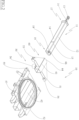
Figure 1 is a perspective view of a retractable drawbar apparatus for a truck trailer in accordance with the present invention; -
Figure 2 is an exploded view of the retractable drawbar apparatus inFigure 1 -
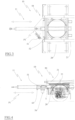
Figure 3 is a plan view of a front part of the truck trailer provided with the retractable drawbar apparatus in accordance with the present invention; -
Figure 4 is a side view of the front part of the trailer inFigure 1 ; -
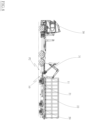
Figures 5-8 are schematic views of the steps of unloading a box from the tractor to the trailer provided with the retractable drawbar apparatus in accordance with the present invention. - With particular reference to these figures, a retractable drawbar apparatus for a truck trailer has been globally referred to as 10.
- The
retractable drawbar apparatus 10 comprises adrawbar 11 comprising arod 12 and aneye 13 integral with one end of the rod; therod 12 preferably has a rectangular cross-section, but even more preferably an octagonal cross-section, with fourequal faces 14 alternating with four otherequal faces 15 and wherein each face orsurface 14 is greater in size than each face orsurface 15. - The
drawbar 11 comprises a protuberance orextension 16 of therod 12 from afront end 17 of therod 12; theextension 16 is smaller in size than therod 12, branches from the central part of theend 17 and has a substantially rectangular cross-section. - The
extension 16 bears theeye 13 which, once theretractable drawbar apparatus 10 is installed in thetrailer 20 of thetruck 30, allows to engage thetrailer 20 with thetruck tractor 30. - The
rod 12 is also provided with aroller 18, preferably arranged at itsend 19, opposite theend 17, to facilitate the sliding of therod 12 in a housing or support 60. - The
retractable drawbar apparatus 10 comprises acarriage 50 which is provided with the housing orsupport 60 of thedrawbar 11. Thecarriage 50 comprises afirst part 51 and asecond part 52, separated from each other; thefirst part 51 is removably connectable to thesecond part 52. Thus, the overall dimensions of the entire apparatus during transport can be reduced. - Preferably the
second part 52 is attachable to thechassis 21 of thetrailer 20 without protruding from thechassis 21, and thefirst part 51 is attachable to thesecond part 52 so as to protrude from thechassis 21 of thetrailer 20, i.e. so as to protrude from the front or rear profile T of thechassis 21 of thetrailer 20. - Preferably, the
first part 51 protrudes longitudinally outside thetrailer 20 once theapparatus 10 is fixed on the trailer and thepart 52 is arranged below the chassis orplatform 21 of thetrailer 20 once theapparatus 10 is fixed on thetrailer 20. - The
part 51 comprises a first part of thehousing 60 of thedrawbar 11; said first part is in the form of ahollow tube 61, preferably with a rectangular cross-section but even more preferably having an octagonal inner cross-section to accommodate theshaft 12. Preferably, thehollow tube 61 comprises near the mouth 64 aroller 63 to facilitate the sliding of therod 12 within thehollow tube 61. -
Part 51 comprises a V-shaped support 53 which is connectable to thesecond part 52, preferably by engaging a pair ofcavities 54, preferably hollow tubes with a circular cross-section and having an axis of symmetry transversal to the sliding direction of therod 12 in thehousing 60, withappropriate pins 55 of thepart 52. -
Part 51 comprises locking means 56 for locking thedrawbar 11 in thehousing 60, in particular inpart 61 of the housing. Preferably said locking means comprise aspring cylinder 56 configured to lock thedrawbar 11 within thehollow tube 61, in particular therear end 19 of therod 12. Thespring cylinder 56 is provided with a piston that engages with a through-hole 66 of therear end 19 of therod 12 to lock thedrawbar 11 in the position of use, i.e. in the position of maximum extension outside thehousing 60. Position of use of thedrawbar 11 refers to the position in which thedrawbar 11 is normally used, i.e. when thetrailer 20 is coupled to thetractor 30, while travelling on the road, and thedrawbar 11 is free to swing. -
Part 52 comprises thesecond part 62 of thehousing 60 of thedrawbar 11; said second part is in the form of ahollow tube 62, preferably having a rectangular cross-section but even more preferably having an octagonal inner cross-section to accommodate theshaft 12. Oncepart 51 is attached topart 52, thehollow tube 62 represents the continuation of thehollow tube 61 along a longitudinal direction. -
Part 52 comprises means 57 for attaching thesame part 52 under the platform orchassis 21 of thetrailer 20. - The
drawbar 11 is longitudinally slidable within thehousing 60 so that thedrawbar 11 can be moved from the position of use P1, which coincides with the position of maximum extension outside the housing orsupport 60, i.e. outside themouth 64 of thehousing 60, into at least one but preferably several non-use positions or retracted positions (for example positions P2 and P3), in which the drawbar is in a retracted position within saidhousing 60 relative to said position of use P1 (visible infigure 5 ), i.e. positions (e.g. position P2 visible inFigure 6 ) in which the drawbar has an extension outside thehousing 60, i.e. outside themouth 64 of thehousing 60, which is lower than the extension of thedrawbar 11 in the position of use P1. A retracted position is also the position in which the drawbar does not protrude outside thehousing 60, i.e. outside themouth 64 of thehousing 60, but is entirely arranged within thehousing 60, such as the position P3 visible inFigure 3 . - Retracted positions are various positions into which the drawbar is moved from its position of use within its
housing 60 manually or by thetractor 30 itself. - In the various retracted positions the
drawbar 11 is idle, i.e. it is not locked within itshousing 60; in the various retracted or non-use positions that thedrawbar 11 may assume, thetruck trailer 20 is stationary, i.e. it is not moving on the road and therefore thedrawbar 11 is not operational. - In the position of use, however, the drawbar is locked in its
housing 60 by means of locking means 56, 66. Specifically, therear end 19 is locked within thehousing 60 by engaging a through-hole 66 of therear end 19 of therod 12 with the piston of thespring cylinder 56. - The
retractable drawbar apparatus 10 is best used to unload abox 22 from thetruck tractor 30 to thetrailer 20. Unloading takes place according to the steps shown inFigures 5-8 . - In the initial step (
Figure 5 ), thetractor 30 provided with thebox 22 is coupled with thetrailer 20, in particular by engaging theeye 13 with an appropriate pin of thetractor 30. In this step, thedrawbar 11 is extended relative to itshousing 60, in particular thedrawbar 11 is in the position of use P1, which coincides with the position of maximum extension outside the housing or support 60. - Once the
drawbar 11 has been disengaged from thehousing 60, after acting on thespring cylinder 56 manually or automatically by moving thetractor 30 towards thetrailer 20, the movement of thetractor 30 towards thetruck trailer 20 allows thedrawbar 11 to be moved within the housing or support 60, i.e. the retraction of thedrawbar 11, to a position P2 which facilitates the unloading of thebox 22 onto thetrailer 20, as visible inFigure 6 . Position P2 is a position of non-use because, even though thedrawbar 11 is engaged with an appropriate pin of thetractor 30, thedrawbar 11 is not operational as thetrailer 20 is stationary in its position. - The
box 22, in particular itsrear end 23, engages with askid 24 sliding longitudinally on the platform orchassis 21 of thetrailer 20. Thechassis 21 normally comprises two sidebars that extend longitudinally and crossbars arranged between the two sidebars. - The
drawbar 11 is idle, i.e. it is not locked, and the retracted position P2 of thesame drawbar 11 is determined by the action of thetractor 30, i.e. the movement of thetractor 30 towards thetrailer 20.Suitable crane equipment 31 allows the complete unloading of thebox 22 from thetractor 30 to thetrailer 20. - The invention thus conceived is susceptible to several modifications and variations, all falling within the scope of the inventive concept.
- Moreover, all the details can be replaced by other technically equivalent elements.
- In practice, the materials used, as well as the contingent shapes and sizes, can be whatever according to the requirements without for this reason departing from the scope of protection of the following claims.
Claims (10)
- Drawbar apparatus (10) for a truck trailer (20), said apparatus comprising:- a drawbar (11),- a housing (60) for said drawbar in which said drawbar slides,- said drawbar being available in a position of use (P1), wherein most of the drawbar is arranged outside said housing, and in at least one position of non-use (P2, P3), wherein the drawbar is in a retracted position inside said housing with respect to said position of use.
- Apparatus according to claim 1, characterised by comprising locking means (56, 66) for locking said drawbar in said housing in the position of use, said drawbar being idle in the at least one position of non-use.
- Apparatus according to claim 1 or 2, characterised by comprising a first part (51) and a second part (52), said first part being removably attachable to said second part.
- Apparatus according to claim 3, characterised in that said second part is attachable to the chassis (21) of the trailer without protruding therefrom and said first part is connectable to said second part so as to protrude from the chassis of the trailer.
- Apparatus according to claim 4, characterised in that said second part is available below the chassis of said trailer and said first part is connectable to said second part so as to protrude longitudinally from the chassis of said trailer.
- Apparatus according to claim 3, characterised in that said housing is divided into a first portion (61) and a second portion (62), said first part of the apparatus comprising said first portion of said housing and said second part of the apparatus comprising said second portion of said housing.
- Apparatus according to claim 2, characterised in that said drawbar comprises an eye (13) and a rod (12), said eye being fixed to the front end (17) of the rod, said locking means (56, 66) being adapted to lock the rear end (19) of said rod, opposite the front end, within said housing in the position of use of the drawbar.
- Apparatus according to claim 7, characterised in that said rod includes a roller (18) for sliding the drawbar into said housing.
- Truck trailer (20) comprising a drawbar apparatus as defined in any one of the preceding claims.
- Trailer (20) according to claim 9, characterised in that said drawbar apparatus is attached to one end of the trailer chassis.
Applications Claiming Priority (1)
| Application Number | Priority Date | Filing Date | Title |
|---|---|---|---|
| IT102023000022749A IT202300022749A1 (en) | 2023-10-30 | 2023-10-30 | RETRACTABLE DRAWBAR APPARATUS FOR TRUCK TRAILER AND RELATED TRAILER |
Publications (1)
| Publication Number | Publication Date |
|---|---|
| EP4549176A1 true EP4549176A1 (en) | 2025-05-07 |
Family
ID=89573647
Family Applications (1)
| Application Number | Title | Priority Date | Filing Date |
|---|---|---|---|
| EP24208718.7A Withdrawn EP4549176A1 (en) | 2023-10-30 | 2024-10-24 | Retractable drawbar device for truck trailer and related trailer |
Country Status (2)
| Country | Link |
|---|---|
| EP (1) | EP4549176A1 (en) |
| IT (1) | IT202300022749A1 (en) |
Citations (3)
| Publication number | Priority date | Publication date | Assignee | Title |
|---|---|---|---|---|
| US20120001403A1 (en) * | 2010-06-30 | 2012-01-05 | John Wydner | Trailer |
| EP2524860B1 (en) * | 2011-05-18 | 2014-06-11 | Stefan Wenner | Fold-down trailer |
| US20210046791A1 (en) * | 2019-08-12 | 2021-02-18 | Reelstrong Utlity Fleet | Integrated Trailer Tongue |
-
2023
- 2023-10-30 IT IT102023000022749A patent/IT202300022749A1/en unknown
-
2024
- 2024-10-24 EP EP24208718.7A patent/EP4549176A1/en not_active Withdrawn
Patent Citations (3)
| Publication number | Priority date | Publication date | Assignee | Title |
|---|---|---|---|---|
| US20120001403A1 (en) * | 2010-06-30 | 2012-01-05 | John Wydner | Trailer |
| EP2524860B1 (en) * | 2011-05-18 | 2014-06-11 | Stefan Wenner | Fold-down trailer |
| US20210046791A1 (en) * | 2019-08-12 | 2021-02-18 | Reelstrong Utlity Fleet | Integrated Trailer Tongue |
Also Published As
| Publication number | Publication date |
|---|---|
| IT202300022749A1 (en) | 2025-04-30 |
Similar Documents
| Publication | Publication Date | Title |
|---|---|---|
| US4473237A (en) | Vehicle lift and tow bar | |
| US4836737A (en) | Wheel lift tow assembly | |
| US5123802A (en) | Motorcycle wheel lift adapter kit | |
| US4679978A (en) | Wheel lift towing assembly | |
| EP0810123B1 (en) | A vehicle crash bar assembly | |
| US11117629B1 (en) | Highway trailer with slide-out undercarriage | |
| US3929237A (en) | Self-storing dolly | |
| US6755433B2 (en) | Transportable storage container assembly | |
| US5762465A (en) | Vehicle lifting and towing method and apparatus | |
| US2374383A (en) | Combination trailer | |
| US5988974A (en) | Vehicle lifting and towing apparatus | |
| CA2844265A1 (en) | Forked vehicle and a method and an assembly for transporting a forked vehicle | |
| WO1999012800A1 (en) | Stowable trailer/dolly system | |
| US2795435A (en) | Vehicle towing device | |
| EP4549176A1 (en) | Retractable drawbar device for truck trailer and related trailer | |
| US4168931A (en) | Freight container transport | |
| US20040081542A1 (en) | Tow bar accessories for towing heavy duty vehicles | |
| US2990194A (en) | Retractable landing gear | |
| US7192007B2 (en) | Jack adapter | |
| US11318802B2 (en) | Hitch assembly for a vehicle | |
| US3837673A (en) | Trailer backable to loading dock from either end | |
| US4033599A (en) | Foldable mudflap assembly | |
| US3417890A (en) | Trailer for towing cars | |
| US5186598A (en) | Retractable arm loading/unloading device and vehicle comprising same | |
| GB2398052A (en) | A-frame towing apparatus |
Legal Events
| Date | Code | Title | Description |
|---|---|---|---|
| PUAI | Public reference made under article 153(3) epc to a published international application that has entered the european phase |
Free format text: ORIGINAL CODE: 0009012 |
|
| STAA | Information on the status of an ep patent application or granted ep patent |
Free format text: STATUS: THE APPLICATION HAS BEEN PUBLISHED |
|
| AK | Designated contracting states |
Kind code of ref document: A1 Designated state(s): AL AT BE BG CH CY CZ DE DK EE ES FI FR GB GR HR HU IE IS IT LI LT LU LV MC ME MK MT NL NO PL PT RO RS SE SI SK SM TR |
|
| STAA | Information on the status of an ep patent application or granted ep patent |
Free format text: STATUS: THE APPLICATION IS DEEMED TO BE WITHDRAWN |
|
| 18D | Application deemed to be withdrawn |
Effective date: 20251108 |