BACKGROUND OF THE INVENTION
TECHNICAL FIELD
-
The present invention relates to a printing apparatus and a printing method.
DESCRIPTION OF RELATED ART
-
In the related art, for the purpose of suppressing a decrease in image quality due to fluff of a textile, an inkjet recording apparatus is known in which the stiffness of the fluff is weakened by applying a liquid to the textile and humidifying the textile, and then the fluff is flattened and compressed by pressurizing the textile (for example, refer to
Japanese Unexamined Patent Publication No. 2020-62847 ).
SUMMARY OF THE INVENTION
-
However, the inkjet recording apparatus disclosed in
Japanese Unexamined Patent Publication No. 2020-62847 adopts a single-pass method and does not consider a multi-pass method in which the textile (medium) is repeatedly conveyed and stopped. Therefore, in a case where an image is formed with a multi-pass method using the inkjet recording apparatus disclosed in the above-mentioned
Japanese Unexamined Patent Publication No. 2020-62847 , there is a problem in that the liquid is excessively applied when the textile is stopped, and printing failure occurs due to insufficient drying after the application of the liquid.
-
The present invention has been made in consideration of the above-described problem, and objects of the present invention include providing a printing apparatus and a printing method that can appropriately perform liquid application, which is performed for the purpose of suppressing fluff of a textile.
-
To achieve at least one of the abovementioned objects, a printing apparatus reflecting an aspect of the present invention comprises: conveyer that conveys a textile; a liquid applier that applies a liquid to the textile; a presser that is disposed downstream of the liquid applier in a textile conveyance direction and presses the textile; a printer that is disposed downstream of the presser in the textile conveyance direction and performs printing on the textile; and a hardware processor that controls the liquid applier such that, when conveyance of the textile by the conveyer is stopped, an amount of the liquid applied to the textile per unit time during the stop of the textile is smaller than the amount of the liquid applied to the textile per unit time during the conveyance of the textile. Advantageous Effects of Invention
-
According to the present invention, it is possible to appropriately perform the liquid application, which is performed for the purpose of suppressing the fluff of the textile.
BRIEF DESCRIPTION OF THE DRAWINGS
-
The advantages and features provided by one or more embodiments of the invention will become more fully understood from the detailed description given hereinbelow and the appended drawings which are given by way of illustration only, and thus are not intended as a definition of the limits of the present invention, wherein:
- FIG. 1 is a schematic diagram schematically illustrating an example of an inkjet textile printing apparatus;
- FIG. 2 is a diagram schematically illustrating an example of a main part of a multi-pass inkjet coating device;
- FIG. 3 is a block diagram illustrating the functional configuration of the textile printing apparatus shown in FIG. 1;
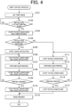
- FIG. 4 is a flowchart illustrating the control procedure of a print control process;
- FIG. 5 is an explanatory diagram of textile edge processing;
- FIG. 6 is an explanatory diagram of the textile edge processing;
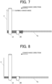
- FIG. 7 is an explanatory diagram of the textile edge processing;
- FIG. 8 is an explanatory diagram of the textile edge processing;
- FIG. 9 is a block diagram illustrating the functional configuration of an inkjet textile printing apparatus according to Modification Example 1;
- FIG. 10 is a flowchart illustrating the control procedure of a print control process executed by the inkjet textile printing apparatus according to Modification Example 1;
- FIG. 11 is an explanatory diagram of textile edge processing executed by the inkjet textile printing apparatus according to Modification Example 1;
- FIG. 12 is an explanatory diagram of the textile edge processing executed by the inkjet textile printing apparatus according to Modification Example 1;
- FIG. 13 is an explanatory diagram of the textile edge processing executed by the inkjet textile printing apparatus according to Modification Example 1;
- FIG. 14 is an explanatory diagram of the textile edge processing executed by the inkjet textile printing apparatus according to Modification Example 1;
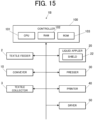
- FIG. 15 is a block diagram illustrating the functional configuration of an inkjet textile printing apparatus according to Modification Example 2;
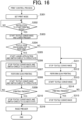
- FIG. 16 is a flowchart illustrating the control procedure of a print control process executed by the inkjet textile printing apparatus according to Modification Example 2;
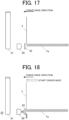
- FIG. 17 is an explanatory diagram of textile edge processing executed by the inkjet textile printing apparatus according to Modification Example 2;
- FIG. 18 is an explanatory diagram of the textile edge processing executed by the inkjet textile printing apparatus according to Modification Example 2;
- FIG. 19 is an explanatory diagram of the textile edge processing executed by the inkjet textile printing apparatus according to Modification Example 2; and
- FIG. 20 is an explanatory diagram of the textile edge processing executed by the inkjet textile printing apparatus according to Modification Example 2.
DETAILED DESCRIPTION
-
Hereinafter, one or more embodiments of the present invention will be described with reference to the drawings. However, the scope of the invention is not limited to the disclosed embodiments.
[Configuration of Inkjet Textile Printing Apparatus]
-
FIG. 1 is a schematic view schematically illustrating an example of an inkjet textile printing apparatus (printing apparatus) according to the present invention.
-
As illustrated in FIG. 1, the inkjet textile printing apparatus (hereinafter, also simply referred to as the "textile printing apparatus") 1 includes a textile feeder 2, a textile collector 3, a conveyer 10, a liquid applier 20, a presser 30, a printer 40, a dryer 50, a controller (hardware processor) 100 that controls each member, and the like.
-
In FIG. 1, a conveyance direction of a textile T is indicated by an arrow. The textile printing apparatus 1 may include other constituent members than the constituent members illustrated in FIG. 1, if necessary. The other constituent members include, for example, a fixing section (not illustrated) disposed downstream of the dryer 50 in the conveyance direction.
-
Hereinafter, each constituent member of the textile printing apparatus 1 will be described.
<Fabric Feeder>
-
The textile T is installed in the textile feeder 2 disposed on the upstream side of the liquid applier 20 in the conveyance direction. The textile feeder 2 includes a rotating shaft on which the roll-shaped textile T is mounted, and a motor (not illustrated) that rotationally drives the rotating shaft in a predetermined rotation direction. The textile feeder 2 feeds the textile T to the downstream side in the conveyance direction with the rotation of the rotating shaft by driving the motor.
<Conveyer>
-
The conveyer 10 includes a conveyance roller (not illustrated), a belt conveyer (not illustrated), and the like, and conveys the textile T fed from the textile feeder 2.
<Liquid Applier>
-
The liquid applier 20 humidifies the edge Te of the textile T by spraying and applying liquid (for example, ordinary tap water) to the edge Te (refer to FIG. 2) along the conveyance direction of the textile T being conveyed by the conveyer 10. The liquid applier 20 is capable of adjusting the amount of liquid applied to the textile T per unit time under the control of the controller 100. The humidification of the edge Te of the textile T by the liquid applier 20 can weaken the stiffness of fluff generated at the edge Te of the textile T.
-
The specific configuration of the liquid applier 20 is not particularly limited, but a configuration may be used in which a minute water supply nozzle to spray a liquid is included, and the liquid is supplied to the water supply nozzle at a predetermined water pressure via a water supply tube. As a mechanism for adjusting the amount of liquid applied to the textile T, a mechanism for changing the pressure of liquid supplied to a water supply nozzle can be used, for example.
<Presser>
-
The presser 30 includes a pair of pressing rollers 31 and a roller lifting unit (not illustrated). The presser 30 presses the textile T by sandwiching the textile T between the pair of pressing rollers 31. One of the pair of pressing rollers 31 (here, the upper roller) is movably disposed in the vertical direction in FIG. 1, and the pressure applied to the textile T can be adjusted in accordance with the movement in the vertical direction. The movement of the pressing roller 31 in the vertical direction is performed by the above-described roller lifting unit under the control of the controller 100.
-
A cylindrical roller heater (not shown) extending along the rotation shaft is disposed in the upper roller of the pair of rollers constituting the pressing rollers 31. A heating medium such as high-temperature steam or hot water passes through the inside of the roller heater, and the heat of the heating medium is transmitted to the outer peripheral surface of the roller to heat the outer peripheral surface. The pressing roller 31 heats the textile T to a predetermined temperature by transmitting the heat of the outer peripheral surface to the textile T. The pressing roller 31 is provided so as to be capable of adjusting the heating temperature of the textile T. Specifically, as the temperature and flow rate of the heating medium flowing through the roller heater are changed under the control of the controller 100, the heating temperature of the textile T by the pressing roller 31 is adjusted. As described above, the pressing rollers 31 sandwich the textile T to apply pressure and heat to the textile T, thereby flattening and compressing the fluff generated at the edge Te of the textile T and removing wrinkle and the like of the textile T. As a result, when printing on the textile T is performed by the printer 40 described later, it is possible to prevent the fluff generated at the edge Te of the textile T from contacting and damaging the nozzle.
<Printer>
-
The printer 40 is a multi-pass inkjet coating device that performs a process of coating the textile T with a treatment liquid Pr and an ink In.
-
FIG. 2 is a diagram schematically illustrating an example of a main part of the multi-pass inkjet coating device.
-
As shown in FIG. 2, a droplet ejecting unit 41 of the inkjet coating device moves in a scanning direction X (hereinafter, also referred to as an "X direction") on the textile T while ejecting the ink In of each color (yellow ink Y, magenta ink M, cyan ink C, and black ink K) and the treatment liquid Pr, thereby forming an image. The textile T is sequentially conveyed in a direction Y (hereinafter, also referred to as a "conveyance direction Y" or a "Y direction") orthogonal to the scanning direction X by a conveying unit (not illustrated), and thus an image can be formed on substantially the entire surface (image forming surface) of the textile T.
-
The droplet ejecting unit 41 includes a treatment liquid head 42Pr, an yellow ink head 42Y, a magenta ink head 42M, a cyan ink head 42C, and a black ink head 42K (hereinafter, collectively referred to as a "head unit 42"), and a carriage 43 for arranging and holding the head unit 42 along the scanning direction X.
-
That is, the treatment liquid head 42Pr and the ink heads 42Y, 42M, 42C, and 42K are mounted on the same carriage 43.
-
On a face of each head facing the surface of the textile T, a plurality of nozzles (not illustrated) are arranged along the conveyance direction Y orthogonal to the scanning direction X, and when appropriate pressure is applied to the ink In and the treatment liquid Pr, minute liquid droplets are ejected from the nozzles. The droplet ejecting units 41 is supported in a state where the nozzle faces of the head unit 42 are separated from the surface of the textile T by a predetermined distance in a direction orthogonal to the surface (height direction).
-
The droplet ejecting unit 41 is scanned in the scanning direction X by a scanning section 44. The scanning section 44 includes, for example, a rail that supports the carriage 43 in a state in which the nozzle faces are separated from the surface of the textile T by the above-described predetermined distance in the height direction, and allows the carriage 43 to move along the rail extending along the scanning direction X.
-
An operation of applying the ink In and the treatment liquid Pr to the textile T by one movement of the liquid droplet ejecting unit 41 in the scanning direction X is defined as one printing pass. In the multi-pass coating method as shown in FIG. 2, a plurality of printing passes are performed on the same region. Thus, a desired image is formed on the textile T.
<Dryer>
-
The dryer 50 dries the treatment liquid Pr and the ink In applied by the printer 40. The drying means is not particularly limited, but heating with warm air, a hot plate, or a heat roller is preferable.
<Fabric Collector>
-
The textile collector 3 is disposed downstream of the dryer 50, and collects the textile (printed textile) T, on which the treatment liquid Pr and the ink In have been dried by the dryer 50, with winding up the textile T.
<Controller>
-
FIG. 3 is a block diagram illustrating the functional configuration of the textile printing apparatus 1 shown in FIG. 1.
-
As shown in FIG. 3, the controller 100 integrally controls the entire operation of the textile printing apparatus 1. Alternatively, the textile feeder 2, the textile collector 3, the conveyer 10, the liquid applier 20, the presser 30, the printer 40, and the dryer 50 may include respective controllers that are connected to each other so that the constituent members of the textile printing apparatus 1 operate in conjunction with each other. The controller 100 includes a central processing unit (CPU) 101, a random-access memory (RAM) 102, a read only memory (ROM) 103, and the like.
-
The CPU 101 reads various control programs and setting data stored in the ROM 103, stores the read programs and data in the RAM 102, and executes the programs to carry out various calculation processes. Also, the CPU 101 comprehensively controls the overall operation of the textile printing apparatus 1.
-
The RAM 102 provides a working memory space for the CPU 101 and stores temporary data. The RAM 102 may include a non-volatile memory.
-
The ROM 103 stores various control programs to be executed by the CPU 101, setting data, and the like. Note that a rewritable nonvolatile memory such as a flash memory may be used instead of the ROM 103.
[Operation of Inkjet Textile Printing Apparatus]
-
Next, the operation of the textile printing apparatus 1 will be described. Specifically, a printing operation performed by the textile printing apparatus 1 will be described with reference to FIG. 4. The CPU 101 of the textile printing apparatus 1 executes a print control process in order to achieve the printing operation.
-
FIG. 4 is a flowchart illustrating the control procedure of the print control process.
-
As illustrated in FIG. 4, when the print control process is started, first, the CPU 101 of the textile printing apparatus 1 sets the print mode based on a user operation (step S101). In this step, as shown in FIG. 5, the user sets the textile T in the textile printing apparatus 1 so that the leading edge of the textile T on which printing is performed is disposed at a predetermined position on the upstream side of the liquid applier 20 in the conveyance direction. In FIGS. 5 to 8, the edge Te on one side along the conveyance direction of the textile T is illustrated, and the edge Te on the other side and the liquid applier 20 that applies the liquid to the edge Te on the other side are not illustrated. It is assumed that the setting of the print mode includes the setting of whether to perform textile edge processing. The textile edge processing means processing of spraying a liquid to the edge Te along the conveyance direction of the textile T by the liquid applier 20.
-
Next, the CPU 101 determines whether an instruction to start printing has been given (step S102).
-
When it is determined in step S102 that the instruction to start printing has not been given (step S102; NO), the CPU 101 repeatedly performs the determination process of step S102 until the instruction to start printing is given.
-
In step S102, when it is determined that the instruction to start printing has been given (step S102; YES), the CPU 101 causes the conveyer 10 to start conveying the textile T as shown in FIG. 6 (step S103). Further, the CPU 101 lowers one roller (here, the upper roller) of the pair of pressing rollers 31 of the presser 30 by the roller lifting unit (step S 103). A circled X in the drawing indicates that the upper pressing roller 31 has been lowered.
-
Next, the CPU 101 determines whether the setting for performing the textile edge processing has been made (step S104).
-
In step S104, when it is determined that the setting for performing the textile edge processing has been made (step S104; YES), the CPU 101 causes the liquid applier 20 to start applying the liquid to the edge Te of the textile T as illustrated in FIG. 6 (step S105). In this manner, as shown in FIG. 7, the edge Te of the textile T is humidified by the liquid applier 20 while the textile T is being conveyed by the conveyer 10. In addition, the textile T whose edge Te has been humidified by the liquid applier 20 is nipped by the presser 30 on the downstream side in the conveyance direction to be pressurized and heated. Thus, the fluff generated at the edge Te of the textile T is flattened and compressed, and the wrinkle and the like of the textile T are removed.
-
Next, when the textile T is conveyed to a position where scan printing (multi-pass printing) is performed by the printer 40, as shown in FIG. 8, the CPU 101 stops the conveyance of the textile T by the conveyer 10 (step S106). Furthermore, the CPU 101 causes the liquid applier 20 to stop applying the liquid to the edge Te of the textile T (step S106).
-
Next, the CPU 101 executes scan printing for one scan by the printer 40 (step S107).
-
Next, when the scan printing for one scan is completed, the CPU 101 causes the conveyer 10 to start conveyance of the textile T and also causes the liquid applier 20 to start application of the liquid to the edge Te of the textile T, as illustrated in FIG. 7 (step S108).
-
Next, the CPU 101 determines whether printing in the print mode set in step S101 has been completed (step S109).
-
When it is determined in step S109 that the printing in the print mode set in step S101 has not been completed (NO in step S109), the CPU 101 returns the process to step S106, and repeats the subsequent processes.
-
In addition, in step S109, when it is determined that the printing in the print mode set in step S101 has been completed (step S109; YES), the CPU 101 stops the conveyance of the textile T by the conveyer 10 as illustrated in FIG. 8 (step S110). Furthermore, the CPU 101 causes the liquid applier 20 to stop applying the liquid to the edge Te of the textile T (step S110).
-
Next, the CPU 101 raises one roller (here, the upper roller) of the pair of pressing rollers 31 of the presser 30 by the roller lifting unit (step S116). Then, the CPU 101 ends the print control process.
-
In addition, in step S104, when it is determined that the setting for performing the textile edge processing has not been made (step S104; NO), the CPU 101 stops the conveyance of the textile T by the conveyer 10 when the textile T is conveyed to a predetermined position (step S111). The predetermined position is a position where scan printing (multi-pass printing) by the printer 40 is performed.
-
Next, the CPU 101 executes scan printing for one scan by the printer 40 (step S112).
-
Next, when the scan printing for one scan is finished, the CPU 101 causes the conveyer 10 to start conveying the textile T (step S113).
-
Next, the CPU 101 determines whether printing in the print mode set in step S101 has been completed (step S114).
-
When it is determined in step S114 that the printing in the print mode set in step S101 has not been completed (NO in step S114), the CPU 101 returns the process to step S111, and repeats the subsequent processes.
-
When it is determined in step S114 that the printing in the print mode set in step S101 has been completed (step S114; YES), the CPU 101 stops the conveyance of the textile T by the conveyer 10 (step S115).
-
Next, the CPU 101 raises one roller (here, the upper roller) of the pair of pressing rollers 31 of the presser 30 by the roller lifting unit (step S116). Then, the CPU 101 ends the print control process.
-
As described above, the textile printing apparatus 1 includes the conveyer 10 that conveys the textile T. The textile printing apparatus 1 includes the liquid applier 20 that applies the liquid to the textile T. The textile printing apparatus 1 includes the presser 30 which is disposed downstream of the liquid applier 20 in the textile conveyance direction and presses the textile T.
-
The textile printing apparatus 1 includes the printer 40 that is disposed downstream of the presser 30 in the textile conveyance direction and performs printing on the textile T. The textile printing apparatus 1 includes the controller 100 that, when the conveyance of the textile T by the conveyer 10 is stopped, controls the liquid applier 20 such that the amount of liquid applied to the textile T (per unit time) during the stop of the textile T is smaller than that during the conveyance of the textile T.
-
Therefore, according to the textile printing apparatus 1, when the conveyance of the textile T by the conveyer 10 is stopped, the liquid applier 20 is controlled such that the amount of liquid applied to the textile T (per unit time) is smaller than that during the conveyance of the textile T. This makes it possible to appropriately perform the liquid application, which is performed for the purpose of suppressing the fluff of the textile T. This prevents the liquid from being excessively applied when the textile T is stopped, thereby preventing a printing failure from occurring due to insufficient drying after the application of the liquid.
-
The printer 40 of the textile printing apparatus 1 is scannable in a direction intersecting the textile conveyance direction. The controller 100 causes the conveyer 10 to repeatedly convey and stop the textile T, causes the printer 40 to perform printing on the textile T during the stop of the textile T, and controls the liquid applier 20 such that the amount of liquid applied to the textile T (per unit time) during the stop is smaller than that during the conveyance of the textile T.
-
Therefore, according to the textile printing apparatus 1, when the printer 40 is operated to perform printing on the textile T (multi-pass printing), the liquid applier 20 is controlled such that the amount of liquid applied to the textile T (per unit time) is smaller than that during conveyance of the textile T. This makes it possible to appropriately perform the liquid application, which is performed for the purpose of suppressing the fluff of the textile T. This prevents the liquid from being excessively applied when the textile T is stopped, thereby preventing a printing failure from occurring due to insufficient drying after the application of the liquid.
-
In addition, the controller 100 of the textile printing apparatus 1 controls the liquid applier 20 such that the liquid applier 20 applies the liquid during the conveyance of the textile T by the conveyer 10 and stops applying the liquid during the stop of the textile T. Therefore, according to the textile printing apparatus 1, it is possible to more appropriately perform the liquid application, which is performed for the purpose of suppressing the fluff of the textile T. This prevents the liquid from being excessively applied when the textile T is stopped, thereby more efficiently preventing a printing failure from occurring due to insufficient drying after the application of the liquid.
-
In addition, the liquid applier 20 of the textile printing apparatus 1 applies the liquid to the edge Te of the textile T along the textile conveyance direction. Therefore, according to the textile printing apparatus 1, it is possible to cope with an inexpensive textile that often has fluff at the edge of the textile. This makes it possible to appropriately perform printing on various types of textile.
-
The liquid applier 20 of the textile printing apparatus 1 applies the liquid to the textile T by spraying the liquid. Therefore, according to the textile printing apparatus 1, it is possible to easily permeate the liquid into the fluff of the textile T by spraying the liquid. This makes it possible to effectively weaken the stiffness of the fluff.
-
The liquid applier 20 of the textile printing apparatus 1 applies ordinary tap water as the liquid. Therefore, according to the textile printing apparatus 1, it is possible to suppress the cost for applying the liquid to the textile T.
[Modification Example 1]
-
Next, a textile printing apparatus 1A according to Modification Example 1 will be described. Note that the same constituent elements as those in the above-described embodiment are denoted by the same reference numerals, and description thereof will be omitted.
-
FIG. 9 is a block diagram illustrating the functional configuration of the textile printing apparatus 1A according to Modification Example 1. The textile printing apparatus 1A is characterized by including a movable unit 21 in the liquid applier 20. The movable unit 21 is a mechanism that moves the liquid applier 20 between a retracted position (see FIG. 11) at which the liquid applier 20 does not apply the liquid to the edge Te of the textile T and an application position (see FIG. 13) at which the liquid applier 20 is capable of applying the liquid to the edge Te of the textile T.
-
Next, the operation of the textile printing apparatus 1A will be described. Specifically, a printing operation performed by the textile printing apparatus 1A will be described with reference to FIG. 10. The CPU 101 of the textile printing apparatus 1A executes a print control process in order to achieve the printing operation.
-
FIG. 10 is a flowchart illustrating the control procedure of the print control process executed by the textile printing apparatus 1A.
-
As illustrated in FIG. 10, when the print control process is started, first, the CPU 101 of the textile printing apparatus 1A sets the print mode based on a user operation (step S201). In this step, as shown in FIG. 11, the user sets the textile T in the textile printing apparatus 1A so that the leading edge of the textile T on which printing is performed is disposed at a predetermined position on the upstream side of the liquid applier 20 in the conveyance direction. In addition, in this step, the liquid applier 20 is disposed at the retracted position at which the liquid applier 20 does not apply the liquid to the edge Te of the textile T. In FIGS. 11 to 14, the edge Te on one side along the conveyance direction of the textile T is illustrated, and the edge Te on the other side and the liquid applier 20 that applies the liquid to the edge Te on the other side are not illustrated. It is assumed that the setting of the print mode includes the setting of whether to perform textile edge processing.
-
Next, the CPU 101 determines whether an instruction to start printing has been given (step S202).
-
When it is determined in step S202 that the instruction to start printing has not been given (step S202; NO), the CPU 101 repeatedly performs the determination process of step S202 until the instruction to start printing is given.
-
In step S202, when it is determined that the instruction to start printing has been given (step S202; YES), the CPU 101 causes the conveyer 10 to start conveying the textile T as shown in FIG. 12 (step S203). Further, the CPU 101 lowers one roller (here, the upper roller) of the pair of pressing rollers 31 of the presser 30 by the roller lifting unit (step S203). A circled X in the drawing indicates that the upper pressing roller 31 has been lowered.
-
Next, the CPU 101 determines whether the setting for performing the textile edge processing has been made (step S204).
-
In step S204, when it is determined that the setting for performing the textile edge processing has been made (step S204; YES), the CPU 101 causes the liquid applier 20 to start applying the liquid as illustrated in FIG. 12. Then, when the application of the liquid is stabilized, the CPU 101 moves the liquid applier 20 to the application position where the liquid applier 20 is capable of applying the liquid to the edge Te of the textile T (step S205). In this manner, as shown in FIG. 13, the edge Te of the textile T is humidified by the liquid applier 20 while the textile T is being conveyed by the conveyer 10. In addition, the textile T whose edge Te has been humidified by the liquid applier 20 is nipped by the presser 30 on the downstream side in the conveyance direction to be pressurized and heated. Thus, the fluff generated at the edge Te of the textile T is flattened and compressed, and the wrinkle and the like of the textile T are removed.
-
Next, when the textile T is conveyed to a position where scan printing (multi-pass printing) is performed by the printer 40, as shown in FIG. 14, the CPU 101 stops the conveyance of the textile T by the conveyer 10 (step S206). The CPU 101 also moves the liquid applier 20 to the retracted position where no liquid is applied to the edge Te of the textile T (step S206).
-
Next, the CPU 101 executes scan printing for one scan by the printer 40 (step S207).
-
Next, when the scan printing for one scan is completed, the CPU 101 causes the conveyer 10 to start conveyance of the textile T, and moves the liquid applier 20 to the application position, as illustrated in FIG. 12 (step S208).
-
Next, the CPU 101 determines whether printing in the print mode set in step S201 has been completed (step S209).
-
When it is determined in step S209 that the printing in the print mode set in step S201 has not been completed (NO in step S209), the CPU 101 returns the process to step S206, and repeats the subsequent processes.
-
In addition, in step S209, when it is determined that the printing in the print mode set in step S201 has been completed (step S209; YES), the CPU 101 stops the conveyance of the textile T by the conveyer 10 as illustrated in FIG. 14 (step S210). In addition, the CPU 101 moves the liquid applier 20 to the retracted position (step S210).
-
Next, the CPU 101 raises one roller (here, the upper roller) of the pair of pressing rollers 31 of the presser 30 by the roller lifting unit (step S216). Then, the CPU 101 ends the print control process.
-
In addition, in step S204, when it is determined that the setting for performing the textile edge processing has not been made (step S204; NO), the CPU 101 stops the conveyance of the textile T by the conveyer 10 when the textile T is conveyed to a predetermined position (step S211). The predetermined position is a position where scan printing (multi-pass printing) by the printer 40 is performed.
-
Next, the CPU 101 executes scan printing for one scan by the printer 40 (step S212).
-
Next, when the scan printing for one scan is finished, the CPU 101 causes the conveyer 10 to start conveying the textile T (step S213).
-
Next, the CPU 101 determines whether printing in the print mode set in step S201 has been completed (step S214).
-
When it is determined in step S214 that the printing in the print mode set in step S201 has not been completed (NO in step S214), the CPU 101 returns the process to step S211, and repeats the subsequent processes.
-
When it is determined in step S214 that the printing in the print mode set in step S201 has been completed (step S214; YES), CPU 101 stops the conveyance of the textile T by the conveyer 10 (step S215).
-
Next, the CPU 101 raises one roller (here, the upper roller) of the pair of pressing rollers 31 of the presser 30 by the roller lifting unit (step S216). Then, the CPU 101 ends the print control process.
-
As described above, the liquid applier 20 of the textile printing apparatus 1A is movable between the application position at which the liquid applier 20 is capable of applying the liquid to the textile T and the retracted position at which the liquid applier 20 does not apply the liquid to the textile T under the control of the controller 100. The controller 100 controls the liquid applier 20 such that the liquid applier 20 is located at the application position during the conveyance of the textile T by the conveyer 10 and is located at the retracted position during the stop of the textile T. Therefore, according to the textile printing apparatus 1A, it is possible to appropriately perform the liquid application, which is performed for the purpose of suppressing the fluff of the textile T. This prevents the liquid from being excessively applied when the textile T is stopped, thereby efficiently preventing a printing failure from occurring due to insufficient drying after the application of the liquid.
[Modification Example 2]
-
Next, a textile printing apparatus 1B according to Modification Example 2 will be described. Note that the same constituent elements as those in the above-described embodiment are denoted by the same reference numerals, and description thereof will be omitted.
-
FIG. 15 is a block diagram illustrating the functional configuration of the textile printing apparatus 1B according to Modification Example 2. The textile printing apparatus 1B is characterized by including a shield 22 in the liquid applier 20. Under the control of the controller 100, the state of the shield 22 can be switched to a closed state (first state) (see FIG. 17) for blocking the application of the liquid to the edge Te of the textile T. In addition, the state of the shield 22 can be switched to an open state (second state) (see FIG. 19) for releasing the blocking described above to allow for the application of the liquid to the edge Te of the textile T under the control of the controller 100.
-
Next, the operation of the textile printing apparatus 1B will be described. Specifically, a printing operation performed by the textile printing apparatus 1B will be described with reference to FIG. 16. The CPU 101 of the textile printing apparatus 1B executes a print control process in order to achieve the printing operation.
-
FIG. 16 is a flowchart illustrating the control procedure of the print control process executed by the textile printing apparatus 1B.
-
As illustrated in FIG. 16, when the print control process is started, first, the CPU 101 of the textile printing apparatus 1B sets the print mode based on a user operation (step S301). In this step, as shown in FIG. 17, the user sets the textile T in the textile printing apparatus 1B so that the leading edge of the textile T on which printing is performed is disposed at a predetermined position on the upstream side of the liquid applier 20 in the conveyance direction. Furthermore, in this step, the state of the shield 22 is switched to the closed state (the first state) for blocking the application of the liquid to the edge Te of the textile T. In FIGS. 17 to 20, the edge Te on one side along the conveyance direction of the textile T is illustrated, and the edge Te on the other side, and the liquid applier 20 that applies the liquid to the edge Te on the other side and the shield 22 are not illustrated. It is assumed that the setting of the print mode includes the setting of whether to perform textile edge processing.
-
Next, the CPU 101 determines whether an instruction to start printing has been given (step S302).
-
When it is determined in step S302 that the instruction to start printing has not been given (step S302; NO), the CPU 101 repeatedly performs the determination process of step S302 until the instruction to start printing is given.
-
In step S302, when it is determined that the instruction to start printing has been given (step S302; YES), the CPU 101 causes the conveyer 10 to start conveying the textile T as shown in FIG. 18 (step S303). Further, the CPU 101 lowers one roller (here, the upper roller) of the pair of pressing rollers 31 of the presser 30 by the roller lifting unit (step S303). A circled X in the drawing indicates that the upper pressing roller 31 has been lowered.
-
Next, the CPU 101 determines whether the setting for performing the textile edge processing has been made (step S304).
-
In step S304, when it is determined that the setting for performing the textile edge processing has been made (step S304; YES), CPU 101 causes the liquid applier 20 to start applying the liquid as illustrated in FIG. 18. Next, when the application of the liquid is stabilized, the state of the shield 22 is switched from the above-described closed state to the open state (the second state) in which the liquid can be applied to the edge Te of the textile T (step S305). In this manner, as shown in FIG. 19, the edge Te of the textile T is humidified by the liquid applier 20 while the textile T is being conveyed by the conveyer 10. In addition, the textile T whose edge Te has been humidified by the liquid applier 20 is nipped by the presser 30 on the downstream side in the conveyance direction to be pressurized and heated. Thus, the fluff generated at the edge Te of the textile T is flattened and compressed, and the wrinkle and the like of the textile T are removed.
-
Next, when the textile T is conveyed to a position where scan printing (multi-pass printing) is performed by the printer 40, as shown in FIG. 20, the CPU 101 stops the conveyance of the textile T by the conveyer 10 (step S306). Further, the CPU 101 switches the state of the shield 22 to the closed state (step S306).
-
Next, the CPU 101 executes scan printing for one scan by the printer 40 (step S307).
-
Next, when the scan printing for one scan is completed, the CPU 101 causes the conveyer 10 to start conveyance of the textile T and switches the state of the shield 22 to the open state, as illustrated in FIG. 18 (step S308).
-
Next, the CPU 101 determines whether printing in the print mode set in step S301 has been completed (step S309).
-
When it is determined in step S309 that the printing in the print mode set in step S301 has not been completed (NO in step S309), the CPU 101 returns the process to step S306, and repeats the subsequent processes.
-
In addition, in step S309, when it is determined that the printing in the print mode set in step S301 has been completed (step S309; YES), the CPU 101 stops the conveyance of the textile T by the conveyer 10 as illustrated in FIG. 20 (step S310). Further, the CPU 101 switches the state of the shield 22 to the closed state (step S310).
-
Next, the CPU 101 raises one roller (here, the upper roller) of the pair of pressing rollers 31 of the presser 30 by the roller lifting unit (step S316). Then, the CPU 101 ends the print control process.
-
In addition, in step S304, when it is determined that the setting for performing the textile edge processing has not been made (step S304; NO), the CPU 101 stops the conveyance of the textile T by the conveyer 10 when the textile T is conveyed to a predetermined position (step S311). The predetermined position is a position where scan printing (multi-pass printing) by the printer 40 is performed.
-
Next, the CPU 101 executes scan printing for one scan by the printer 40 (step S312).
-
Next, when the scan printing for one scan is finished, the CPU 101 causes the conveyer 10 to start conveying the textile T (step S313).
-
Next, the CPU 101 determines whether printing in the print mode set in step S301 has been completed (step S314).
-
When it is determined in step S314 that the printing in the print mode set in step S301 has not been completed (NO in step S314), the CPU 101 returns the process to step S311, and repeats the subsequent processes.
-
When it is determined in step S314 that the printing in the print mode set in step S301 has been completed (step S314; YES), CPU 101 stops the conveyance of the textile T by the conveyer 10 (step S315).
-
Next, the CPU 101 raises one roller (here, the upper roller) of the pair of pressing rollers 31 of the presser 30 by the roller lifting unit (step S316). Then, the CPU 101 ends the print control process.
-
As described above, the textile printing apparatus 1B includes the shield 22 that blocks the application of the liquid to the textile T. The controller 100 switches the state of the shield 22 between the closed state (first state) for blocking the application of the liquid to the textile T and the open state (second state) for releasing the blocking to allow for the application of the liquid to the textile T. Therefore, according to the textile printing apparatus 1B, including the shield 22 makes it possible to appropriately perform the liquid application, which is performed for the purpose of suppressing the fluff of the textile. This prevents the liquid from being excessively applied to the textile T, thereby preventing a printing failure from occurring due to insufficient drying after the application of the liquid.
-
In addition, the controller 100 of the textile printing apparatus 1B switches the state of the shield 22 to the open state (second state) during the conveyance of the textile T by the conveyer 10, and switches the state of the shield 22 to the closed state (first state) during the stop of the textile T. Therefore, according to the textile printing apparatus 1B, it is possible to more appropriately perform the liquid application, which is performed for the purpose of suppressing the fluff of the textile T. This prevents the liquid from being excessively applied when the textile T is stopped, thereby more efficiently preventing a printing failure from occurring due to insufficient drying after the application of the liquid.
-
Note that the description in the above embodiment, Modification Example 1, and Modification Example 2 is an example of the printing apparatus and printing method according to the present invention, and the present invention is not limited thereto.
-
For example, although the liquid applier 20 is controlled to stop applying the liquid when the conveyance of the textile T by the conveyer 10 is stopped in the embodiment described above, such control is merely an example. For example, the liquid applier 20 may be controlled such that a small amount of liquid (per unit time) is applied as compared with that during the conveyance of the textile T by the conveyer 10, without completely stopping the application of the liquid during the stop of the textile T. Furthermore, in such a case, the liquid applier 20 may be controlled to reduce the amount of liquid applied (per unit time) in accordance with the time length of printing performed by the printer 40 during the stop of the conveyance of the textile T by the conveyer 10.
-
Furthermore, in the above embodiment, Modification Example 1, and Modification Example 2, an absorber (e.g., an absorbing roller) that, when the textile T is pressed by the presser 30, absorbs the liquid attached to the presser 30 may be provided. This makes it possible to prevent the liquid from being excessively applied to the edge Te of the textile T, and also to prevent the liquid from being applied to a region other than the edge Te of the textile T.
-
In addition, in the above embodiment, Modification Example 1, and Modification Example 2, the controller 100 may adjust the amount of the liquid applied per unit time by the liquid applier 20 according to the conveyance speed of the conveyer 10.
-
In addition, in the above embodiment, Modification Example 1, and Modification Example 2, the ordinary tap water is mentioned as an example of the liquid applied by the liquid applier 20, but for example, a liquid having a higher viscosity than the ordinary tap water, such as a surfactant aqueous solution, may be applied.
-
In addition, in the above embodiment, Modification Example 1, and Modification Example 2, the textile printing apparatuses 1, 1A, and 1B adopting the multi-pass method have been described as application examples of the printing apparatus of the present invention, but the present invention can also be applied to a single-pass inkjet textile printing apparatus.
-
In addition, it is a matter of course that the detailed configuration and the detailed operation of each constituent element of the
textile printing apparatuses 1, 1A, and 1B in the above embodiment, Modification Example 1, and Modification Example 2 can be appropriately changed without departing from the spirit of the present invention. Although embodiments of the present invention have been described and illustrated in detail, the disclosed embodiments are made for purposes of illustration and example only and not limitation. The scope of the present invention should be interpreted by terms of the appended claims.
The entire disclosure of
Japanese Patent Application No. 2023-186529 filed on October 31, 2023 , is incorporated herein by reference in its entirety.