EP4549136A1 - Compression resin transfer infusion methods - Google Patents
Compression resin transfer infusion methods Download PDFInfo
- Publication number
- EP4549136A1 EP4549136A1 EP24202480.0A EP24202480A EP4549136A1 EP 4549136 A1 EP4549136 A1 EP 4549136A1 EP 24202480 A EP24202480 A EP 24202480A EP 4549136 A1 EP4549136 A1 EP 4549136A1
- Authority
- EP
- European Patent Office
- Prior art keywords
- infusion
- temperature
- resin
- curing
- cure tool
- Prior art date
- Legal status (The legal status is an assumption and is not a legal conclusion. Google has not performed a legal analysis and makes no representation as to the accuracy of the status listed.)
- Pending
Links
Images




Classifications
-
- B—PERFORMING OPERATIONS; TRANSPORTING
- B29—WORKING OF PLASTICS; WORKING OF SUBSTANCES IN A PLASTIC STATE IN GENERAL
- B29C—SHAPING OR JOINING OF PLASTICS; SHAPING OF MATERIAL IN A PLASTIC STATE, NOT OTHERWISE PROVIDED FOR; AFTER-TREATMENT OF THE SHAPED PRODUCTS, e.g. REPAIRING
- B29C70/00—Shaping composites, i.e. plastics material comprising reinforcements, fillers or preformed parts, e.g. inserts
- B29C70/04—Shaping composites, i.e. plastics material comprising reinforcements, fillers or preformed parts, e.g. inserts comprising reinforcements only, e.g. self-reinforcing plastics
- B29C70/28—Shaping operations therefor
- B29C70/40—Shaping or impregnating by compression not applied
- B29C70/42—Shaping or impregnating by compression not applied for producing articles of definite length, i.e. discrete articles
- B29C70/46—Shaping or impregnating by compression not applied for producing articles of definite length, i.e. discrete articles using matched moulds, e.g. for deforming sheet moulding compounds [SMC] or prepregs
- B29C70/467—Shaping or impregnating by compression not applied for producing articles of definite length, i.e. discrete articles using matched moulds, e.g. for deforming sheet moulding compounds [SMC] or prepregs and impregnating the reinforcements during mould closing
-
- B—PERFORMING OPERATIONS; TRANSPORTING
- B29—WORKING OF PLASTICS; WORKING OF SUBSTANCES IN A PLASTIC STATE IN GENERAL
- B29C—SHAPING OR JOINING OF PLASTICS; SHAPING OF MATERIAL IN A PLASTIC STATE, NOT OTHERWISE PROVIDED FOR; AFTER-TREATMENT OF THE SHAPED PRODUCTS, e.g. REPAIRING
- B29C70/00—Shaping composites, i.e. plastics material comprising reinforcements, fillers or preformed parts, e.g. inserts
- B29C70/04—Shaping composites, i.e. plastics material comprising reinforcements, fillers or preformed parts, e.g. inserts comprising reinforcements only, e.g. self-reinforcing plastics
- B29C70/28—Shaping operations therefor
- B29C70/40—Shaping or impregnating by compression not applied
- B29C70/42—Shaping or impregnating by compression not applied for producing articles of definite length, i.e. discrete articles
- B29C70/46—Shaping or impregnating by compression not applied for producing articles of definite length, i.e. discrete articles using matched moulds, e.g. for deforming sheet moulding compounds [SMC] or prepregs
- B29C70/48—Shaping or impregnating by compression not applied for producing articles of definite length, i.e. discrete articles using matched moulds, e.g. for deforming sheet moulding compounds [SMC] or prepregs and impregnating the reinforcements in the closed mould, e.g. resin transfer moulding [RTM], e.g. by vacuum
-
- B—PERFORMING OPERATIONS; TRANSPORTING
- B29—WORKING OF PLASTICS; WORKING OF SUBSTANCES IN A PLASTIC STATE IN GENERAL
- B29C—SHAPING OR JOINING OF PLASTICS; SHAPING OF MATERIAL IN A PLASTIC STATE, NOT OTHERWISE PROVIDED FOR; AFTER-TREATMENT OF THE SHAPED PRODUCTS, e.g. REPAIRING
- B29C45/00—Injection moulding, i.e. forcing the required volume of moulding material through a nozzle into a closed mould; Apparatus therefor
- B29C45/17—Component parts, details or accessories; Auxiliary operations
- B29C45/46—Means for plasticising or homogenising the moulding material or forcing it into the mould
- B29C45/56—Means for plasticising or homogenising the moulding material or forcing it into the mould using mould parts movable during or after injection, e.g. injection-compression moulding
- B29C45/561—Injection-compression moulding
-
- B—PERFORMING OPERATIONS; TRANSPORTING
- B29—WORKING OF PLASTICS; WORKING OF SUBSTANCES IN A PLASTIC STATE IN GENERAL
- B29C—SHAPING OR JOINING OF PLASTICS; SHAPING OF MATERIAL IN A PLASTIC STATE, NOT OTHERWISE PROVIDED FOR; AFTER-TREATMENT OF THE SHAPED PRODUCTS, e.g. REPAIRING
- B29C70/00—Shaping composites, i.e. plastics material comprising reinforcements, fillers or preformed parts, e.g. inserts
- B29C70/04—Shaping composites, i.e. plastics material comprising reinforcements, fillers or preformed parts, e.g. inserts comprising reinforcements only, e.g. self-reinforcing plastics
- B29C70/28—Shaping operations therefor
- B29C70/40—Shaping or impregnating by compression not applied
- B29C70/42—Shaping or impregnating by compression not applied for producing articles of definite length, i.e. discrete articles
- B29C70/44—Shaping or impregnating by compression not applied for producing articles of definite length, i.e. discrete articles using isostatic pressure, e.g. pressure difference-moulding, vacuum bag-moulding, autoclave-moulding or expanding rubber-moulding
- B29C70/443—Shaping or impregnating by compression not applied for producing articles of definite length, i.e. discrete articles using isostatic pressure, e.g. pressure difference-moulding, vacuum bag-moulding, autoclave-moulding or expanding rubber-moulding and impregnating by vacuum or injection
-
- B—PERFORMING OPERATIONS; TRANSPORTING
- B29—WORKING OF PLASTICS; WORKING OF SUBSTANCES IN A PLASTIC STATE IN GENERAL
- B29C—SHAPING OR JOINING OF PLASTICS; SHAPING OF MATERIAL IN A PLASTIC STATE, NOT OTHERWISE PROVIDED FOR; AFTER-TREATMENT OF THE SHAPED PRODUCTS, e.g. REPAIRING
- B29C70/00—Shaping composites, i.e. plastics material comprising reinforcements, fillers or preformed parts, e.g. inserts
- B29C70/04—Shaping composites, i.e. plastics material comprising reinforcements, fillers or preformed parts, e.g. inserts comprising reinforcements only, e.g. self-reinforcing plastics
- B29C70/28—Shaping operations therefor
- B29C70/54—Component parts, details or accessories; Auxiliary operations, e.g. feeding or storage of prepregs or SMC after impregnation or during ageing
- B29C70/546—Measures for feeding or distributing the matrix material in the reinforcing structure
Definitions
- the present disclosure generally relates to methods for forming composite structures, and more particularly, to high rate resin infusion technology.
- Composite materials and structures including resin-infused carbon-fiber laminates, are commonly used in applications requiring high strength and light weight.
- composite structures are used in increasing quantities to form the fuselage, wings, and other components of aircraft.
- conventional methods and systems for forming composite structures are often time- and labor-intensive, especially for composite structures combining complementary pieces, such as fuselage skins and stringers into a single composite structure.
- using current aerospace composite-fabrication materials and methods to produce composite structures at high rates would require multiple sets of tooling and processing equipment along with the factory-floor space required to accommodate said equipment.
- fabricating high-quality composite structures with aerospace-grade materials to meet performance characteristics at high rates using current production methods would be difficult and expensive, limiting the rate of production at an affordable cost.
- An example of the present disclosure provides a method of compression resin transfer infusion.
- a dry preform with a thermoplastic veil is placed onto a lower mold die.
- An upper mold die is placed over the lower mold die to create an infusion and cure tool having a sealed cavity holding the dry preform, the sealed cavity defining a gap, the gap corresponding to a cavity volume equivalent to an amount of resin to infuse the dry preform.
- Resin is injected into the gap of the sealed cavity while the infusion and cure tool is maintained at an infusion temperature.
- the upper mold die is lowered to infuse the dry preform to form a resin-infused preform.
- the resin-infused preform is cured within the infusion and cure tool to form a cured composite part, wherein curing occurs at a curing temperature higher than the infusion temperature.
- the curing temperature may be sufficient to cause the thermoplastic veil to expand and melt.
- the method may further include lowering a temperature of the infusion and cure tool after the curing from the curing temperature at a ramp down rate, wherein the curing temperature and the ramp down rate are selected to generate cavitation bubbles in the thermoplastic veil in the cured composite part.
- the upper mold die may be lowered at a closing speed of about 0.254-5.08 mm/min (0.01-0.2 in/min).
- Curing may take between 45-180 minutes.
- the infusion temperature may be in a range of 130-160 degrees Celsius.
- the curing temperature may be in a range of 165-190 degrees Celsius.
- a temperature ramp to cure between the infusion temperature and the curing temperature may have a ramp rate of 1-3 degrees Celsius/min.
- a difference between the infusion temperature and the curing temperature may be 40 degrees Celsius or less.
- the method may include removing the cured composite part from the infusion and cure tool while the infusion and cure tool is at a temperature in a range of 130-160 degrees Celsius.
- Another example of the present disclosure provides a method of compression resin transfer infusion.
- Resin is injected into a gap of a sealed cavity of an infusion and cure tool while the infusion and cure tool is maintained at an infusion temperature, preferably in the range of 130-160 degrees Celsius.
- An upper mold die of the infusion and cure tool is lowered to infuse a dry preform in the sealed cavity with the resin, preferably in a resin latency condition, to form a resin-infused preform.
- the temperature of the infusion and cure tool is increased from the infusion temperature to a curing temperature at a desired ramp rate, such as a ramp rate of 1-3 degrees Celsius.
- the resin-infused preform is cured in the infusion and cure tool to form a cured composite part, wherein curing occurs at the curing temperature higher than the infusion temperature, such as in a range of 165-190 degrees Celsius, wherein the curing temperature is sufficient to cause a thermoplastic veil in the dry preform to expand and melt, preferably thereby joining the resin to the thermoplastic veil.
- the infusion temperature may be in a range of 130-160 degrees Celsius, wherein the ramp rate may be 1-3 degrees Celsius, and the curing temperature may be in a range of 165-190 degrees Celsius.
- the upper mold die may be lowered at a closing speed of about 0.254-5.08 mm/min (0.01-0.2 in/min).
- a pressure within the sealed cavity may be about 68.9-689.5 kPa (10-100 psig) after lowering the upper mold die, and wherein the pressure is maintained at about 68.9-689.5 kPa (10-100 psig) during curing.
- Curing may take between 45-180 minutes.
- a difference between the infusion temperature and the curing temperature may be 40 degrees Celsius or less.
- the method may further include removing the cured composite part from the infusion and cure tool while the infusion and cure tool is at a temperature in a range of 130-160 degrees Celsius.
- the method may further include lowering a temperature of the infusion and cure tool after the curing from the curing temperature at a ramp down rate, wherein the curing temperature and the ramp down rate are selected to generate cavitation bubbles in the thermoplastic veil in the cured composite part.
- Injecting the resin and lowering the upper mold die may occur in 30 min or less.
- Yet another example of the present disclosure provides a method of compression resin transfer infusion to form cavitation bubbles in the cured composite part.
- Resin is injected into a gap of a sealed cavity of an infusion and cure tool while the infusion and cure tool is maintained at an infusion temperature, preferably in the range of 130-160 degrees Celsius.
- An upper mold die of the infusion and cure tool is lowered, preferably at a closing speed of about 0.254-5.08 mm/min (0.01-0.2 in/min), to infuse a dry preform in the sealed cavity through its thickness with the resin to form a resin-infused preform, the dry preform comprising a thermoplastic veil.
- the temperature of the infusion and cure tool is increased from the infusion temperature, particularly to expand the thermoplastic veil while it melts, and preferably to a curing temperature.
- the resin-infused preform is cured in the infusion and cure tool to form a cured composite part, preferably wherein curing occurs at the curing temperature, and further preferably in a range of 165-190 degrees Celsius, and/or at a curing pressure in a range of about 68.9-689.5 kPa (10-100 psig).
- a temperature of the infusion and cure tool is lowered after curing, particularly to contract the thermoplastic veil in the cured composite part as the thermoplastic veil cools below a melting temperature of the thermoplastic veil, to generate cavitation bubbles in the thermoplastic veil, particularly as the thermoplastic veil cools below a melting temperature of the thermoplastic veil.
- the infusion temperature may be in a range of 130-160 degrees Celsius, wherein curing may be performed at a curing temperature in a range of 165-190 degrees Celsius.
- Lowering the upper mold die of the infusion and cure tool may be performed at a closing speed of about 0.254-5.08 mm/min (0.01-0.2 in/min).
- the curing temperature may be sufficient to cause the thermoplastic veil in the resin-infused preform to expand and melt
- Aircraft 100 has wing 102 and wing 104 attached to body 106. Aircraft 100 includes engine 108 attached to wing 102 and engine 110 attached to wing 104.
- Body 106 has tail section 112. Horizontal stabilizer 114, horizontal stabilizer 116, and vertical stabilizer 118 are attached to tail section 112 of body 106.
- Aircraft 100 is an example of an aircraft that can have composite structures formed using compression resin transfer infusion methods.
- portions of body 106, wing 102, or wing 104 can include a composite structure formed using compression resin transfer infusion methods.
- Resin infusion and cure tool 202 in manufacturing environment is used to infuse resin 204 into preform 206 and cure resin-infused preform 208.
- Compression resin transfer infusion 210 performed using resin infusion and cure tool 202 utilizes multiple temperatures.
- Resin infusion and cure tool 202 comprises upper mold die 218 and lower mold die 216 sealed together by seals 222. Sealed cavity 220 is present between upper mold die 218 and lower mold die 216.
- Compression resin transfer infusion 210 comprises placing dry preform 212 with thermoplastic veil 214 onto lower mold die 216 of resin infusion and cure tool 202.
- the raw material of dry preform 212 can be formed of any desirable type of fiber.
- dry preform 212 can have a carbon-fiber content up to 70 weight percent.
- the raw material of dry preform 212 can include carbon fiber with a knit thread, carbon fiber with a knit thread and a thermoplastic veil, or carbon fiber with a veil.
- dry preform 212 material can include carbon-fiber-based fabrics, such as non-crimp fabrics (NCFs).
- dry preform 212 material is a dry multiaxial non-crimped fabric (MA-NCF). In some illustrative examples, dry preform 212 material is a dry unidirectional non-crimped fabric (UD-NCF).
- MA-NCF dry multiaxial non-crimped fabric
- U-NCF dry unidirectional non-crimped fabric
- Upper mold die 218 is placed over lower mold die 216 to create infusion and cure tool 202 having sealed cavity 220 holding dry preform 212. Sealed cavity 220 defines gap 224. Gap 224 corresponds to cavity volume 226 equivalent to an amount of resin 204 to infuse dry preform 212. Resin 204 is injected into gap 224 of sealed cavity 220 while infusion and cure tool 202 is maintained at infusion temperature 236.
- resin 204 is an epoxy resin.
- the resin can have a period of latency 205.
- resin 204 comprises a premixed and degassed epoxy resin having period of latency 205.
- resin 204 can include epoxies, cyanate esters, benzoxazines, bismaleimides, polyimides, cross-linkable thermoplastics, and in situ polymerizable thermoplastics, or combination thereof.
- resin 204 can include, without limitation, epoxy/cyanate esters and epoxy/benzoxazines.
- period of latency 205 of resin 204 refers to the time before unacceptable increases in resin viscosity are reached after mixing the components of resin 204.
- an epoxy resin can be formed by mixing an epoxy component with a hardener, such as an amine. Once mixed, the epoxy resin will crosslink, increasing its viscosity.
- the resin can have a period of latency from about 20 minutes to about 1 hour. For example, the resin can have a period of latency of about 30 minutes or less.
- Upper mold die 218 is lowered to infuse dry preform 212 to form resin-infused preform 208. Lowering upper mold die 218 infuses resin 204 into dry preform 212 through thickness 228 of dry preform 212.
- aspects of infusion 232 are configured to produce cured composite part 252 with desirable values for stiffness and strength.
- aspects of infusion 232 are configured to reduce processing time for cured composite part 252.
- upper mold die 218 is lowered at closing speed 230 of about 0.254-5.08 mm/min (0.01-0.2 in/min).
- infusion temperature 236 is in the range of 130-160 degrees Celsius.
- Resin-infused preform 208 is cured within infusion and cure tool 202 to form cured composite part 252.
- Curing 260 occurs at curing temperature 240 higher than infusion temperature 236.
- Curing temperature 240 is sufficient to cause thermoplastic veil 214 to expand and at least one of soften or melt.
- thermoplastic veil 214 at least softens.
- curing temperature 240 is at least melting temperature 244 of thermoplastic veil 214.
- Temperature 234 of infusion and cure tool 202 is lowered after curing 260 from curing temperature 240 at ramp down rate 249.
- Curing temperature 240 and ramp down rate 249 are selected to produce desired bonding between thermoplastic veil 254 and resin 204 in cured composite part 252.
- Curing temperature 240 and ramp down rate 249 are selected to generate cavitation bubbles 256 in thermoplastic veil 254 in cured composite part 252.
- cavitation bubbles 256 are an indication of a desired level of bonding between thermoplastic veil 254 and resin 204 in cured composite part 252.
- Time, temperature, pressure 242, and other aspects of curing 260 are controlled to produce cured composite part 252 with desired stiffness and strength.
- curing 260 takes between 45-180 minutes.
- curing temperature 240 is in the range of 165-190 degrees Celsius.
- temperature ramp 238 to cure between infusion temperature 236 and curing temperature 240 has ramp rate 239 of 1-3 degrees Celsius/min.
- a difference between infusion temperature 236 and curing temperature 240 is 40 degrees Celsius or less.
- pressure 242 within sealed cavity 220 is about 68.9-689.5 kPa (10-100 psig) after lowering upper mold die 218, and pressure 242 is maintained at about 68.9-689.5 kPa (10-100 psig) during curing 260.
- Curing temperature 240 is selected based on resin 204 and thermoplastic veil 214. In some illustrative examples, curing temperature 240 can be a temperature from about 170°C to about 190°C. Curing temperature 240 is selected to generate desirable bonding between resin 204 and thermoplastic veil 214.
- aspects of infusion 232 and curing 260 can be set to maximize a production rate of resin infusion and cure tool 202. Aspects of infusion 232 and curing 260 can be set to maximize a production rate of cured composite part 252.
- Curing time 261 is set to fully cure preform 206 in resin infusion and cure tool 202. Curing time 261 can be from about 45 minutes to about 180 minutes.
- cured composite part 252 is removed from infusion and cure tool 202 while infusion and cure tool 202 is still warm. In some illustrative examples, cured composite part 252 is removed from infusion and cure tool 202 while infusion and cure tool 202 is at temperature 234, removal temperature 250, in a range of 130-160 degrees Celsius.
- Cured composite part 252 has a sufficient degree of stiffness and strength such that cured composite part 252 can be safely removed from resin infusion and cure tool 202. Cured composite part 252 is sufficiently cured to maintain its shape without any distortion or damage after removal from resin infusion and cure tool 202. Additionally, after removal from resin infusion and cure tool 202, post-curing is not performed on cured composite part 252. Cured composite part 252 has sufficient stiffness and strength to meet desired targets without additional post-curing.
- Each of infusion temperature 236 and curing temperature 240 is a temperature value having a variance of less than ⁇ 5°C of the desired value.
- a temperature of 100°C would refer to a temperature maintained between 95°C and 105°C.
- Temperature 234 of resin infusion and cure tool 202 can be maintained/managed by electrical or resistive heating, inductive heating, liquid heating, steam heating, or the like.
- a mass and heat capacity of lower mold die 216 are configured to prevent large temperature fluctuations due to an external environment or any exothermic or endothermic reactions.
- lower mold die 216 can comprise materials, such as steel, aluminum, Invar, and the like, selected for their high heat capacity.
- a large mass can help maintain a constant temperature by acting as a heat sink to control exothermic reactions as well maintaining temperature during ambient losses.
- Cured composite part 252 comprises a desired level of bonding between cured resin 258 and thermoplastic veil 254. Due to temperature ramp 238, resin 204 maintains mobility longer and can gel (vitrify) after thermoplastic veil 214 reaches melting temperature 244. In some illustrative examples, thermoplastic veil 214 has melting temperature 244 over 170 degrees Celsius. As thermoplastic veil 214 melts it expands. After thermoplastic veil 214 melts, resin 204 forms a network around thermoplastic veil 214 while thermoplastic veil 214 is expanded, and resin 204 bonds with the surface of thermoplastic veil 214.
- thermoplastic veil 214 As thermoplastic veil 214 cools back below the melting temperature 244, thermoplastic veil 214 tries to contract back to its original size. As thermoplastic veil 214 is now bonded to resin 204, thermoplastic veil 214 has nowhere to contract from, resulting in cavitation bubbles 256 in the center of thermoplastic veil 254.
- thermoplastic veil 214 At temperatures less than melting temperature 244, such as infusion temperature 236, resin 204 is still liquid and the thermoplastic veil 214 has diameter 246 of an original value. In some illustrative examples, diameter 246 can have an original value of approximately 35um. At temperature 234 at or above melting temperature 244 of thermoplastic veil 214, thermoplastic veil 214 expands as it softens or melts with resin 204 still in a liquid state. In some illustrative examples, thermoplastic veil 214 can expand to have diameter 246 of approximately 45-50um as it softens or melts.
- thermoplastic veil 214 After resin 204 hardens thermoplastic veil 214 is locked into diameter 246 having the expanded size. As thermoplastic veil 214 cools below melting temperature 244 again thermoplastic veil 214 tries to shrink back to diameter 246 having the original size. With the outer surfaces of thermoplastic veil 214 locked in place, cavitation bubbles 256 are formed in the center of thermoplastic veil 254.
- manufacturing environment 200 in Figure 2 is not meant to imply physical or architectural limitations to the manner in which an illustrative example may be implemented.
- Other components in addition to or in place of the ones illustrated may be used. Some components may be unnecessary.
- the blocks are presented to illustrate some functional components. One or more of these blocks may be combined, divided, or combined and divided into different blocks when implemented in an illustrative example.
- resin infusion and cure tool 202 can further include a vacuum system (not depicted).
- the vacuum system can be configured to evacuate gap 224.
- the vacuum system can create a vacuum in gap 224 prior to injecting resin 204 into gap 224.
- curing temperature 240 is less than melting temperature 244. In some illustrative examples, curing temperature 240 is sufficient to soften but not melt thermoplastic veil 214 such that thermoplastic veil 214 desirably bonds to resin 204.
- Temperature cycle 302 can be used in resin infusion and cure tool 202 of Figure 2 to form cured composite part 252 of Figure 2 .
- Temperature chart 300 depicts temperature cycle 302 for infusion and curing of a composite material with a thermoplastic veil. Temperature chart 300 has time 304 as an X-axis and temperature 306 as a Y-axis. In temperature cycle 302, infusion 308 is performed at infusion temperature 310. In some illustrative examples, infusion temperature 310 is in the range of 130-160 degrees Celsius. After infusion 308, temperature ramp 312 occurs as temperature 306 increases to curing temperature 314. In some illustrative examples, temperature ramp 312 to cure between infusion temperature 310 and curing temperature 314 has a ramp rate of 1-3 degrees Celsius/min. In some illustrative examples, curing temperature 314 is in the range of 165-190 degrees Celsius. In some illustrative examples, a difference between infusion temperature 310 and curing temperature 314 is 40 degrees Celsius or less.
- curing 316 is carried out at curing temperature 314. In some illustrative examples, curing 316 takes between 45-180 minutes. Following curing 316, temperature ramp 318 reduces the temperature of the composite material.
- removal temperature 320 is approximately the same as infusion temperature 310. In some illustrative examples, removal temperature 320 is in the range of 130-160 degrees Celsius.
- Resin infusion and cure tool 400 is a physical implementation of resin infusion and cure tool 202 of Figure 2 .
- Temperature cycle 302 can be performed in resin infusion and cure tool 400 to infuse and cure a composite preform.
- Resin infusion and cure tool 400 comprises upper mold die 404 and lower mold die 406 sealed together by seals 408. Sealed cavity 410 is present between upper mold die 404 and lower mold die 406. Preform 412 is present on lower mold die 406 in sealed cavity 410. Gap 416 is present between preform 412 and upper mold die 404 in sealed cavity 410. Gap 416 corresponds to a cavity volume equivalent to an amount of resin 414 to infuse preform 412. Resin 414 is injected into gap 416 of sealed cavity 410 while infusion and cure tool 400 is maintained at an infusion temperature.
- View 402 is a cross-sectional view through resin infusion and cure tool 400 after resin 414 has been injected into sealed cavity 410 formed between upper mold die 404 and lower mold die 406. By lowering upper mold die 404 towards lower mold die 406, resin 414 is infused into preform 412.
- resin infusion and cure tool 400 is kept at an infusion temperature. After resin 414 is infused into preform 412, the infused preform is cured. To cure resin 414 in preform 412, resin infusion and cure tool 400 is heated from the infusion temperature up to a curing temperature. In some illustrative examples, the difference between the infusion temperature and the curing temperature is up to 40 degrees Celsius.
- Thermoplastic veil 501 and resin 502 can be portions of a composite structure of aircraft 100 of Figure 1 .
- Thermoplastic veil 501 and resin 502 are illustrations of thermoplastic veil 214 and resin 204 of Figure 2 .
- Thermoplastic veil 501 and resin 502 can undergo temperature cycle 302 of Figure 3 .
- Thermoplastic veil 501 and resin 502 can be processed in resin infusion and cure tool 400 of Figure 4 .
- thermoplastic veil 501 and resin 502 are at a temperature below a melting temperature of thermoplastic veil 501.
- thermoplastic veil 501 is at an initial size, having first diameter 504.
- thermoplastic veil is in the range of approximately 30um to approximately 40um in diameter. In some illustrative examples, thermoplastic veil is approximately 35um in diameter.
- thermoplastic veil 501 and resin 502 are at a curing temperature, such as curing temperature 314 of Figure 3 .
- thermoplastic veil 501 has expanded due to the curing temperature.
- thermoplastic veil 501 has diameter of 602.
- thermoplastic veil 501 can expand between 15%-45%.
- thermoplastic veil 501 expands to have diameter 602 between approximately 45um to approximately 50um.
- thermoplastic veil 501 expands to have diameter 602 between approximately 45um to approximately 55um.
- thermoplastic veil 501 and resin 502 have been cooled below a melting temperature of thermoplastic veil 501.
- thermoplastic veil 501 cools back below the melting temperature, thermoplastic veil 501 tries to contract back to its original size.
- resin 502 has hardened into network 702, and thermoplastic veil 501 is now bonded to resin 502.
- thermoplastic veil 501 After resin 502 hardens, thermoplastic veil 501 is locked into the expanded size. As thermoplastic veil 501 cools below melting temperature, thermoplastic veil 501 tries to shrink back to size. Due to the bonding of thermoplastic veil 501 to resin 502, thermoplastic veil 501 has nowhere to contract from resulting in a cavitation bubble in the center of the thermoplastic veil. With the outer surfaces of thermoplastic veil 501 locked in place, cavitation bubble 704 is formed in the center of thermoplastic veil 501.
- Method 800 can be performed to form a composite part of aircraft 100 of Figure 1 .
- Method 800 can be performed using resin infusion and cure tool 202 to form cured composite part 252 of Figure 2 .
- Method 800 can be performed using temperature cycle 302.
- Method 800 can be performed using resin infusion and cure tool 400 of Figure 4 .
- Method 800 can infuse and cure thermoplastic veil 501 and resin 502 of Figure 5 .
- Method 800 places a dry preform with a thermoplastic veil onto a lower mold die (operation 802 ).
- Method 800 places an upper mold die over the lower mold die to create an infusion and cure tool having a sealed cavity holding the dry preform, the sealed cavity defining a gap, the gap corresponding to a cavity volume equivalent to an amount of resin to infuse the dry preform (operation 804 ).
- Method 800 injects resin into the gap of the sealed cavity while the infusion and cure tool is maintained at an infusion temperature (operation 806 ).
- Method 800 lowers the upper mold die to infuse the dry preform to form a resin-infused preform (operation 808 ).
- Method 800 cures the resin-infused preform within the infusion and cure tool to form a cured composite part, wherein curing occurs at a curing temperature higher than the infusion temperature (operation 810 ). Afterwards, method 800 terminates.
- the upper mold die is lowered at a closing speed of about 0.254-5.08 mm/min (0.01-0.2 in/min) (operation 812 ).
- the infusion temperature is in the range of 130-160 degrees Celsius (operation 814 ). In some illustrative examples, the infusion temperature is selected based on a period of latency of the resin.
- the curing temperature is sufficient to cause the thermoplastic veil to expand and melt (operation 816 ). In some illustrative examples, the curing temperature is sufficient to cause the thermoplastic veil to expand and soften. In some illustrative examples, the curing temperature is sufficient to cause the thermoplastic veil to expand between 15%-45%. In some illustrative examples, the curing temperature is over 170 degrees Celsius.
- method 800 lowers a temperature of the infusion and cure tool after the curing from the curing temperature at a ramp down rate, wherein the curing temperature and the ramp down rate are selected to generate cavitation bubbles in the thermoplastic veil in the cured composite part (operation 818 ).
- the resin forms a network.
- the thermoplastic veil bonds to the resin.
- the cavitation bubbles can result from the thermoplastic veil attempting to shrink to an initial size after the thermoplastic veil bonds to the resin network.
- curing takes between 45-180 minutes (operation 820 ).
- the curing temperature is in the range of 165-190 degrees Celsius (operation 822 ).
- the temperature ramp to cure between the infusion temperature and the curing temperature has a ramp rate of 1-3 degrees Celsius/min (operation 824 ).
- a difference between the infusion temperature and the curing temperature is 40 degrees Celsius or less (operation 826 ).
- method 800 removes the cured composite part from the infusion and cure tool while the infusion and cure tool is at a temperature in a range of 130-160 degrees Celsius (operation 828 ).
- the cured composite part is removed from the infusion and cure tool at the infusion temperature.
- the cured composite part is removed from the infusion and cure tool after a ramp down with approximately the same ramp rate as the temperature ramp to cure.
- the cured composite part is removed from the infusion and cure tool at approximately the infusion temperature. In some illustrative examples, removing the cured composite part while warm will reduce processing time for the cured composite part. Removing the cured composite part while warm will increase the throughput of the infusion and cure tool. Removing the cured composite part while warm can reduce the downtime between infusion of composite parts. Removing the cured composite part while warm can reduce the energy used to prepare the infusion and cure tool for infusion of the next dry preform.
- Method 900 can be performed to form a composite part of aircraft 100 of Figure 1 .
- Method 900 can be performed using resin infusion and cure tool 202 to form cured composite part 252 of Figure 2 .
- Method 900 can be performed using temperature cycle 302.
- Method 900 can be performed using resin infusion and cure tool 400 of Figure 4 .
- Method 900 can infuse and cure thermoplastic veil 501 and resin 502 of Figure 5 .
- Method 900 injects resin into a gap of a sealed cavity of an infusion and cure tool while the infusion and cure tool is maintained at an infusion temperature in the range of 130-160 degrees Celsius (operation 902 ).
- Method 900 lowers an upper mold die of the infusion and cure tool to infuse a dry preform in the sealed cavity with the resin in a resin latency condition to form a resin-infused preform (operation 904 ).
- Method 900 increases the infusion and cure tool's temperature from the infusion temperature to a curing temperature at a desired ramp rate (operation 906 ).
- Method 900 cures the resin-infused preform in the infusion and cure tool to form a cured composite part, wherein curing occurs at the curing temperature higher than the infusion temperature, wherein the curing temperature is sufficient to cause a thermoplastic veil in the dry preform to expand and melt, joining the resin to the thermoplastic veil (operation 908). Afterwards, method 900 terminates.
- the infusion temperature is in the range of 130-160 degrees Celsius
- the ramp rate is 1-3 degrees Celsius
- the curing temperature is in the range of 165-190 degrees Celsius (operation 909 ).
- injecting the resin and lowering the upper mold die occurs in 30 min or less (operation 910 ) .
- the injection time can be selected based on the latency time.
- the upper mold die is lowered at a closing speed of about 0.254-5.08 mm/min (0.01-0.2 in/min) (operation 912 ). Lowering the upper mold die infuses the resin into the dry preform through the thickness of the dry preform.
- a pressure within the sealed cavity is about 68.9-689.5 kPa (10-100 psig) after lowering the upper mold die, and wherein the pressure is maintained at about 68.9-689.5 kPa (10-100 psig) during curing (operation 914 ).
- curing takes between 45-180 minutes (operation 916 ).
- a difference between the infusion temperature and the curing temperature is 40 degrees Celsius or less (operation 918 ).
- method 900 lowers a temperature of the infusion and cure tool after the curing from the curing temperature at a ramp down rate, wherein the curing temperature and the ramp down rate are selected to generate cavitation bubbles in the thermoplastic veil in the cured composite part (operation 920).
- the cavitation bubbles are generated by the thermoplastic veil attempting to shrink to an initial diameter after bonding to the cured resin.
- method 900 removes the cured composite part from the infusion and cure tool while the infusion and cure tool is at a temperature in a range of 130-160 degrees Celsius (operation 922 ).
- the cured composite part is removed from the infusion and cure tool at approximately the infusion temperature.
- removing the cured composite part while warm will reduce processing time for the cured composite part. Removing the cured composite part while warm will increase the throughput of the infusion and cure tool. Removing the cured composite part while warm can reduce the downtime between infusion of composite parts. Removing the cured composite part while warm can reduce the energy used to prepare the infusion and cure tool for infusion of the next dry preform.
- Method 1000 can be performed to form a composite part of aircraft 100 of Figure 1 .
- Method 1000 can be performed using resin infusion and cure tool 202 to form cured composite part 252 of Figure 2 .
- Method 1000 can be performed using temperature cycle 302.
- Method 1000 can be performed using resin infusion and cure tool 400 of Figure 4 .
- Method 1000 can infuse and cure thermoplastic veil 501 and resin 502 of Figure 5 .
- Method 1000 injects resin into a gap of a sealed cavity of an infusion and cure tool while the infusion and cure tool is maintained at an infusion temperature (operation 1002 ).
- Method 1000 lowers an upper mold die of the infusion and cure tool to infuse a dry preform in the sealed cavity through its thickness with the resin to form a resin-infused preform, the dry preform comprising a thermoplastic veil (operation 1004 ).
- Method 1000 increases the infusion and cure tool's temperature from the infusion temperature to expand the thermoplastic veil while it melts (operation 1006 ).
- Method 1000 cures the resin-infused preform in the infusion and cure tool to form a cured composite part (operation 1008 ).
- Method 1000 lowers a temperature of the infusion and cure tool after curing to contract the thermoplastic veil in the cured composite part as the thermoplastic veil cools below a melting temperature of the thermoplastic veil to generate cavitation bubbles in the thermoplastic veil (operation 1010 ). Afterwards, method 1000 terminates.
- the curing temperature is sufficient to cause the thermoplastic veil in the resin-infused preform to expand and melt (operation 1012 ). In some illustrative examples, the curing temperature is greater than a melting temperature of the thermoplastic veil. In some illustrative examples, the curing temperature is selected so that thermoplastic veil expands sufficiently to cause a cavitation bubble after the thermoplastic veil cools.
- the infusion temperature is in a range of 130-160 degrees Celsius, and wherein curing is performed at a curing temperature in a range of 165-190 degrees Celsius (operation 1014 ).
- lowering the upper mold die of the infusion and cure tool is performed at a closing speed of about 0.254-5.08 mm/min (0.01-0.2 in/min) (operation 1016 ).
- the phrase "at least one of,” when used with a list of items, means different combinations of one or more of the listed items may be used and only one of each item in the list may be needed.
- “at least one of item A, item B, or item C” may include, without limitation, item A, item A and item B, or item B. This example also may include item A, item B, and item C or item B and item C. Of course, any combinations of these items may be present.
- "at least one of” may be, for example, without limitation, two of item A; one of item B; and ten of item C; four of item B and seven of item C; or other suitable combinations.
- the item may be a particular object, thing, or a category. In other words, at least one of means any combination items and number of items may be used from the list but not all of the items in the list are required.
- each block in the flowcharts or block diagrams may represent at least one of a module, a segment, a function, or a portion of an operation or step.
- the function or functions noted in the blocks may occur out of the order noted in the figures.
- two blocks shown in succession may be executed substantially concurrently, or the blocks may sometimes be performed in the reverse order, depending upon the functionality involved.
- other blocks may be added in addition to the illustrated blocks in a flowchart or block diagram. Some blocks may be optional.
- operation 812 through operation 828 may be optional.
- operation 910 through operation 922 may be optional.
- operation 1012 may be optional.
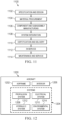
- aircraft manufacturing and service method 1100 may be described in the context of aircraft manufacturing and service method 1100 as shown in Figure 11 and aircraft 1200 as shown in Figure 12 .
- Figure 11 an illustration of an aircraft manufacturing and service method in a form of a block diagram is depicted in accordance with an illustrative example.
- aircraft manufacturing and service method 1100 may include specification and design 1102 of aircraft 1200 in Figure 12 and material procurement 1104.
- aircraft 1200 During production, component and subassembly manufacturing 1106 and system integration 1108 of aircraft 1200 takes place. Thereafter, aircraft 1200 may go through certification and delivery 1110 in order to be placed in service 1112. While in service 1112 by a customer, aircraft 1200 is scheduled for routine maintenance and service 1114, which may include modification, reconfiguration, refurbishment, or other maintenance and service.
- Each of the processes of aircraft manufacturing and service method 1100 may be performed or carried out by a system integrator, a third party, and/or an operator.
- the operator may be a customer.
- a system integrator may include, without limitation, any number of aircraft manufacturers and major-system subcontractors
- a third party may include, without limitation, any number of vendors, subcontractors, and suppliers
- an operator may be an airline, a leasing company, a military entity, a service organization, and so on.
- aircraft 1200 is produced by aircraft manufacturing and service method 1100 of Figure 11 and may include airframe 1202 with plurality of systems 1204 and interior 1206.
- systems 1204 include one or more of propulsion system 1208, electrical system 1210, hydraulic system 1212, and environmental system 1214. Any number of other systems may be included.
- Apparatuses and methods embodied herein may be employed during at least one of the stages of aircraft manufacturing and service method 1100.
- One or more illustrative examples may be manufactured or used during at least one of component and subassembly manufacturing 1106, system integration 1108, in service 1112, or maintenance and service 1114 of Figure 11 .
- a period of resin latency is a period in which the resin remains liquid and does not begin curing. In some illustrative examples, a period of resin latency is in the range of 20-60 min. In some illustrative examples, the resin maintains a viscosity of 100 cps or less. In some illustrative examples, the infusion temperature of the resin infusion and cure tool is in the range of 130-160°C. In some illustrative examples, a closing speed of lowering an upper mold die towards a lower mold die is in the range of about 0.254-5.08 mm/min (0.01-0.2 in/min). In some illustrative examples, a pressure within the sealed cavity of the resin infusion cure tool at the end of closing is in the range of about 68.9-689.5 kPa (10-100 psig).
- the resin infusion and cure tool increases temperature from the infusion temperature to a curing temperature.
- the difference between the infusion temperature and the curing temperature is 40°C or less.
- a ramp rate from the infusion temperature to the curing temperature is in the range from 1-3°C/min.
- curing temperature is in the range of 165-190°C.
- pressure in the sealed cavity of the resin infusion and cure tool remains at about 68.9-689.5 kPa (10-100 psig).
- a cure time is in the range of 45-180 mins.
- the pressure remains at about 68.9-689.5 kPa (10-100 psig) during the temperature ramp down from the curing temperature to the part removal temperature.
- the cured composite part is removed from a hot resin infusion and cure tool in the temperature range of 130-160°C. The cured composite part does not receive additional post cure after removal from the resin infusion and cure tool. The cured composite part comprises a desired level of bonding between the resin and the thermoplastic veil in the preform.
- the resin Due to the heat ramp, the resin maintains mobility longer and can gel (vitrify) after the thermoplastic veil reaches its melting temperature.
- the thermoplastic veil melts over 170 degrees Celsius. As the thermoplastic veil melts it expands. After the thermoplastic veil melts, the resin forms a network around the expanded veil and bonds with the surface of the thermoplastic veil.
- thermoplastic veil As the thermoplastic veil cools back below the melt temp, it tries to contract back to its original size. As the thermoplastic veil is now bonded to the resin it has nowhere to contract from, resulting in a cavitation bubble in the center of the thermoplastic veil.
- the resin is still liquid and the thermoplastic veil is at an original diameter, such as approximately 35um.
- the thermoplastic veil expands as it softens or melts with the resin still in a liquid state.
- the thermoplastic veil can expand to approximately 45-50um as it softens or melts.
- thermoplastic veil After the resin hardens the thermoplastic veil is locked into the expanded size. As the thermoplastic veil cools below the melting temperature again it tries to shrink back to size. With the outer surfaces of the thermoplastic veil locked in place, a cavitation bubble is formed in the center of the thermoplastic veil.
Landscapes
- Engineering & Computer Science (AREA)
- Mechanical Engineering (AREA)
- Chemical & Material Sciences (AREA)
- Composite Materials (AREA)
- Manufacturing & Machinery (AREA)
- Casting Or Compression Moulding Of Plastics Or The Like (AREA)
- Moulding By Coating Moulds (AREA)
Abstract
Description
- The present disclosure generally relates to methods for forming composite structures, and more particularly, to high rate resin infusion technology.
- Composite materials and structures, including resin-infused carbon-fiber laminates, are commonly used in applications requiring high strength and light weight. For example, in the aerospace industry, composite structures are used in increasing quantities to form the fuselage, wings, and other components of aircraft. However, conventional methods and systems for forming composite structures are often time- and labor-intensive, especially for composite structures combining complementary pieces, such as fuselage skins and stringers into a single composite structure. Further, using current aerospace composite-fabrication materials and methods to produce composite structures at high rates would require multiple sets of tooling and processing equipment along with the factory-floor space required to accommodate said equipment. Thus, fabricating high-quality composite structures with aerospace-grade materials to meet performance characteristics at high rates using current production methods would be difficult and expensive, limiting the rate of production at an affordable cost.
- Therefore, it would be desirable to have a method and apparatus that takes into account at least some of the issues discussed above, as well as other possible issues. For example, it would be desirable to present systems and methods for forming composite structures that offer improvements in a rate of production, particularly for composite structures of larger size and complexity, as typically associated with the aerospace industry.
- An example of the present disclosure provides a method of compression resin transfer infusion. A dry preform with a thermoplastic veil is placed onto a lower mold die. An upper mold die is placed over the lower mold die to create an infusion and cure tool having a sealed cavity holding the dry preform, the sealed cavity defining a gap, the gap corresponding to a cavity volume equivalent to an amount of resin to infuse the dry preform. Resin is injected into the gap of the sealed cavity while the infusion and cure tool is maintained at an infusion temperature. The upper mold die is lowered to infuse the dry preform to form a resin-infused preform. The resin-infused preform is cured within the infusion and cure tool to form a cured composite part, wherein curing occurs at a curing temperature higher than the infusion temperature.
- The curing temperature may be sufficient to cause the thermoplastic veil to expand and melt.
- The method may further include lowering a temperature of the infusion and cure tool after the curing from the curing temperature at a ramp down rate, wherein the curing temperature and the ramp down rate are selected to generate cavitation bubbles in the thermoplastic veil in the cured composite part.
- The upper mold die may be lowered at a closing speed of about 0.254-5.08 mm/min (0.01-0.2 in/min).
- Curing may take between 45-180 minutes.
- The infusion temperature may be in a range of 130-160 degrees Celsius.
- The curing temperature may be in a range of 165-190 degrees Celsius.
- A temperature ramp to cure between the infusion temperature and the curing temperature may have a ramp rate of 1-3 degrees Celsius/min.
- A difference between the infusion temperature and the curing temperature may be 40 degrees Celsius or less.
- The method may include removing the cured composite part from the infusion and cure tool while the infusion and cure tool is at a temperature in a range of 130-160 degrees Celsius.
- Another example of the present disclosure provides a method of compression resin transfer infusion. Resin is injected into a gap of a sealed cavity of an infusion and cure tool while the infusion and cure tool is maintained at an infusion temperature, preferably in the range of 130-160 degrees Celsius. An upper mold die of the infusion and cure tool is lowered to infuse a dry preform in the sealed cavity with the resin, preferably in a resin latency condition, to form a resin-infused preform. The temperature of the infusion and cure tool is increased from the infusion temperature to a curing temperature at a desired ramp rate, such as a ramp rate of 1-3 degrees Celsius. The resin-infused preform is cured in the infusion and cure tool to form a cured composite part, wherein curing occurs at the curing temperature higher than the infusion temperature, such as in a range of 165-190 degrees Celsius, wherein the curing temperature is sufficient to cause a thermoplastic veil in the dry preform to expand and melt, preferably thereby joining the resin to the thermoplastic veil.
- The infusion temperature may be in a range of 130-160 degrees Celsius, wherein the ramp rate may be 1-3 degrees Celsius, and the curing temperature may be in a range of 165-190 degrees Celsius.
- The upper mold die may be lowered at a closing speed of about 0.254-5.08 mm/min (0.01-0.2 in/min).
- A pressure within the sealed cavity may be about 68.9-689.5 kPa (10-100 psig) after lowering the upper mold die, and wherein the pressure is maintained at about 68.9-689.5 kPa (10-100 psig) during curing.
- Curing may take between 45-180 minutes.
- A difference between the infusion temperature and the curing temperature may be 40 degrees Celsius or less.
- The method may further include removing the cured composite part from the infusion and cure tool while the infusion and cure tool is at a temperature in a range of 130-160 degrees Celsius.
- The method may further include lowering a temperature of the infusion and cure tool after the curing from the curing temperature at a ramp down rate, wherein the curing temperature and the ramp down rate are selected to generate cavitation bubbles in the thermoplastic veil in the cured composite part.
- Injecting the resin and lowering the upper mold die may occur in 30 min or less.
- Yet another example of the present disclosure provides a method of compression resin transfer infusion to form cavitation bubbles in the cured composite part. Resin is injected into a gap of a sealed cavity of an infusion and cure tool while the infusion and cure tool is maintained at an infusion temperature, preferably in the range of 130-160 degrees Celsius. An upper mold die of the infusion and cure tool is lowered, preferably at a closing speed of about 0.254-5.08 mm/min (0.01-0.2 in/min), to infuse a dry preform in the sealed cavity through its thickness with the resin to form a resin-infused preform, the dry preform comprising a thermoplastic veil. The temperature of the infusion and cure tool is increased from the infusion temperature, particularly to expand the thermoplastic veil while it melts, and preferably to a curing temperature. The resin-infused preform is cured in the infusion and cure tool to form a cured composite part, preferably wherein curing occurs at the curing temperature, and further preferably in a range of 165-190 degrees Celsius, and/or at a curing pressure in a range of about 68.9-689.5 kPa (10-100 psig). A temperature of the infusion and cure tool is lowered after curing, particularly to contract the thermoplastic veil in the cured composite part as the thermoplastic veil cools below a melting temperature of the thermoplastic veil, to generate cavitation bubbles in the thermoplastic veil, particularly as the thermoplastic veil cools below a melting temperature of the thermoplastic veil.
- The infusion temperature may be in a range of 130-160 degrees Celsius, wherein curing may be performed at a curing temperature in a range of 165-190 degrees Celsius.
- Lowering the upper mold die of the infusion and cure tool may be performed at a closing speed of about 0.254-5.08 mm/min (0.01-0.2 in/min). The curing temperature may be sufficient to cause the thermoplastic veil in the resin-infused preform to expand and melt
- The features and functions can be achieved independently in various examples of the present disclosure or may be combined in yet other examples in which further details can be seen with reference to the following description and drawings.
- The novel features believed characteristic of the illustrative examples are set forth in the appended claims. The illustrative examples, however, as well as a preferred mode of use, further objectives and features thereof, will best be understood by reference to the following detailed description of an illustrative example of the present disclosure when read in conjunction with the accompanying drawings, wherein:
-
Figure 1 is an illustration of an aircraft in accordance with an illustrative example; -
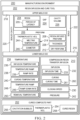
Figure 2 is an illustration of a block diagram of a manufacturing environment in accordance with an illustrative example; -
Figure 3 is an illustration of a temperature chart for an infusion temperature and curing temperature for a high rate resin infusion method in accordance with an illustrative example; -
Figure 4 is an illustration of a resin infusion and cure tool in accordance with an illustrative example; -
Figure 5 is an illustration of interactions between a thermoplastic veil and resin prior to curing in accordance with an illustrative example; -
Figure 6 is an illustration of interactions between a thermoplastic veil and resin during curing in accordance with an illustrative example; -
Figure 7 is an illustration of interactions between a thermoplastic veil and resin after curing in accordance with an illustrative example; -
Figure 8 is a flowchart of a method of compression resin transfer infusion in accordance with an illustrative example; -
Figure 9 is a flowchart of a method of compression resin transfer infusion in accordance with an illustrative example; -
Figure 10 is a flowchart of a method of compression resin transfer infusion to form cavitation bubbles in the cured composite part in accordance with an illustrative example; -
Figure 11 is an illustration of an aircraft manufacturing and service method in a form of a block diagram in accordance with an illustrative example; and -
Figure 12 is an illustration of an aircraft in a form of a block diagram in which an illustrative example may be implemented. - Turning now to
Figure 1 , an illustration of an aircraft is depicted in accordance with an illustrative example.Aircraft 100 haswing 102 andwing 104 attached tobody 106.Aircraft 100 includesengine 108 attached towing 102 andengine 110 attached towing 104. -
Body 106 hastail section 112.Horizontal stabilizer 114,horizontal stabilizer 116, andvertical stabilizer 118 are attached totail section 112 ofbody 106. -
Aircraft 100 is an example of an aircraft that can have composite structures formed using compression resin transfer infusion methods. In some illustrative examples, portions ofbody 106,wing 102, orwing 104 can include a composite structure formed using compression resin transfer infusion methods. - Turning now to
Figure 2 , an illustration of a block diagram of a manufacturing environment is depicted in accordance with an illustrative example. Resin infusion andcure tool 202 in manufacturing environment is used to infuseresin 204 intopreform 206 and cure resin-infusedpreform 208. Compressionresin transfer infusion 210 performed using resin infusion andcure tool 202 utilizes multiple temperatures. - Resin infusion and
cure tool 202 comprises upper mold die 218 and lower mold die 216 sealed together byseals 222.Sealed cavity 220 is present between upper mold die 218 and lower mold die 216. - Compression
resin transfer infusion 210 comprises placingdry preform 212 withthermoplastic veil 214 onto lower mold die 216 of resin infusion andcure tool 202. The raw material ofdry preform 212 can be formed of any desirable type of fiber. In some illustrative examples,dry preform 212 can have a carbon-fiber content up to 70 weight percent. In some illustrative examples, the raw material ofdry preform 212 can include carbon fiber with a knit thread, carbon fiber with a knit thread and a thermoplastic veil, or carbon fiber with a veil. In some illustrative examples,dry preform 212 material can include carbon-fiber-based fabrics, such as non-crimp fabrics (NCFs). In some illustrative examples,dry preform 212 material is a dry multiaxial non-crimped fabric (MA-NCF). In some illustrative examples,dry preform 212 material is a dry unidirectional non-crimped fabric (UD-NCF). - Upper mold die 218 is placed over lower mold die 216 to create infusion and
cure tool 202 having sealedcavity 220 holdingdry preform 212.Sealed cavity 220 definesgap 224.Gap 224 corresponds tocavity volume 226 equivalent to an amount ofresin 204 to infusedry preform 212.Resin 204 is injected intogap 224 of sealedcavity 220 while infusion andcure tool 202 is maintained atinfusion temperature 236. - In some illustrative examples,
resin 204 is an epoxy resin. The resin can have a period oflatency 205. In some illustrative examples,resin 204 comprises a premixed and degassed epoxy resin having period oflatency 205. In some illustrative examples,resin 204 can include epoxies, cyanate esters, benzoxazines, bismaleimides, polyimides, cross-linkable thermoplastics, and in situ polymerizable thermoplastics, or combination thereof. In some illustrative examples,resin 204 can include, without limitation, epoxy/cyanate esters and epoxy/benzoxazines. - As used herein, period of
latency 205 ofresin 204 refers to the time before unacceptable increases in resin viscosity are reached after mixing the components ofresin 204. For example, an epoxy resin can be formed by mixing an epoxy component with a hardener, such as an amine. Once mixed, the epoxy resin will crosslink, increasing its viscosity. The resin can have a period of latency from about 20 minutes to about 1 hour. For example, the resin can have a period of latency of about 30 minutes or less. - Upper mold die 218 is lowered to infuse
dry preform 212 to form resin-infusedpreform 208. Lowering upper mold die 218 infusesresin 204 intodry preform 212 throughthickness 228 ofdry preform 212. - Aspects of
infusion 232, including closingspeed 230,infusion temperature 236, andinfusion time 233, are configured to produce curedcomposite part 252 with desirable values for stiffness and strength. In some illustrative examples, aspects ofinfusion 232, including closingspeed 230,infusion temperature 236, andinfusion time 233, are configured to reduce processing time for curedcomposite part 252. In some illustrative examples, upper mold die 218 is lowered atclosing speed 230 of about 0.254-5.08 mm/min (0.01-0.2 in/min). In some illustrative examples,infusion temperature 236 is in the range of 130-160 degrees Celsius. - Resin-infused
preform 208 is cured within infusion andcure tool 202 to form curedcomposite part 252. Curing 260 occurs at curingtemperature 240 higher thaninfusion temperature 236.Curing temperature 240 is sufficient to causethermoplastic veil 214 to expand and at least one of soften or melt. To bond sufficiently toresin 204,thermoplastic veil 214 at least softens. In some illustrative examples, curingtemperature 240 is atleast melting temperature 244 ofthermoplastic veil 214. -
Temperature 234 of infusion andcure tool 202 is lowered after curing 260 from curingtemperature 240 at ramp downrate 249.Curing temperature 240 and ramp downrate 249 are selected to produce desired bonding betweenthermoplastic veil 254 andresin 204 in curedcomposite part 252.Curing temperature 240 and ramp downrate 249 are selected to generatecavitation bubbles 256 inthermoplastic veil 254 in curedcomposite part 252. In some illustrative examples, cavitation bubbles 256 are an indication of a desired level of bonding betweenthermoplastic veil 254 andresin 204 in curedcomposite part 252. - Time, temperature,
pressure 242, and other aspects of curing 260 are controlled to produce curedcomposite part 252 with desired stiffness and strength. In some illustrative examples, curing 260 takes between 45-180 minutes. In some illustrative examples, curingtemperature 240 is in the range of 165-190 degrees Celsius. In some illustrative examples,temperature ramp 238 to cure betweeninfusion temperature 236 and curingtemperature 240 hasramp rate 239 of 1-3 degrees Celsius/min. In some illustrative examples, a difference betweeninfusion temperature 236 and curingtemperature 240 is 40 degrees Celsius or less. In some illustrative examples,pressure 242 within sealedcavity 220 is about 68.9-689.5 kPa (10-100 psig) after lowering upper mold die 218, andpressure 242 is maintained at about 68.9-689.5 kPa (10-100 psig) during curing 260. -
Curing temperature 240 is selected based onresin 204 andthermoplastic veil 214. In some illustrative examples, curingtemperature 240 can be a temperature from about 170°C to about 190°C. Curing temperature 240 is selected to generate desirable bonding betweenresin 204 andthermoplastic veil 214. - Aspects of
infusion 232 and curing 260 can be set to maximize a production rate of resin infusion andcure tool 202. Aspects ofinfusion 232 and curing 260 can be set to maximize a production rate of curedcomposite part 252. - Curing
time 261 is set to fully curepreform 206 in resin infusion andcure tool 202. Curingtime 261 can be from about 45 minutes to about 180 minutes. - In some illustrative examples, cured
composite part 252 is removed from infusion andcure tool 202 while infusion andcure tool 202 is still warm. In some illustrative examples, curedcomposite part 252 is removed from infusion andcure tool 202 while infusion andcure tool 202 is attemperature 234,removal temperature 250, in a range of 130-160 degrees Celsius. - Cured
composite part 252 has a sufficient degree of stiffness and strength such that curedcomposite part 252 can be safely removed from resin infusion andcure tool 202. Curedcomposite part 252 is sufficiently cured to maintain its shape without any distortion or damage after removal from resin infusion andcure tool 202. Additionally, after removal from resin infusion andcure tool 202, post-curing is not performed on curedcomposite part 252. Curedcomposite part 252 has sufficient stiffness and strength to meet desired targets without additional post-curing. - Each of
infusion temperature 236 and curingtemperature 240 is a temperature value having a variance of less than ±5°C of the desired value. For example, a temperature of 100°C would refer to a temperature maintained between 95°C and 105°C. -
Temperature 234 of resin infusion andcure tool 202 can be maintained/managed by electrical or resistive heating, inductive heating, liquid heating, steam heating, or the like. In some implementations, a mass and heat capacity of lower mold die 216 are configured to prevent large temperature fluctuations due to an external environment or any exothermic or endothermic reactions. For example, lower mold die 216 can comprise materials, such as steel, aluminum, Invar, and the like, selected for their high heat capacity. Similarly, a large mass can help maintain a constant temperature by acting as a heat sink to control exothermic reactions as well maintaining temperature during ambient losses. - Cured
composite part 252 comprises a desired level of bonding between curedresin 258 andthermoplastic veil 254. Due totemperature ramp 238,resin 204 maintains mobility longer and can gel (vitrify) afterthermoplastic veil 214 reaches meltingtemperature 244. In some illustrative examples,thermoplastic veil 214 hasmelting temperature 244 over 170 degrees Celsius. Asthermoplastic veil 214 melts it expands. Afterthermoplastic veil 214 melts,resin 204 forms a network aroundthermoplastic veil 214 whilethermoplastic veil 214 is expanded, andresin 204 bonds with the surface ofthermoplastic veil 214. - As
thermoplastic veil 214 cools back below themelting temperature 244,thermoplastic veil 214 tries to contract back to its original size. Asthermoplastic veil 214 is now bonded toresin 204,thermoplastic veil 214 has nowhere to contract from, resulting in cavitation bubbles 256 in the center ofthermoplastic veil 254. - In some illustrative examples, at temperatures less than melting
temperature 244, such asinfusion temperature 236,resin 204 is still liquid and thethermoplastic veil 214 hasdiameter 246 of an original value. In some illustrative examples,diameter 246 can have an original value of approximately 35um. Attemperature 234 at or abovemelting temperature 244 ofthermoplastic veil 214,thermoplastic veil 214 expands as it softens or melts withresin 204 still in a liquid state. In some illustrative examples,thermoplastic veil 214 can expand to havediameter 246 of approximately 45-50um as it softens or melts. - After
resin 204 hardensthermoplastic veil 214 is locked intodiameter 246 having the expanded size. Asthermoplastic veil 214 cools belowmelting temperature 244 againthermoplastic veil 214 tries to shrink back todiameter 246 having the original size. With the outer surfaces ofthermoplastic veil 214 locked in place, cavitation bubbles 256 are formed in the center ofthermoplastic veil 254. - The illustration of
manufacturing environment 200 inFigure 2 is not meant to imply physical or architectural limitations to the manner in which an illustrative example may be implemented. Other components in addition to or in place of the ones illustrated may be used. Some components may be unnecessary. Also, the blocks are presented to illustrate some functional components. One or more of these blocks may be combined, divided, or combined and divided into different blocks when implemented in an illustrative example. - For example, in some illustrative examples, resin infusion and
cure tool 202 can further include a vacuum system (not depicted). The vacuum system can be configured to evacuategap 224. The vacuum system can create a vacuum ingap 224 prior to injectingresin 204 intogap 224. - In some illustrative examples, curing
temperature 240 is less than meltingtemperature 244. In some illustrative examples, curingtemperature 240 is sufficient to soften but not meltthermoplastic veil 214 such thatthermoplastic veil 214 desirably bonds toresin 204. - Turning now to
Figure 3 , an illustration of a temperature chart for an infusion temperature and curing temperature for a high-rate resin infusion method is depicted in accordance with an illustrative example.Temperature cycle 302 can be used in resin infusion andcure tool 202 ofFigure 2 to form curedcomposite part 252 ofFigure 2 . -
Temperature chart 300 depictstemperature cycle 302 for infusion and curing of a composite material with a thermoplastic veil.Temperature chart 300 hastime 304 as an X-axis andtemperature 306 as a Y-axis. Intemperature cycle 302,infusion 308 is performed atinfusion temperature 310. In some illustrative examples,infusion temperature 310 is in the range of 130-160 degrees Celsius. Afterinfusion 308,temperature ramp 312 occurs astemperature 306 increases to curingtemperature 314. In some illustrative examples,temperature ramp 312 to cure betweeninfusion temperature 310 and curingtemperature 314 has a ramp rate of 1-3 degrees Celsius/min. In some illustrative examples, curingtemperature 314 is in the range of 165-190 degrees Celsius. In some illustrative examples, a difference betweeninfusion temperature 310 and curingtemperature 314 is 40 degrees Celsius or less. - As depicted, curing 316 is carried out at curing
temperature 314. In some illustrative examples, curing 316 takes between 45-180 minutes. Following curing 316,temperature ramp 318 reduces the temperature of the composite material. - The cured composite part is removed at
removal temperature 320. In some illustrative examples,removal temperature 320 is approximately the same asinfusion temperature 310. In some illustrative examples,removal temperature 320 is in the range of 130-160 degrees Celsius. - Turning now to
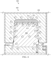
Figure 4 , an illustration of a resin infusion and cure tool is depicted in accordance with an illustrative example. Resin infusion andcure tool 400 is a physical implementation of resin infusion andcure tool 202 ofFigure 2 .Temperature cycle 302 can be performed in resin infusion andcure tool 400 to infuse and cure a composite preform. - Resin infusion and
cure tool 400 comprises upper mold die 404 and lower mold die 406 sealed together byseals 408.Sealed cavity 410 is present between upper mold die 404 and lower mold die 406.Preform 412 is present on lower mold die 406 in sealedcavity 410.Gap 416 is present betweenpreform 412 and upper mold die 404 in sealedcavity 410.Gap 416 corresponds to a cavity volume equivalent to an amount ofresin 414 to infusepreform 412.Resin 414 is injected intogap 416 of sealedcavity 410 while infusion andcure tool 400 is maintained at an infusion temperature. - View 402 is a cross-sectional view through resin infusion and
cure tool 400 afterresin 414 has been injected into sealedcavity 410 formed between upper mold die 404 and lower mold die 406. By lowering upper mold die 404 towards lower mold die 406,resin 414 is infused intopreform 412. - During infusion of
resin 414 intopreform 412, resin infusion andcure tool 400 is kept at an infusion temperature. Afterresin 414 is infused intopreform 412, the infused preform is cured. To cureresin 414 inpreform 412, resin infusion andcure tool 400 is heated from the infusion temperature up to a curing temperature. In some illustrative examples, the difference between the infusion temperature and the curing temperature is up to 40 degrees Celsius. - Turning now to
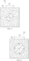
Figure 5 , an illustration of interactions between a thermoplastic veil and resin prior to curing is depicted in accordance with an illustrative example.Thermoplastic veil 501 andresin 502 can be portions of a composite structure ofaircraft 100 ofFigure 1 .Thermoplastic veil 501 andresin 502 are illustrations ofthermoplastic veil 214 andresin 204 ofFigure 2 .Thermoplastic veil 501 andresin 502 can undergotemperature cycle 302 ofFigure 3 .Thermoplastic veil 501 andresin 502 can be processed in resin infusion andcure tool 400 ofFigure 4 . - In
view 500,thermoplastic veil 501 andresin 502 are at a temperature below a melting temperature ofthermoplastic veil 501. Inview 500,thermoplastic veil 501 is at an initial size, havingfirst diameter 504. In some illustrative examples, thermoplastic veil is in the range of approximately 30um to approximately 40um in diameter. In some illustrative examples, thermoplastic veil is approximately 35um in diameter. - Turning now to
Figure 6 , an illustration of interactions between a thermoplastic veil and resin during curing is depicted in accordance with an illustrative example. Inview 600,thermoplastic veil 501 andresin 502 are at a curing temperature, such as curingtemperature 314 ofFigure 3 . Inview 600,thermoplastic veil 501 has expanded due to the curing temperature. Inview 600,thermoplastic veil 501 has diameter of 602. In some illustrative examples,thermoplastic veil 501 can expand between 15%-45%. In some illustrative examples,thermoplastic veil 501 expands to havediameter 602 between approximately 45um to approximately 50um. In some illustrative examples,thermoplastic veil 501 expands to havediameter 602 between approximately 45um to approximately 55um. - Turning now to
Figure 7 , an illustration of interactions between a thermoplastic veil and resin after curing is depicted in accordance with an illustrative example. Inview 700,thermoplastic veil 501 andresin 502 have been cooled below a melting temperature ofthermoplastic veil 501. Asthermoplastic veil 501 cools back below the melting temperature,thermoplastic veil 501 tries to contract back to its original size. Inview 700,resin 502 has hardened intonetwork 702, andthermoplastic veil 501 is now bonded toresin 502. - After
resin 502 hardens,thermoplastic veil 501 is locked into the expanded size. Asthermoplastic veil 501 cools below melting temperature,thermoplastic veil 501 tries to shrink back to size. Due to the bonding ofthermoplastic veil 501 toresin 502,thermoplastic veil 501 has nowhere to contract from resulting in a cavitation bubble in the center of the thermoplastic veil. With the outer surfaces ofthermoplastic veil 501 locked in place,cavitation bubble 704 is formed in the center ofthermoplastic veil 501. - Turning now to
Figure 8 , a flowchart of a method of compression resin transfer infusion is depicted in accordance with an illustrative example.Method 800 can be performed to form a composite part ofaircraft 100 ofFigure 1 .Method 800 can be performed using resin infusion andcure tool 202 to form curedcomposite part 252 ofFigure 2 .Method 800 can be performed usingtemperature cycle 302.Method 800 can be performed using resin infusion andcure tool 400 ofFigure 4 .Method 800 can infuse and curethermoplastic veil 501 andresin 502 ofFigure 5 . -
Method 800 places a dry preform with a thermoplastic veil onto a lower mold die (operation 802).Method 800 places an upper mold die over the lower mold die to create an infusion and cure tool having a sealed cavity holding the dry preform, the sealed cavity defining a gap, the gap corresponding to a cavity volume equivalent to an amount of resin to infuse the dry preform (operation 804).Method 800 injects resin into the gap of the sealed cavity while the infusion and cure tool is maintained at an infusion temperature (operation 806).Method 800 lowers the upper mold die to infuse the dry preform to form a resin-infused preform (operation 808).Method 800 cures the resin-infused preform within the infusion and cure tool to form a cured composite part, wherein curing occurs at a curing temperature higher than the infusion temperature (operation 810). Afterwards,method 800 terminates. - In some illustrative examples, the upper mold die is lowered at a closing speed of about 0.254-5.08 mm/min (0.01-0.2 in/min) (operation 812). In some illustrative examples, the infusion temperature is in the range of 130-160 degrees Celsius (operation 814). In some illustrative examples, the infusion temperature is selected based on a period of latency of the resin.
- In some illustrative examples, the curing temperature is sufficient to cause the thermoplastic veil to expand and melt (operation 816). In some illustrative examples, the curing temperature is sufficient to cause the thermoplastic veil to expand and soften. In some illustrative examples, the curing temperature is sufficient to cause the thermoplastic veil to expand between 15%-45%. In some illustrative examples, the curing temperature is over 170 degrees Celsius.
- In some illustrative examples,
method 800 lowers a temperature of the infusion and cure tool after the curing from the curing temperature at a ramp down rate, wherein the curing temperature and the ramp down rate are selected to generate cavitation bubbles in the thermoplastic veil in the cured composite part (operation 818). During curing the resin forms a network. During curing, the thermoplastic veil bonds to the resin. The cavitation bubbles can result from the thermoplastic veil attempting to shrink to an initial size after the thermoplastic veil bonds to the resin network. In some illustrative examples, curing takes between 45-180 minutes (operation 820). - In some illustrative examples, the curing temperature is in the range of 165-190 degrees Celsius (operation 822). In some illustrative examples, the temperature ramp to cure between the infusion temperature and the curing temperature has a ramp rate of 1-3 degrees Celsius/min (operation 824). In some illustrative examples, a difference between the infusion temperature and the curing temperature is 40 degrees Celsius or less (operation 826).
- In some illustrative examples,
method 800 removes the cured composite part from the infusion and cure tool while the infusion and cure tool is at a temperature in a range of 130-160 degrees Celsius (operation 828). In some illustrative examples, the cured composite part is removed from the infusion and cure tool at the infusion temperature. In some illustrative examples, the cured composite part is removed from the infusion and cure tool after a ramp down with approximately the same ramp rate as the temperature ramp to cure. - In some illustrative examples, the cured composite part is removed from the infusion and cure tool at approximately the infusion temperature. In some illustrative examples, removing the cured composite part while warm will reduce processing time for the cured composite part. Removing the cured composite part while warm will increase the throughput of the infusion and cure tool. Removing the cured composite part while warm can reduce the downtime between infusion of composite parts. Removing the cured composite part while warm can reduce the energy used to prepare the infusion and cure tool for infusion of the next dry preform.
- Turning now to
Figure 9 , a flowchart of a method of compression resin transfer infusion is depicted in accordance with an illustrative example.Method 900 can be performed to form a composite part ofaircraft 100 ofFigure 1 .Method 900 can be performed using resin infusion andcure tool 202 to form curedcomposite part 252 ofFigure 2 .Method 900 can be performed usingtemperature cycle 302.Method 900 can be performed using resin infusion andcure tool 400 ofFigure 4 .Method 900 can infuse and curethermoplastic veil 501 andresin 502 ofFigure 5 . -
Method 900 injects resin into a gap of a sealed cavity of an infusion and cure tool while the infusion and cure tool is maintained at an infusion temperature in the range of 130-160 degrees Celsius (operation 902).Method 900 lowers an upper mold die of the infusion and cure tool to infuse a dry preform in the sealed cavity with the resin in a resin latency condition to form a resin-infused preform (operation 904).Method 900 increases the infusion and cure tool's temperature from the infusion temperature to a curing temperature at a desired ramp rate (operation 906).Method 900 cures the resin-infused preform in the infusion and cure tool to form a cured composite part, wherein curing occurs at the curing temperature higher than the infusion temperature, wherein the curing temperature is sufficient to cause a thermoplastic veil in the dry preform to expand and melt, joining the resin to the thermoplastic veil (operation 908). Afterwards,method 900 terminates. - In some illustrative examples, the infusion temperature is in the range of 130-160 degrees Celsius, the ramp rate is 1-3 degrees Celsius, and the curing temperature is in the range of 165-190 degrees Celsius (operation 909). In some illustrative examples, injecting the resin and lowering the upper mold die occurs in 30 min or less (operation 910). The injection time can be selected based on the latency time.
- In some illustrative examples, the upper mold die is lowered at a closing speed of about 0.254-5.08 mm/min (0.01-0.2 in/min) (operation 912). Lowering the upper mold die infuses the resin into the dry preform through the thickness of the dry preform.
- In some illustrative examples, a pressure within the sealed cavity is about 68.9-689.5 kPa (10-100 psig) after lowering the upper mold die, and wherein the pressure is maintained at about 68.9-689.5 kPa (10-100 psig) during curing (operation 914). In some illustrative examples, curing takes between 45-180 minutes (operation 916). In some illustrative examples, a difference between the infusion temperature and the curing temperature is 40 degrees Celsius or less (operation 918).
- In some illustrative examples,
method 900 lowers a temperature of the infusion and cure tool after the curing from the curing temperature at a ramp down rate, wherein the curing temperature and the ramp down rate are selected to generate cavitation bubbles in the thermoplastic veil in the cured composite part (operation 920). The cavitation bubbles are generated by the thermoplastic veil attempting to shrink to an initial diameter after bonding to the cured resin. - In some illustrative examples,
method 900 removes the cured composite part from the infusion and cure tool while the infusion and cure tool is at a temperature in a range of 130-160 degrees Celsius (operation 922). In some illustrative examples, the cured composite part is removed from the infusion and cure tool at approximately the infusion temperature. In some illustrative examples, removing the cured composite part while warm will reduce processing time for the cured composite part. Removing the cured composite part while warm will increase the throughput of the infusion and cure tool. Removing the cured composite part while warm can reduce the downtime between infusion of composite parts. Removing the cured composite part while warm can reduce the energy used to prepare the infusion and cure tool for infusion of the next dry preform. - Turning now to
Figure 10 , a flowchart of a method of compression resin transfer infusion to form cavitation bubbles in the cured composite part is depicted in accordance with an illustrative example.Method 1000 can be performed to form a composite part ofaircraft 100 ofFigure 1 .Method 1000 can be performed using resin infusion andcure tool 202 to form curedcomposite part 252 ofFigure 2 .Method 1000 can be performed usingtemperature cycle 302.Method 1000 can be performed using resin infusion andcure tool 400 ofFigure 4 .Method 1000 can infuse and curethermoplastic veil 501 andresin 502 ofFigure 5 . -
Method 1000 injects resin into a gap of a sealed cavity of an infusion and cure tool while the infusion and cure tool is maintained at an infusion temperature (operation 1002).Method 1000 lowers an upper mold die of the infusion and cure tool to infuse a dry preform in the sealed cavity through its thickness with the resin to form a resin-infused preform, the dry preform comprising a thermoplastic veil (operation 1004).Method 1000 increases the infusion and cure tool's temperature from the infusion temperature to expand the thermoplastic veil while it melts (operation 1006).Method 1000 cures the resin-infused preform in the infusion and cure tool to form a cured composite part (operation 1008).Method 1000 lowers a temperature of the infusion and cure tool after curing to contract the thermoplastic veil in the cured composite part as the thermoplastic veil cools below a melting temperature of the thermoplastic veil to generate cavitation bubbles in the thermoplastic veil (operation 1010). Afterwards,method 1000 terminates. - In some illustrative examples, the curing temperature is sufficient to cause the thermoplastic veil in the resin-infused preform to expand and melt (operation 1012). In some illustrative examples, the curing temperature is greater than a melting temperature of the thermoplastic veil. In some illustrative examples, the curing temperature is selected so that thermoplastic veil expands sufficiently to cause a cavitation bubble after the thermoplastic veil cools.
- In some illustrative examples, the infusion temperature is in a range of 130-160 degrees Celsius, and wherein curing is performed at a curing temperature in a range of 165-190 degrees Celsius (operation 1014). In some illustrative examples, lowering the upper mold die of the infusion and cure tool is performed at a closing speed of about 0.254-5.08 mm/min (0.01-0.2 in/min) (operation 1016).
- As used herein, the phrase "at least one of," when used with a list of items, means different combinations of one or more of the listed items may be used and only one of each item in the list may be needed. For example, "at least one of item A, item B, or item C" may include, without limitation, item A, item A and item B, or item B. This example also may include item A, item B, and item C or item B and item C. Of course, any combinations of these items may be present. In other examples, "at least one of" may be, for example, without limitation, two of item A; one of item B; and ten of item C; four of item B and seven of item C; or other suitable combinations. The item may be a particular object, thing, or a category. In other words, at least one of means any combination items and number of items may be used from the list but not all of the items in the list are required.
- As used herein, "a number of," when used with reference to items means one or more items.
- Additionally, all numerical values are "about" or "approximately" the indicated value, and take into account experimental error and variations that would be expected by a person having ordinary skill in the art. It should be appreciated that all numerical values and ranges disclosed herein are approximate values and ranges. The terms "about" or "substantial" and "substantially" or "approximately," with reference to amounts or measurement values, are meant that the recited characteristic, parameter, or values need not be achieved exactly. Rather, deviations or variations, including, for example, tolerances, measurement error, measurement accuracy limitations, and other factors known to those skilled in the art, may occur in amounts that do not preclude the effect that the characteristic was intended to provide. As used herein, "about" is to mean within+/- 10 % of a stated target value, maximum, or minimum value.
- The flowcharts and block diagrams in the different depicted examples illustrate the architecture, functionality, and operation of some possible implementations of apparatuses and methods in an illustrative example. In this regard, each block in the flowcharts or block diagrams may represent at least one of a module, a segment, a function, or a portion of an operation or step.
- In some alternative implementations of an illustrative example, the function or functions noted in the blocks may occur out of the order noted in the figures. For example, in some cases, two blocks shown in succession may be executed substantially concurrently, or the blocks may sometimes be performed in the reverse order, depending upon the functionality involved. Also, other blocks may be added in addition to the illustrated blocks in a flowchart or block diagram. Some blocks may be optional. For example,
operation 812 throughoperation 828 may be optional. As another example, operation 910 throughoperation 922 may be optional. As a further example,operation 1012 may be optional. - Illustrative examples of the present disclosure may be described in the context of aircraft manufacturing and
service method 1100 as shown inFigure 11 andaircraft 1200 as shown inFigure 12 . Turning first toFigure 11 , an illustration of an aircraft manufacturing and service method in a form of a block diagram is depicted in accordance with an illustrative example. During pre-production, aircraft manufacturing andservice method 1100 may include specification anddesign 1102 ofaircraft 1200 inFigure 12 andmaterial procurement 1104. - During production, component and
subassembly manufacturing 1106 andsystem integration 1108 ofaircraft 1200 takes place. Thereafter,aircraft 1200 may go through certification anddelivery 1110 in order to be placed inservice 1112. While inservice 1112 by a customer,aircraft 1200 is scheduled for routine maintenance andservice 1114, which may include modification, reconfiguration, refurbishment, or other maintenance and service. - Each of the processes of aircraft manufacturing and
service method 1100 may be performed or carried out by a system integrator, a third party, and/or an operator. In these examples, the operator may be a customer. For the purposes of this description, a system integrator may include, without limitation, any number of aircraft manufacturers and major-system subcontractors; a third party may include, without limitation, any number of vendors, subcontractors, and suppliers; and an operator may be an airline, a leasing company, a military entity, a service organization, and so on. - With reference now to
Figure 12 , an illustration of an aircraft in a form of a block diagram is depicted in which an illustrative example may be implemented. In this example,aircraft 1200 is produced by aircraft manufacturing andservice method 1100 ofFigure 11 and may includeairframe 1202 with plurality ofsystems 1204 and interior 1206. Examples ofsystems 1204 include one or more ofpropulsion system 1208,electrical system 1210,hydraulic system 1212, andenvironmental system 1214. Any number of other systems may be included. - Apparatuses and methods embodied herein may be employed during at least one of the stages of aircraft manufacturing and
service method 1100. One or more illustrative examples may be manufactured or used during at least one of component andsubassembly manufacturing 1106,system integration 1108, inservice 1112, or maintenance andservice 1114 ofFigure 11 . - The illustrative examples provide compression resin transfer infusion. A period of resin latency is a period in which the resin remains liquid and does not begin curing. In some illustrative examples, a period of resin latency is in the range of 20-60 min. In some illustrative examples, the resin maintains a viscosity of 100 cps or less. In some illustrative examples, the infusion temperature of the resin infusion and cure tool is in the range of 130-160°C. In some illustrative examples, a closing speed of lowering an upper mold die towards a lower mold die is in the range of about 0.254-5.08 mm/min (0.01-0.2 in/min). In some illustrative examples, a pressure within the sealed cavity of the resin infusion cure tool at the end of closing is in the range of about 68.9-689.5 kPa (10-100 psig).
- The resin infusion and cure tool increases temperature from the infusion temperature to a curing temperature. In some illustrative examples, the difference between the infusion temperature and the curing temperature is 40°C or less. In some illustrative examples, a ramp rate from the infusion temperature to the curing temperature is in the range from 1-3°C/min.
- In some illustrative examples, curing temperature is in the range of 165-190°C. During curing, the pressure in the sealed cavity of the resin infusion and cure tool remains at about 68.9-689.5 kPa (10-100 psig). In some illustrative examples, a cure time is in the range of 45-180 mins.
- In some illustrative examples, the pressure remains at about 68.9-689.5 kPa (10-100 psig) during the temperature ramp down from the curing temperature to the part removal temperature. In some illustrative examples, the cured composite part is removed from a hot resin infusion and cure tool in the temperature range of 130-160°C. The cured composite part does not receive additional post cure after removal from the resin infusion and cure tool. The cured composite part comprises a desired level of bonding between the resin and the thermoplastic veil in the preform.
- Due to the heat ramp, the resin maintains mobility longer and can gel (vitrify) after the thermoplastic veil reaches its melting temperature. In some illustrative examples, the thermoplastic veil melts over 170 degrees Celsius. As the thermoplastic veil melts it expands. After the thermoplastic veil melts, the resin forms a network around the expanded veil and bonds with the surface of the thermoplastic veil.
- As the thermoplastic veil cools back below the melt temp, it tries to contract back to its original size. As the thermoplastic veil is now bonded to the resin it has nowhere to contract from, resulting in a cavitation bubble in the center of the thermoplastic veil.
- In some illustrative examples, at temperatures less than the melting temperature, the resin is still liquid and the thermoplastic veil is at an original diameter, such as approximately 35um. At temperatures at or above a melting temperature of the thermoplastic veil, the thermoplastic veil expands as it softens or melts with the resin still in a liquid state. In some illustrative examples, the thermoplastic veil can expand to approximately 45-50um as it softens or melts.
- After the resin hardens the thermoplastic veil is locked into the expanded size. As the thermoplastic veil cools below the melting temperature again it tries to shrink back to size. With the outer surfaces of the thermoplastic veil locked in place, a cavitation bubble is formed in the center of the thermoplastic veil.
- The description of the different illustrative examples has been presented for purposes of illustration and description, and is not intended to be exhaustive or limited to the examples in the form disclosed. Many modifications and variations will be apparent to those of ordinary skill in the art. Further, different illustrative examples may provide different features as compared to other illustrative examples. The example or examples selected are chosen and described in order to best explain the principles of the examples, the practical application, and to enable others of ordinary skill in the art to understand the disclosure for various examples with various modifications as are suited to the particular use contemplated.
Claims (15)
- A method (800) of compression resin transfer infusion comprising:placing (802) a dry preform (212, 412) with a thermoplastic veil (214, 501) onto a lower mold die (216, 406) ;placing (804) an upper mold die (218, 404) over the lower mold die (216, 406) to create an infusion and cure tool (202, 400) having a sealed cavity (220, 410) holding the dry preform (212, 412), the sealed cavity (220, 410) defining a gap (224, 416), the gap (224, 416) corresponding to a cavity volume (226) equivalent to an amount of resin (204, 414, 502) to infuse the dry preform (212, 412);injecting (806) resin (204, 414, 502) into the gap (224, 416) of the sealed cavity (220, 410) while the infusion and cure tool (202, 400) is maintained at an infusion temperature (236, 310);lowering (808) the upper mold die (218, 404) to infuse the dry preform (212, 412) to form a resin-infused preform (208); andcuring (810, 260, 316) the resin-infused preform (208) within the infusion and cure tool (202, 400) to form a cured composite part (252), wherein curing (260, 316) occurs at a curing temperature (240, 314) higher than the infusion temperature (236, 310).
- The method (800) of claim 1, wherein (816) the curing temperature (240, 314) is sufficient to cause the thermoplastic veil (214, 501) to expand and melt.
- The method (800) of claim 1 or 2, further comprising:
lowering (818) a temperature of the infusion and cure tool (202, 400) after the curing (260, 316) from the curing temperature (240, 314) at a ramp down rate (249), wherein the curing temperature (240, 314) and the ramp down rate (249) are selected to generate cavitation bubbles (256, 704) in the thermoplastic veil (214, 501) in the cured composite part (252). - The method (800) of any of the preceding claims, wherein:(812) the upper mold die (218, 404) is lowered at a closing speed (230) of about 0.254-5.08 mm/min (0.01-0.2 in/min); and/or(820) curing (260, 316) takes between 45-180 minutes; and/or(814) the infusion temperature (236, 310) is in a range of 130-160 degrees Celsius; and/or(822) the curing temperature (240, 314) is in a range of 165-190 degrees Celsius.
- The method (800) of any of the preceding claims, wherein (824) a temperature ramp (238, 312) to cure between the infusion temperature (236, 310) and the curing temperature (240, 314) has a ramp rate (239) of 1-3 degrees Celsius/min.
- The method (800) of any of the preceding claims, wherein (826) a difference between the infusion temperature (236, 310) and the curing temperature (240, 314) is 40 degrees Celsius or less.
- The method (800) of any of the preceding claims, further comprising:
removing (828) the cured composite part (252) from the infusion and cure tool (202, 400) while the infusion and cure tool (202, 400) is at a temperature (234) in a range of 130-160 degrees Celsius. - A method (900) of compression resin transfer infusion comprising:injecting (902) resin (204, 414, 502) into a gap (224, 416) of a sealed cavity (220, 410) of an infusion and cure tool (202, 400) while the infusion and cure tool (202, 400) is maintained at an infusion temperature (236, 310) ;lowering (904) an upper mold die (218, 404) of the infusion and cure tool (202, 400) to infuse a dry preform (212, 412) in the sealed cavity (220, 410) with the resin (204, 414, 502) in a resin latency condition to form a resin-infused preform (208);increasing (906) the infusion and cure tool's (202, 400) temperature (234) from the infusion temperature (236, 310) to a curing temperature (240, 314) at a desired ramp rate; andcuring (908, 260, 316) the resin-infused preform (208) in the infusion and cure tool (202, 400) to form a cured composite part (252), wherein curing (260, 316) occurs at the curing temperature (240, 314) higher than the infusion temperature (236, 310), wherein the curing temperature (240, 314) is sufficient to cause a thermoplastic veil (214, 501) in the dry preform (212, 412) to expand and melt, joining the resin to the thermoplastic veil (214, 501).
- The method (900) of claim 8, wherein:the infusion temperature (236, 310) is in a range of 130-160 degrees Celsius, wherein the ramp rate is 1-3 degrees Celsius, and the curing temperature (240, 314) is in a range of 165-190 degrees Celsius; and/or(912) the upper mold die (218, 404) is lowered at a closing speed (230) of about 0.254-5.08 mm/min (0.01-0.2 in/min); and/or(914) a pressure (242) within the sealed cavity (220, 410) is about 68.9-689.5 kPa (10-100 psig) after lowering the upper mold die (218, 404), and wherein the pressure (242) is maintained at about 68.9-689.5 kPa (10-100 psig) during curing (260, 316).
- The method (900) of claim 8 or 9, wherein:(916) curing (260, 316) takes between 45-180 minutes; and/or(918) a difference between the infusion temperature (236, 310) and the curing temperature (240, 314) is 40 degrees Celsius or less.
- The method (900) of any one of claims 8-10, further comprising:
removing (922) the cured composite part (252) from the infusion and cure tool (202, 400) while the infusion and cure tool (202, 400) is at a temperature (234) in a range of 130-160 degrees Celsius. - The method (900) of any one of claims 8-11, further comprising:
lowering (920) a temperature (234, 302) of the infusion and cure tool (202, 400) after the curing (260, 316) from the curing temperature (240, 314) at a ramp down rate (249), wherein the curing temperature (240, 314) and the ramp down rate (249) are selected to generate cavitation bubbles (256, 704) in the thermoplastic veil (214, 501) in the cured composite part (252) . - The method (900) of any one of claims 8-12, wherein (910) injecting the resin (204, 414, 502) and lowering the upper mold die (218, 404) occurs in 30 min or less.
- A method (1000) of compression resin transfer infusion to form cavitation bubbles (256, 704) in a cured composite part (252) comprising:injecting (1002) resin (204, 414, 502) into a gap (224, 416) of a sealed cavity (220, 410) of an infusion and cure tool (202, 400) while the infusion and cure tool (202, 400) is maintained at an infusion temperature (236, 310) ;lowering (1004) an upper mold die (218, 404) of the infusion and cure tool (202, 400) to infuse a dry preform (212, 412) in the sealed cavity (220, 410) through its thickness (228) with the resin (204, 414, 502) to form a resin-infused preform (208), the dry preform (212, 412) comprising a thermoplastic veil (214, 501);increasing (1006) the infusion and cure tool (202, 400)'s temperature (234) from the infusion temperature (236, 310) to expand the thermoplastic veil while it melts;curing (1008, 260, 316) the resin-infused preform (208) in the infusion and cure tool (202, 400) to form a cured composite part (252); andlowering (1010) the temperature (234) of the infusion and cure tool (202, 400) after curing (260, 316) to contract the thermoplastic veil (214, 501) in the cured composite part (252) as the thermoplastic veil (214, 501) cools below a melting temperature of the thermoplastic veil (214, 501) to generate cavitation bubbles (256, 704) in the thermoplastic veil (214, 501).
- The method of claim 14, wherein:the infusion temperature (236, 310) is in a range of 130-160 degrees Celsius, and wherein curing is performed at a curing temperature (240, 314) in a range of 165-190 degrees Celsius, preferably wherein (1012) the curing temperature (240, 314) is sufficient to cause the thermoplastic veil (214, 501) in the resin-infused preform (208) to expand and melt; and/orlowering (1004) the upper mold die (218, 404) of the infusion and cure tool (202, 400) is performed at a closing speed (230) of about 0.254-5.08 mm/min (0.01-0.2 in/min).
Applications Claiming Priority (1)
| Application Number | Priority Date | Filing Date | Title |
|---|---|---|---|
| US18/501,423 US12466142B2 (en) | 2023-11-03 | 2023-11-03 | Compression resin transfer infusion methods |
Publications (1)
| Publication Number | Publication Date |
|---|---|
| EP4549136A1 true EP4549136A1 (en) | 2025-05-07 |
Family
ID=92909665
Family Applications (1)
| Application Number | Title | Priority Date | Filing Date |
|---|---|---|---|
| EP24202480.0A Pending EP4549136A1 (en) | 2023-11-03 | 2024-09-25 | Compression resin transfer infusion methods |
Country Status (4)
| Country | Link |
|---|---|
| US (1) | US12466142B2 (en) |
| EP (1) | EP4549136A1 (en) |
| JP (1) | JP2025077979A (en) |
| CN (1) | CN119928308A (en) |
Citations (3)
| Publication number | Priority date | Publication date | Assignee | Title |
|---|---|---|---|---|
| EP2855122B1 (en) * | 2012-05-30 | 2020-04-15 | Gurit (UK) Ltd. | Press moulding method |
| WO2022081861A1 (en) * | 2020-10-14 | 2022-04-21 | The Boeing Company | High-rate resin-infusion methods and tooling for aircraft structures |
| WO2022265727A1 (en) * | 2021-06-14 | 2022-12-22 | Cytec Industries, Inc. | A process for manufacturing composite articles, and composite articles made thereby |
Family Cites Families (6)
| Publication number | Priority date | Publication date | Assignee | Title |
|---|---|---|---|---|
| BR0009055A (en) | 1999-03-18 | 2002-01-08 | David H Stewart | Method of manufacturing part molded on a press and machine for molding a part |
| FI107035B (en) * | 1999-09-10 | 2001-05-31 | Natural Colour Kari Kirjavaine | Method and apparatus for making a plastic film and a plastic film |
| GB0417634D0 (en) * | 2004-08-09 | 2004-09-08 | Structural Polymer Systems Ltd | Mould |
| US20120108132A1 (en) * | 2010-10-28 | 2012-05-03 | General Electric Company | Composite Compositions |
| JP5876791B2 (en) * | 2012-08-28 | 2016-03-02 | 本田技研工業株式会社 | Method and apparatus for molding fiber reinforced resin molded product |
| WO2022081884A1 (en) | 2020-10-14 | 2022-04-21 | The Boeing Company | High rate resin infusion horizontal stabilizer stiffened skin technology |
-
2023
- 2023-11-03 US US18/501,423 patent/US12466142B2/en active Active
-
2024
- 2024-07-25 JP JP2024119596A patent/JP2025077979A/en active Pending
- 2024-08-21 CN CN202411150974.8A patent/CN119928308A/en active Pending
- 2024-09-25 EP EP24202480.0A patent/EP4549136A1/en active Pending
Patent Citations (3)
| Publication number | Priority date | Publication date | Assignee | Title |
|---|---|---|---|---|
| EP2855122B1 (en) * | 2012-05-30 | 2020-04-15 | Gurit (UK) Ltd. | Press moulding method |
| WO2022081861A1 (en) * | 2020-10-14 | 2022-04-21 | The Boeing Company | High-rate resin-infusion methods and tooling for aircraft structures |
| WO2022265727A1 (en) * | 2021-06-14 | 2022-12-22 | Cytec Industries, Inc. | A process for manufacturing composite articles, and composite articles made thereby |
Also Published As
| Publication number | Publication date |
|---|---|
| CN119928308A (en) | 2025-05-06 |
| US12466142B2 (en) | 2025-11-11 |
| US20250144895A1 (en) | 2025-05-08 |
| JP2025077979A (en) | 2025-05-19 |
Similar Documents
| Publication | Publication Date | Title |
|---|---|---|
| JP6966848B2 (en) | Composite structure with reinforcing material and its manufacturing method | |
| CA2888974C (en) | Joining composite components using low temperature thermoplastic film fusion | |
| EP2921583B1 (en) | Method of fabricating a composite structure using temporarily stitched preforms, and composite preform | |
| US8790487B2 (en) | Method of fabricating a part out of reinforced composite material, and a method of repairing such a part | |
| EP1522549B1 (en) | Heat-settable resins | |
| US11458719B2 (en) | Method for joining by bonding of parts, in particular composite parts having fibrous reinforcement | |
| Ben et al. | Fast fabrication method and evaluation of performance of hybrid FRTPs for applying them to automotive structural members | |
| US7858012B2 (en) | Automated prototyping of a composite airframe | |
| EP4549136A1 (en) | Compression resin transfer infusion methods | |
| US11826965B2 (en) | Method for making consolidated composite structures | |
| EP4353460B1 (en) | Methods and structural gap filler for one-up assembly | |
| CA2770467C (en) | Process for prolonging the processing window of thermosetting resins | |
| JP2024141918A (en) | Structure and manufacturing method thereof | |
| CN116728818A (en) | Ultrasonic welding method for fiber reinforced thermosetting composite material | |
| Knoeller et al. | Polymer matrix composite manufacturing induced defects | |
| Krishnamaraja et al. | Effect of post-curing temperature variation on mechanical properties of adhesively bonded composite laminates |
Legal Events
| Date | Code | Title | Description |
|---|---|---|---|
| PUAI | Public reference made under article 153(3) epc to a published international application that has entered the european phase |
Free format text: ORIGINAL CODE: 0009012 |
|
| STAA | Information on the status of an ep patent application or granted ep patent |
Free format text: STATUS: THE APPLICATION HAS BEEN PUBLISHED |
|
| AK | Designated contracting states |
Kind code of ref document: A1 Designated state(s): AL AT BE BG CH CY CZ DE DK EE ES FI FR GB GR HR HU IE IS IT LI LT LU LV MC ME MK MT NL NO PL PT RO RS SE SI SK SM TR |
|
| STAA | Information on the status of an ep patent application or granted ep patent |
Free format text: STATUS: REQUEST FOR EXAMINATION WAS MADE |
|
| 17P | Request for examination filed |
Effective date: 20251025 |
|
| REG | Reference to a national code |
Ref country code: DE Ref legal event code: R079 Free format text: PREVIOUS MAIN CLASS: B29C0070480000 Ipc: B29C0070540000 |
|
| RIC1 | Information provided on ipc code assigned before grant |
Ipc: B29C 70/54 20060101AFI20251209BHEP Ipc: B29C 45/56 20060101ALI20251209BHEP Ipc: B29C 70/44 20060101ALI20251209BHEP Ipc: B29C 70/46 20060101ALI20251209BHEP Ipc: B29C 70/48 20060101ALI20251209BHEP |
|
| GRAP | Despatch of communication of intention to grant a patent |
Free format text: ORIGINAL CODE: EPIDOSNIGR1 |
|
| STAA | Information on the status of an ep patent application or granted ep patent |
Free format text: STATUS: GRANT OF PATENT IS INTENDED |
|
| INTG | Intention to grant announced |
Effective date: 20260122 |
|
| P01 | Opt-out of the competence of the unified patent court (upc) registered |
Free format text: CASE NUMBER: UPC_APP_0002641_4549136/2026 Effective date: 20260126 |