EP4549040A1 - Rolling mill - Google Patents
Rolling mill Download PDFInfo
- Publication number
- EP4549040A1 EP4549040A1 EP23854762.4A EP23854762A EP4549040A1 EP 4549040 A1 EP4549040 A1 EP 4549040A1 EP 23854762 A EP23854762 A EP 23854762A EP 4549040 A1 EP4549040 A1 EP 4549040A1
- Authority
- EP
- European Patent Office
- Prior art keywords
- liner
- housing
- rolling mill
- roll chock
- liners
- Prior art date
- Legal status (The legal status is an assumption and is not a legal conclusion. Google has not performed a legal analysis and makes no representation as to the accuracy of the status listed.)
- Pending
Links
Images


Classifications
-
- B—PERFORMING OPERATIONS; TRANSPORTING
- B21—MECHANICAL METAL-WORKING WITHOUT ESSENTIALLY REMOVING MATERIAL; PUNCHING METAL
- B21B—ROLLING OF METAL
- B21B31/00—Rolling stand structures; Mounting, adjusting, or interchanging rolls, roll mountings, or stand frames
- B21B31/02—Rolling stand frames or housings; Roll mountings ; Roll chocks
-
- B—PERFORMING OPERATIONS; TRANSPORTING
- B21—MECHANICAL METAL-WORKING WITHOUT ESSENTIALLY REMOVING MATERIAL; PUNCHING METAL
- B21B—ROLLING OF METAL
- B21B33/00—Safety devices not otherwise provided for; Breaker blocks; Devices for freeing jammed rolls for handling cobbles; Overload safety devices
-
- F—MECHANICAL ENGINEERING; LIGHTING; HEATING; WEAPONS; BLASTING
- F16—ENGINEERING ELEMENTS AND UNITS; GENERAL MEASURES FOR PRODUCING AND MAINTAINING EFFECTIVE FUNCTIONING OF MACHINES OR INSTALLATIONS; THERMAL INSULATION IN GENERAL
- F16F—SPRINGS; SHOCK-ABSORBERS; MEANS FOR DAMPING VIBRATION
- F16F15/00—Suppression of vibrations in systems; Means or arrangements for avoiding or reducing out-of-balance forces, e.g. due to motion
- F16F15/02—Suppression of vibrations of non-rotating, e.g. reciprocating systems; Suppression of vibrations of rotating systems by use of members not moving with the rotating systems
- F16F15/04—Suppression of vibrations of non-rotating, e.g. reciprocating systems; Suppression of vibrations of rotating systems by use of members not moving with the rotating systems using elastic means
-
- B—PERFORMING OPERATIONS; TRANSPORTING
- B21—MECHANICAL METAL-WORKING WITHOUT ESSENTIALLY REMOVING MATERIAL; PUNCHING METAL
- B21B—ROLLING OF METAL
- B21B13/00—Metal-rolling stands, i.e. an assembly composed of a stand frame, rolls, and accessories
- B21B13/02—Metal-rolling stands, i.e. an assembly composed of a stand frame, rolls, and accessories with axes of rolls arranged horizontally
- B21B2013/028—Sixto, six-high stands
-
- B—PERFORMING OPERATIONS; TRANSPORTING
- B21—MECHANICAL METAL-WORKING WITHOUT ESSENTIALLY REMOVING MATERIAL; PUNCHING METAL
- B21B—ROLLING OF METAL
- B21B31/00—Rolling stand structures; Mounting, adjusting, or interchanging rolls, roll mountings, or stand frames
- B21B31/02—Rolling stand frames or housings; Roll mountings ; Roll chocks
- B21B2031/021—Integral tandem mill housings
-
- B—PERFORMING OPERATIONS; TRANSPORTING
- B21—MECHANICAL METAL-WORKING WITHOUT ESSENTIALLY REMOVING MATERIAL; PUNCHING METAL
- B21B—ROLLING OF METAL
- B21B2203/00—Auxiliary arrangements, devices or methods in combination with rolling mills or rolling methods
- B21B2203/44—Vibration dampers
-
- B—PERFORMING OPERATIONS; TRANSPORTING
- B21—MECHANICAL METAL-WORKING WITHOUT ESSENTIALLY REMOVING MATERIAL; PUNCHING METAL
- B21B—ROLLING OF METAL
- B21B37/00—Control devices or methods specially adapted for metal-rolling mills or the work produced thereby
- B21B37/007—Control for preventing or reducing vibration, chatter or chatter marks
-
- F—MECHANICAL ENGINEERING; LIGHTING; HEATING; WEAPONS; BLASTING
- F16—ENGINEERING ELEMENTS AND UNITS; GENERAL MEASURES FOR PRODUCING AND MAINTAINING EFFECTIVE FUNCTIONING OF MACHINES OR INSTALLATIONS; THERMAL INSULATION IN GENERAL
- F16F—SPRINGS; SHOCK-ABSORBERS; MEANS FOR DAMPING VIBRATION
- F16F7/00—Vibration-dampers; Shock-absorbers
Definitions
- the present invention relates to a rolling mill.
- chattering occurs in the rolling mill and a sheet thickness defect or a pattern in a sheet width direction called chatter mark occurs in a material to be rolled, which sometimes adversely affects quality.
- a method providing, in a rolling mill, a sensor that detects vibration and monitoring vibration and performing rolling with speed reduced to a speed range in which vibration does not occur is adopted.
- this method deteriorates production efficiency, many proposals for reducing vibration that causes chattering of a rolling mill have been made.
- Patent Literature 1 discloses a technique of reducing vibration by providing, on opposed sides of the bearing main body, via a damping mechanism that damps vibration in the up-down direction, a wedge-shaped member having an inclined sliding surface further separated from a material to be rolled from an entry side toward a delivery side and a contact end face that comes into contact with a delivery side member.
- Patent Literature 2 discloses a technique of reducing vibration by including a beam having elasticity attached between two roll chocks or between two pressure stands of a backup roll of a rolling mill, an added mass mounted on the beam, and a damper that brakes the added mass.
- the present invention has been made in view of the above problems, and an object of the present invention is to provide a rolling mill capable of, while suppressing a production loss, inexpensively reducing vibration that causes chattering.
- the liner may be configured using a damping material.
- the damping material may be a viscoelastic body
- the liner may be configured by a liner main body section made of a metal material and the viscoelastic body that covers the liner main body section.
- the upper and lower rolls may be at least one of a pair of work rolls vertically disposed with a material to be rolled interposed therebetween, a pair of intermediate rolls respectively in contact with the pair of work rolls, and a pair of backup rolls respectively in contact with the pair of intermediate rolls.
- the rolling mill according to the present invention has an effect of capable of, while suppressing a production loss, inexpensively reducing vibration that causes chattering.
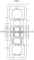
- FIG. 1 is a schematic diagram of a rolling mill 1 according to the embodiment.
- the rolling mill 1 according to the embodiment includes a housing 2 and a pair of work rolls 3a and 3b, a pair of intermediate rolls 5a and 5b, backup rolls 7a and 7b, and the like provided on an upper side and a lower side.
- the pair of intermediate rolls 5a and 5b is respectively in contact with the work rolls 3a and 3b.
- the backup rolls 7a and 7b are respectively in contact with the intermediate rolls 5a and 5b.
- the rolling mill 1 according to the embodiment is a six-stage rolling mill that carries out rolling on a steel sheet S that is a material to be rolled.
- a steel type of the steel sheet S is, for example, a steel sheet for an automobile outer plate.
- the present invention is not limited to the six-stage rolling mill and can also be applied to a four-stage rolling mill having four stages without an intermediate roll or a multi-stage rolling mill having more than six stages.
- a work roll chock 4a rotatably supports one end in the axial direction of the work roll 3a on the upper side.
- the work roll chock 4b rotatably supports one end in the axial direction of the work roll 3b on the lower side.
- the intermediate roll chock 6a rotatably supports one end in the axial direction of the intermediate roll 5a on the upper side.
- the intermediate roll chock 6b rotatably supports one end in the axial direction of the intermediate roll 5b on the lower side.
- the backup roll chock 8a rotatably supports one end in the axial direction of the backup roll 7a on the upper side.
- the backup roll chock 8b rotatably supports one end in the axial direction of the backup roll 7b on the lower side.
- work roll chock liners 9a and 9b are respectively provided on housing counter surfaces of the work roll chocks 4a and 4b.
- housing blocks 10a and 10b are provided at portions facing the work roll chocks 4a and 4b in the width direction.
- housing liners 11a and 11b are respectively provided on surfaces facing the work roll chocks 4a and 4b. Note that the surfaces facing the work roll chocks 4a and 4b are housing surfaces corresponding to the housing counter surfaces of the work roll chocks 4a and 4b.
- the work roll chock liners 9a and 9b and the housing liners 11a and 11b are disposed with facing surfaces thereof in contact with each other.
- Lubricating oil such as grease is filled between the work roll chock liner 9a and the housing liner 11a and between the work roll chock liner 9b and the housing liner 11b.
- work roll chocks work roll chock liners, housing blocks, and housing liners are also respectively disposed at the other ends in the axial direction of the work rolls 3a and 3b.
- intermediate roll chocks are also respectively disposed at the other ends in the axial direction of the intermediate rolls 5a and 5b.
- backup roll chocks are also respectively disposed at the other ends in the axial direction of the backup rolls 7a and 7b.
- the work rolls 3a and 3b are also respectively simply described as work rolls 3 unless being particularly distinguished.
- the work roll chocks 4a and 4b are also respectively simply described as work roll chocks 4 unless being particularly distinguished.
- the intermediate rolls 5a and 5b are also respectively simply described as intermediate rolls 5 unless being particularly distinguished.
- the intermediate roll chocks 6a and 6b are also respectively simply described as intermediate roll chocks 6 unless being particularly distinguished.
- the backup rolls 7a and 7b are also respectively simply described as backup rolls 7 unless being particularly distinguished.
- the backup roll chocks 8a and 8b are also respectively simply described as backup roll chocks 8 unless being particularly distinguished.
- the work roll chock liners 9a and 9b are also respectively simply described as work roll chock liners 9 unless being particularly distinguished.
- the housing blocks 10a and 10b are also respectively simply described as a housing blocks 10 unless being particularly distinguished.
- the housing liners 11a and 11b are also respectively simply described as housing liners 11 unless being particularly distinguished.
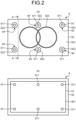
- FIG. 2(a) is a schematic diagram of the work roll chock liner 9 viewed from the front side.
- FIG. 2(b) is a schematic diagram of the work roll chock liner 9 viewed from the rear side.
- FIG. 3 is a diagram illustrating an A-A cross section in FIG. 2(a) of the work roll chock liner 9.
- the front side of the work roll chock liner 9 is a side that comes into contact with the housing liner 11 in the thickness direction of the work roll chock liner 9 when the work roll chock liner 9 is attached to the rolling mill 1.
- the rear side of the work roll chock liner 9 is a side that comes into contact with the work roll chock 4 in the thickness direction of the work roll chock liner 9 when the work roll chock liner 9 is attached to the rolling mill 1.
- the work roll chock liner 9 is configured by a liner main body section 91 made of a metal material such as brass and a viscoelastic body 92 that is a damping material serving as vibration reducing means having a vibration reducing function.
- the material of the liner main body section 91 is not limited to the metal material and only has to have strength enough to withstand fixing by bolts and may be, for example, a resin material or a ceramic material having rigidity higher than the rigidity of the viscoelastic body 92.
- the liner main body section 91 is a plate-like member elongated in the axial direction of the work roll 3, has an edge portion on the rear side cut down by one step over the entire circumference, and is formed in a shape convex to the work roll chock 4 side in the thickness direction.
- the viscoelastic body 92 is a plate-like member larger than the liner main body section 91 and has an internal space along the outer contour shape (the convex shape) of the liner main body section 91 to be capable of enclosing the liner main body section 91. At the same time, a part on the rear side of the viscoelastic body 92 is opened such that a surface other than the edge portion on the rear side of the liner main body section 91 is exposed.
- the viscoelastic body 92 is stuck and fixed to the liner main body section 91 by an adhesive in a state in which the viscoelastic body 92 covers the liner main body section 91 such that the edge portion on the rear side of the viscoelastic body 92 is caught by the edge portion lowered by one step on the rear side of the liner main body section 91.
- the edge portion on the rear side of the viscoelastic body 92 is hooked on the edge portion lowered by one step on the rear side of the liner main body section 91 and the viscoelastic body 92 encloses the liner main body section 91.
- the viscoelastic body 92 may be fastened and fixed to the liner main body section 91 by a fastening member such as a bolt.
- the viscoelastic body 92 may be fixed to the liner main body section 91 by the adhesive and the fastening member.
- the viscoelastic body 92 for example, damping rubber excellent in heat resistance and water resistance only has to be used.
- the viscoelastic body 92 suitably has a characteristic of a loss coefficient of 0.2 or more in a frequency band desired to be reduced (100 to 1000 Hz) at a use environment temperature (40 [°C] to 80 [°C], preferably 50 [°C] to 60 [°C] in the case of cold rolling). As illustrated in FIG.
- the thickness t of the viscoelastic body 92 on the housing side at least in the thickness direction for example, a maximum thickness of the viscoelastic body 92 capable of attaching the work roll chock liner 9 to the rolling mill 1 only has to be set as the upper limit value.
- the thickness t of the viscoelastic body 92 is preferably set to 1 [mm] or more and 15 [mm] or less.
- a plurality of through-holes 911 penetrating in the thickness direction are provided in the liner main body section 91.
- a plurality of through-holes 922 have a larger diameter than the through-holes 911 of the liner main body section 91 and penetrating in the thickness direction to communicate with the through-holes 911 are provided in the work roll chock liner 9, a plurality of bolt holes 94 that cause the through-holes 911 of the liner main body section 91 and the through-holes 922 of the viscoelastic body 92 and penetrate the work roll chock liner 9 in the thickness direction are provided. As illustrated in FIG.
- the work roll chock liner 9 is fixed to a side surface of the work roll chock 4 on a side facing the housing liner 11 by a plurality of bolts 93 respectively inserted through the plurality of bolt holes 94.
- the work roll chock liner 9 and the housing liner 11 are brought into contact. Accordingly, in the rolling mill 1 according to the embodiment, vibration that causes chattering that has occurred in the rolling mill 1 can be reduced by the damping function of the viscoelastic body 92 of the work roll chock liner 9.
- the work roll chock liner 9 is configured by the liner main body section 91 made of the metal material and the viscoelastic body 92.
- the rigidity of the work roll chock liner 9 can be increased than when the work roll chock liner 9 is made of only a damping material such as a viscoelastic body. Extension of the life of the work roll chock liner 9 exposed to vibration for a long period of time can be achieved.
- a groove 923 having a shape of two circles crossing side by side is provided on the front surface 921 of the viscoelastic body 92.
- the groove 923 is provided such that grease to be filled between the work roll chock liner 9 and the housing liner 11 easily stays but is not particularly limited to this shape.
- the vibration that causes chattering can also be reduced by a damping function by the grease filled between the work roll chock liner 9 and the housing liner 11.
- the depth of the groove 923 can be reduced than when the same groove for grease as the groove 923 is provided in a work roll chock liner made of only a metal material.
- FIG. 5 is a diagram illustrating another configuration example of the rolling mill 1 according to the embodiment.
- intermediate roll chock liners 12a and 12b are respectively provided on the housing counter surfaces of the intermediate roll chocks 6a and 6b in the width direction orthogonal to the axial direction of the intermediate rolls 5a and 5b.
- housing blocks 13a and 13b are provided at portions facing the intermediate roll chocks 6a and 6b in the width direction of the intermediate rolls 5a and 5b.
- housing liners 14a and 14b are respectively provided on surfaces facing the intermediate roll chocks 6a and 6b (housing surfaces corresponding to the housing counter surfaces of the intermediate roll chocks 6a and 6b).
- the intermediate roll chock liners 12a and 12b and the housing liners 14a and 14b are disposed with facing surfaces thereof set in contact with each other.
- Lubricating oil such as grease is filled between the intermediate roll chock liner 12a and the housing liner 14a and between the intermediate roll chock liner 12b and the housing liner 14b.
- backup roll chock liners 15a and 15b are respectively provided on the housing counter surfaces of the backup roll chocks 8a and 8b.
- housing blocks 16a and 16b are provided at portions facing the backup roll chocks 8a and 8b in the width direction of the backup rolls 7a and 7b.
- housing liners 17a and 17b are respectively provided on surfaces facing the backup roll chocks 8a and 8b (housing surfaces corresponding to the housing counter surfaces of backup roll chocks 8a, 8b).
- the backup roll chock liners 15a and 15b and the housing liners 17a and 17b are disposed with facing surfaces thereof set in contact with each other.
- Lubricating oil such as grease is filled between the backup roll chock liner 15a and the housing liner 17a and between the backup roll chock liner 15b and the housing liner 17b.
- intermediate roll chock liners 12a and 12b are also respectively simply described as intermediate roll chock liners 12 unless being particularly distinguished.
- backup roll chock liners 15a and 15b are also respectively simply described as the backup roll chock liners 15 unless being particularly distinguished.
- housing blocks 13a, 13b, 16a, and 16b are also respectively simply described as housing blocks 13 and 16 unless being particularly distinguished.
- housing liners 14a, 14b, 17a, and 17b are also respectively simply described as housing liners 14 and 17 unless being particularly distinguished.
- intermediate roll chock liners, backup roll chock liners, housing blocks, and housing liners are respectively disposed at the other ends in the axial direction of the intermediate rolls 5a and 5b and the other ends in the axial direction of the backup rolls 7a and 7b.
- the other components of the rolling mill 1 illustrated in FIG. 5 are the same as the components of the rolling mill 1 illustrated in FIG. 1 .
- chock liners or housing liners provided with the vibration reducing means having the vibration reducing function explained above with reference to FIG. 2 to FIG. 4 are applied to one or more of the work roll chock liners 9, the intermediate roll chock liners 12, the backup roll chock liners 15, and the housing liners 11,14, and 17. Accordingly, in the rolling mill 1 illustrated in FIG. 5 , vibration that causes chattering can be reduced.
- the magnitude of vibration that causes chattering is the largest at a part near a drive roll in the rolling mill 1.
- the liners at the other parts are, for example, at least one of the intermediate roll chock liners 12, the backup roll chock liners 15, and the housing liners 14 and 17.
- FIG. 6(a) is a graph illustrating a result of an FFT analysis of vibration at the time when rolling is performed by the rolling mill 1 according to the embodiment.
- FIG. 6(b) is a graph illustrating a result of the FFT analysis of vibration at the time when rolling is performed by a rolling mill according to a comparative example.
- the rolling mill 1 according to the embodiment includes the work roll chock liner 9 configured by the liner main body section 91 made of metal and the viscoelastic body 92.
- the thickness t of the viscoelastic body 92 is 3 [mm].
- the rolling mill according to the comparative example includes a work roll chock liner made of metal.
- the rolling mill 1 according to the embodiment and the rolling mill according to the comparative example have the same configuration except that the work roll chock liners included therein are different.
- the vibration intensity in the frequency band that affects the quality was reduced by about 80 [%] in the rolling mill 1 according to the embodiment with respect to the rolling mill according to the comparative example, and a good result of vibration reduction was obtained.
- the rolling mill 1 according to the embodiment can reduce, with inexpensive means without involving large-scale remodeling of the rolling mill 1, vibration that causes chattering that occurs at the time of rolling and can suppress occurrence of a production loss without necessity of stopping a production line more than necessary.
- rolling speed increases as the steel sheet S, which is the material to be rolled, is thinner. Even at the same rolling speed, as the steel sheet S is harder, the steel sheet S is more easily affected by vibration that causes chattering. For that reason, in the rolling mill 1 according to the embodiment, when a thin steel sheet or a hard steel sheet is rolled as the steel sheet S, the effects explained above can be further achieved by applying the present invention.
Landscapes
- Engineering & Computer Science (AREA)
- Mechanical Engineering (AREA)
- General Engineering & Computer Science (AREA)
- Physics & Mathematics (AREA)
- Acoustics & Sound (AREA)
- Aviation & Aerospace Engineering (AREA)
- Vibration Prevention Devices (AREA)
- Crushing And Grinding (AREA)
- Rolling Contact Bearings (AREA)
- Metal Rolling (AREA)
Abstract
Description
- The present invention relates to a rolling mill.
- In a rolling mill such as a tandem cold rolling line, when rolling of a metal band is performed, if rolling speed is high to some extent, chattering occurs in the rolling mill and a sheet thickness defect or a pattern in a sheet width direction called chatter mark occurs in a material to be rolled, which sometimes adversely affects quality. As a general measure against chattering, a method providing, in a rolling mill, a sensor that detects vibration and monitoring vibration and performing rolling with speed reduced to a speed range in which vibration does not occur is adopted. However, since this method deteriorates production efficiency, many proposals for reducing vibration that causes chattering of a rolling mill have been made.
- In a rolling mill described in
Patent Literature 1, a contact end face that comes into contact with a delivery-side member of a housing that supports a backup roll is provided in a bearing body of the backup roll.Patent Literature 1 discloses a technique of reducing vibration by providing, on opposed sides of the bearing main body, via a damping mechanism that damps vibration in the up-down direction, a wedge-shaped member having an inclined sliding surface further separated from a material to be rolled from an entry side toward a delivery side and a contact end face that comes into contact with a delivery side member. -
Patent Literature 2 discloses a technique of reducing vibration by including a beam having elasticity attached between two roll chocks or between two pressure stands of a backup roll of a rolling mill, an added mass mounted on the beam, and a damper that brakes the added mass. -
- Patent Literature 1:
JP H08-10807 A - Patent Literature 2:
JP H09-267110 A - However, in the techniques disclosed in
Patent Literatures Patent Literatures - The present invention has been made in view of the above problems, and an object of the present invention is to provide a rolling mill capable of, while suppressing a production loss, inexpensively reducing vibration that causes chattering.
- To solve the problem and achieve the object, (1) a rolling mill according to the present invention includes: a pair of upper and lower rolls disposed in a housing; and a roll chock that holds each of the upper and lower rolls, wherein a liner having a vibration reducing function is provided on at least one of a housing counter surface of the roll chock and a housing surface corresponding to the housing counter surface.
- (2) Moreover, in the rolling mill according to above (1), the liner may be configured using a damping material.
- (3) Moreover, in the rolling mill according to above (2), the damping material may be a viscoelastic body, and the liner may be configured by a liner main body section made of a metal material and the viscoelastic body that covers the liner main body section.
- (4) Moreover, in the rolling mill according to any one of above (1) to (3), the upper and lower rolls may be at least one of a pair of work rolls vertically disposed with a material to be rolled interposed therebetween, a pair of intermediate rolls respectively in contact with the pair of work rolls, and a pair of backup rolls respectively in contact with the pair of intermediate rolls. Advantageous Effects of Invention
- The rolling mill according to the present invention has an effect of capable of, while suppressing a production loss, inexpensively reducing vibration that causes chattering.
-
-
FIG. 1 is a schematic diagram of a rolling mill according to an embodiment. -
FIG. 2(a) is a schematic diagram of a work roll chock liner viewed from the front side.FIG. 2(b) is a schematic diagram of the work roll chock liner as viewed from the rear side. -
FIG. 3 is a diagram illustrating an A-A cross section inFIG. 2(a) of the work roll chock liner. -
FIG. 4 is a diagram illustrating a state in which a work roll chock liner is fixed to a work roll chock by bolts. -
FIG. 5 is a schematic diagram of another example of the rolling mill according to the embodiment. -
FIG. 6(a) is a graph illustrating a result of an FFT analysis of vibration at the time when rolling is performed by the rolling mill according to the embodiment.FIG. 6(b) is a graph illustrating a result of an FFT analysis of vibration at the time when rolling is performed by a rolling mill according to a comparative example. Description of Embodiment - An embodiment of a rolling mill according to the present invention is explained below. Note that the present invention is not limited by the present embodiment.
-
FIG. 1 is a schematic diagram of arolling mill 1 according to the embodiment. As illustrated inFIG. 1 , therolling mill 1 according to the embodiment includes ahousing 2 and a pair ofwork rolls intermediate rolls backup rolls intermediate rolls work rolls backup rolls intermediate rolls mill 1 according to the embodiment is a six-stage rolling mill that carries out rolling on a steel sheet S that is a material to be rolled. A steel type of the steel sheet S is, for example, a steel sheet for an automobile outer plate. Note that the present invention is not limited to the six-stage rolling mill and can also be applied to a four-stage rolling mill having four stages without an intermediate roll or a multi-stage rolling mill having more than six stages. - As illustrated in
FIG. 1 , in thehousing 2, awork roll chock 4a, awork roll chock 4b, anintermediate roll chock 6a, anintermediate roll chock 6b, abackup roll chock 8a, and abackup roll chock 8b are provided. Thework roll chock 4a rotatably supports one end in the axial direction of thework roll 3a on the upper side. Thework roll chock 4b rotatably supports one end in the axial direction of thework roll 3b on the lower side. Theintermediate roll chock 6a rotatably supports one end in the axial direction of theintermediate roll 5a on the upper side. Theintermediate roll chock 6b rotatably supports one end in the axial direction of theintermediate roll 5b on the lower side. Thebackup roll chock 8a rotatably supports one end in the axial direction of thebackup roll 7a on the upper side. Thebackup roll chock 8b rotatably supports one end in the axial direction of thebackup roll 7b on the lower side. - In the width direction orthogonal to the axial direction of the
work rolls roll chock liners work roll chocks housing 2,housing blocks work roll chocks housing blocks housing liners work roll chocks work roll chocks work roll chocks roll chock liners housing liners roll chock liner 9a and thehousing liner 11a and between the workroll chock liner 9b and thehousing liner 11b. - Note that, although not illustrated in
FIG. 1 , work roll chocks, work roll chock liners, housing blocks, and housing liners are also respectively disposed at the other ends in the axial direction of thework rolls FIG. 1 , intermediate roll chocks are also respectively disposed at the other ends in the axial direction of theintermediate rolls FIG. 1 , backup roll chocks are also respectively disposed at the other ends in the axial direction of thebackup rolls - In the following explanation, the
work rolls work roll chocks work roll chocks 4 unless being particularly distinguished. In the following explanation, theintermediate rolls intermediate roll chocks intermediate roll chocks 6 unless being particularly distinguished. In the following explanation, thebackup rolls backup roll chocks roll chock liners roll chock liners 9 unless being particularly distinguished. In the following explanation, thehousing blocks housing liners -
FIG. 2(a) is a schematic diagram of the work roll chockliner 9 viewed from the front side.FIG. 2(b) is a schematic diagram of the work roll chockliner 9 viewed from the rear side.FIG. 3 is a diagram illustrating an A-A cross section inFIG. 2(a) of the work roll chockliner 9. Note that, in the present embodiment, the front side of the work roll chockliner 9 is a side that comes into contact with the housing liner 11 in the thickness direction of the work roll chockliner 9 when the work roll chockliner 9 is attached to the rollingmill 1. The rear side of the work roll chockliner 9 is a side that comes into contact with the work roll chock 4 in the thickness direction of the work roll chockliner 9 when the work roll chockliner 9 is attached to the rollingmill 1. - The work roll chock
liner 9 according to the embodiment is configured by a linermain body section 91 made of a metal material such as brass and aviscoelastic body 92 that is a damping material serving as vibration reducing means having a vibration reducing function. Note that the material of the linermain body section 91 is not limited to the metal material and only has to have strength enough to withstand fixing by bolts and may be, for example, a resin material or a ceramic material having rigidity higher than the rigidity of theviscoelastic body 92. - The liner
main body section 91 is a plate-like member elongated in the axial direction of the work roll 3, has an edge portion on the rear side cut down by one step over the entire circumference, and is formed in a shape convex to the work roll chock 4 side in the thickness direction. - The
viscoelastic body 92 is a plate-like member larger than the linermain body section 91 and has an internal space along the outer contour shape (the convex shape) of the linermain body section 91 to be capable of enclosing the linermain body section 91. At the same time, a part on the rear side of theviscoelastic body 92 is opened such that a surface other than the edge portion on the rear side of the linermain body section 91 is exposed. Then, theviscoelastic body 92 is stuck and fixed to the linermain body section 91 by an adhesive in a state in which theviscoelastic body 92 covers the linermain body section 91 such that the edge portion on the rear side of theviscoelastic body 92 is caught by the edge portion lowered by one step on the rear side of the linermain body section 91. As explained above, the edge portion on the rear side of theviscoelastic body 92 is hooked on the edge portion lowered by one step on the rear side of the linermain body section 91 and theviscoelastic body 92 encloses the linermain body section 91. Accordingly, fixing strength can be increased than when the plate-shapedviscoelastic body 92 is stuck and fixed by the adhesive only on the front side surface of the linermain body section 91. Note that, as a method of fixing theviscoelastic body 92 to the linermain body section 91, for example, theviscoelastic body 92 may be fastened and fixed to the linermain body section 91 by a fastening member such as a bolt. As the method of fixing theviscoelastic body 92 to the linermain body section 91, for example, theviscoelastic body 92 may be fixed to the linermain body section 91 by the adhesive and the fastening member. - As the
viscoelastic body 92, for example, damping rubber excellent in heat resistance and water resistance only has to be used. In order to obtain the effect of reducing vibration, for example, theviscoelastic body 92 suitably has a characteristic of a loss coefficient of 0.2 or more in a frequency band desired to be reduced (100 to 1000 Hz) at a use environment temperature (40 [°C] to 80 [°C], preferably 50 [°C] to 60 [°C] in the case of cold rolling). As illustrated inFIG. 3 , as thickness t of theviscoelastic body 92 on the housing side at least in the thickness direction, for example, a maximum thickness of theviscoelastic body 92 capable of attaching the work roll chockliner 9 to the rollingmill 1 only has to be set as the upper limit value. In order to obtain a more sufficient damping effect, the thickness t of theviscoelastic body 92 is preferably set to 1 [mm] or more and 15 [mm] or less. - In the liner
main body section 91, a plurality of through-holes 911 penetrating in the thickness direction are provided. In theviscoelastic body 92, a plurality of through-holes 922 have a larger diameter than the through-holes 911 of the linermain body section 91 and penetrating in the thickness direction to communicate with the through-holes 911 are provided. Accordingly, in the work roll chockliner 9, a plurality of bolt holes 94 that cause the through-holes 911 of the linermain body section 91 and the through-holes 922 of theviscoelastic body 92 and penetrate the work roll chockliner 9 in the thickness direction are provided. As illustrated inFIG. 4 , the work roll chockliner 9 is fixed to a side surface of the work roll chock 4 on a side facing the housing liner 11 by a plurality ofbolts 93 respectively inserted through the plurality of bolt holes 94. In the rollingmill 1 according to the embodiment, the work roll chockliner 9 and the housing liner 11 are brought into contact. Accordingly, in the rollingmill 1 according to the embodiment, vibration that causes chattering that has occurred in the rollingmill 1 can be reduced by the damping function of theviscoelastic body 92 of the work roll chockliner 9. In the rollingmill 1 according to the embodiment, the work roll chockliner 9 is configured by the linermain body section 91 made of the metal material and theviscoelastic body 92. Accordingly, the rigidity of the work roll chockliner 9 can be increased than when the work roll chockliner 9 is made of only a damping material such as a viscoelastic body. Extension of the life of the work roll chockliner 9 exposed to vibration for a long period of time can be achieved. - On the front side of the work roll chock
liner 9, agroove 923 having a shape of two circles crossing side by side is provided on thefront surface 921 of theviscoelastic body 92. Thegroove 923 is provided such that grease to be filled between the work roll chockliner 9 and the housing liner 11 easily stays but is not particularly limited to this shape. In the rollingmill 1 according to the embodiment, the vibration that causes chattering can also be reduced by a damping function by the grease filled between the work roll chockliner 9 and the housing liner 11. Note that, by providing thegroove 923 in theviscoelastic body 92 as in the work roll chockliner 9 according to the embodiment, the depth of thegroove 923 can be reduced than when the same groove for grease as thegroove 923 is provided in a work roll chock liner made of only a metal material. -
FIG. 5 is a diagram illustrating another configuration example of the rollingmill 1 according to the embodiment. In the rollingmill 1 illustrated inFIG. 5 , intermediateroll chock liners intermediate roll chocks intermediate rolls housing 2,housing blocks intermediate roll chocks intermediate rolls housing blocks housing liners intermediate roll chocks intermediate roll chocks roll chock liners housing liners liner 12a and thehousing liner 14a and between the intermediate roll chockliner 12b and thehousing liner 14b. - In the rolling
mill 1 illustrated inFIG. 5 , in the width direction orthogonal to the axial direction of the backup rolls 7a and 7b, backuproll chock liners housing 2,housing blocks housing blocks housing liners backup roll chocks roll chock liners housing liners liner 15a and thehousing liner 17a and between the backup roll chockliner 15b and thehousing liner 17b. - In the following explanation, the intermediate
roll chock liners roll chock liners housing blocks housing liners - Although not illustrated in
FIG. 5 , intermediate roll chock liners, backup roll chock liners, housing blocks, and housing liners are respectively disposed at the other ends in the axial direction of theintermediate rolls mill 1 illustrated inFIG. 5 are the same as the components of the rollingmill 1 illustrated inFIG. 1 . - In the rolling
mill 1 illustrated inFIG. 5 , chock liners or housing liners provided with the vibration reducing means (the viscoelastic body) having the vibration reducing function explained above with reference toFIG. 2 to FIG. 4 are applied to one or more of the workroll chock liners 9, the intermediate roll chock liners 12, the backup roll chock liners 15, and the housing liners 11,14, and 17. Accordingly, in the rollingmill 1 illustrated inFIG. 5 , vibration that causes chattering can be reduced. - On the other hand, the magnitude of vibration that causes chattering is the largest at a part near a drive roll in the rolling
mill 1. For that reason, in the rollingmill 1 illustrated inFIG. 5 , it is desirable to apply the chock liners provided with the vibration reducing means (the viscoelastic body) of the present invention to the workroll chock liners 9 rather than the backup roll chock liners 15. In the rollingmill 1 illustrated inFIG. 5 , it is desirable to apply the housing liners provided with the vibration reducing means (the viscoelastic body) of the present invention to the housing liners 11 rather than the housing liners 17. Further, it is desirable to additionally apply the chock liners or the housing liners provided with the vibration reducing means (the viscoelastic body) of the present invention to the liners at the other parts. The liners at the other parts are, for example, at least one of the intermediate roll chock liners 12, the backup roll chock liners 15, and the housing liners 14 and 17. -
FIG. 6(a) is a graph illustrating a result of an FFT analysis of vibration at the time when rolling is performed by the rollingmill 1 according to the embodiment.FIG. 6(b) is a graph illustrating a result of the FFT analysis of vibration at the time when rolling is performed by a rolling mill according to a comparative example. Note that the rollingmill 1 according to the embodiment includes the work roll chockliner 9 configured by the linermain body section 91 made of metal and theviscoelastic body 92. In the rollingmill 1 according to the embodiment, the thickness t of theviscoelastic body 92 is 3 [mm]. On the other hand, the rolling mill according to the comparative example includes a work roll chock liner made of metal. The rollingmill 1 according to the embodiment and the rolling mill according to the comparative example have the same configuration except that the work roll chock liners included therein are different. - When comparing the rolling
mill 1 according to the embodiment with the rolling mill according to the comparative example, the vibration intensity in the frequency band that affects the quality was reduced by about 80 [%] in the rollingmill 1 according to the embodiment with respect to the rolling mill according to the comparative example, and a good result of vibration reduction was obtained. - As explained above, in the rolling
mill 1 according to the embodiment, the following effects can be obtained only by applying the present invention to the liners such as the workroll chock liners 9, which are components periodically replaced at replacement timing of the work rolls 3 or the like suitable for rolling conditions. That is, the rollingmill 1 according to the embodiment can reduce, with inexpensive means without involving large-scale remodeling of the rollingmill 1, vibration that causes chattering that occurs at the time of rolling and can suppress occurrence of a production loss without necessity of stopping a production line more than necessary. In the rollingmill 1 according to the embodiment, rolling speed increases as the steel sheet S, which is the material to be rolled, is thinner. Even at the same rolling speed, as the steel sheet S is harder, the steel sheet S is more easily affected by vibration that causes chattering. For that reason, in the rollingmill 1 according to the embodiment, when a thin steel sheet or a hard steel sheet is rolled as the steel sheet S, the effects explained above can be further achieved by applying the present invention. - The present invention can, while suppressing production loss, provide a rolling mill that can inexpensively reduce vibration that causes chattering.
-
- 1 ROLLING MILL
- 2 HOUSING
- 3, 3a, 3b WORK ROLL
- 4, 4a, 4b WORK ROLL CHOCK
- 5, 5a, 5b INTERMEDIATE ROLL
- 6, 6a, 6b INTERMEDIATE ROLL CHOCK
- 7, 7a, 7b BACKUP ROLL
- 8, 8a, 8b BACKUP ROLL CHOCK
- 9, 9a, 9b WORK ROLL CHOCK LINER
- 10, 10a, 10b HOUSING BLOCK
- 11, 11a, 11b HOUSING LINER
- 12, 12a, 12b INTERMEDIATE ROLL CHOCK LINER
- 13, 13a, 13b HOUSING BLOCK
- 14, 14a, 14b HOUSING LINER
- 15, 15a, 15b BACKUP ROLL CHOCK LINER
- 16, 16a, 16b HOUSING BLOCK
- 17, 17a, 17b HOUSING LINER
- 91 LINER MAIN BODY SECTION
- 92 VISCOELASTIC BODY
- 93 BOLT
- 94 BOLT HOLE
- 911 THROUGH-HOLE
- 922 THROUGH-HOLE
- 923 GROOVE
Claims (4)
- A rolling mill comprising:a pair of upper and lower rolls disposed in a housing; anda roll chock that holds each of the upper and lower rolls, whereina liner having a vibration reducing function is provided on at least one of a housing counter surface of the roll chock and a housing surface corresponding to the housing counter surface.
- The rolling mill according to claim 1, wherein the liner is configured using a damping material.
- The rolling mill according to claim 2, whereinthe damping material is a viscoelastic body, andthe liner is configured by a liner main body section made of a metal material and the viscoelastic body that covers the liner main body section.
- The rolling mill according to any one of claims 1 to 3, wherein the upper and lower rolls are at least one of a pair of work rolls vertically disposed with a material to be rolled interposed therebetween, a pair of intermediate rolls respectively in contact with the pair of work rolls, and a pair of backup rolls respectively in contact with the pair of intermediate rolls.
Applications Claiming Priority (2)
| Application Number | Priority Date | Filing Date | Title |
|---|---|---|---|
| JP2022129883 | 2022-08-17 | ||
| PCT/JP2023/026359 WO2024038725A1 (en) | 2022-08-17 | 2023-07-19 | Rolling mill |
Publications (2)
| Publication Number | Publication Date |
|---|---|
| EP4549040A1 true EP4549040A1 (en) | 2025-05-07 |
| EP4549040A4 EP4549040A4 (en) | 2025-10-08 |
Family
ID=89941481
Family Applications (1)
| Application Number | Title | Priority Date | Filing Date |
|---|---|---|---|
| EP23854762.4A Pending EP4549040A4 (en) | 2022-08-17 | 2023-07-19 | ROLLING MILL |
Country Status (5)
| Country | Link |
|---|---|
| EP (1) | EP4549040A4 (en) |
| JP (1) | JP7495019B1 (en) |
| KR (1) | KR20250026854A (en) |
| CN (1) | CN119654201A (en) |
| WO (1) | WO2024038725A1 (en) |
Family Cites Families (9)
| Publication number | Priority date | Publication date | Assignee | Title |
|---|---|---|---|---|
| JPS61222615A (en) * | 1985-03-29 | 1986-10-03 | Mitsubishi Heavy Ind Ltd | Vibration damping construction for rolling roll |
| JPH0810807A (en) | 1994-06-27 | 1996-01-16 | Kobe Steel Ltd | Rolling mill |
| JPH09267110A (en) | 1995-12-28 | 1997-10-14 | Nkk Corp | Anti-vibration device for rolling mill |
| JP2002096107A (en) * | 2000-09-14 | 2002-04-02 | Mitsubishi Heavy Ind Ltd | Rolling mill |
| JP3795030B2 (en) * | 2003-05-21 | 2006-07-12 | スターライト工業株式会社 | Machine / equipment motion control material |
| JP5027405B2 (en) * | 2005-11-30 | 2012-09-19 | Jfeスチール株式会社 | Rolling mill |
| JP4962049B2 (en) * | 2007-03-05 | 2012-06-27 | Jfeスチール株式会社 | Rolling mill |
| JP5564857B2 (en) * | 2009-08-31 | 2014-08-06 | Jfeスチール株式会社 | Damping strengthening rolling mill |
| JP5526696B2 (en) * | 2009-10-13 | 2014-06-18 | Jfeスチール株式会社 | Damping strengthening rolling mill |
-
2023
- 2023-07-19 JP JP2023577914A patent/JP7495019B1/en active Active
- 2023-07-19 WO PCT/JP2023/026359 patent/WO2024038725A1/en not_active Ceased
- 2023-07-19 CN CN202380056579.0A patent/CN119654201A/en active Pending
- 2023-07-19 KR KR1020257002396A patent/KR20250026854A/en active Pending
- 2023-07-19 EP EP23854762.4A patent/EP4549040A4/en active Pending
Also Published As
| Publication number | Publication date |
|---|---|
| JP7495019B1 (en) | 2024-06-04 |
| CN119654201A (en) | 2025-03-18 |
| WO2024038725A1 (en) | 2024-02-22 |
| JPWO2024038725A1 (en) | 2024-02-22 |
| KR20250026854A (en) | 2025-02-25 |
| EP4549040A4 (en) | 2025-10-08 |
Similar Documents
| Publication | Publication Date | Title |
|---|---|---|
| Aravind et al. | A review of fine blanking: influence of die design and process parameters on edge quality | |
| US12233442B2 (en) | Sheet steel having a deterministic surface structure | |
| KR102392047B1 (en) | Systems and Methods for Controlling Surface Texturization of Metal Substrates with Low Pressure Rolling | |
| Abe et al. | Shearing of ultra-high strength steel sheets with step punch | |
| Luo | Studies on the wear conditions and the sheared edges in punching | |
| JP7495019B1 (en) | Rolling mill | |
| JP2017192989A (en) | Method for cutting surface-treated steel plate, blade assembly for cutting surface-treated steel plate, and cut surface-treated steel plate | |
| TWI624313B (en) | Cold rolling method of steel plate and manufacturing method of steel plate | |
| EP2554282A1 (en) | Metal plate rolling machine and rolling method | |
| KR102758451B1 (en) | How to cut | |
| JP2005305510A (en) | Press tool | |
| JP2020104143A (en) | Punching method of punching workpiece, and punching die for punching workpiece | |
| EP1943030B1 (en) | Multiple piece roll | |
| JP7183036B2 (en) | Punching method for punched material and punching die for punched material | |
| JPH10159853A (en) | Sliding member, support member and combination thereof excellent in fretting damage resistance | |
| Sawa et al. | Stress analysis and strength evaluation of bonded shrink fitted joints subjected to torsional loads | |
| Solis et al. | Influence of a cutting fluid on the surface integrity and fatigue strength of 42CrMo4 drilled parts. | |
| JPH0857557A (en) | Metal plate punching die and processing method | |
| JP6027364B2 (en) | Manufacturing method of connecting rod | |
| RU2629417C1 (en) | Deforming tool of rotational drawing of axial-symmetric shells of high-carbon and alloyed steels | |
| JP3610598B2 (en) | Method for manufacturing rolling ring bearing ring | |
| JP2013141670A (en) | Method for evaluation of work cracking sensitivity | |
| CN119608787B (en) | Online roller shifting method for working roller for improving rolling stability | |
| JP5526696B2 (en) | Damping strengthening rolling mill | |
| US20220258220A1 (en) | Cold rolling of rolled stock |
Legal Events
| Date | Code | Title | Description |
|---|---|---|---|
| STAA | Information on the status of an ep patent application or granted ep patent |
Free format text: STATUS: THE INTERNATIONAL PUBLICATION HAS BEEN MADE |
|
| PUAI | Public reference made under article 153(3) epc to a published international application that has entered the european phase |
Free format text: ORIGINAL CODE: 0009012 |
|
| STAA | Information on the status of an ep patent application or granted ep patent |
Free format text: STATUS: REQUEST FOR EXAMINATION WAS MADE |
|
| 17P | Request for examination filed |
Effective date: 20250203 |
|
| AK | Designated contracting states |
Kind code of ref document: A1 Designated state(s): AL AT BE BG CH CY CZ DE DK EE ES FI FR GB GR HR HU IE IS IT LI LT LU LV MC ME MK MT NL NO PL PT RO RS SE SI SK SM TR |
|
| A4 | Supplementary search report drawn up and despatched |
Effective date: 20250904 |
|
| RIC1 | Information provided on ipc code assigned before grant |
Ipc: B21B 31/02 20060101AFI20250829BHEP Ipc: F16F 7/00 20060101ALI20250829BHEP Ipc: F16F 15/02 20060101ALI20250829BHEP Ipc: F16F 15/04 20060101ALI20250829BHEP Ipc: B21B 37/00 20060101ALN20250829BHEP |
|
| DAV | Request for validation of the european patent (deleted) | ||
| DAX | Request for extension of the european patent (deleted) |