EP4549005A1 - Membrane separation device, membrane separation system, and method for operating membrane separation device - Google Patents
Membrane separation device, membrane separation system, and method for operating membrane separation device Download PDFInfo
- Publication number
- EP4549005A1 EP4549005A1 EP23831282.1A EP23831282A EP4549005A1 EP 4549005 A1 EP4549005 A1 EP 4549005A1 EP 23831282 A EP23831282 A EP 23831282A EP 4549005 A1 EP4549005 A1 EP 4549005A1
- Authority
- EP
- European Patent Office
- Prior art keywords
- membrane separation
- separation device
- membrane
- feed space
- permeated fluid
- Prior art date
- Legal status (The legal status is an assumption and is not a legal conclusion. Google has not performed a legal analysis and makes no representation as to the accuracy of the status listed.)
- Pending
Links
Images



Classifications
-
- B—PERFORMING OPERATIONS; TRANSPORTING
- B01—PHYSICAL OR CHEMICAL PROCESSES OR APPARATUS IN GENERAL
- B01D—SEPARATION
- B01D61/00—Processes of separation using semi-permeable membranes, e.g. dialysis, osmosis or ultrafiltration; Apparatus, accessories or auxiliary operations specially adapted therefor
- B01D61/36—Pervaporation; Membrane distillation; Liquid permeation
- B01D61/366—Apparatus therefor
-
- B—PERFORMING OPERATIONS; TRANSPORTING
- B01—PHYSICAL OR CHEMICAL PROCESSES OR APPARATUS IN GENERAL
- B01D—SEPARATION
- B01D61/00—Processes of separation using semi-permeable membranes, e.g. dialysis, osmosis or ultrafiltration; Apparatus, accessories or auxiliary operations specially adapted therefor
- B01D61/36—Pervaporation; Membrane distillation; Liquid permeation
- B01D61/362—Pervaporation
-
- B—PERFORMING OPERATIONS; TRANSPORTING
- B01—PHYSICAL OR CHEMICAL PROCESSES OR APPARATUS IN GENERAL
- B01D—SEPARATION
- B01D63/00—Apparatus in general for separation processes using semi-permeable membranes
- B01D63/10—Spiral-wound membrane modules
-
- B—PERFORMING OPERATIONS; TRANSPORTING
- B01—PHYSICAL OR CHEMICAL PROCESSES OR APPARATUS IN GENERAL
- B01D—SEPARATION
- B01D63/00—Apparatus in general for separation processes using semi-permeable membranes
- B01D63/10—Spiral-wound membrane modules
- B01D63/107—Specific properties of the central tube or the permeate channel
-
- C—CHEMISTRY; METALLURGY
- C12—BIOCHEMISTRY; BEER; SPIRITS; WINE; VINEGAR; MICROBIOLOGY; ENZYMOLOGY; MUTATION OR GENETIC ENGINEERING
- C12G—WINE; PREPARATION THEREOF; ALCOHOLIC BEVERAGES; PREPARATION OF ALCOHOLIC BEVERAGES NOT PROVIDED FOR IN SUBCLASSES C12C OR C12H
- C12G3/00—Preparation of other alcoholic beverages
- C12G3/08—Preparation of other alcoholic beverages by methods for altering the composition of fermented solutions or alcoholic beverages not provided for in groups C12G3/02 - C12G3/07
-
- B—PERFORMING OPERATIONS; TRANSPORTING
- B01—PHYSICAL OR CHEMICAL PROCESSES OR APPARATUS IN GENERAL
- B01D—SEPARATION
- B01D2313/00—Details relating to membrane modules or apparatus
- B01D2313/50—Specific extra tanks
-
- B—PERFORMING OPERATIONS; TRANSPORTING
- B01—PHYSICAL OR CHEMICAL PROCESSES OR APPARATUS IN GENERAL
- B01D—SEPARATION
- B01D2317/00—Membrane module arrangements within a plant or an apparatus
- B01D2317/02—Elements in series
-
- B—PERFORMING OPERATIONS; TRANSPORTING
- B01—PHYSICAL OR CHEMICAL PROCESSES OR APPARATUS IN GENERAL
- B01D—SEPARATION
- B01D2317/00—Membrane module arrangements within a plant or an apparatus
- B01D2317/04—Elements in parallel
Definitions
- the present invention relates to a membrane separation device, a membrane separation system, and a method for operating a membrane separation device.
- a volatile organic compound such as an alcohol
- a carbon source such as glucose
- a pervaporation method using a separation membrane can be mentioned.
- the pervaporation method is suitable for separating a volatile organic compound from an aqueous solution containing various substances.
- the pervaporation method also tends to be able to better suppress the amount of energy consumption and the amount of carbon dioxide emission than a distillation method.
- Patent Literature 1 discloses a membrane separation system obtained by combining a membrane separation device with a fermenter.
- Patent Literature 1 JP 2010-161987 A
- the above-mentioned pervaporation method is performed by introducing, in a horizontal direction, a fermented liquid containing a volatile organic compound to a feed space of a membrane separation device.
- a local dried solidified area is likely to be formed and the fermented liquid is likely to stagnate inside the membrane separation device due to a factor such as variation in the amount of an aqueous solution to be supplied to the membrane separation device.
- Such a defect helps an undesirable microorganism to grow inside the membrane separation device.
- the growth of an undesirable microorganism inside the membrane separation device causes a separation membrane to clog, lowering the separation performance of the separation membrane. This leads to a problem in the operation of the membrane separation system and makes it difficult to produce a fermented product stably.
- the present invention is intended to provide a membrane separation device suitable for suppressing the growth of an undesirable microorganism inside the membrane separation device.
- the present invention provides a membrane separation device including:
- the present invention provides a membrane separation system including the membrane separation device of the present invention.
- the present invention provides a method for operating a membrane separation device including:
- the present invention can provide a membrane separation device suitable for suppressing the growth of an undesirable microorganism inside the membrane separation device.
- a membrane separation device includes:
- the membrane separation device further includes:
- the central tube extends from a lower side to an upper side.
- a tilt angle of a virtual straight line connecting the feed space inlet to the feed space outlet with respect to a level surface is 5° or more and 90° or less.
- the membrane separation device according to any one of the first to fourth aspects further includes
- the membrane separation device according to any one of the first to fifth aspects further includes
- a content of the organic compound in the permeated fluid is higher than a content of the organic compound in the fermented liquid.
- the fermented liquid is separated into the permeated fluid and the non-permeated fluid in a state in which the feed space is filled with the fermented liquid.
- a membrane separation system includes the membrane separation device according to any one of the first to eighth aspects.
- the membrane separation system according to the ninth aspect further includes a tank that stores the fermented liquid to be supplied to the membrane separation device.
- the membrane separation system according to the tenth aspect further includes:
- the tank is a fermenter for generating the organic compound.
- a method for operating a membrane separation device is a method for operating a membrane separation device including:
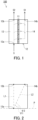
- FIG. 1 is a schematic cross-sectional view showing an example of a membrane separation device 100 of the present embodiment.
- the membrane separation device 100 includes: a pervaporation membrane 11 that separates a fermented liquid S containing a volatile organic compound into a permeated fluid S1 and a non-permeated fluid S2; a feed space 13 and a permeation space 14 separated from each other by the pervaporation membrane 11; a feed space inlet 13a for supplying the fermented liquid S to the feed space 13; and a feed space outlet 13b for discharging the non-permeated fluid S2 from the feed space 13.
- the feed space inlet 13a is positioned below the feed space outlet 13b.
- the membrane separation device 100 is a device that performs membrane separation, during its operation, for the fermented liquid S containing a volatile organic compound by using the pervaporation membrane 11.
- the feed space inlet 13a is positioned below the feed space outlet 13b in the membrane separation device 100.
- This makes it possible to introduce the fermented liquid S to the membrane separation device 100 in such a manner that the fermented liquid S flows from a lower side to an upper side inside the membrane separation device 100.
- formation of a local dried solidified area and stagnation of the fermented liquid S inside the membrane separation device 100 due to a factor such as variation in the amount of the fermented liquid S to be supplied to the membrane separation device 100 tend to be avoided. Accordingly, the growth of an undesirable microorganism inside the membrane separation device 100 is suppressed.
- the membrane separation device 100 further includes a casing 12. Inside the casing 12, the feed space 13 and the permeation space 14 are provided.
- the feed space 13 functions as a feed space to which the fermented liquid S is supplied.
- the permeation space 14 functions as a permeation space to which the permeated fluid S1 is supplied.
- the permeated fluid S1 is obtained by allowing the fermented liquid S to permeate through the pervaporation membrane 11.
- the pervaporation membrane 11 is disposed inside the casing 12. Inside the casing 12, the pervaporation membrane 11 separates the feed space 13 and the permeation space 14 from each other.
- the pervaporation membrane 11 extends from one of a pair of wall surfaces of the casing 12 to the other.
- the membrane separation device 100 further includes a permeation space outlet 14b for discharging the permeated fluid S1 from the permeation space 14.
- the permeation space outlet 14b may be positioned above the feed space inlet 13a. Such a configuration makes it possible to recover easily the permeated fluid S1 that is a gas and that has been discharged from the membrane separation device 100.
- the permeation space outlet 14b may be positioned at the same height as that of the feed space outlet 13b.
- the permeation space outlet 14b may be positioned at the same height as that of the feed space inlet 13a, or may be positioned below the feed space inlet 13a. Such a configuration makes it possible to recover easily the permeated fluid S1 even when the permeated fluid S1 discharged from the membrane separation device 100 is liquefied.
- the permeation space outlet 14b may be positioned below the feed space outlet 13b.
- the feed space 13 communicates with the feed space inlet 13a and the feed space outlet 13b.
- the permeation space 14 communicates with the permeation space outlet 14b.
- the feed space inlet 13a is an opening for supplying the fermented liquid S to the membrane separation device 100.
- the permeation space outlet 14b is an opening for discharging the permeated fluid S1 from the membrane separation device 100.
- the feed space outlet 13b is an opening for discharging, from the membrane separation device 100, the fermented liquid S (a non-permeated fluid S2) not having permeated through the pervaporation membrane 11.
- the feed space inlet 13a, the feed space outlet 13b, and the permeation space outlet 14b are formed, for example, in wall surfaces of the casing 12.
- the feed space inlet 13a may be formed in a lower face of the casing 12, and the feed space outlet 13b and the permeation space outlet 14b may be formed in an upper face of the casing 12.
- the feed space inlet 13a may be formed in a side face of the casing 12.
- the feed space outlet 13b may be formed in the side face of the casing 12.
- the permeation space outlet 14b may be formed in the side face of the casing 12.
- a shape of the casing 12 is not particularly limited as long as the fermented liquid S can be introduced in such a manner as to flow from the lower side to the upper side inside the membrane separation device 100.
- the casing 12 may have a prismatic shape or a cylindrical shape, for example. As shown in FIG. 1 , in the case where the casing 12 has a longitudinal direction, the casing 12 may be placed in such a manner that the longitudinal direction extends from the lower side to the upper side. The casing 12 may be placed vertically so that the longitudinal direction is along a vertical direction.
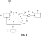
- FIG. 2 is a diagram for explaining a tilt angle in the membrane separation device 100 of the present embodiment.
- a tilt angle of a virtual straight line L1 connecting the feed space inlet 13a to the feed space outlet 13b with respect to a level surface P is defined as ⁇ 1.
- ⁇ 1 refers to a smallest angle between the virtual straight line L1 and the level surface P within a range from 0° or more to 90° or less.
- the virtual straight line L1 can be defined as a virtual straight line connecting a center point of the feed space inlet 13a to a center point of the feed space outlet 13b.
- ⁇ 1 is 5° or more and 90° or less, for example. According to such a structure, formation of a local dried solidified area and stagnation of the fermented liquid S inside the membrane separation device 100 are likely to be avoided.
- ⁇ 1 may be 10° or more, 15° or more, 25° or more, 35° or more, 45° or more, 55° or more, or 65° or more. ⁇ 1 may be 75° or more and 90° or less. That is, ⁇ 1 may satisfy 75° ⁇ ⁇ 1 ⁇ 90°.
- a tilt angle of a virtual straight line L2 connecting the feed space inlet 13a to the permeation space outlet 14b with respect to the level surface P is defined as ⁇ 2.
- ⁇ 2 refers to a smallest angle between the virtual straight line L2 and the level surface P within a range from 0° or more to 90° or less.
- the virtual straight line L2 can be defined as a virtual straight line connecting the center point of the feed space inlet 13a to a center point of the permeation space outlet 14b.
- ⁇ 2 may be 5° or more, 15° or more, 25° or more, or 35° or more. ⁇ 2 may be 45° or more and 90° or less. That is, ⁇ 2 may satisfy 45° ⁇ ⁇ 2 ⁇ 90°.
- ⁇ 2 may be 50° or more, 55° or more, or 60° or more.
- the tilt angle ⁇ 2 may be substantially 75°.
- the membrane separation device 100 may separate the fermented liquid S into the permeated fluid S1 and the non-permeated fluid S2 in a state in which the feed space 13 is filled with the fermented liquid S.
- the membrane separation device 100 is suitable for a flow-type (continuous-type) membrane separation method. However, the membrane separation device 100 may be used for a batch-type membrane separation method.
- FIG. 3 is a schematic cross-sectional view of the pervaporation membrane 11 included in the membrane separation device 100.
- the pervaporation membrane 11 includes, for example, a separation functional layer 1 and a porous support member 2 supporting the separation functional layer 1.
- the pervaporation membrane 11 may further include a protective layer (not shown) that protects the separation functional layer 1.
- the separation functional layer 1 is in direct contact with the porous support member 2, for example.
- the pervaporation membrane 11 has a principal surface 11a, on the separation functional layer side, that is exposed to the feed space 13 and a principal surface 11b, on the porous support member side, that is exposed to the permeation space 14.
- the pervaporation membrane 11 is a membrane (a concentration membrane) that allows the organic compound contained in the fermented liquid S to preferentially permeate therethrough.
- a content of the organic compound in the permeated fluid S1 is higher than a content of the organic compound in the fermented liquid S.
- a content of the organic compound in the non-permeated fluid S2 is lower than the content of the organic compound in the fermented liquid S.
- the separation functional layer 1 is a layer that allows the organic compound contained in the fermented liquid S to preferentially permeate therethrough.
- the separation functional layer 1 includes a hydrophobic material, for example.
- hydrophobic material refers to, for example, a material that has a static contact angle exceeding 90° with respect to water when a 10 ⁇ L drop of the water (temperature 25°C) is dropped on a surface of a specimen composed of the material. Note that the static contact angle with respect to water can be measured using a commercially available contact angle meter.
- hydrophobic material examples include a compound having a siloxane bond (a Si-O-Si bond), an olefin-based polymer, an oil, and a fluorine-based compound.
- the separation functional layer 1 preferably includes a compound having a siloxane bond as the hydrophobic material.
- the compound having a siloxane bond is typically a silicone resin.
- the silicone resin may be a solid or a liquid at 25°C.
- Specific examples of the silicone resin include polydimethylsiloxane (PDMS).
- Specific examples of the olefin-based polymer include polyethylene and polypropylene.
- the oil examples include a hydrocarbon-based oil such as liquid paraffin.
- fluorine-based compound examples include polytetrafluoroethylene (PTFE), polyvinylidene fluoride (PVDF), and tetrafluoroethylene-perfluoroalkyl vinyl ether copolymer (PFA). These hydrophobic materials can be used alone or two or more of them can be used in combination.
- PTFE polytetrafluoroethylene
- PVDF polyvinylidene fluoride
- PFA tetrafluoroethylene-perfluoroalkyl vinyl ether copolymer
- the separation functional layer 1 may include a silicone resin.
- the pervaporation membrane 11 that includes the separation functional layer 1 including a silicone resin is suitably used for concentrating the organic compound contained in the fermented liquid S.
- the separation functional layer 1 may include the hydrophobic material as a main component, or may be composed substantially of the hydrophobic material alone.
- the term "main component” means a component having a largest content in the separation functional layer 1 in terms of weight ratio.
- the separation functional layer 1 may include a matrix including the hydrophobic material and a filler dispersed in the matrix.
- the filler is buried in the matrix. In the matrix, all particles of the filler may be spaced from each other or may aggregate partially.
- the filler includes, for example, an inorganic material such as zeolite, silica, or bentonite.
- the zeolite included in the filler is preferably a high-silica zeolite having a high ratio of silica with respect to alumina. Having high resistance to hydrolysis, the high-silica zeolite is suitably used for separating the aqueous solution S.
- high-silica zeolite to be used examples include HSZ (registered trademark) available from Tosoh Corporation, HiSiv (registered trademark) available from UNION SHOWA K.K., USKY available from UNION SHOWA K.K., and Zeoal (registered trademark) available from Nakamura Choukou Co., Ltd.
- the filler may include a metal organic framework (MOF).
- the metal organic framework is also referred to as a porous coordination polymer (PCP).
- the metal organic framework is preferably hydrophobic.
- the metal organic framework includes a metal ion and an organic ligand, for example. Examples of the metal ion include a Zn ion.
- the organic ligand includes an aromatic ring, for example. Examples of the aromatic ring included in the organic ligand include an imidazole ring. Examples of the organic ligand include 2-methylimidazole. Specific examples of the metal organic framework include ZIF-8.
- the filler is in the form of particles, for example.
- the term "form of particles" herein includes spherical, elliptical, flaky, and fibrous forms.
- An average particle diameter of the filler is, for example, but not particularly limited to, 50 ⁇ m or less, preferably 20 ⁇ m or less, and more preferably 10 ⁇ m or less.
- the lower limit of the average particle diameter of the filler is 0.01 ⁇ m, for example.
- the average particle diameter of the filler can be determined by the following method, for example. First, a cross-section of the separation functional layer 1 is observed using a transmission electron microscope. The area of a specific particle of the filler on the resulting electron microscope image is calculated by image processing.
- the diameter of a circle having the same area as the calculated area is regarded as the particle diameter (the diameter of the particle) of the specific filler particle.
- the particle diameter was calculated for any number (at least 50) of the filler particles, and the average of the calculated values was regarded as the average particle diameter of the filler.
- a content of the filler in the separation functional layer 1 that includes the matrix including the hydrophobic material is, for example, 10 wt% or more, preferably 30 wt% or more, and more preferably 40 wt% or more.
- the upper limit of the content of the filler in the separation functional layer 1 is, for example, but not particularly limited to, 70 wt%.
- a content of the matrix in the separation functional layer 1 is, for example, but not particularly limited to, 30 wt% to 90 wt%.
- the separation functional layer 1 has a thickness of, for example, 200 ⁇ m or less, preferably 100 ⁇ m or less, and more preferably 80 ⁇ m or less.
- the separation functional layer 1 may have a thickness of 1.0 ⁇ m or more, 10 ⁇ m or more, or 30 ⁇ m or more.
- the separation functional layer 1 may have a microporous structure with an average pore diameter of less than 0.01 ⁇ m, but may be a dense layer having no pore on its surface.
- porous support member 2 examples include: a nonwoven fabric; porous polytetrafluoroethylene; aromatic polyamide fiber; a porous metal; a sintered metal; porous ceramic; porous polyester; porous nylon; activated carbon fiber; latex; silicone; silicone rubber; a permeable (porous) polymer including at least one selected from the group consisting of polyvinyl fluoride, polyvinylidene fluoride, polyurethane, polypropylene, polyethylene, polystyrene, polycarbonate, polysulfone, polyether ether ketone, polyacrylonitrile, polyimide, and polyphenylene oxide; a metallic foam having an open cell or a closed cell; a polymer foam having an open cell or a closed cell; silica; a porous glass; and a mesh screen.
- the porous support member 2 may be a combination of two or more of these materials.
- the porous support member 2 has an average pore diameter of 0.01 to 0.4 ⁇ m, for example.
- a thickness of the porous support 2 is, for example, but not particularly limited to, 10 ⁇ m or more, preferably 50 ⁇ m or more, and more preferably 100 ⁇ m or more.
- the thickness of the porous support 2 is, for example, 300 ⁇ m or less, and preferably 200 ⁇ m or less.
- the protective layer covers a surface of the separation functional layer 1, for example.
- a material of the protective layer is, for example, but not particularly limited to, a silicone resin.
- the material of the protective layer may be the same as or different from that of the matrix of the separation functional layer 1.
- a thickness of the protective layer is, for example, but not particularly limited to, 0.5 ⁇ m or more, preferably 1 ⁇ m or more, more preferably 5 ⁇ m or more, and still more preferably 10 ⁇ m or more.
- the thickness of the protective layer is, for example, 100 ⁇ m or less, preferably 50 ⁇ m or less, and more preferably 30 ⁇ m or less.
- the pervaporation membrane 11 can be produced by, for example, forming the separation functional layer 1 on the porous support member 2. Specifically, a coating liquid containing the materials of the separation functional layer 1 is prepared first.
- the coating liquid may contain, in addition to the filler, a dispersant for dispersing the filler in the coating liquid.
- the coating liquid may further contain a catalyst for curing the compound.
- the coating liquid is applied onto the porous support 2 to obtain a coating. The coating is dried to obtain the separation functional layer 1.
- the pervaporation membrane 11 can be obtained.
- the pervaporation membrane 11 is a membrane (a dehydration membrane) that allows water contained in the fermented liquid S to preferentially permeate therethrough.
- the pervaporation membrane 11 is a dehydration membrane
- the content of the organic compound in the permeated fluid S1 is lower than the content of the organic compound in the fermented liquid S.
- the content of the organic compound in the non-permeated fluid S2 is higher than the content of the organic compound in the fermented liquid S.
- the separation functional layer 1 is a layer that allows water contained in the fermented liquid S to preferentially permeate therethrough.
- the separation functional layer 1 may include at least one selected from the group consisting of polyimide and zeolite. Zeolite has high hydrophilicity. Polyimide is a material that can better suppress swelling with water than zeolite. Specific examples of the zeolite include crystalline silicate such as silicalite-1 or silicalite-2, and crystalline titanosilicate such as TS-1.
- the pervaporation membrane 11 that includes the separation functional layer 1 including at least one selected from the group consisting of polyimide and zeolite is suitable for removing water contained in the fermented liquid S, that is, suitably used for dehydration.
- the separation functional layer 1 may include polyimide as a main component, or may be composed substantially of polyimide alone.
- the separation functional layer 1 may include zeolite as a main component, or may be composed substantially of zeolite alone.
- the separation functional layer 1 may include a matrix including at least one selected from the group consisting of polyimide and zeolite, and a filler dispersed in the matrix.
- the filler is buried in the matrix. In the matrix, all particles of the filler may be spaced from each other or may aggregate partially.
- the filler the one mentioned as usable for the separation functional layer 1 in the case where the pervaporation membrane 11 is a concentration membrane can be used.
- a content of the filler in the separation functional layer 1 that includes the matrix including at least one selected from the group consisting of polyimide and zeolite is, for example, 10 wt% or more, preferably 30 wt% or more, and more preferably 40 wt% or more.
- the upper limit of the content of the filler in the separation functional layer 1 is, for example, but not particularly limited to, 70 wt%.
- a content of the matrix in the separation functional layer 1 is, for example, but not particularly limited to, 30 wt% to 90 wt%.
- the separation functional layer 1 has a thickness of, for example, 200 ⁇ m or less, preferably 100 ⁇ m or less, and more preferably 80 ⁇ m or less.
- the separation functional layer 1 may have a thickness of 1.0 ⁇ m or more, 10 ⁇ m or more, and 30 ⁇ m or more.
- the separation functional layer 1 may have a microporous structure with an average pore diameter of less than 0.01 ⁇ m, but may be a dense layer having no pore on its surface.
- porous support member 2 the one mentioned as the porous support member 2 in the case where the pervaporation membrane 11 is a concentration membrane can be used.
- the protective layer the one mentioned as the protective layer in the case where the pervaporation membrane 11 is a concentration membrane can be used.
- the pervaporation membrane 11 can be produced by the same method as that used in the case where the pervaporation membrane 11 is a concentration membrane.
- a method for operating the membrane separation device 100 includes: supplying the fermented liquid S to the membrane separation device 100 from the feed space inlet 13a; and separating the fermented liquid S into the permeated fluid S1 and the non-permeated fluid S2 with the pervaporation membrane 11. According to the method for operating the membrane separation device 100, formation of a local dried solidified area and stagnation of the fermented liquid S inside the membrane separation device 100 due to a factor such as variation in the amount of the fermented liquid S to be supplied to the membrane separation device 100 are avoided. Accordingly, the growth of an undesirable microorganism inside the membrane separation device 100 is suppressed.
- the method for operating the membrane separation device 100 is carried out as follows, for example.
- the fermented liquid S is supplied to the feed space 13 of the membrane separation device 100 from the lower side to the upper side via the feed space inlet 13a positioned below the feed space outlet 13b. This makes it possible to bring the fermented liquid S into contact with one surface (the principal surface 11a, for example) of the pervaporation membrane 11.
- the fermented liquid S contains, for example, the organic compound as a fermented product, and water.
- the organic compound contained in the fermented liquid S is not particularly limited as long as the organic compound has volatility.
- the term "organic compound having volatility" refers to an organic compound that has a boiling point of 20 to 260°C, preferably 50°C to 260°C, under an atmospheric pressure (101.325 kPa). Note that the organic compound allows, for example, an aqueous phase containing water as a main component and an organic phase having a content of the organic compound higher than that in the aqueous phase to be generated when a concentration of the organic compound is high in the aqueous solution.
- the number of carbon atoms in the organic compound is, for example, but not particularly limited to, 10 or less, and may be 8 or less, 6 or less, or even 4 or less.
- the lower limit of the number of carbon atoms in the organic compound may be 1 or 2.
- the organic compound has, for example, a functional group including an oxygen atom, such as a hydroxyl group, a carbonyl group, an ether group, and an ester group. In the organic compound, the number of the functional groups including an oxygen atom is typically one.
- the organic compound examples include an alcohol, ketone, and ester.
- the organic compound is likely to be compatible with water and thus unlikely to cause unevenness in an environment in its system.
- the alcohol may be an alkyl alcohol composed only of an alkyl group and a hydroxyl group, or may be an aryl alcohol including an aryl group and a hydroxyl group.
- the alkyl alcohol may be linear, branched, or cyclic.
- alkyl alcohol examples include methanol, ethanol, n-propanol, isopropanol, n-butanol (BuOH), 2-butanol, isobutanol, t-butanol, and n-pentanol, and preferred is n-butanol.
- N-butanol is a compound that allows two phases (an aqueous phase and an organic phase) to be generated from an aqueous solution thereof when a content of the compound in the aqueous solution is around 8 wt% or more.
- the organic compound is n-butanol
- the content of the organic compound in the permeated fluid it is possible, by adjusting the content of the organic compound in the permeated fluid to be around 8 wt% or more, for example, to generate an aqueous phase and an organic phase in the permeated fluid after the permeated fluid is liquefied.
- the aryl alcohol include phenol.
- the ketone may be dialkylketone composed only of an alkyl group and a carbonyl group.
- Examples of the dialkylketone as the organic compound include methyl ethyl ketone (MEK) and acetone.
- the ester may be aliphatic alkylester composed only of an alkyl group and an ester group.
- Examples of the aliphatic alkylester include ethyl acetate.
- organic compound is not limited to those mentioned above.
- the organic compound may be aromatic hydrocarbon such as benzene, toluene, or xylene.
- the fermented liquid S may contain one kind of the organic compound, or two or more kinds of the organic compounds.
- the content of the organic compound in the fermented liquid S is, for example, 50 wt% or less, and may be 30 wt% or less, 10 wt% or less, 5 wt% or less, 2 wt% or less, or even 1 wt% or less.
- the lower limit of the content of the organic compound is, for example, but not particularly limited to, 0.01 wt%.
- the organic compound is a fermented product generated by fermentation of a carbon source by a microorganism. That is, in the present embodiment, the fermented liquid S is a fermented liquid containing the organic compound as the fermented product.
- the fermented liquid S may further contain, other than water and the organic compound, an additional component, such as a microorganism associated with the generation of the fermented product, a carbon source, a nitrogen source, or an inorganic ion.
- an additional component such as a microorganism associated with the generation of the fermented product, a carbon source, a nitrogen source, or an inorganic ion.
- the microorganism associated with the generation of the fermented product is typically a bacterium.
- the carbon source include polysaccharides such as starch, and monosaccharides such as glucose.
- the amount of the fermented liquid S to be supplied to the membrane separation device 100 is not particularly limited and is determined according to the processing capacity of the membrane separation device 100.
- the fermented liquid S to be supplied to the feed space 13 may be heated in advance.
- the fermented liquid S to be supplied to the feed space 13 has a temperature of 15°C to 75°C.
- a space adjacent to another surface (the principal surface 11b, for example) of the pervaporation membrane 11 is decompressed.
- an inside of the permeation space 14 is decompressed via the permeation space outlet 14b.
- the inside of the permeation space 14 can be decompressed by, for example, a decompression device such as a vacuum pump.
- a pressure in the permeation space 14 is, for example, 50 kPa or less, and may be 20 kPa or less, 10 kPa or less, 5 kPa or less, 3 kPa or less, or even 2 kPa or less.
- the term "pressure" means an absolute pressure unless otherwise noted.
- the pervaporation membrane 11 is a concentration membrane
- decompressing the inside of the permeation space 14 makes it possible to obtain, on the side of the other surface of the pervaporation membrane 11, the permeated fluid S1 having a high content of the organic compound.
- the permeated fluid S1 is supplied to the permeation space 14.
- the permeated fluid S1 is discharged outside the membrane separation device 100 via the permeation space outlet 14b.
- the permeated fluid S1 that is a gas is cooled in a condensation unit, etc., for example. Thereby, the permeated fluid S1 is liquefied to obtain the permeated fluid S1 that is a liquid.
- the pervaporation membrane 11 is a concentration membrane
- the content of the organic compound in the fermented liquid S gradually decreases from the feed space inlet 13a toward the feed space outlet 13b in the feed space 13.
- the fermented liquid S (the non-permeated fluid S2) processed in the feed space 13 is discharged outside the first membrane separation device 100 via the feed space outlet 13b.
- the non-permeated fluid S2 is typically a liquid.
- the pervaporation membrane 11 of the membrane separation device 100 allows the organic compound contained in the fermented liquid S to preferentially permeate therethrough. Accordingly, the permeated fluid S1 obtained by the operation of the membrane separation device 100 has a content of the organic compound higher than that in the fermented liquid S to be supplied to the membrane separation device 100.
- a washing operation for the membrane separation device 100 may be executed after the operation of membrane separation is executed for a certain period of time according to the above method for operating the membrane separation device 100.
- the washing operation for the membrane separation device 100 may be executed regularly.
- the operating method of the present embodiment makes it possible, for example, to produce the permeated fluid S1 having a high content of the organic compound.
- the operating method of the present embodiment makes it possible to produce the organic compound as the permeated fluid S1.
- the present invention provides a method for producing an organic compound, including:
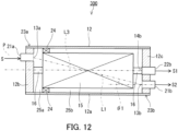
- FIG. 4A is a schematic cross-sectional view showing Modification 1 of the membrane separation device 100 of the present embodiment.
- a membrane separation device 101 of Modification 1 includes a membrane element 15 having the pervaporation membrane 11.
- the membrane element 15 is disposed inside the casing 12.
- the feed space inlet 13a is positioned below the feed space outlet 13b.
- the membrane element 15 may be a spiral membrane element, a hollow fiber membrane element, a disk tube membrane element in which a plurality of pervaporation membranes are laminated, a plate-and-flame membrane element, or the like.
- the membrane element 15 is typically a spiral membrane element.
- FIG. 4A shows an example in the case where the membrane element 15 is a spiral membrane element.
- FIG. 5 is a developed perspective view showing schematically a spiral membrane element.
- the membrane element 15 may be a spiral membrane element as shown in FIG. 5 .
- the spiral membrane element 15 in FIG. 5 has a central tube 16 and the pervaporation membrane 11, and includes a membrane leaf 17 that is wound around the central tube 16.
- the central tube 16 extends from the lower side to the upper side.
- the central tube 16 may extend in the vertical direction.
- the central tube 16 has a cylindrical shape.
- the central tube 16 has a surface with a through hole 16h formed therein to allow the permeated fluid S1 to flow into the central tube 16.
- the number of the through holes 16h is not particularly limited and may be one, or two or more.
- Examples of a material of the central tube 16 include: a resin such as an acrylonitrile-butadiene-styrene copolymer resin (an ABS resin), a polyphenylene ether resin (a PPE resin), or a polysulfone resin (a PSF resin); and a metal such as stainless steel or titanium.
- the central tube 16 has an inner diameter in a range of, for example, 20 to 100 mm.
- the membrane element 15 has a plurality of the membrane leaves 17.
- Each of the membrane leaves 17 further includes the pervaporation membrane 11 and a permeation-side flow passage material 19.
- each of the membrane leaves 17 has two pieces of the pervaporation membranes 11.
- the two pieces of the pervaporation membranes 11 are stacked with each other and sealed on three sides in such a manner as to have a bag-like structure.
- the permeation-side flow passage material 19 is disposed between the two pieces of the pervaporation membranes 11 in such a manner as to be positioned inside the bag-like structure.
- the permeation-side flow passage material 19 secures, between the two pieces of the pervaporation membranes 11, a space (a permeation space) serving as a flow passage for the permeated fluid S1.
- the permeation-side flow passage material 19 is combined with the pervaporation membrane 11 and used.
- the number of the membrane leaves 17 is, for example, but not particularly limited to, 2 to 30.
- the membrane element 15 further has a feed-side flow passage material 18.
- the feed-side flow passage material 18 is positioned outside the above-mentioned bag-like structure and is laminated on the membrane leaf 17. Specifically, a plurality of the feed-side flow passage materials 18 and a plurality of the membrane leaves 17 are laminated alternately.
- the feed-side flow passage material 18 secures, between the membrane leaf 17 and the membrane leaf 17, a space (a feed space) serving as a flow passage for the fermented liquid S.
- a resin net, woven fabric, or knitted fabric composed of polyethylene, polypropylene, polyethylene terephthalate (PET), polyphenylene sulfide (PPS), or an ethylene-chlorotrifluoroethylene copolymer (ECTFE) can be used, for example.
- PET polyethylene terephthalate
- PPS polyphenylene sulfide
- ECTFE ethylene-chlorotrifluoroethylene copolymer
- the casing 12 has a casing main body 12a, a first end plate 12b, and a second end plate 12c.
- the casing main body 12a has a cylindrical shape and is made from a material having sufficient pressure resistance.
- the first end plate 12b is attached to a lower-side end portion 23a of the casing 12.
- the end portion 23a of the casing 12 is closed with the first end plate 12b.
- the second end plate 12c is attached to an upper-side end portion 23b of the casing 12.
- the end portion 23b of the casing 12 is closed with the second end plate 12c.
- the casing 12 has a port 21a, a port 21b, and a port 22b. These ports are ports for allowing an inside of the casing 12 to communicate with an outside of the casing 12.
- the port 21a is provided at the lower-side end portion 23a of the casing 12.
- the port 21b and the port 22b are provided at the upper-side end portion 23b of the casing 12.
- the port 21a may be provided to the first end plate 12b, and the port 22b may be provided to the second end plate 12c.
- the port 21b and the port 22b may be provided to the second end plate 12c.
- the feed space inlet 13a communicates with the port 21a, and the port 21a is used as an inlet for the fermented liquid S.
- the central tube 16 is connected to the port 22b at the permeation space outlet 14b. That is, the port 22b is used as an outlet for the permeated fluid S1.
- the feed space outlet 13b communicates with the port 21b, and the port 21b is used as an outlet for the non-permeated fluid S2.
- Each of the ports may be a simple opening, or a nozzle-like opening as shown in FIG. 4 .
- the membrane separation device 101 further includes a sealing member 24 disposed in a space between the membrane element 15 and the casing 12.
- the sealing member 24 has a ring shape and surrounds the membrane element 15 in a circumferential direction.
- the sealing member 24 is disposed on a lower end side of the membrane element 15.
- the sealing member 24 divides an inner space of the casing 12 into a space 25a and a space 25b.
- the space 25a is positioned below the space 25b.
- a tilt angle of a center axis L3 of the membrane element 15 with respect to the level surface P is defined as ⁇ 3.
- ⁇ 3 refers to a smallest angle between the center axis L3 and the level surface P within a range from 0° or more to 90° or less.
- the center axis L3 can be defined as a center axis of the central tube 16.
- ⁇ 3 may be 5° or more, 15° or more, 25° or more, or 35° or more. ⁇ 3 may be 45° or more and 90° or less. That is, ⁇ 3 may satisfy 45° ⁇ ⁇ 3 ⁇ 90°. According to such a structure, formation of a local dried solidified area and stagnation of the fermented liquid S inside the membrane separation device 100 are likely to be avoided.
- ⁇ 3 may be 50° or more, 55° or more, 60° or more, 65° or more, or 70° or more.
- ⁇ 1 is 35° or more and 90° or less. As shown in FIG. 4A , ⁇ 1 may satisfy 35° ⁇ ⁇ 1 ⁇ 90°.
- ⁇ 2 is 55° or more and 90° or less. As shown in FIG. 4A , ⁇ 2 may satisfy 55° ⁇ ⁇ 2 ⁇ 90°.
- ⁇ 3 is substantially 90°. As shown in FIG. 4A , ⁇ 3 may be substantially 90°.
- ⁇ 1 may satisfy 35° ⁇ ⁇ 1 ⁇ 90° and ⁇ 3 may be substantially 90°.
- an end portion member which is not shown, may be attached to one end or each of both ends, in an axial direction, of the membrane element 15.
- the end portion member is also referred to as a telescope prevention member, an anti-telescope material, and the like.
- the sealing member 24 is provided via the end portion member disposed at an upstream-side end portion of the membrane element 15.
- the membrane element 15 may have a diameter of 8 inches (approximately 201 mm) or less.
- the membrane separation device 101 including the membrane element 15 in such a size has excellent transportability.
- a method for operating the membrane separation device 101 is carried out as follows, for example.
- the fermented liquid S is supplied from the port 21a (the feed space inlet 13a), and a space inside the central tube 16 is decompressed.
- the permeated fluid S1 having permeated through the pervaporation membrane 11 of the membrane leaf 17 thereby moves into the central tube 16.
- the permeated fluid S1 is discharged outside from the port 22b (the permeation space outlet 14b) via the central tube 16.
- the fermented liquid S (the non-permeated fluid S2) processed by the membrane element 15 is discharged outside from the port 21b (the feed space outlet 13b).
- FIG. 4B is a schematic cross-sectional view showing another example of Modification 1.
- a membrane separation device 111 shown in FIG. 4B has the same configuration as that of the membrane separation device 101 shown in FIG. 4A , except that the tilt angles ( ⁇ 1, ⁇ 2, 83) are different. Therefore, the elements common between the membrane separation device 101 and the membrane separation device 111 are denoted by the same reference numerals, and the description of such elements may be omitted.
- the tilt angle ⁇ 1 of the virtual straight line L1 connecting the feed space inlet 13a to the feed space outlet 13b with respect to the level surface P is more than 0° and less than 90°.
- ⁇ 1 may satisfy 0° ⁇ ⁇ 1 ⁇ 90°. According to such a structure, formation of a local dried solidified area and stagnation of the fermented liquid S inside the membrane separation device 111 are more likely to be avoided.
- the tilt angle ⁇ 2 of the virtual straight line L2 connecting the feed space inlet 13a to the permeation space outlet 14b with respect to the level surface P is more than 0° and less than 90°.
- ⁇ 2 may satisfy 0° ⁇ ⁇ 2 ⁇ 90°.
- 81 and ⁇ 2 may satisfy ⁇ 1 > ⁇ 2.
- the feed space outlet 13b is positioned above the permeation space outlet 14b. According to such a structure, formation of a local dried solidified area and stagnation of the fermented liquid S inside the membrane separation device 100 are likely to be avoided.
- the tilt angle ⁇ 3 of the center axis L3 of the membrane element 15 with respect to the level surface P is more than 0° and less than 90°. As shown in FIG. 4B , ⁇ 3 may satisfy 0° ⁇ ⁇ 3 ⁇ 90°.
- FIG. 4C is a schematic cross-sectional view showing still another example of Modification 1.
- a membrane separation device 121 shown in FIG. 4C has the same configuration as that of the membrane separation device 101 shown in FIG. 4A , except that the tilt angles ( ⁇ 1, ⁇ 2, 83) are different. Therefore, the elements common between the membrane separation device 101 and the membrane separation device 121 are denoted by the same reference numerals, and the description of such elements may be omitted.
- the tilt angle ⁇ 1 of the virtual straight line L1 connecting the feed space inlet 13a to the feed space outlet 13b with respect to the level surface P is more than 0° and 55° or less.
- ⁇ 1 may satisfy 0° ⁇ ⁇ 1 ⁇ 55°. According to such a structure, formation of a local dried solidified area and stagnation of the fermented liquid S inside the membrane separation device 121 are also avoided to a certain extent.
- the tilt angle ⁇ 2 of the virtual straight line L2 connecting the feed space inlet 13a to the permeation space outlet 14b with respect to the level surface P is 0° or more and 35° or less. As shown in FIG. 4C , ⁇ 2 may satisfy 0° ⁇ ⁇ 2 ⁇ 35°.
- the tilt angle ⁇ 3 of the center axis L3 of the membrane element 15 with respect to the level surface P is substantially 0°. As shown in FIG. 4C , ⁇ 3 may be substantially 0°.
- Each membrane separation device of the present embodiment mentioned above may be used in such a manner that a plurality thereof are connected to each other in series.
- the membrane separation device 111 shown in FIG. 4B and the membrane separation device 121 shown in FIG. 4C are more practical than the membrane separation device 101 shown in FIG. 4A in that they are easy to connect and install.
- the membrane separation device 121 shown in FIG. 4C is even easier to connect and install than the membrane separation device 111 shown in FIG. 4B .
- the membrane separation device 101 shown in FIG. 4A can charge an even larger amount of a liquid into the membrane element than the membrane separation device 111 shown in FIG. 4B . That is, the membrane separation device 101 shown in FIG. 4A is highly effective in suppressing an increase of the local dried solidified area inside the membrane separation device.
- the membrane separation device 121 shown in FIG. 4C is highly practical.
- the membrane separation device 111 shown in FIG. 4B has an excellent balance between the practicality and the effectiveness in suppressing an increase of the local dried solidified area inside the membrane separation device.
- the membrane separation devices of the present embodiment mentioned above can also be used in combination and connected to each other in series.
- FIG. 6 is a schematic cross-sectional view showing Modification 2 of the membrane separation device 100 of the present embodiment.
- a membrane separation device 102 of Modification 2 has the same configuration as that of the membrane separation device 101 of Modification 1, except that the membrane separation device 102 further includes a fluid discharge outlet 26 connected to the feed space 13 and the fluid discharge outlet 26 is positioned below the feed space outlet 13b. Therefore, the elements common between the above-mentioned membrane separation device 101 and the membrane separation device 102 of Modification 2 are denoted by the same reference numerals, and the description of such elements may be omitted.
- a fluid S4 flows into the inner space (especially the space 25a) of the casing 12 and stagnates therein in some cases.
- the fluid S4 is, for example, a washing liquid used at the time of washing the membrane separation device 102.
- the membrane separation device 102 can discharge the above fluid S4 from the fluid discharge outlet 26. During operation, it is also possible to discharge the fermented liquid S, etc. stagnated in the inner space of the casing 12 from the discharge outlet 26 as necessary.
- the fluid discharge outlet 26 may be positioned on the same side as that the feed space inlet 13a is on with respect to an axial direction of the central tube 16. As shown in FIG. 6 , both of the fluid discharge outlet 26 and the feed space inlet 13a may be provided to the first end plate 12b.
- the casing 12 further has a port 27.
- the port 27 is a port for allowing the inside of the casing 12 to communicate with the outside of the casing 12.
- the port 27 is provided at the lower-side end portion 23a of the casing 12.
- the port 27 may be provided to the second end plate 12b.
- the fluid discharge outlet 26 communicates with the port 27, and the port 27 is used as an outlet for the fluid S4.
- the port 27 may be a simple opening, or a nozzle-like opening as shown in FIG. 6 .
- FIG. 6 is an example in the case where the fluid discharge outlet 25 is provided in addition to the permeation space outlet 13a.
- the permeation space outlet 13a may also serve as the fluid discharge outlet 25. That is, the configuration may be made in such a manner that the fluid S4 can be discharged from the permeation space outlet 13a.
- FIG. 7 is a schematic cross-sectional view showing Modification 3 of the membrane separation device 100 of the present embodiment.
- a membrane separation device 103 of Modification 3 has the same configuration as that of the membrane separation device 102 of Modification 2, except that the first end plate 12b of the casing 12 has a cone shape or a truncated cone shape protruding toward the outside of the casing 12. Therefore, the elements common between the above-mentioned membrane separation device 102 and the membrane separation device 103 of Modification 3 are denoted by the same reference numerals, and the description of such elements may be omitted.
- the membrane separation device 103 makes it easy for the fluid S4 to be discharged from the fluid discharge outlet 26.
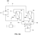
- FIG. 8 is a schematic configuration diagram showing an example of a membrane separation system 1000 of Embodiment 1.
- the membrane separation system 1000 of the present embodiment includes the above-mentioned membrane separation device 100, 101, 111, 121, 102 or 103 as the membrane separation device.
- the membrane separation device 100, 101, 111, 121, 102 or 103 is collectively referred to as the membrane separation device 100 for convenience.
- the membrane separation system 1000 can carry out the above-mentioned operating method for the membrane separation device 100.
- the pervaporation membrane 11 is a membrane (a concentration membrane) that allows the organic compound contained in the fermented liquid S to preferentially permeate therethrough.
- the membrane separation system 1000 further includes a tank 30 in addition to the membrane separation device 100.
- the tank 30 stores the fermented liquid S to be supplied to the membrane separation device 100.
- the tank 30 is typically a fermenter for generating the organic compound by fermentation of a carbon source by a microorganism.
- the membrane separation system 1000 may further include a decompression device 40.
- the decompression device 40 can decompress the inside of the permeation space 14 of the membrane separation device 100.
- the decompression device 40 is a vacuum device such as a vacuum pump.
- the vacuum pump is typically a gas transport vacuum pump, and a reciprocating vacuum pump and a rotary vacuum pump, etc. can be mentioned.
- Examples of the reciprocating vacuum pump include a diaphragm vacuum pump and a rocking piston vacuum pump.
- the rotary vacuum pump examples include: a liquid seal pump; an oil rotary pump (a rotary pump); a mechanical booster pump; and various kinds of dry pumps such as a roots dry pump, a claw dry pump, a screw dry pump, a turbo dry pump, and a scroll dry pump.
- the pump as the decompression device 40 may include a variable speed mechanism for changing a rotational speed, etc.
- An example of the variable speed mechanism is an inverter that drives a motor of the pump. By controlling the rotational speed, etc. of the pump by the variable speed mechanism, it is possible to adjust properly a pressure in the feed space 13 of the membrane separation device 100.
- the membrane separation system 1000 may further include a recovery unit 50 for recovering the permeated fluid S1.
- the recovery unit 50 recovers the permeated fluid S1 delivered from the membrane separation device 100 and can, for example, store the permeated fluid S1.
- the recovery unit 50 is, for example, a tank that stores the permeated fluid S1.
- the membrane separation system 1000 further includes a fermented liquid feed passage 71, a permeated fluid discharge passage 72, and a non-permeated fluid discharge passage 73.
- the fermented liquid feed passage 71 is a passage connected to a fermented liquid outlet (an outlet 31) of the tank 30 and a fermented liquid inlet (the inlet 13a) of the membrane separation device 100 and configured to supply the fermented liquid S from the tank 30 to the membrane separation device 100.
- the fermented liquid feed passage 71 may be provided with a pump that controls a flow rate of the fermented liquid S, and may be provided with a sensor for measuring the content of the organic compound in the fermented liquid S.
- the permeated fluid discharge passage 72 is a passage connected to a permeated fluid outlet (the outlet 14b) of the membrane separation device 100 and a permeated fluid inlet (an inlet 51) of the recovery unit 50 and configured to deliver the permeated fluid S1 from the membrane separation device 100 to the recovery unit 50.
- the permeated fluid discharge passage 72 may be provided with a sensor for measuring the content of the organic compound in the permeated fluid S1.
- the non-permeated fluid discharge passage 73 is a passage connected to a non-permeated fluid outlet (the outlet 13b) of the membrane separation device 100 and configured to discharge the non-permeated fluid S2 from the membrane separation device 100.
- the non-permeated fluid discharge passage 73 may be provided with a sensor for measuring the content of the organic compound in the non-permeated fluid S2.
- the non-permeated fluid discharge passage 73 may be connected to a non-permeated fluid inlet (an inlet 32) of the tank 30 and configured to deliver the non-permeated fluid S2 to the tank 30. That is, the membrane separation system 1000 may be configured to allow the non-permeated fluid S2 to be mixed with the fermented liquid S in the tank 30 and circulate through the fermented liquid feed passage 71 and the non-permeated fluid discharge passage 73.
- the non-permeated fluid S2 is delivered to the tank 30
- the fermented liquid S is mixed with the non-permeated fluid S2 and the content of the organic compound in the fermented liquid S decreases in the tank 30.
- the tank 30 is a fermenter, a decrease in the content of the organic compound in the fermented liquid S can inhibit the fermentation by a microorganism from stopping, thereby making it possible to produce the fermented product continuously.
- the permeated fluid discharge passage 72 may be further provided with a condensation unit for condensing the permeated fluid S1.
- the condensation unit is, for example, a heat exchanger for cooling the permeated fluid S1.
- the heat exchanger makes it possible to cool and condense the permeated fluid S1 that is a gas.
- the heat exchanger is, for example, a gas-liquid heat exchanger that causes heat exchange between a cooling medium, such as an antifreeze, and the permeated fluid S1 that is a gas.
- the condensation unit may be positioned between the membrane separation device 100 and the decompression device 40 (upstream of the decompression device 40), or between the decompression device 40 and the recovery unit 50 (downstream of the decompression device 40).
- the membrane separation system 1000 may further include a controller 60 that controls each member of the membrane separation system 1000.
- the controller 60 is, for example, a DSP (Digital Signal Processor) including an A/D conversion circuit, an input/output circuit, an arithmetic circuit, a storage device, etc.
- a program for operating properly the membrane separation system 1000 is stored in the controller 60.
- the controller 60 can control behaviors of the decompression device 40 and the like and switch between the operation of membrane separation and the washing operation.
- Each passage of the membrane separation system 1000 is composed of, for example, a metal or resin pipe unless otherwise noted.
- the pervaporation membrane 11 preferably includes a silicone resin.
- the pervaporation membrane 11 including a silicone resin is suitable for concentrating the organic compound contained in the fermented liquid S, that is, suitably used for concentration.
- the membrane separation system 1000 of the present embodiment may include a plurality of the membrane separation devices 100, and the plurality of the membrane separation devices 100 may be connected to each other in series or in parallel.
- the phrase "a plurality of the membrane separation devices 100 are connected to each other in series” refers to a configuration in which a plurality of the membrane separation devices 100 are connected to each other in such a manner that the fermented liquid S (the non-permeated fluid S2) discharged from the feed space 13 of the membrane separation device 100 that precedes is supplied to the feed space 13 of the membrane separation device 100 that follows the preceding one.
- a plurality of the membrane separation devices 100 are connected to each other in parallel refers to a configuration in which a plurality of the membrane separation devices 100 are connected to each other in such a manner that the fermented liquid S delivered from the tank 30 is supplied to the feed space of each of the plurality of the membrane separation devices 100.
- the number of the membrane separation devices 100 in the membrane separation system 1000 is, for example, but not particularly limited to, 2 to 5.
- Modifications of the membrane separation system 1000 will be explained in detail by reference to FIG. 9A , FIG. 9B , and FIG. 10 .
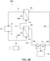
- FIG. 9A is a schematic configuration diagram showing Modification 1 of the membrane separation system 1000 of the present embodiment.
- a membrane separation system 1001 of Modification 1 includes two membrane separation devices 100A and 100B connected to each other in series.
- the membrane separation devices 100A and 100B are connected to each other with pipes.
- the membrane separation system 1001 has the same configuration as that of the membrane separation system 1000, except that the membrane separation system 1001 includes the two membrane separation devices 100A and 100B, and so on. Therefore, the elements common between the above-mentioned membrane separation system 1000 and the membrane separation system 1001 of Modification 1 are denoted by the same reference numerals, and the description of such elements may be omitted. That is, the description of one embodiment is applicable to the other embodiment unless technical inconsistency occurs. Furthermore, the features of the embodiments may be combined with each other unless technical inconsistency occurs.
- the membrane separation devices 100A and 100B are connected to each other in series in the membrane separation system 1001.
- the membrane separation system 1001 further includes a connection passage 74 that connects the membrane separation devices 100A and 100B to each other.
- the connection passage 74 is connected to the feed space outlet 13b of the membrane separation device 100A and the feed space inlet 13a of the membrane separation device 100B.
- the fermented liquid feed passage 71 is connected to the feed space inlet 13a of the membrane separation device 100A
- the non-permeated fluid discharge passage 73 is connected to the feed space outlet 13b of the membrane separation device 100B.
- the permeated fluid discharge passage 72 has a first portion 72A and a second portion 72B.
- the first portion 72A is connected to the permeation space outlet 14b of the membrane separation device 100A
- the second portion 72B is connected to the permeation space outlet 14b of the membrane separation device 100B.
- the first portion 72A joins the second portion 72B at a joining point 75.
- the permeated fluid discharge passage 72 is provided with two decompression devices 40A and 40B, for example.
- the decompression device 40A is positioned between the membrane separation device 100A and the joining point 70, and can decompress the inside of the permeation space 14 of the membrane separation device 100A.
- the decompression device 40B is positioned between the membrane separation device 100B and the joining point 70, and can decompress the inside of the permeation space 14 of the membrane separation device 100B.
- the permeated fluid discharge passage 72 may be provided with one decompression device, and the decompression device may be positioned between the joining point 70 and the recovery unit 50. That is, one decompression device may be shared by the membrane separation devices 100A and 100B.
- a pervaporation membrane 11A of the membrane separation device 100A may be the same as or different from a pervaporation membrane 11B of the membrane separation device 100B except for its membrane area.
- a ratio of a membrane area (m 2 ) of the pervaporation membrane 11A with respect to a total value (m 2 ) of the membrane area of the pervaporation membrane 11A and a membrane area of the pervaporation membrane 11B is not particularly limited.
- the membrane separation system 1001 can be operated by the following method. First, a pump (not shown) is activated and the fermented liquid S is supplied from the tank 30 to the membrane separation device 100A , and the fermented liquid S is further supplied to the membrane separation device 100B from the membrane separation device 100A. Thereby, each of the pervaporation membrane 11A of the membrane separation device 100A and the pervaporation membrane 11B of the membrane separation device 100B can be brought into contact with the fermented liquid S.
- the permeation space 14 of the membrane separation device 100A is decompressed via the permeation space outlet 14b, and the permeation space 14 of the membrane separation device 100B is decompressed via the permeation space outlet 14b.
- the operation of membrane separation can be executed by each of the membrane separation devices 100A and 100B, and the permeated fluid S1 can be obtained from each of the membrane separation devices 100A and 100B.
- the fermented liquid S (the non-permeated fluid S2) processed by the membrane separation device 100A is delivered to the membrane separation device 100B via the connection passage 74 and further processed by the membrane separation device 100B.
- both of the plurality of the membrane separation devices 100 may be arranged in the horizontal direction and connected to each other in series as shown in FIG. 9A .
- Such a configuration makes it possible to sufficiently secure stability of each of the membrane separation devices 100.
- the plurality of the membrane separation devices 100 may be arranged one above the other in the vertical direction and connected to each other in series as shown in FIG. 9B .
- Such a configuration makes it possible to reduce the number of the pipes to be used for connection.
- FIG. 10 is a schematic configuration diagram showing Modification 2 of the membrane separation system 1000 of the present embodiment.
- a membrane separation system 1002 of Modification 2 includes the two membrane separation devices 100A and 100B connected to each other in parallel.
- the membrane separation devices 100A and 100B are connected to each other with pipes.
- the membrane separation system 1002 has the same configuration as that of the membrane separation system 100, except that the membrane separation system 1002 includes the two membrane separation devices 100A and 100B, and so on.
- the membrane separation devices 100A and 100B are connected to each other in parallel.
- the fermented liquid feed passage 71 has a first portion 71A and a second portion 71B.
- the first portion 71A of the fermented liquid feed passage 71 is connected to the feed space inlet 13a of the membrane separation device 100A
- the second portion 71B is connected to the feed space inlet 13a of the membrane separation device 100B.
- the second portion 71B is branched from the first portion 71A at a branch point 76.
- the branch point 76 is positioned between the tank 30 and the membrane separation device 100A.
- the non-permeated fluid discharge passage 73 has a first portion 73A and a second portion 73B.
- the first portion 73A of the non-permeated fluid discharge passage 73 is connected to the feed space outlet 13b of the membrane separation device 100A, and the second portion 73B is connected to the feed space outlet 13b of the membrane separation device 100B.
- the first portion 73A joins the second portion 73B at a joining point 77.
- the joining point 77 is positioned between the tank 30 and the membrane separation device 100A, for example.
- the permeated fluid discharge passage 72 has the first portion 72A and the second portion 72B.
- the first portion 72A is connected to the permeation space outlet 14b of the membrane separation device 100A
- the second portion 72B is connected to the permeation space outlet 14b of the membrane separation device 100B.
- the first portion 72A joins the second portion 72B at the joining point 75.
- the permeated fluid discharge passage 72 is provided with the two decompression devices 40A and 40B, for example.
- the decompression device 40A is positioned between the membrane separation device 100A and the joining point 75, and can decompress the inside of the permeation space 14 of the membrane separation device 100A.
- the decompression device 40B is positioned between the membrane separation device 100B and the joining point 75, and can decompress the inside of the permeation space 14 of the membrane separation device 100B.
- the permeated fluid discharge passage 72 may be provided with one decompression device, and the decompression device may be positioned between the joining point 75 and the recovery unit 50. That is, one decompression device may be shared by the membrane separation devices 100A and 100B.
- the pervaporation membrane 11A of the membrane separation device 100A may be the same as or different from the pervaporation membrane 11B of the membrane separation device 100B.
- the ratio of the membrane area (m 2 ) of the pervaporation membrane 11A with respect to the total value (m 2 ) of the membrane area of the pervaporation membrane 11A and the membrane area of the pervaporation membrane 11B is not particularly limited.
- the membrane separation system 1002 can be operated by the following method. First, a pump (not shown) is activated and the fermented liquid S is supplied from the tank 30 to each of the membrane separation devices 100A and 100B. Thereby, each of the pervaporation membrane 11A of the membrane separation device 100A and the pervaporation membrane 11B of the membrane separation device 100B can be brought into contact with the fermented liquid S.
- the permeation space 14 of the membrane separation device 100A is decompressed via the permeation space outlet 14b, and the permeation space 14 of the membrane separation device 100B is decompressed via the permeation space outlet 14b.
- the operation of membrane separation can be executed by each of the membrane separation devices100A and 100B, and the permeated fluid S1 can be obtained from each of the membrane separation devices 100A and 100B.
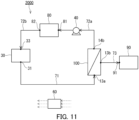
- FIG. 11 is a schematic configuration diagram showing an example of a membrane separation system 2000 of Embodiment 2.
- the membrane separation system 2000 of the present embodiment includes the above-mentioned membrane separation device 100, 101, 111, 121, 102 or 103 as the membrane separation device.
- the membrane separation device 100, 101, 111, 121, 102 or 103 is collectively referred to as the membrane separation device 100 for convenience.
- the elements common between the above-mentioned membrane separation system 1000 of Embodiment 2 and the membrane separation system 2000 of Embodiment 2 are denoted by the same reference numerals, and the description of such elements may be omitted.
- the pervaporation membrane 11 is a membrane (a dehydration membrane) that allows water contained in the fermented liquid S to preferentially permeate therethrough.
- the membrane separation system 2000 may further include a recovery unit 80 for recovering the permeated fluid S1.
- the recovery unit 80 recovers the permeated fluid S1 delivered from the membrane separation device 100 and can, for example, store the permeated fluid S1.
- the recovery unit 80 is, for example, a tank that stores the permeated fluid S1.
- the membrane separation system 2000 further includes the fermented liquid feed passage 71, a first permeated fluid discharge passage 72a, and the non-permeated fluid discharge passage 73.
- the fermented liquid feed passage 71 is a passage connected to the fermented liquid outlet (the outlet 31) of the tank 30 and the fermented liquid inlet (the inlet 13a) of the membrane separation device 100 and configured to supply the fermented liquid S from the tank 30 to the membrane separation device 100.
- the fermented liquid feed passage 71 may be provided with a pump that controls the flow rate of the fermented liquid S, and may be provided with a sensor for measuring the content of the organic compound in the fermented liquid S.
- the fermented liquid feed passage 71 may be provided with a filter for removing the microorganism that is contained in the fermented liquid S and that is associated with the generation of the fermented product.
- the first permeated fluid discharge passage 72a is a passage connected to the permeated fluid outlet (the outlet 14b) of the membrane separation device 100 and a permeated fluid inlet (an inlet 81) of the recovery unit 80 and configured to deliver the permeated fluid S1 from the membrane separation device 100 to the recovery unit 80.
- the first permeated fluid discharge passage 72a may be provided with the decompression device 40, and a sensor for measuring the content of the organic compound in the permeated fluid S1.
- the first permeated fluid discharge passage 72a may be further provided with a condensation unit for condensing the permeated fluid S1.
- the condensation unit is, for example, a heat exchanger for cooling the permeated fluid S1.
- the heat exchanger makes it possible to cool and condense the permeated fluid S1 that is a gas.
- the heat exchanger is, for example, a gas-liquid heat exchanger that causes heat exchange between a cooling medium, such as an antifreeze, and the permeated fluid S1 that is a gas.
- the condensation unit may be positioned between the membrane separation device 100 and the decompression device 40 (upstream of the decompression device 40), or between the decompression device 40 and the recovery unit 80 (downstream of the decompression device 40).
- the membrane separation system 2000 may further include a second permeated fluid discharge passage 72b.
- the second permeated fluid discharge passage 72b may be connected to a permeated fluid outlet (an outlet 82) of the recovery unit 80 and a permeated fluid inlet (an inlet 33) of the tank 30 and configured to deliver the permeated fluid S1 to the tank 30. That is, the membrane separation system 2000 may be configured to allow the permeated fluid S1 to be mixed with the fermented liquid S in the tank 30 and circulate through the fermented liquid feed passage 71, the first permeated fluid discharge passage 72a, and the second permeated fluid discharge passage 72b.
- the fermented liquid S is mixed with the permeated fluid S1 and the content of the organic compound in the fermented liquid S decreases in the tank 30.
- the tank 30 is a fermenter
- a decrease in the content of the organic compound in the fermented liquid S can inhibit the fermentation by a microorganism from stopping, thereby making it possible to produce the fermented product continuously.
- the non-permeated fluid discharge passage 73 is a passage connected to the non-permeated fluid outlet (the outlet 13b) of the membrane separation device 100 and configured to discharge the non-permeated fluid S2 from the membrane separation device 100.
- the non-permeated fluid discharge passage 73 may be provided with a sensor for measuring the content of the organic compound in the non-permeated fluid S2.
- the membrane separation system 2000 may further include a recovery unit 90 for recovering the non-permeated fluid S2.
- the non-permeated fluid discharge passage 73 may be connected to a non-permeated fluid inlet (an inlet 91) of the recovery unit 90.
- the recovery unit 90 recovers the non-permeated fluid S2 delivered from the membrane separation device 100 and can, for example, store the non-permeated fluid S2.
- the recovery unit 90 is, for example, a tank that stores the non-permeated fluid S2.
- the non-permeated fluid discharge passage 73 may be provided with a filter for removing the microorganism that is contained in the non-permeated fluid S2 and that is associated with the generation of the fermented product.
- the pervaporation membrane 11 preferably includes at least one selected from the group consisting of polyimide and zeolite.
- the pervaporation membrane 11 including at least one selected from the group consisting of polyimide and zeolite is suitable for removing water contained in the fermented liquid S, that is, suitably used for dehydration.
- the membrane separation system 2000 of the present embodiment may include a plurality of the membrane separation devices 100, and the plurality of the membrane separation devices 100 may be connected to each other in series or in parallel.
- Example 1 As the membrane separation device of Example 1, a spiral membrane separation device having the same configuration as that of the membrane separation device 101 shown in FIG. 4A was used. In the membrane separation device of Example 1, the tilt angle ⁇ 1 was set to 78°. The tilt angle ⁇ 3 was set to 90°.
- Example 2 As the membrane separation device of Example 2, a spiral membrane separation device having the same configuration as that of the membrane separation device 111 shown in FIG. 4B was used. In the membrane separation device of Example 2, the tilt angle ⁇ 1 was set to 32°. The tilt angle ⁇ 3 was set to 20°.
- Example 3 As the membrane separation device of Example 3, a spiral membrane separation device having the same configuration as that of the membrane separation device 111 shown in FIG. 4B was used. In the membrane separation device of Example 3, the tilt angle ⁇ 1 was set to 27°. The tilt angle ⁇ 3 was set to 15°.
- Example 4 As the membrane separation device of Example 4, a spiral membrane separation device having the same configuration as that of the membrane separation device 111 shown in FIG. 4B was used. In the membrane separation device of Example 4, the tilt angle ⁇ 1 was set to 22°. The tilt angle ⁇ 3 was set to 10°.
- Example 5 As the membrane separation device of Example 5, a spiral membrane separation device having the same configuration as that of the membrane separation device 111 shown in FIG. 4B was used. In the membrane separation device of Example 5, the tilt angle ⁇ 1 was set to 17°. The tilt angle ⁇ 3 was set to 5°.
- Example 6 As the membrane separation device of Example 6, a spiral membrane separation device having the same configuration as that of the membrane separation device 121 shown in FIG. 4C was used. In the membrane separation device of Example 6, the tilt angle ⁇ 1 was set to 12°. The tilt angle ⁇ 3 was set to 0°.
- a membrane separation device 300 shown in FIG. 12 was used as the membrane separation device of Comparative Example 1.
- the membrane separation device 300 had the same configuration as that of the membrane separation device 121 shown in FIG. 4C , except that the feed space inlet 13a was positioned above the feed space outlet 13b.
- the elements common between the membrane separation device 300 and the membrane separation device 101 shown in FIG. 4A are denoted by the same reference numerals for convenience.
- the tilt angle ⁇ 1 was set to 12°.
- the tilt angle ⁇ 3 was set to 0°.
- a pervaporation membrane was produced by the following method.
- a coating liquid was prepared by mixing 1.650 kg (solids concentration: 30 wt%) of a silicone resin (YSR3022 available from Momentive Performance Materials Japan LLC.), 2.805 kg of toluene, 0.495 kg of a high-silica zeolite (HiSiv 3000 available from UNION SHOWA K.K.), 0.0495 kg of a silicone curing catalyst (YC6831 available from Momentive Performance Materials Japan LLC.), and 0.0495 kg of acetylacetone as a curing retardant.
- a silicone resin YSR3022 available from Momentive Performance Materials Japan LLC.
- HiSiv 3000 available from UNION SHOWA K.K.
- a silicone curing catalyst YC6831 available from Momentive Performance Materials Japan LLC.
- acetylacetone as a curing retardant.
- the coating liquid was applied onto a porous support (RS-50 available from Nitto Denko Corporation) having a thickness of 150 ⁇ m to obtain a coating (thickness: 500 ⁇ m).
- the coating was heated at 90°C for 4 minutes and then dried to produce a separation functional layer having a thickness of 50 ⁇ m.
- the weight ratio between the silicone resin and the high-silica zeolite was 50:50 in the separation functional layer. A pervaporation membrane was thus obtained.
- a spiral membrane element as shown in FIG. 5 was produced using the produced pervaporation membrane.
- the membrane element had an outer diameter of 55 mm and a length of 300 mm.
- the produced membrane element was disposed inside a casing to produce a membrane separation device.
- the casing had an inner diameter of 62 mm.
- the amount of a liquid discharged was evaluated by the following method. Water was used as the liquid to circulate through the membrane separation device. The circulation flow rate was set to 100 g/minute. The liquid was allowed to circulate through the membrane separation device under the above-mentioned conditions so that the membrane element was sufficiently charged with the liquid. Thereafter, the circulation was stopped and the liquid inside the membrane element was discharged. The weight of the liquid discharged was considered as the amount of the liquid discharged. Table 1 shows the results. [Table 1] Feed space inlet 13a is positioned below feed space outlet 13b.
- Example 6 Yes 12 0 422 Comparative Example 1 No 12 0 201
- the amount of the liquid discharged was larger when the membrane separation device of each of Examples 1 to 6 was used than when the membrane separation device of Comparative Example 1 was used. That is, a larger amount of the liquid was charged into the membrane element when the membrane separation device of each of Examples 1 to 6 was used than when the membrane separation device of Comparative Example 1 was used.
- This result reveals that an increase of the local dried solidified area inside the membrane separation device was suppressed by using the membrane separation device in which the feed space inlet 13a was positioned below the feed space outlet 13b. Therefore, it is inferred that it is possible to suppress the growth of an undesirable microorganism inside the membrane separation device by using the membrane separation device in which the feed space inlet 13a is positioned below the feed space outlet 13b.
- the membrane separation device of Example 1 had a larger amount of the liquid discharged than that of any of the membrane separation devices of Examples 2 to 6. This result reveals that it is possible to achieve an excellent effect in suppressing an increase of the local dried solidified area inside the membrane separation device by using a spiral membrane separation device having the same configuration as that of the membrane separation device 101 shown in FIG. 4A .
- the membrane separation device of Example 6 had a larger amount of the liquid discharged than that of the membrane separation device of Comparative Example 1, and was easier to connect and install than the membrane separation devices of Examples 1 to 5.
- the membrane separation system of the present embodiment is suitable for efficiently separating a volatile organic compound from a fermented liquid containing the organic compound.
Landscapes
- Chemical & Material Sciences (AREA)
- Engineering & Computer Science (AREA)
- Water Supply & Treatment (AREA)
- Chemical Kinetics & Catalysis (AREA)
- Organic Chemistry (AREA)
- General Engineering & Computer Science (AREA)
- Biochemistry (AREA)
- Bioinformatics & Cheminformatics (AREA)
- Life Sciences & Earth Sciences (AREA)
- General Health & Medical Sciences (AREA)
- Genetics & Genomics (AREA)
- Health & Medical Sciences (AREA)
- Wood Science & Technology (AREA)
- Zoology (AREA)
- Separation Using Semi-Permeable Membranes (AREA)
- Apparatus Associated With Microorganisms And Enzymes (AREA)
Abstract
Description
- The present invention relates to a membrane separation device, a membrane separation system, and a method for operating a membrane separation device.
- There have been developed methods for producing a volatile organic compound (a fermented product), such as an alcohol, by fermenting a carbon source, such as glucose, by using a microorganism. The fermentation of a carbon source is carried out in an aqueous solution, for example. In this method, the fermentation by a microorganism stops in some cases when the content of the fermented product in the aqueous solution increases. In order to continue the production of the fermented product by a microorganism, it is necessary to separate the fermented product from the aqueous solution.
- As an example of the method for separating a volatile organic compound from an aqueous solution containing the organic compound, a pervaporation method using a separation membrane can be mentioned. The pervaporation method is suitable for separating a volatile organic compound from an aqueous solution containing various substances. The pervaporation method also tends to be able to better suppress the amount of energy consumption and the amount of carbon dioxide emission than a distillation method. By combining a membrane separation device that performs the pervaporation method with a fermenter that produces a fermented product, it is possible to produce a fermented product continuously. For example,
Patent Literature 1 discloses a membrane separation system obtained by combining a membrane separation device with a fermenter. - Patent Literature 1:
JP 2010-161987 A - Conventionally, the above-mentioned pervaporation method is performed by introducing, in a horizontal direction, a fermented liquid containing a volatile organic compound to a feed space of a membrane separation device. Studies by the present inventors show that in such a conventional membrane separation device, a local dried solidified area is likely to be formed and the fermented liquid is likely to stagnate inside the membrane separation device due to a factor such as variation in the amount of an aqueous solution to be supplied to the membrane separation device. Such a defect helps an undesirable microorganism to grow inside the membrane separation device. The growth of an undesirable microorganism inside the membrane separation device causes a separation membrane to clog, lowering the separation performance of the separation membrane. This leads to a problem in the operation of the membrane separation system and makes it difficult to produce a fermented product stably.
- Therefore, the present invention is intended to provide a membrane separation device suitable for suppressing the growth of an undesirable microorganism inside the membrane separation device.
- The present invention provides a membrane separation device including:
- a pervaporation membrane that separates a fermented liquid containing a volatile organic compound into a permeated fluid and a non-permeated fluid;
- a feed space and a permeation space separated from each other by the pervaporation membrane;
- a feed space inlet for supplying the fermented liquid to the feed space; and
- a feed space outlet for discharging the non-permeated fluid from the feed space, wherein
- the feed space inlet is positioned below the feed space outlet.
- In another aspect, the present invention provides
a membrane separation system including the membrane separation device of the present invention. - In still another aspect, the present invention provides a method for operating a membrane separation device including:
- a pervaporation membrane that separates a fermented liquid containing a volatile organic compound into a permeated fluid and a non-permeated fluid;
- a feed space and a permeation space separated from each other by the pervaporation membrane;
- a feed space inlet for supplying the fermented liquid to the feed space; and
- a feed space outlet for discharging the non-permeated fluid from the feed space,
- the feed space inlet being positioned below the feed space outlet,
- the method including:
- supplying the fermented liquid to the membrane separation device from the feed space inlet; and
- separating the fermented liquid into the permeated fluid and the non-permeated fluid with the pervaporation membrane.
- The present invention can provide a membrane separation device suitable for suppressing the growth of an undesirable microorganism inside the membrane separation device.
-
-
FIG. 1 is a schematic cross-sectional view showing an example of a membrane separation device of the present embodiment. -
FIG. 2 is a diagram for explaining a tilt angle in the membrane separation device of the present embodiment. -
FIG. 3 is a schematic cross-sectional view of a pervaporation membrane included in the membrane separation device of the present embodiment. -
FIG. 4A is a schematic cross-sectionalview showing Modification 1 of the membrane separation device of the present embodiment. -
FIG. 4B is a schematic cross-sectional view showing another example ofModification 1 of the membrane separation device of the present embodiment. -
FIG. 4C is a schematic cross-sectional view showing still another example ofModification 1 of the membrane separation device of the present embodiment. -
FIG. 5 is a developed perspective view showing schematically a spiral membrane element. -
FIG. 6 is a schematic cross-sectionalview showing Modification 2 of the membrane separation device of the present embodiment. -
FIG. 7 is a schematic cross-sectional view showing Modification 3 of the membrane separation device of the present embodiment. -
FIG. 8 is a schematic configuration diagram showing an example of a membrane separation system ofEmbodiment 1. -
FIG. 9A is a schematic configurationdiagram showing Modification 1 of the membrane separation system ofEmbodiment 1. -
FIG. 9B is a schematic configuration diagram showing another example ofModification 1 of the membrane separation system ofEmbodiment 1. -
FIG. 10 is a schematic configurationdiagram showing Modification 2 of the membrane separation system ofEmbodiment 1. -
FIG. 11 is a schematic configuration diagram showing an example of a membrane separation system ofEmbodiment 2. -
FIG. 12 is a schematic configuration diagram showing a membrane separation device of Comparative Example 1. - A membrane separation device according to a first aspect of the present invention includes:
- a pervaporation membrane that separates a fermented liquid containing a volatile organic compound into a permeated fluid and a non-permeated fluid;
- a feed space and a permeation space separated from each other by the pervaporation membrane;
- a feed space inlet for supplying the fermented liquid to the feed space; and
- a feed space outlet for discharging the non-permeated fluid from the feed space, wherein
- the feed space inlet is positioned below the feed space outlet.
- According to a second aspect of the present invention, for example, the membrane separation device according to the first aspect further includes:
- a central tube having a through hole; and
- a membrane leaf that has the pervaporation membrane and is wound around the central tube.
- According to a third aspect of the present invention, for example, in the membrane separation device according to the second aspect,
the central tube extends from a lower side to an upper side. - According to a fourth aspect of the present invention, for example, in the membrane separation device according to any one of the first to third aspects,
a tilt angle of a virtual straight line connecting the feed space inlet to the feed space outlet with respect to a level surface is 5° or more and 90° or less. - According to a fifth aspect of the present invention, for example, the membrane separation device according to any one of the first to fourth aspects further includes
- a permeation space outlet for discharging the permeated fluid from the permeation space, wherein
- the permeation space outlet is positioned above the feed space inlet.
- According to a sixth aspect of the present invention, for example, the membrane separation device according to any one of the first to fifth aspects further includes
- a fluid discharge outlet connected to the feed space, wherein
- the fluid discharge outlet is positioned below the feed space outlet.
- According to a seventh aspect of the present invention, for example, in the membrane separation device according to any one of the first to sixth aspects,
a content of the organic compound in the permeated fluid is higher than a content of the organic compound in the fermented liquid. - According to an eighth aspect of the present invention, for example, in the membrane separation device according to any one of the first to seventh aspects,
the fermented liquid is separated into the permeated fluid and the non-permeated fluid in a state in which the feed space is filled with the fermented liquid. - A membrane separation system according to a ninth aspect of the present invention includes
the membrane separation device according to any one of the first to eighth aspects. - According to a tenth aspect of the present invention, for example, the membrane separation system according to the ninth aspect further includes
a tank that stores the fermented liquid to be supplied to the membrane separation device. - According to an eleventh aspect of the present invention, for example, the membrane separation system according to the tenth aspect further includes:
- a fermented liquid feed passage connecting the tank to the feed space inlet; and
- a non-permeated fluid discharge passage connecting the feed space outlet to the tank.
- According to a twelfth aspect of the present invention, for example, in the membrane separation system according to the tenth or eleventh aspect,
the tank is a fermenter for generating the organic compound. - According to a thirteenth aspect of the present invention, for example, in the membrane separation system according to any one of the ninth to twelfth aspects,
- the membrane separation system includes a plurality of the membrane separation devices, and
- the plurality of the membrane separation devices are connected to each other in series or in parallel.
- A method for operating a membrane separation device according to a fourteenth aspect of the present invention is a method for operating a membrane separation device including:
- a pervaporation membrane that separates a fermented liquid containing a volatile organic compound into a permeated fluid and a non-permeated fluid;
- a feed space and a permeation space separated from each other by the pervaporation membrane;
- a feed space inlet for supplying the fermented liquid to the feed space; and
- a feed space outlet for discharging the non-permeated fluid from the feed space,
- the feed space inlet being positioned below the feed space outlet,
- the method including:
- supplying the fermented liquid to the membrane separation device from the feed space inlet; and
- separating the fermented liquid into the permeated fluid and the non-permeated fluid with the pervaporation membrane.
- The present invention will be described in detail below. The following description is not intended to limit the present invention to a specific embodiment.
-
FIG. 1 is a schematic cross-sectional view showing an example of amembrane separation device 100 of the present embodiment. As shown inFIG. 1 , themembrane separation device 100 includes: apervaporation membrane 11 that separates a fermented liquid S containing a volatile organic compound into a permeated fluid S1 and a non-permeated fluid S2; afeed space 13 and apermeation space 14 separated from each other by thepervaporation membrane 11; afeed space inlet 13a for supplying the fermented liquid S to thefeed space 13; and afeed space outlet 13b for discharging the non-permeated fluid S2 from thefeed space 13. Thefeed space inlet 13a is positioned below thefeed space outlet 13b. Themembrane separation device 100 is a device that performs membrane separation, during its operation, for the fermented liquid S containing a volatile organic compound by using thepervaporation membrane 11. - As described above, the
feed space inlet 13a is positioned below thefeed space outlet 13b in themembrane separation device 100. This makes it possible to introduce the fermented liquid S to themembrane separation device 100 in such a manner that the fermented liquid S flows from a lower side to an upper side inside themembrane separation device 100. Thereby, formation of a local dried solidified area and stagnation of the fermented liquid S inside themembrane separation device 100 due to a factor such as variation in the amount of the fermented liquid S to be supplied to themembrane separation device 100 tend to be avoided. Accordingly, the growth of an undesirable microorganism inside themembrane separation device 100 is suppressed. - The
membrane separation device 100 further includes acasing 12. Inside thecasing 12, thefeed space 13 and thepermeation space 14 are provided. Thefeed space 13 functions as a feed space to which the fermented liquid S is supplied. Thepermeation space 14 functions as a permeation space to which the permeated fluid S1 is supplied. The permeated fluid S1 is obtained by allowing the fermented liquid S to permeate through thepervaporation membrane 11. Thepervaporation membrane 11 is disposed inside thecasing 12. Inside thecasing 12, thepervaporation membrane 11 separates thefeed space 13 and thepermeation space 14 from each other. Thepervaporation membrane 11 extends from one of a pair of wall surfaces of thecasing 12 to the other. - The
membrane separation device 100 further includes apermeation space outlet 14b for discharging the permeated fluid S1 from thepermeation space 14. Thepermeation space outlet 14b may be positioned above thefeed space inlet 13a. Such a configuration makes it possible to recover easily the permeated fluid S1 that is a gas and that has been discharged from themembrane separation device 100. Thepermeation space outlet 14b may be positioned at the same height as that of thefeed space outlet 13b. - The
permeation space outlet 14b may be positioned at the same height as that of thefeed space inlet 13a, or may be positioned below thefeed space inlet 13a. Such a configuration makes it possible to recover easily the permeated fluid S1 even when the permeated fluid S1 discharged from themembrane separation device 100 is liquefied. Thepermeation space outlet 14b may be positioned below thefeed space outlet 13b. - The
feed space 13 communicates with thefeed space inlet 13a and thefeed space outlet 13b. Thepermeation space 14 communicates with thepermeation space outlet 14b. Thefeed space inlet 13a is an opening for supplying the fermented liquid S to themembrane separation device 100. Thepermeation space outlet 14b is an opening for discharging the permeated fluid S1 from themembrane separation device 100. Thefeed space outlet 13b is an opening for discharging, from themembrane separation device 100, the fermented liquid S (a non-permeated fluid S2) not having permeated through thepervaporation membrane 11. Thefeed space inlet 13a, thefeed space outlet 13b, and thepermeation space outlet 14b are formed, for example, in wall surfaces of thecasing 12. - The
feed space inlet 13a may be formed in a lower face of thecasing 12, and thefeed space outlet 13b and thepermeation space outlet 14b may be formed in an upper face of thecasing 12. Thefeed space inlet 13a may be formed in a side face of thecasing 12. Thefeed space outlet 13b may be formed in the side face of thecasing 12. Thepermeation space outlet 14b may be formed in the side face of thecasing 12. - A shape of the
casing 12 is not particularly limited as long as the fermented liquid S can be introduced in such a manner as to flow from the lower side to the upper side inside themembrane separation device 100. Thecasing 12 may have a prismatic shape or a cylindrical shape, for example. As shown inFIG. 1 , in the case where thecasing 12 has a longitudinal direction, thecasing 12 may be placed in such a manner that the longitudinal direction extends from the lower side to the upper side. Thecasing 12 may be placed vertically so that the longitudinal direction is along a vertical direction. -
FIG. 2 is a diagram for explaining a tilt angle in themembrane separation device 100 of the present embodiment. In themembrane separation device 100, a tilt angle of a virtual straight line L1 connecting thefeed space inlet 13a to thefeed space outlet 13b with respect to a level surface P is defined as θ1. Note that in the present embodiment, θ1 refers to a smallest angle between the virtual straight line L1 and the level surface P within a range from 0° or more to 90° or less. In the case where thefeed space inlet 13a and thefeed space outlet 13b each are a circular or rectangular opening, the virtual straight line L1 can be defined as a virtual straight line connecting a center point of thefeed space inlet 13a to a center point of thefeed space outlet 13b. θ1 is 5° or more and 90° or less, for example. According to such a structure, formation of a local dried solidified area and stagnation of the fermented liquid S inside themembrane separation device 100 are likely to be avoided. - θ1 may be 10° or more, 15° or more, 25° or more, 35° or more, 45° or more, 55° or more, or 65° or more. θ1 may be 75° or more and 90° or less. That is, θ1 may satisfy 75° ≤ θ1 ≤ 90°.
- Furthermore, θ1 may be 80° or more, or 85° or more. θ1 may be substantially 90°. In the present description, the term "substantially 90°" means to include a deviation of ±3° or less from 90°. The same applies to other angles.
- In the
membrane separation device 100, a tilt angle of a virtual straight line L2 connecting thefeed space inlet 13a to thepermeation space outlet 14b with respect to the level surface P is defined as θ2. Note that in the present embodiment, θ2 refers to a smallest angle between the virtual straight line L2 and the level surface P within a range from 0° or more to 90° or less. In the case where thefeed space inlet 13a and thepermeation space outlet 14b each are a circular or rectangular opening, the virtual straight line L2 can be defined as a virtual straight line connecting the center point of thefeed space inlet 13a to a center point of thepermeation space outlet 14b. - θ2 may be 5° or more, 15° or more, 25° or more, or 35° or more. θ2 may be 45° or more and 90° or less. That is, θ2 may satisfy 45° ≤ θ2 ≤ 90°.
- Furthermore, θ2 may be 50° or more, 55° or more, or 60° or more. The tilt angle θ2 may be substantially 75°.
- The
membrane separation device 100 may separate the fermented liquid S into the permeated fluid S1 and the non-permeated fluid S2 in a state in which thefeed space 13 is filled with the fermented liquid S. - The
membrane separation device 100 is suitable for a flow-type (continuous-type) membrane separation method. However, themembrane separation device 100 may be used for a batch-type membrane separation method. -
FIG. 3 is a schematic cross-sectional view of thepervaporation membrane 11 included in themembrane separation device 100. As shown inFIG. 3 , thepervaporation membrane 11 includes, for example, a separationfunctional layer 1 and aporous support member 2 supporting the separationfunctional layer 1. Thepervaporation membrane 11 may further include a protective layer (not shown) that protects the separationfunctional layer 1. The separationfunctional layer 1 is in direct contact with theporous support member 2, for example. For example, thepervaporation membrane 11 has aprincipal surface 11a, on the separation functional layer side, that is exposed to thefeed space 13 and aprincipal surface 11b, on the porous support member side, that is exposed to thepermeation space 14. - In a preferred embodiment of the present invention, the
pervaporation membrane 11 is a membrane (a concentration membrane) that allows the organic compound contained in the fermented liquid S to preferentially permeate therethrough. In the case where thepervaporation membrane 11 is a concentration membrane, a content of the organic compound in the permeated fluid S1 is higher than a content of the organic compound in the fermented liquid S. In contrast, a content of the organic compound in the non-permeated fluid S2 is lower than the content of the organic compound in the fermented liquid S. - In the case where the
pervaporation membrane 11 is a concentration membrane, the separationfunctional layer 1 is a layer that allows the organic compound contained in the fermented liquid S to preferentially permeate therethrough. The separationfunctional layer 1 includes a hydrophobic material, for example. In the present description, the term "hydrophobic material" refers to, for example, a material that has a static contact angle exceeding 90° with respect to water when a 10 µL drop of the water (temperature 25°C) is dropped on a surface of a specimen composed of the material. Note that the static contact angle with respect to water can be measured using a commercially available contact angle meter. - Examples of the hydrophobic material include a compound having a siloxane bond (a Si-O-Si bond), an olefin-based polymer, an oil, and a fluorine-based compound. The separation
functional layer 1 preferably includes a compound having a siloxane bond as the hydrophobic material. The compound having a siloxane bond is typically a silicone resin. The silicone resin may be a solid or a liquid at 25°C. Specific examples of the silicone resin include polydimethylsiloxane (PDMS). Specific examples of the olefin-based polymer include polyethylene and polypropylene. Examples of the oil include a hydrocarbon-based oil such as liquid paraffin. Examples of the fluorine-based compound include polytetrafluoroethylene (PTFE), polyvinylidene fluoride (PVDF), and tetrafluoroethylene-perfluoroalkyl vinyl ether copolymer (PFA). These hydrophobic materials can be used alone or two or more of them can be used in combination. - The separation
functional layer 1 may include a silicone resin. Thepervaporation membrane 11 that includes the separationfunctional layer 1 including a silicone resin is suitably used for concentrating the organic compound contained in the fermented liquid S. - The separation
functional layer 1 may include the hydrophobic material as a main component, or may be composed substantially of the hydrophobic material alone. The term "main component" means a component having a largest content in the separationfunctional layer 1 in terms of weight ratio. - The separation
functional layer 1 may include a matrix including the hydrophobic material and a filler dispersed in the matrix. The filler is buried in the matrix. In the matrix, all particles of the filler may be spaced from each other or may aggregate partially. - The filler includes, for example, an inorganic material such as zeolite, silica, or bentonite. The zeolite included in the filler is preferably a high-silica zeolite having a high ratio of silica with respect to alumina. Having high resistance to hydrolysis, the high-silica zeolite is suitably used for separating the aqueous solution S. Examples of the high-silica zeolite to be used include HSZ (registered trademark) available from Tosoh Corporation, HiSiv (registered trademark) available from UNION SHOWA K.K., USKY available from UNION SHOWA K.K., and Zeoal (registered trademark) available from Nakamura Choukou Co., Ltd.
- The filler may include a metal organic framework (MOF). The metal organic framework is also referred to as a porous coordination polymer (PCP). The metal organic framework is preferably hydrophobic. The metal organic framework includes a metal ion and an organic ligand, for example. Examples of the metal ion include a Zn ion. The organic ligand includes an aromatic ring, for example. Examples of the aromatic ring included in the organic ligand include an imidazole ring. Examples of the organic ligand include 2-methylimidazole. Specific examples of the metal organic framework include ZIF-8.
- The filler is in the form of particles, for example. The term "form of particles" herein includes spherical, elliptical, flaky, and fibrous forms. An average particle diameter of the filler is, for example, but not particularly limited to, 50 µm or less, preferably 20 µm or less, and more preferably 10 µm or less. The lower limit of the average particle diameter of the filler is 0.01 µm, for example. The average particle diameter of the filler can be determined by the following method, for example. First, a cross-section of the separation
functional layer 1 is observed using a transmission electron microscope. The area of a specific particle of the filler on the resulting electron microscope image is calculated by image processing. The diameter of a circle having the same area as the calculated area is regarded as the particle diameter (the diameter of the particle) of the specific filler particle. The particle diameter was calculated for any number (at least 50) of the filler particles, and the average of the calculated values was regarded as the average particle diameter of the filler. - A content of the filler in the separation
functional layer 1 that includes the matrix including the hydrophobic material is, for example, 10 wt% or more, preferably 30 wt% or more, and more preferably 40 wt% or more. The upper limit of the content of the filler in the separationfunctional layer 1 is, for example, but not particularly limited to, 70 wt%. A content of the matrix in the separationfunctional layer 1 is, for example, but not particularly limited to, 30 wt% to 90 wt%. - The separation
functional layer 1 has a thickness of, for example, 200 µm or less, preferably 100 µm or less, and more preferably 80 µm or less. The separationfunctional layer 1 may have a thickness of 1.0 µm or more, 10 µm or more, or 30 µm or more. - The separation
functional layer 1 may have a microporous structure with an average pore diameter of less than 0.01 µm, but may be a dense layer having no pore on its surface. - Examples of the
porous support member 2 include: a nonwoven fabric; porous polytetrafluoroethylene; aromatic polyamide fiber; a porous metal; a sintered metal; porous ceramic; porous polyester; porous nylon; activated carbon fiber; latex; silicone; silicone rubber; a permeable (porous) polymer including at least one selected from the group consisting of polyvinyl fluoride, polyvinylidene fluoride, polyurethane, polypropylene, polyethylene, polystyrene, polycarbonate, polysulfone, polyether ether ketone, polyacrylonitrile, polyimide, and polyphenylene oxide; a metallic foam having an open cell or a closed cell; a polymer foam having an open cell or a closed cell; silica; a porous glass; and a mesh screen. Theporous support member 2 may be a combination of two or more of these materials. - The
porous support member 2 has an average pore diameter of 0.01 to 0.4 µm, for example. A thickness of theporous support 2 is, for example, but not particularly limited to, 10 µm or more, preferably 50 µm or more, and more preferably 100 µm or more. The thickness of theporous support 2 is, for example, 300 µm or less, and preferably 200 µm or less. - The protective layer covers a surface of the separation
functional layer 1, for example. A material of the protective layer is, for example, but not particularly limited to, a silicone resin. The material of the protective layer may be the same as or different from that of the matrix of the separationfunctional layer 1. A thickness of the protective layer is, for example, but not particularly limited to, 0.5 µm or more, preferably 1 µm or more, more preferably 5 µm or more, and still more preferably 10 µm or more. The thickness of the protective layer is, for example, 100 µm or less, preferably 50 µm or less, and more preferably 30 µm or less. - The
pervaporation membrane 11 can be produced by, for example, forming the separationfunctional layer 1 on theporous support member 2. Specifically, a coating liquid containing the materials of the separationfunctional layer 1 is prepared first. The coating liquid may contain, in addition to the filler, a dispersant for dispersing the filler in the coating liquid. For example, in the case where the coating liquid contains the compound having a siloxane bond, the coating liquid may further contain a catalyst for curing the compound. Next, the coating liquid is applied onto theporous support 2 to obtain a coating. The coating is dried to obtain the separationfunctional layer 1. Thus, thepervaporation membrane 11 can be obtained. - In another preferred embodiment of the present invention, the
pervaporation membrane 11 is a membrane (a dehydration membrane) that allows water contained in the fermented liquid S to preferentially permeate therethrough. In the case where thepervaporation membrane 11 is a dehydration membrane, the content of the organic compound in the permeated fluid S1 is lower than the content of the organic compound in the fermented liquid S. In contrast, the content of the organic compound in the non-permeated fluid S2 is higher than the content of the organic compound in the fermented liquid S. - In the case where the
pervaporation membrane 11 is a dehydration membrane, the separationfunctional layer 1 is a layer that allows water contained in the fermented liquid S to preferentially permeate therethrough. The separationfunctional layer 1 may include at least one selected from the group consisting of polyimide and zeolite. Zeolite has high hydrophilicity. Polyimide is a material that can better suppress swelling with water than zeolite. Specific examples of the zeolite include crystalline silicate such as silicalite-1 or silicalite-2, and crystalline titanosilicate such as TS-1. Thepervaporation membrane 11 that includes the separationfunctional layer 1 including at least one selected from the group consisting of polyimide and zeolite is suitable for removing water contained in the fermented liquid S, that is, suitably used for dehydration. - The separation
functional layer 1 may include polyimide as a main component, or may be composed substantially of polyimide alone. The separationfunctional layer 1 may include zeolite as a main component, or may be composed substantially of zeolite alone. - The separation
functional layer 1 may include a matrix including at least one selected from the group consisting of polyimide and zeolite, and a filler dispersed in the matrix. The filler is buried in the matrix. In the matrix, all particles of the filler may be spaced from each other or may aggregate partially. As the filler, the one mentioned as usable for the separationfunctional layer 1 in the case where thepervaporation membrane 11 is a concentration membrane can be used. - A content of the filler in the separation
functional layer 1 that includes the matrix including at least one selected from the group consisting of polyimide and zeolite is, for example, 10 wt% or more, preferably 30 wt% or more, and more preferably 40 wt% or more. The upper limit of the content of the filler in the separationfunctional layer 1 is, for example, but not particularly limited to, 70 wt%. A content of the matrix in the separationfunctional layer 1 is, for example, but not particularly limited to, 30 wt% to 90 wt%. - The separation
functional layer 1 has a thickness of, for example, 200 µm or less, preferably 100 µm or less, and more preferably 80 µm or less. The separationfunctional layer 1 may have a thickness of 1.0 µm or more, 10 µm or more, and 30 µm or more. - The separation
functional layer 1 may have a microporous structure with an average pore diameter of less than 0.01 µm, but may be a dense layer having no pore on its surface. - As the
porous support member 2, the one mentioned as theporous support member 2 in the case where thepervaporation membrane 11 is a concentration membrane can be used. - As the protective layer, the one mentioned as the protective layer in the case where the
pervaporation membrane 11 is a concentration membrane can be used. - The
pervaporation membrane 11 can be produced by the same method as that used in the case where thepervaporation membrane 11 is a concentration membrane. - A method for operating the
membrane separation device 100 includes: supplying the fermented liquid S to themembrane separation device 100 from thefeed space inlet 13a; and separating the fermented liquid S into the permeated fluid S1 and the non-permeated fluid S2 with thepervaporation membrane 11. According to the method for operating themembrane separation device 100, formation of a local dried solidified area and stagnation of the fermented liquid S inside themembrane separation device 100 due to a factor such as variation in the amount of the fermented liquid S to be supplied to themembrane separation device 100 are avoided. Accordingly, the growth of an undesirable microorganism inside themembrane separation device 100 is suppressed. - Specifically, the method for operating the
membrane separation device 100 is carried out as follows, for example. First, the fermented liquid S is supplied to thefeed space 13 of themembrane separation device 100 from the lower side to the upper side via thefeed space inlet 13a positioned below thefeed space outlet 13b. This makes it possible to bring the fermented liquid S into contact with one surface (theprincipal surface 11a, for example) of thepervaporation membrane 11. - The fermented liquid S contains, for example, the organic compound as a fermented product, and water. The organic compound contained in the fermented liquid S is not particularly limited as long as the organic compound has volatility. In the present description, the term "organic compound having volatility" refers to an organic compound that has a boiling point of 20 to 260°C, preferably 50°C to 260°C, under an atmospheric pressure (101.325 kPa). Note that the organic compound allows, for example, an aqueous phase containing water as a main component and an organic phase having a content of the organic compound higher than that in the aqueous phase to be generated when a concentration of the organic compound is high in the aqueous solution.
- The number of carbon atoms in the organic compound is, for example, but not particularly limited to, 10 or less, and may be 8 or less, 6 or less, or even 4 or less. The lower limit of the number of carbon atoms in the organic compound may be 1 or 2. The organic compound has, for example, a functional group including an oxygen atom, such as a hydroxyl group, a carbonyl group, an ether group, and an ester group. In the organic compound, the number of the functional groups including an oxygen atom is typically one.
- Examples of the organic compound include an alcohol, ketone, and ester. In the case where the organic compound is an alcohol, the organic compound is likely to be compatible with water and thus unlikely to cause unevenness in an environment in its system. The alcohol may be an alkyl alcohol composed only of an alkyl group and a hydroxyl group, or may be an aryl alcohol including an aryl group and a hydroxyl group. The alkyl alcohol may be linear, branched, or cyclic. Examples of the alkyl alcohol as the organic compound include methanol, ethanol, n-propanol, isopropanol, n-butanol (BuOH), 2-butanol, isobutanol, t-butanol, and n-pentanol, and preferred is n-butanol. N-butanol is a compound that allows two phases (an aqueous phase and an organic phase) to be generated from an aqueous solution thereof when a content of the compound in the aqueous solution is around 8 wt% or more. Therefore, in the case where the organic compound is n-butanol, it is possible, by adjusting the content of the organic compound in the permeated fluid to be around 8 wt% or more, for example, to generate an aqueous phase and an organic phase in the permeated fluid after the permeated fluid is liquefied. In this case, it is possible to refine the permeated fluid easily by separating the aqueous phase and the organic phase from each other. Examples of the aryl alcohol include phenol.
- The ketone may be dialkylketone composed only of an alkyl group and a carbonyl group. Examples of the dialkylketone as the organic compound include methyl ethyl ketone (MEK) and acetone.
- The ester may be aliphatic alkylester composed only of an alkyl group and an ester group. Examples of the aliphatic alkylester include ethyl acetate.
- Note that the organic compound is not limited to those mentioned above. The organic compound may be aromatic hydrocarbon such as benzene, toluene, or xylene.
- The fermented liquid S may contain one kind of the organic compound, or two or more kinds of the organic compounds. The content of the organic compound in the fermented liquid S is, for example, 50 wt% or less, and may be 30 wt% or less, 10 wt% or less, 5 wt% or less, 2 wt% or less, or even 1 wt% or less. The lower limit of the content of the organic compound is, for example, but not particularly limited to, 0.01 wt%.
- In the present embodiment, the organic compound is a fermented product generated by fermentation of a carbon source by a microorganism. That is, in the present embodiment, the fermented liquid S is a fermented liquid containing the organic compound as the fermented product.
- The fermented liquid S may further contain, other than water and the organic compound, an additional component, such as a microorganism associated with the generation of the fermented product, a carbon source, a nitrogen source, or an inorganic ion. The microorganism associated with the generation of the fermented product is typically a bacterium. Examples of the carbon source include polysaccharides such as starch, and monosaccharides such as glucose.
- The amount of the fermented liquid S to be supplied to the
membrane separation device 100 is not particularly limited and is determined according to the processing capacity of themembrane separation device 100. The fermented liquid S to be supplied to thefeed space 13 may be heated in advance. In one example, the fermented liquid S to be supplied to thefeed space 13 has a temperature of 15°C to 75°C. - Next, in a state in which the fermented liquid S is in contact with one surface of the
pervaporation membrane 11, a space adjacent to another surface (theprincipal surface 11b, for example) of thepervaporation membrane 11 is decompressed. Specifically, an inside of thepermeation space 14 is decompressed via thepermeation space outlet 14b. The inside of thepermeation space 14 can be decompressed by, for example, a decompression device such as a vacuum pump. A pressure in thepermeation space 14 is, for example, 50 kPa or less, and may be 20 kPa or less, 10 kPa or less, 5 kPa or less, 3 kPa or less, or even 2 kPa or less. In the present description, the term "pressure" means an absolute pressure unless otherwise noted. - For example, in the case where the
pervaporation membrane 11 is a concentration membrane, decompressing the inside of thepermeation space 14 makes it possible to obtain, on the side of the other surface of thepervaporation membrane 11, the permeated fluid S1 having a high content of the organic compound. In other words, the permeated fluid S1 is supplied to thepermeation space 14. The permeated fluid S1 is discharged outside themembrane separation device 100 via thepermeation space outlet 14b. The permeated fluid S1 that is a gas is cooled in a condensation unit, etc., for example. Thereby, the permeated fluid S1 is liquefied to obtain the permeated fluid S1 that is a liquid. - Meanwhile, in the case where the
pervaporation membrane 11 is a concentration membrane, the content of the organic compound in the fermented liquid S gradually decreases from thefeed space inlet 13a toward thefeed space outlet 13b in thefeed space 13. The fermented liquid S (the non-permeated fluid S2) processed in thefeed space 13 is discharged outside the firstmembrane separation device 100 via thefeed space outlet 13b. The non-permeated fluid S2 is typically a liquid. - As described above, in the case where the
pervaporation membrane 11 is a concentration membrane, thepervaporation membrane 11 of themembrane separation device 100 allows the organic compound contained in the fermented liquid S to preferentially permeate therethrough. Accordingly, the permeated fluid S1 obtained by the operation of themembrane separation device 100 has a content of the organic compound higher than that in the fermented liquid S to be supplied to themembrane separation device 100. - A washing operation for the
membrane separation device 100 may be executed after the operation of membrane separation is executed for a certain period of time according to the above method for operating themembrane separation device 100. The washing operation for themembrane separation device 100 may be executed regularly. - The operating method of the present embodiment makes it possible, for example, to produce the permeated fluid S1 having a high content of the organic compound. In other words, the operating method of the present embodiment makes it possible to produce the organic compound as the permeated fluid S1.
- In another aspect, the present invention provides a method for producing an organic compound, including:
- supplying the fermented liquid S containing the volatile organic compound to the
membrane separation device 100 having thepervaporation membrane 11; - separating the fermented liquid S into the permeated fluid S1 and the non-permeated fluid S2 with the
pervaporation membrane 11; and - recovering the permeated fluid S1, wherein
- the content of the organic compound in the permeated fluid S1 is higher than the content of the organic compound in the fermented liquid S,
- the
membrane separation device 100 includes:- the
feed space 13 and thepermeation space 14 separated from each other by thepervaporation membrane 11; - the
feed space inlet 13a for supplying the fermented liquid S to thefeed space 13; and - the
feed space outlet 13b for discharging the non-permeated fluid S2 from thefeed space 13, and - the
feed space inlet 13a is positioned below thefeed space outlet 13b.
- the
-
FIG. 4A is a schematic cross-sectionalview showing Modification 1 of themembrane separation device 100 of the present embodiment. Amembrane separation device 101 ofModification 1 includes amembrane element 15 having thepervaporation membrane 11. Themembrane element 15 is disposed inside thecasing 12. Thefeed space inlet 13a is positioned below thefeed space outlet 13b. - The
membrane element 15 may be a spiral membrane element, a hollow fiber membrane element, a disk tube membrane element in which a plurality of pervaporation membranes are laminated, a plate-and-flame membrane element, or the like. Themembrane element 15 is typically a spiral membrane element.FIG. 4A shows an example in the case where themembrane element 15 is a spiral membrane element. -
FIG. 5 is a developed perspective view showing schematically a spiral membrane element. Themembrane element 15 may be a spiral membrane element as shown inFIG. 5 . Thespiral membrane element 15 inFIG. 5 has acentral tube 16 and thepervaporation membrane 11, and includes amembrane leaf 17 that is wound around thecentral tube 16. Thecentral tube 16 extends from the lower side to the upper side. Thecentral tube 16 may extend in the vertical direction. - The
central tube 16 has a cylindrical shape. Thecentral tube 16 has a surface with a throughhole 16h formed therein to allow the permeated fluid S1 to flow into thecentral tube 16. The number of the throughholes 16h is not particularly limited and may be one, or two or more. Examples of a material of thecentral tube 16 include: a resin such as an acrylonitrile-butadiene-styrene copolymer resin (an ABS resin), a polyphenylene ether resin (a PPE resin), or a polysulfone resin (a PSF resin); and a metal such as stainless steel or titanium. Thecentral tube 16 has an inner diameter in a range of, for example, 20 to 100 mm. - The
membrane element 15 has a plurality of the membrane leaves 17. Each of the membrane leaves 17 further includes thepervaporation membrane 11 and a permeation-sideflow passage material 19. For example, each of the membrane leaves 17 has two pieces of thepervaporation membranes 11. The two pieces of thepervaporation membranes 11 are stacked with each other and sealed on three sides in such a manner as to have a bag-like structure. The permeation-sideflow passage material 19 is disposed between the two pieces of thepervaporation membranes 11 in such a manner as to be positioned inside the bag-like structure. The permeation-sideflow passage material 19 secures, between the two pieces of thepervaporation membranes 11, a space (a permeation space) serving as a flow passage for the permeated fluid S1. As just described above, the permeation-sideflow passage material 19 is combined with thepervaporation membrane 11 and used. The number of the membrane leaves 17 is, for example, but not particularly limited to, 2 to 30. - The
membrane element 15 further has a feed-sideflow passage material 18. The feed-sideflow passage material 18 is positioned outside the above-mentioned bag-like structure and is laminated on themembrane leaf 17. Specifically, a plurality of the feed-sideflow passage materials 18 and a plurality of the membrane leaves 17 are laminated alternately. The feed-sideflow passage material 18 secures, between themembrane leaf 17 and themembrane leaf 17, a space (a feed space) serving as a flow passage for the fermented liquid S. - As the feed-side
flow passage material 18 and the permeation-sideflow passage material 19, a resin net, woven fabric, or knitted fabric composed of polyethylene, polypropylene, polyethylene terephthalate (PET), polyphenylene sulfide (PPS), or an ethylene-chlorotrifluoroethylene copolymer (ECTFE) can be used, for example. - As shown in
FIG. 4A , thecasing 12 has a casingmain body 12a, afirst end plate 12b, and asecond end plate 12c. The casingmain body 12a has a cylindrical shape and is made from a material having sufficient pressure resistance. Thefirst end plate 12b is attached to a lower-side end portion 23a of thecasing 12. Theend portion 23a of thecasing 12 is closed with thefirst end plate 12b. Thesecond end plate 12c is attached to an upper-side end portion 23b of thecasing 12. Theend portion 23b of thecasing 12 is closed with thesecond end plate 12c. - The
casing 12 has aport 21a, aport 21b, and aport 22b. These ports are ports for allowing an inside of thecasing 12 to communicate with an outside of thecasing 12. Theport 21a is provided at the lower-side end portion 23a of thecasing 12. Theport 21b and theport 22b are provided at the upper-side end portion 23b of thecasing 12. - The
port 21a may be provided to thefirst end plate 12b, and theport 22b may be provided to thesecond end plate 12c. Theport 21b and theport 22b may be provided to thesecond end plate 12c. - The
feed space inlet 13a communicates with theport 21a, and theport 21a is used as an inlet for the fermented liquid S. Thecentral tube 16 is connected to theport 22b at thepermeation space outlet 14b. That is, theport 22b is used as an outlet for the permeated fluid S1. Thefeed space outlet 13b communicates with theport 21b, and theport 21b is used as an outlet for the non-permeated fluid S2. Each of the ports may be a simple opening, or a nozzle-like opening as shown inFIG. 4 . - The
membrane separation device 101 further includes a sealingmember 24 disposed in a space between themembrane element 15 and thecasing 12. For example, the sealingmember 24 has a ring shape and surrounds themembrane element 15 in a circumferential direction. The sealingmember 24 is disposed on a lower end side of themembrane element 15. The sealingmember 24 divides an inner space of thecasing 12 into aspace 25a and aspace 25b. Thespace 25a is positioned below thespace 25b. - In the case where the
membrane element 15 is a spiral membrane element as shown inFIG. 5 , a tilt angle of a center axis L3 of themembrane element 15 with respect to the level surface P is defined as θ3. Note that in the present embodiment, θ3 refers to a smallest angle between the center axis L3 and the level surface P within a range from 0° or more to 90° or less. As shown inFIG. 4A , the center axis L3 can be defined as a center axis of thecentral tube 16. - θ3 may be 5° or more, 15° or more, 25° or more, or 35° or more. θ3 may be 45° or more and 90° or less. That is, θ3 may satisfy 45° ≤ θ3 ≤ 90°. According to such a structure, formation of a local dried solidified area and stagnation of the fermented liquid S inside the
membrane separation device 100 are likely to be avoided. - Furthermore, θ3 may be 50° or more, 55° or more, 60° or more, 65° or more, or 70° or more.
- In the
membrane separation device 101 shown inFIG. 4A , θ1 is 35° or more and 90° or less. As shown inFIG. 4A , θ1 may satisfy 35° ≤ θ1 ≤ 90°. - In the
membrane separation device 101 shown inFIG. 4A , θ2 is 55° or more and 90° or less. As shown inFIG. 4A , θ2 may satisfy 55° ≤ θ2 ≤ 90°. - In the
membrane separation device 101 shown inFIG. 4A , θ3 is substantially 90°. As shown inFIG. 4A , θ3 may be substantially 90°. - In the
membrane separation device 101, θ1 may satisfy 35°≤ θ1 ≤ 90° and θ3 may be substantially 90°. - In the
membrane separation device 101, an end portion member, which is not shown, may be attached to one end or each of both ends, in an axial direction, of themembrane element 15. The end portion member is also referred to as a telescope prevention member, an anti-telescope material, and the like. In this case, the sealingmember 24 is provided via the end portion member disposed at an upstream-side end portion of themembrane element 15. - In the
membrane separation device 101, themembrane element 15 may have a diameter of 8 inches (approximately 201 mm) or less. Themembrane separation device 101 including themembrane element 15 in such a size has excellent transportability. - In the case where the
membrane element 15 is a spiral membrane element as shown inFIG. 5 , a method for operating themembrane separation device 101 is carried out as follows, for example. First, the fermented liquid S is supplied from theport 21a (thefeed space inlet 13a), and a space inside thecentral tube 16 is decompressed. The permeated fluid S1 having permeated through thepervaporation membrane 11 of themembrane leaf 17 thereby moves into thecentral tube 16. The permeated fluid S1 is discharged outside from theport 22b (thepermeation space outlet 14b) via thecentral tube 16. The fermented liquid S (the non-permeated fluid S2) processed by themembrane element 15 is discharged outside from theport 21b (thefeed space outlet 13b). -
FIG. 4B is a schematic cross-sectional view showing another example ofModification 1. A membrane separation device 111 shown inFIG. 4B has the same configuration as that of themembrane separation device 101 shown inFIG. 4A , except that the tilt angles (θ1, θ2, 83) are different. Therefore, the elements common between themembrane separation device 101 and the membrane separation device 111 are denoted by the same reference numerals, and the description of such elements may be omitted. - In the membrane separation device 111 shown in
FIG. 4B , the tilt angle θ1 of the virtual straight line L1 connecting thefeed space inlet 13a to thefeed space outlet 13b with respect to the level surface P is more than 0° and less than 90°. As shown inFIG. 4B , θ1 may satisfy 0° < θ1 < 90°. According to such a structure, formation of a local dried solidified area and stagnation of the fermented liquid S inside the membrane separation device 111 are more likely to be avoided. - In the membrane separation device 111 shown in
FIG. 4B , the tilt angle θ2 of the virtual straight line L2 connecting thefeed space inlet 13a to thepermeation space outlet 14b with respect to the level surface P is more than 0° and less than 90°. As shown inFIG. 4B , θ2 may satisfy 0° < θ2 < 90°. - In the membrane separation device 111 shown in
FIG. 4B , 81 and θ2 may satisfy θ1 > θ2. In the case where θ1 > θ2 is satisfied, thefeed space outlet 13b is positioned above thepermeation space outlet 14b. According to such a structure, formation of a local dried solidified area and stagnation of the fermented liquid S inside themembrane separation device 100 are likely to be avoided. - In the membrane separation device 111 shown in
FIG. 4B , the tilt angle θ3 of the center axis L3 of themembrane element 15 with respect to the level surface P is more than 0° and less than 90°. As shown inFIG. 4B , θ3 may satisfy 0° < θ3 < 90°. -
FIG. 4C is a schematic cross-sectional view showing still another example ofModification 1. Amembrane separation device 121 shown inFIG. 4C has the same configuration as that of themembrane separation device 101 shown inFIG. 4A , except that the tilt angles (θ1, θ2, 83) are different. Therefore, the elements common between themembrane separation device 101 and themembrane separation device 121 are denoted by the same reference numerals, and the description of such elements may be omitted. - In the
membrane separation device 121 shown inFIG. 4C , the tilt angle θ1 of the virtual straight line L1 connecting thefeed space inlet 13a to thefeed space outlet 13b with respect to the level surface P is more than 0° and 55° or less. As shown inFIG. 4C , θ1 may satisfy 0° < θ1 ≤ 55°. According to such a structure, formation of a local dried solidified area and stagnation of the fermented liquid S inside themembrane separation device 121 are also avoided to a certain extent. - In the
membrane separation device 121 shown inFIG. 4C , the tilt angle θ2 of the virtual straight line L2 connecting thefeed space inlet 13a to thepermeation space outlet 14b with respect to the level surface P is 0° or more and 35° or less. As shown inFIG. 4C , θ2 may satisfy 0° ≤ θ2 ≤ 35°. - In the
membrane separation device 121 shown inFIG. 4C , the tilt angle θ3 of the center axis L3 of themembrane element 15 with respect to the level surface P is substantially 0°. As shown inFIG. 4C , θ3 may be substantially 0°. - Each membrane separation device of the present embodiment mentioned above may be used in such a manner that a plurality thereof are connected to each other in series. In the case where the plurality of the membrane separation devices are connected to each other in series and used, the membrane separation device 111 shown in
FIG. 4B and themembrane separation device 121 shown inFIG. 4C are more practical than themembrane separation device 101 shown inFIG. 4A in that they are easy to connect and install. Themembrane separation device 121 shown inFIG. 4C is even easier to connect and install than the membrane separation device 111 shown inFIG. 4B . Meanwhile, themembrane separation device 101 shown inFIG. 4A and the membrane separation device 111 shown inFIG. 4B can charge a larger amount of a liquid into the membrane element and better suppress an increase of the local dried solidified area inside the membrane separation device than themembrane separation device 121 shown inFIG. 4C . Themembrane separation device 101 shown inFIG. 4A can charge an even larger amount of a liquid into the membrane element than the membrane separation device 111 shown inFIG. 4B . That is, themembrane separation device 101 shown inFIG. 4A is highly effective in suppressing an increase of the local dried solidified area inside the membrane separation device. Themembrane separation device 121 shown inFIG. 4C is highly practical. The membrane separation device 111 shown inFIG. 4B has an excellent balance between the practicality and the effectiveness in suppressing an increase of the local dried solidified area inside the membrane separation device. - The membrane separation devices of the present embodiment mentioned above can also be used in combination and connected to each other in series.
-
FIG. 6 is a schematic cross-sectionalview showing Modification 2 of themembrane separation device 100 of the present embodiment. Amembrane separation device 102 ofModification 2 has the same configuration as that of themembrane separation device 101 ofModification 1, except that themembrane separation device 102 further includes afluid discharge outlet 26 connected to thefeed space 13 and thefluid discharge outlet 26 is positioned below thefeed space outlet 13b. Therefore, the elements common between the above-mentionedmembrane separation device 101 and themembrane separation device 102 ofModification 2 are denoted by the same reference numerals, and the description of such elements may be omitted. - A fluid S4 flows into the inner space (especially the
space 25a) of thecasing 12 and stagnates therein in some cases. The fluid S4 is, for example, a washing liquid used at the time of washing themembrane separation device 102. Themembrane separation device 102 can discharge the above fluid S4 from thefluid discharge outlet 26. During operation, it is also possible to discharge the fermented liquid S, etc. stagnated in the inner space of thecasing 12 from thedischarge outlet 26 as necessary. - In the case where the
membrane element 15 included in themembrane separation device 102 is a spiral membrane element as shown inFIG. 5 , thefluid discharge outlet 26 may be positioned on the same side as that thefeed space inlet 13a is on with respect to an axial direction of thecentral tube 16. As shown inFIG. 6 , both of thefluid discharge outlet 26 and thefeed space inlet 13a may be provided to thefirst end plate 12b. - The
casing 12 further has aport 27. Theport 27 is a port for allowing the inside of thecasing 12 to communicate with the outside of thecasing 12. Theport 27 is provided at the lower-side end portion 23a of thecasing 12. Theport 27 may be provided to thesecond end plate 12b. - The
fluid discharge outlet 26 communicates with theport 27, and theport 27 is used as an outlet for the fluid S4. Theport 27 may be a simple opening, or a nozzle-like opening as shown inFIG. 6 . -
FIG. 6 is an example in the case where the fluid discharge outlet 25 is provided in addition to thepermeation space outlet 13a. However, thepermeation space outlet 13a may also serve as the fluid discharge outlet 25. That is, the configuration may be made in such a manner that the fluid S4 can be discharged from thepermeation space outlet 13a. -
FIG. 7 is a schematic cross-sectional view showing Modification 3 of themembrane separation device 100 of the present embodiment. Amembrane separation device 103 of Modification 3 has the same configuration as that of themembrane separation device 102 ofModification 2, except that thefirst end plate 12b of thecasing 12 has a cone shape or a truncated cone shape protruding toward the outside of thecasing 12. Therefore, the elements common between the above-mentionedmembrane separation device 102 and themembrane separation device 103 of Modification 3 are denoted by the same reference numerals, and the description of such elements may be omitted. - The
membrane separation device 103 makes it easy for the fluid S4 to be discharged from thefluid discharge outlet 26. -
FIG. 8 is a schematic configuration diagram showing an example of amembrane separation system 1000 ofEmbodiment 1. As shown inFIG. 8 , themembrane separation system 1000 of the present embodiment includes the above-mentionedmembrane separation device FIG. 8 , themembrane separation device membrane separation device 100 for convenience. Themembrane separation system 1000 can carry out the above-mentioned operating method for themembrane separation device 100. - In the
membrane separation system 1000, thepervaporation membrane 11 is a membrane (a concentration membrane) that allows the organic compound contained in the fermented liquid S to preferentially permeate therethrough. - The
membrane separation system 1000 further includes atank 30 in addition to themembrane separation device 100. Thetank 30 stores the fermented liquid S to be supplied to themembrane separation device 100. Thetank 30 is typically a fermenter for generating the organic compound by fermentation of a carbon source by a microorganism. - The
membrane separation system 1000 may further include adecompression device 40. Thedecompression device 40 can decompress the inside of thepermeation space 14 of themembrane separation device 100. Preferably, thedecompression device 40 is a vacuum device such as a vacuum pump. The vacuum pump is typically a gas transport vacuum pump, and a reciprocating vacuum pump and a rotary vacuum pump, etc. can be mentioned. Examples of the reciprocating vacuum pump include a diaphragm vacuum pump and a rocking piston vacuum pump. Examples of the rotary vacuum pump include: a liquid seal pump; an oil rotary pump (a rotary pump); a mechanical booster pump; and various kinds of dry pumps such as a roots dry pump, a claw dry pump, a screw dry pump, a turbo dry pump, and a scroll dry pump. The pump as thedecompression device 40 may include a variable speed mechanism for changing a rotational speed, etc. An example of the variable speed mechanism is an inverter that drives a motor of the pump. By controlling the rotational speed, etc. of the pump by the variable speed mechanism, it is possible to adjust properly a pressure in thefeed space 13 of themembrane separation device 100. - The
membrane separation system 1000 may further include arecovery unit 50 for recovering the permeated fluid S1. Therecovery unit 50 recovers the permeated fluid S1 delivered from themembrane separation device 100 and can, for example, store the permeated fluid S1. Therecovery unit 50 is, for example, a tank that stores the permeated fluid S1. - The
membrane separation system 1000 further includes a fermentedliquid feed passage 71, a permeatedfluid discharge passage 72, and a non-permeatedfluid discharge passage 73. - The fermented
liquid feed passage 71 is a passage connected to a fermented liquid outlet (an outlet 31) of thetank 30 and a fermented liquid inlet (theinlet 13a) of themembrane separation device 100 and configured to supply the fermented liquid S from thetank 30 to themembrane separation device 100. The fermentedliquid feed passage 71 may be provided with a pump that controls a flow rate of the fermented liquid S, and may be provided with a sensor for measuring the content of the organic compound in the fermented liquid S. - The permeated
fluid discharge passage 72 is a passage connected to a permeated fluid outlet (theoutlet 14b) of themembrane separation device 100 and a permeated fluid inlet (an inlet 51) of therecovery unit 50 and configured to deliver the permeated fluid S1 from themembrane separation device 100 to therecovery unit 50. The permeatedfluid discharge passage 72 may be provided with a sensor for measuring the content of the organic compound in the permeated fluid S1. - The non-permeated
fluid discharge passage 73 is a passage connected to a non-permeated fluid outlet (theoutlet 13b) of themembrane separation device 100 and configured to discharge the non-permeated fluid S2 from themembrane separation device 100. The non-permeatedfluid discharge passage 73 may be provided with a sensor for measuring the content of the organic compound in the non-permeated fluid S2. - The non-permeated
fluid discharge passage 73 may be connected to a non-permeated fluid inlet (an inlet 32) of thetank 30 and configured to deliver the non-permeated fluid S2 to thetank 30. That is, themembrane separation system 1000 may be configured to allow the non-permeated fluid S2 to be mixed with the fermented liquid S in thetank 30 and circulate through the fermentedliquid feed passage 71 and the non-permeatedfluid discharge passage 73. In the case where the non-permeated fluid S2 is delivered to thetank 30, the fermented liquid S is mixed with the non-permeated fluid S2 and the content of the organic compound in the fermented liquid S decreases in thetank 30. In the case where thetank 30 is a fermenter, a decrease in the content of the organic compound in the fermented liquid S can inhibit the fermentation by a microorganism from stopping, thereby making it possible to produce the fermented product continuously. - The permeated
fluid discharge passage 72 may be further provided with a condensation unit for condensing the permeated fluid S1. The condensation unit is, for example, a heat exchanger for cooling the permeated fluid S1. The heat exchanger makes it possible to cool and condense the permeated fluid S1 that is a gas. The heat exchanger is, for example, a gas-liquid heat exchanger that causes heat exchange between a cooling medium, such as an antifreeze, and the permeated fluid S1 that is a gas. The condensation unit may be positioned between themembrane separation device 100 and the decompression device 40 (upstream of the decompression device 40), or between thedecompression device 40 and the recovery unit 50 (downstream of the decompression device 40). - The
membrane separation system 1000 may further include acontroller 60 that controls each member of themembrane separation system 1000. Thecontroller 60 is, for example, a DSP (Digital Signal Processor) including an A/D conversion circuit, an input/output circuit, an arithmetic circuit, a storage device, etc. A program for operating properly themembrane separation system 1000 is stored in thecontroller 60. For example, thecontroller 60 can control behaviors of thedecompression device 40 and the like and switch between the operation of membrane separation and the washing operation. - Each passage of the
membrane separation system 1000 is composed of, for example, a metal or resin pipe unless otherwise noted. - In the
membrane separation device 100 used for themembrane separation system 1000, thepervaporation membrane 11 preferably includes a silicone resin. Thepervaporation membrane 11 including a silicone resin is suitable for concentrating the organic compound contained in the fermented liquid S, that is, suitably used for concentration. - The
membrane separation system 1000 of the present embodiment may include a plurality of themembrane separation devices 100, and the plurality of themembrane separation devices 100 may be connected to each other in series or in parallel. In the present description, the phrase "a plurality of themembrane separation devices 100 are connected to each other in series" refers to a configuration in which a plurality of themembrane separation devices 100 are connected to each other in such a manner that the fermented liquid S (the non-permeated fluid S2) discharged from thefeed space 13 of themembrane separation device 100 that precedes is supplied to thefeed space 13 of themembrane separation device 100 that follows the preceding one. The phrase "a plurality of themembrane separation devices 100 are connected to each other in parallel" refers to a configuration in which a plurality of themembrane separation devices 100 are connected to each other in such a manner that the fermented liquid S delivered from thetank 30 is supplied to the feed space of each of the plurality of themembrane separation devices 100. The number of themembrane separation devices 100 in themembrane separation system 1000 is, for example, but not particularly limited to, 2 to 5. Hereinafter, Modifications of themembrane separation system 1000 will be explained in detail by reference toFIG. 9A ,FIG. 9B , andFIG. 10 . -
FIG. 9A is a schematic configurationdiagram showing Modification 1 of themembrane separation system 1000 of the present embodiment. Amembrane separation system 1001 ofModification 1 includes twomembrane separation devices membrane separation devices membrane separation system 1001 has the same configuration as that of themembrane separation system 1000, except that themembrane separation system 1001 includes the twomembrane separation devices membrane separation system 1000 and themembrane separation system 1001 ofModification 1 are denoted by the same reference numerals, and the description of such elements may be omitted. That is, the description of one embodiment is applicable to the other embodiment unless technical inconsistency occurs. Furthermore, the features of the embodiments may be combined with each other unless technical inconsistency occurs. - As described above, the
membrane separation devices membrane separation system 1001. Specifically, themembrane separation system 1001 further includes aconnection passage 74 that connects themembrane separation devices connection passage 74 is connected to thefeed space outlet 13b of themembrane separation device 100A and thefeed space inlet 13a of themembrane separation device 100B. Note that the fermentedliquid feed passage 71 is connected to thefeed space inlet 13a of themembrane separation device 100A, and the non-permeatedfluid discharge passage 73 is connected to thefeed space outlet 13b of themembrane separation device 100B. - The permeated
fluid discharge passage 72 has afirst portion 72A and asecond portion 72B. Thefirst portion 72A is connected to thepermeation space outlet 14b of themembrane separation device 100A, and thesecond portion 72B is connected to thepermeation space outlet 14b of themembrane separation device 100B. Thefirst portion 72A joins thesecond portion 72B at a joiningpoint 75. - The permeated
fluid discharge passage 72 is provided with twodecompression devices decompression device 40A is positioned between themembrane separation device 100A and the joining point 70, and can decompress the inside of thepermeation space 14 of themembrane separation device 100A. Thedecompression device 40B is positioned between themembrane separation device 100B and the joining point 70, and can decompress the inside of thepermeation space 14 of themembrane separation device 100B. However, the permeatedfluid discharge passage 72 may be provided with one decompression device, and the decompression device may be positioned between the joining point 70 and therecovery unit 50. That is, one decompression device may be shared by themembrane separation devices - Note that in the
membrane separation system 1001, a pervaporation membrane 11A of themembrane separation device 100A may be the same as or different from a pervaporation membrane 11B of themembrane separation device 100B except for its membrane area. A ratio of a membrane area (m2) of the pervaporation membrane 11A with respect to a total value (m2) of the membrane area of the pervaporation membrane 11A and a membrane area of the pervaporation membrane 11B is not particularly limited. - In one example, the
membrane separation system 1001 can be operated by the following method. First, a pump (not shown) is activated and the fermented liquid S is supplied from thetank 30 to themembrane separation device 100A , and the fermented liquid S is further supplied to themembrane separation device 100B from themembrane separation device 100A. Thereby, each of the pervaporation membrane 11A of themembrane separation device 100A and the pervaporation membrane 11B of themembrane separation device 100B can be brought into contact with the fermented liquid S. - Next, the
permeation space 14 of themembrane separation device 100A is decompressed via thepermeation space outlet 14b, and thepermeation space 14 of themembrane separation device 100B is decompressed via thepermeation space outlet 14b. Thereby, the operation of membrane separation can be executed by each of themembrane separation devices membrane separation devices membrane separation device 100A is delivered to themembrane separation device 100B via theconnection passage 74 and further processed by themembrane separation device 100B. - Next, the pressure in the
permeation space 14 of at least one of themembrane separation devices - In the
membrane separation system 1001, both of the plurality of themembrane separation devices 100 may be arranged in the horizontal direction and connected to each other in series as shown inFIG. 9A . Such a configuration makes it possible to sufficiently secure stability of each of themembrane separation devices 100. - In the
membrane separation system 1001, the plurality of themembrane separation devices 100 may be arranged one above the other in the vertical direction and connected to each other in series as shown inFIG. 9B . Such a configuration makes it possible to reduce the number of the pipes to be used for connection. -
FIG. 10 is a schematic configurationdiagram showing Modification 2 of themembrane separation system 1000 of the present embodiment. Amembrane separation system 1002 ofModification 2 includes the twomembrane separation devices membrane separation devices membrane separation system 1002 has the same configuration as that of themembrane separation system 100, except that themembrane separation system 1002 includes the twomembrane separation devices - As described above, in the
membrane separation system 1002, themembrane separation devices liquid feed passage 71 has afirst portion 71A and asecond portion 71B. Thefirst portion 71A of the fermentedliquid feed passage 71 is connected to thefeed space inlet 13a of themembrane separation device 100A, and thesecond portion 71B is connected to thefeed space inlet 13a of themembrane separation device 100B. Thesecond portion 71B is branched from thefirst portion 71A at abranch point 76. Thebranch point 76 is positioned between thetank 30 and themembrane separation device 100A. - Furthermore, the non-permeated
fluid discharge passage 73 has afirst portion 73A and asecond portion 73B. Thefirst portion 73A of the non-permeatedfluid discharge passage 73 is connected to thefeed space outlet 13b of themembrane separation device 100A, and thesecond portion 73B is connected to thefeed space outlet 13b of themembrane separation device 100B. Thefirst portion 73A joins thesecond portion 73B at a joiningpoint 77. The joiningpoint 77 is positioned between thetank 30 and themembrane separation device 100A, for example. - As in the
membrane separation system 1001 ofModification 1, the permeatedfluid discharge passage 72 has thefirst portion 72A and thesecond portion 72B. Thefirst portion 72A is connected to thepermeation space outlet 14b of themembrane separation device 100A, and thesecond portion 72B is connected to thepermeation space outlet 14b of themembrane separation device 100B. Thefirst portion 72A joins thesecond portion 72B at the joiningpoint 75. - The permeated
fluid discharge passage 72 is provided with the twodecompression devices decompression device 40A is positioned between themembrane separation device 100A and the joiningpoint 75, and can decompress the inside of thepermeation space 14 of themembrane separation device 100A. Thedecompression device 40B is positioned between themembrane separation device 100B and the joiningpoint 75, and can decompress the inside of thepermeation space 14 of themembrane separation device 100B. However, the permeatedfluid discharge passage 72 may be provided with one decompression device, and the decompression device may be positioned between the joiningpoint 75 and therecovery unit 50. That is, one decompression device may be shared by themembrane separation devices - In the
membrane separation system 1002, the pervaporation membrane 11A of themembrane separation device 100A may be the same as or different from the pervaporation membrane 11B of themembrane separation device 100B. The ratio of the membrane area (m2) of the pervaporation membrane 11A with respect to the total value (m2) of the membrane area of the pervaporation membrane 11A and the membrane area of the pervaporation membrane 11B is not particularly limited. - In one example, the
membrane separation system 1002 can be operated by the following method. First, a pump (not shown) is activated and the fermented liquid S is supplied from thetank 30 to each of themembrane separation devices membrane separation device 100A and the pervaporation membrane 11B of themembrane separation device 100B can be brought into contact with the fermented liquid S. - Next, the
permeation space 14 of themembrane separation device 100A is decompressed via thepermeation space outlet 14b, and thepermeation space 14 of themembrane separation device 100B is decompressed via thepermeation space outlet 14b. Thereby, the operation of membrane separation can be executed by each of the membrane separation devices100A and 100B, and the permeated fluid S1 can be obtained from each of themembrane separation devices - Next, the pressure in the
permeation space 14 of at least one of themembrane separation devices -
FIG. 11 is a schematic configuration diagram showing an example of amembrane separation system 2000 ofEmbodiment 2. As shown inFIG. 11 , themembrane separation system 2000 of the present embodiment includes the above-mentionedmembrane separation device FIG. 11 , themembrane separation device membrane separation device 100 for convenience. Note that the elements common between the above-mentionedmembrane separation system 1000 ofEmbodiment 2 and themembrane separation system 2000 ofEmbodiment 2 are denoted by the same reference numerals, and the description of such elements may be omitted. - In the
membrane separation system 2000, thepervaporation membrane 11 is a membrane (a dehydration membrane) that allows water contained in the fermented liquid S to preferentially permeate therethrough. - The
membrane separation system 2000 may further include arecovery unit 80 for recovering the permeated fluid S1. Therecovery unit 80 recovers the permeated fluid S1 delivered from themembrane separation device 100 and can, for example, store the permeated fluid S1. Therecovery unit 80 is, for example, a tank that stores the permeated fluid S1. - The
membrane separation system 2000 further includes the fermentedliquid feed passage 71, a first permeatedfluid discharge passage 72a, and the non-permeatedfluid discharge passage 73. - The fermented
liquid feed passage 71 is a passage connected to the fermented liquid outlet (the outlet 31) of thetank 30 and the fermented liquid inlet (theinlet 13a) of themembrane separation device 100 and configured to supply the fermented liquid S from thetank 30 to themembrane separation device 100. The fermentedliquid feed passage 71 may be provided with a pump that controls the flow rate of the fermented liquid S, and may be provided with a sensor for measuring the content of the organic compound in the fermented liquid S. The fermentedliquid feed passage 71 may be provided with a filter for removing the microorganism that is contained in the fermented liquid S and that is associated with the generation of the fermented product. - The first permeated
fluid discharge passage 72a is a passage connected to the permeated fluid outlet (theoutlet 14b) of themembrane separation device 100 and a permeated fluid inlet (an inlet 81) of therecovery unit 80 and configured to deliver the permeated fluid S1 from themembrane separation device 100 to therecovery unit 80. The first permeatedfluid discharge passage 72a may be provided with thedecompression device 40, and a sensor for measuring the content of the organic compound in the permeated fluid S1. - The first permeated
fluid discharge passage 72a may be further provided with a condensation unit for condensing the permeated fluid S1. The condensation unit is, for example, a heat exchanger for cooling the permeated fluid S1. The heat exchanger makes it possible to cool and condense the permeated fluid S1 that is a gas. The heat exchanger is, for example, a gas-liquid heat exchanger that causes heat exchange between a cooling medium, such as an antifreeze, and the permeated fluid S1 that is a gas. The condensation unit may be positioned between themembrane separation device 100 and the decompression device 40 (upstream of the decompression device 40), or between thedecompression device 40 and the recovery unit 80 (downstream of the decompression device 40). - The
membrane separation system 2000 may further include a second permeatedfluid discharge passage 72b. The second permeatedfluid discharge passage 72b may be connected to a permeated fluid outlet (an outlet 82) of therecovery unit 80 and a permeated fluid inlet (an inlet 33) of thetank 30 and configured to deliver the permeated fluid S1 to thetank 30. That is, themembrane separation system 2000 may be configured to allow the permeated fluid S1 to be mixed with the fermented liquid S in thetank 30 and circulate through the fermentedliquid feed passage 71, the first permeatedfluid discharge passage 72a, and the second permeatedfluid discharge passage 72b. In the case where the permeated fluid S1 is delivered to thetank 30, the fermented liquid S is mixed with the permeated fluid S1 and the content of the organic compound in the fermented liquid S decreases in thetank 30. In the case where thetank 30 is a fermenter, a decrease in the content of the organic compound in the fermented liquid S can inhibit the fermentation by a microorganism from stopping, thereby making it possible to produce the fermented product continuously. - The non-permeated
fluid discharge passage 73 is a passage connected to the non-permeated fluid outlet (theoutlet 13b) of themembrane separation device 100 and configured to discharge the non-permeated fluid S2 from themembrane separation device 100. The non-permeatedfluid discharge passage 73 may be provided with a sensor for measuring the content of the organic compound in the non-permeated fluid S2. - The
membrane separation system 2000 may further include arecovery unit 90 for recovering the non-permeated fluid S2. The non-permeatedfluid discharge passage 73 may be connected to a non-permeated fluid inlet (an inlet 91) of therecovery unit 90. Therecovery unit 90 recovers the non-permeated fluid S2 delivered from themembrane separation device 100 and can, for example, store the non-permeated fluid S2. Therecovery unit 90 is, for example, a tank that stores the non-permeated fluid S2. The non-permeatedfluid discharge passage 73 may be provided with a filter for removing the microorganism that is contained in the non-permeated fluid S2 and that is associated with the generation of the fermented product. - In the
membrane separation device 100 used for themembrane separation system 2000, thepervaporation membrane 11 preferably includes at least one selected from the group consisting of polyimide and zeolite. Thepervaporation membrane 11 including at least one selected from the group consisting of polyimide and zeolite is suitable for removing water contained in the fermented liquid S, that is, suitably used for dehydration. - As in the case with the
membrane separation system 1000 ofEmbodiment 1, themembrane separation system 2000 of the present embodiment may include a plurality of themembrane separation devices 100, and the plurality of themembrane separation devices 100 may be connected to each other in series or in parallel. - Hereinafter, the present invention will be described in more detail by way of Examples and Comparative Example, but the present invention is not limited to these examples.
- As the membrane separation device of Example 1, a spiral membrane separation device having the same configuration as that of the
membrane separation device 101 shown inFIG. 4A was used. In the membrane separation device of Example 1, the tilt angle θ1 was set to 78°. The tilt angle θ3 was set to 90°. - As the membrane separation device of Example 2, a spiral membrane separation device having the same configuration as that of the membrane separation device 111 shown in
FIG. 4B was used. In the membrane separation device of Example 2, the tilt angle θ1 was set to 32°. The tilt angle θ3 was set to 20°. - As the membrane separation device of Example 3, a spiral membrane separation device having the same configuration as that of the membrane separation device 111 shown in
FIG. 4B was used. In the membrane separation device of Example 3, the tilt angle θ1 was set to 27°. The tilt angle θ3 was set to 15°. - As the membrane separation device of Example 4, a spiral membrane separation device having the same configuration as that of the membrane separation device 111 shown in
FIG. 4B was used. In the membrane separation device of Example 4, the tilt angle θ1 was set to 22°. The tilt angle θ3 was set to 10°. - As the membrane separation device of Example 5, a spiral membrane separation device having the same configuration as that of the membrane separation device 111 shown in
FIG. 4B was used. In the membrane separation device of Example 5, the tilt angle θ1 was set to 17°. The tilt angle θ3 was set to 5°. - As the membrane separation device of Example 6, a spiral membrane separation device having the same configuration as that of the
membrane separation device 121 shown inFIG. 4C was used. In the membrane separation device of Example 6, the tilt angle θ1 was set to 12°. The tilt angle θ3 was set to 0°. - As the membrane separation device of Comparative Example 1, a
membrane separation device 300 shown inFIG. 12 was used. Themembrane separation device 300 had the same configuration as that of themembrane separation device 121 shown inFIG. 4C , except that thefeed space inlet 13a was positioned above thefeed space outlet 13b. The elements common between themembrane separation device 300 and themembrane separation device 101 shown inFIG. 4A are denoted by the same reference numerals for convenience. In the membrane separation device of Comparative Example 1, the tilt angle θ1 was set to 12°. The tilt angle θ3 was set to 0°. - First, a pervaporation membrane was produced by the following method. A coating liquid was prepared by mixing 1.650 kg (solids concentration: 30 wt%) of a silicone resin (YSR3022 available from Momentive Performance Materials Japan LLC.), 2.805 kg of toluene, 0.495 kg of a high-silica zeolite (HiSiv 3000 available from UNION SHOWA K.K.), 0.0495 kg of a silicone curing catalyst (YC6831 available from Momentive Performance Materials Japan LLC.), and 0.0495 kg of acetylacetone as a curing retardant. Next, the coating liquid was applied onto a porous support (RS-50 available from Nitto Denko Corporation) having a thickness of 150 µm to obtain a coating (thickness: 500 µm). The coating was heated at 90°C for 4 minutes and then dried to produce a separation functional layer having a thickness of 50 µm. The weight ratio between the silicone resin and the high-silica zeolite was 50:50 in the separation functional layer. A pervaporation membrane was thus obtained.
- A spiral membrane element as shown in
FIG. 5 was produced using the produced pervaporation membrane. The membrane element had an outer diameter of 55 mm and a length of 300 mm. The produced membrane element was disposed inside a casing to produce a membrane separation device. The casing had an inner diameter of 62 mm. - As for the membrane separation device of each of Examples and Comparative Example, the amount of a liquid discharged was evaluated by the following method. Water was used as the liquid to circulate through the membrane separation device. The circulation flow rate was set to 100 g/minute. The liquid was allowed to circulate through the membrane separation device under the above-mentioned conditions so that the membrane element was sufficiently charged with the liquid. Thereafter, the circulation was stopped and the liquid inside the membrane element was discharged. The weight of the liquid discharged was considered as the amount of the liquid discharged. Table 1 shows the results.
[Table 1] Feed space inlet 13a is positioned belowfeed space outlet 13b.θ1 (°) θ3 (°) Amount of liquid discharged (g) Example 1 Yes 78 90 540 Example 2 Yes 32 20 518 Example 3 Yes 27 15 519 Example 4 Yes 22 10 507 Example 5 Yes 17 5 481 Example 6 Yes 12 0 422 Comparative Example 1 No 12 0 201 - As shown in Table 1, the amount of the liquid discharged was larger when the membrane separation device of each of Examples 1 to 6 was used than when the membrane separation device of Comparative Example 1 was used. That is, a larger amount of the liquid was charged into the membrane element when the membrane separation device of each of Examples 1 to 6 was used than when the membrane separation device of Comparative Example 1 was used. This result reveals that an increase of the local dried solidified area inside the membrane separation device was suppressed by using the membrane separation device in which the
feed space inlet 13a was positioned below thefeed space outlet 13b. Therefore, it is inferred that it is possible to suppress the growth of an undesirable microorganism inside the membrane separation device by using the membrane separation device in which thefeed space inlet 13a is positioned below thefeed space outlet 13b. - The membrane separation device of Example 1 had a larger amount of the liquid discharged than that of any of the membrane separation devices of Examples 2 to 6. This result reveals that it is possible to achieve an excellent effect in suppressing an increase of the local dried solidified area inside the membrane separation device by using a spiral membrane separation device having the same configuration as that of the
membrane separation device 101 shown inFIG. 4A . The membrane separation device of Example 6 had a larger amount of the liquid discharged than that of the membrane separation device of Comparative Example 1, and was easier to connect and install than the membrane separation devices of Examples 1 to 5. This result reveals that it is possible to improve practicality while exhibiting an effect in suppressing an increase of the local dried solidified area inside the membrane separation device by using a spiral membrane separation device having the same configuration as that of themembrane separation device 121 shown inFIG. 4C . The membrane separation devices of Examples 2 to 5 each had a relatively large amount of the liquid discharged, which was 481 g to 519 g, and were easier to connect and install than the membrane separation device of Example 1. This result reveals that it is possible to achieve an excellent balance between the practicality and the effectiveness in suppressing an increase of the local dried solidified area inside the membrane separation device by using a spiral membrane separation device having the same configuration as that of the membrane separation device 111 shown inFIG. 4B . - The membrane separation system of the present embodiment is suitable for efficiently separating a volatile organic compound from a fermented liquid containing the organic compound.
Claims (14)
- A membrane separation device comprising:a pervaporation membrane that separates a fermented liquid containing a volatile organic compound into a permeated fluid and a non-permeated fluid;a feed space and a permeation space separated from each other by the pervaporation membrane;a feed space inlet for supplying the fermented liquid to the feed space; anda feed space outlet for discharging the non-permeated fluid from the feed space, whereinthe feed space inlet is positioned below the feed space outlet.
- The membrane separation device according to claim 1, further comprising:a central tube having a through hole; anda membrane leaf that has the pervaporation membrane and is wound around the central tube.
- The membrane separation device according to claim 2, wherein the central tube extends from a lower side to an upper side.
- The membrane separation device according to claim 1, wherein a tilt angle of a virtual straight line connecting the feed space inlet to the feed space outlet with respect to a level surface is 5° or more and 90° or less.
- The membrane separation device according to claim 1, further comprising a permeation space outlet for discharging the permeated fluid from the permeation space, wherein
the permeation space outlet is positioned above the feed space inlet. - The membrane separation device according to claim 1, further comprising a fluid discharge outlet connected to the feed space, wherein
the fluid discharge outlet is positioned below the feed space outlet. - The membrane separation device according to claim 1, wherein a content of the organic compound in the permeated fluid is higher than a content of the organic compound in the fermented liquid.
- The membrane separation device according to claim 1, wherein the fermented liquid is separated into the permeated fluid and the non-permeated fluid in a state in which the feed space is filled with the fermented liquid.
- A membrane separation system comprising the membrane separation device according to any one of claims 1 to 8.
- The membrane separation system according to claim 9, further comprising a tank that stores the fermented liquid to be supplied to the membrane separation device.
- The membrane separation system according to claim 10, further comprising:a fermented liquid feed passage connecting the tank to the feed space inlet; anda non-permeated fluid discharge passage connecting the feed space outlet to the tank.
- The membrane separation system according to claim 10, wherein the tank is a fermenter for generating the organic compound.
- The membrane separation system according to claim 9, whereinthe membrane separation system includes a plurality of the membrane separation devices, andthe plurality of the membrane separation devices are connected to each other in series or in parallel.
- A method for operating a membrane separation device including:a pervaporation membrane that separates a fermented liquid containing a volatile organic compound into a permeated fluid and a non-permeated fluid;a feed space and a permeation space separated from each other by the pervaporation membrane;a feed space inlet for supplying the fermented liquid to the feed space; anda feed space outlet for discharging the non-permeated fluid from the feed space,the feed space inlet being positioned below the feed space outlet,the method comprising:supplying the fermented liquid to the membrane separation device from the feed space inlet; andseparating the fermented liquid into the permeated fluid and the non-permeated fluid with the pervaporation membrane.
Applications Claiming Priority (2)
| Application Number | Priority Date | Filing Date | Title |
|---|---|---|---|
| JP2022103711 | 2022-06-28 | ||
| PCT/JP2023/023239 WO2024004838A1 (en) | 2022-06-28 | 2023-06-22 | Membrane separation device, membrane separation system, and method for operating membrane separation device |
Publications (2)
| Publication Number | Publication Date |
|---|---|
| EP4549005A1 true EP4549005A1 (en) | 2025-05-07 |
| EP4549005A4 EP4549005A4 (en) | 2026-06-17 |
Family
ID=89382938
Family Applications (1)
| Application Number | Title | Priority Date | Filing Date |
|---|---|---|---|
| EP23831282.1A Pending EP4549005A4 (en) | 2022-06-28 | 2023-06-22 | MEMBRAN CUTTING DEVICE, MEMBRAN CUTTING SYSTEM AND METHOD FOR OPERATING A MEMBRAN CUTTING DEVICE |
Country Status (5)
| Country | Link |
|---|---|
| US (1) | US20250312741A1 (en) |
| EP (1) | EP4549005A4 (en) |
| JP (1) | JPWO2024004838A1 (en) |
| CN (1) | CN119300905A (en) |
| WO (1) | WO2024004838A1 (en) |
Family Cites Families (11)
| Publication number | Priority date | Publication date | Assignee | Title |
|---|---|---|---|---|
| JPS6135805A (en) * | 1984-07-27 | 1986-02-20 | Nitto Electric Ind Co Ltd | Continuous treatment of alcohol fermentation solution |
| JPS61224994A (en) * | 1985-03-27 | 1986-10-06 | Nitto Electric Ind Co Ltd | Continuous alcohol fermentation device |
| JPS62237906A (en) * | 1986-04-10 | 1987-10-17 | Mitsubishi Rayon Co Ltd | Method for separating and concentrating organic material having low boiling point from aqueous solution |
| GB9116017D0 (en) * | 1991-07-25 | 1991-09-11 | Alval Process Engineering Limi | Apparatus for a method of fluid separation |
| JP3229629B2 (en) * | 1991-10-15 | 2001-11-19 | ダイセル化学工業株式会社 | Membrane separation module and membrane separation device using the same |
| JPH0957069A (en) * | 1995-08-30 | 1997-03-04 | Mitsubishi Chem Eng Corp | Method for purifying organic liquid by pervaporation method, apparatus used therefor, and steam drying using the same |
| US6533937B1 (en) * | 1999-01-22 | 2003-03-18 | Nitto Denko Corporation | Methods of running and washing spiral wound membrane modules |
| US7341663B2 (en) * | 2004-12-16 | 2008-03-11 | The United States Of America As Represented By The Secretary Of Agriculture | Spiral-wound liquid membrane module for separation of fluids and gases |
| JP2010070512A (en) * | 2008-09-19 | 2010-04-02 | Jgc Corp | Method for producing alcohols, method for producing hydrogen or synthesis gas using the method for producing alcohols, and alcohols |
| JP2010161987A (en) | 2009-01-16 | 2010-07-29 | Nippon Shokubai Co Ltd | Method for producing butanol by fermentation |
| JP5578565B2 (en) * | 2009-12-02 | 2014-08-27 | 独立行政法人産業技術総合研究所 | Separation and concentration method of butanol from low-concentration butanol aqueous solution and butanol separation and concentration membrane used in the method |
-
2023
- 2023-06-22 US US18/876,412 patent/US20250312741A1/en active Pending
- 2023-06-22 JP JP2024530763A patent/JPWO2024004838A1/ja active Pending
- 2023-06-22 EP EP23831282.1A patent/EP4549005A4/en active Pending
- 2023-06-22 WO PCT/JP2023/023239 patent/WO2024004838A1/en not_active Ceased
- 2023-06-22 CN CN202380043725.6A patent/CN119300905A/en active Pending
Also Published As
| Publication number | Publication date |
|---|---|
| JPWO2024004838A1 (en) | 2024-01-04 |
| US20250312741A1 (en) | 2025-10-09 |
| CN119300905A (en) | 2025-01-10 |
| WO2024004838A1 (en) | 2024-01-04 |
| EP4549005A4 (en) | 2026-06-17 |
Similar Documents
| Publication | Publication Date | Title |
|---|---|---|
| US12280335B2 (en) | Purification system, purification method, membrane separation device, and solvent manufacturing method | |
| SE460763B (en) | ARTIFICIAL LONG WITH MEMBRANE OF HIGHLY FIBERS AND PROCEDURES FOR PRODUCING THEREOF | |
| EP4194076A1 (en) | Gas separation system and method for separating mixed gas | |
| EP4588546A1 (en) | Membrane separation system and method for operating membrane separation system | |
| JP2023137101A (en) | Storage method for membrane separation unit, and membrane separation system | |
| EP4494748A1 (en) | Membrane separation system and method for operating membrane separation device | |
| US20250312741A1 (en) | Membrane separation device, membrane separation system, and method for operating membrane separation device | |
| EP4501867A1 (en) | Membrane separation system and operation method for membrane separation system | |
| EP4588552A1 (en) | Membrane separation system, and method for operating membrane separation system | |
| EP4549004A1 (en) | Membrane separation system and method for operating membrane separation device | |
| EP4588553A1 (en) | Membrane separation system and method for operating membrane separation system | |
| EP4549006A1 (en) | Membrane separation device, membrane separation system, and method for operating membrane separation device | |
| CN109477059B (en) | Biomass membrane contactor | |
| EP4681801A1 (en) | Gas separation system, and mixed gas separation method | |
| WO2024004743A1 (en) | Membrane separation system and method for cleaning membrane separation device | |
| WO2025225508A1 (en) | Membrane separation system and method for operating membrane separation system | |
| WO2026048715A1 (en) | Membrane separation device, membrane separation system, end member for spiral membrane element, and method for operating membrane separation system | |
| US20230114098A1 (en) | Impeller driven hollow fiber membrane separator | |
| WO2026083812A1 (en) | Pervaporation membrane | |
| US20260008017A1 (en) | Pervaporation membrane | |
| WO2024070573A1 (en) | Pervaporation membrane |
Legal Events
| Date | Code | Title | Description |
|---|---|---|---|
| STAA | Information on the status of an ep patent application or granted ep patent |
Free format text: STATUS: THE INTERNATIONAL PUBLICATION HAS BEEN MADE |
|
| PUAI | Public reference made under article 153(3) epc to a published international application that has entered the european phase |
Free format text: ORIGINAL CODE: 0009012 |
|
| STAA | Information on the status of an ep patent application or granted ep patent |
Free format text: STATUS: REQUEST FOR EXAMINATION WAS MADE |
|
| 17P | Request for examination filed |
Effective date: 20250114 |
|
| AK | Designated contracting states |
Kind code of ref document: A1 Designated state(s): AL AT BE BG CH CY CZ DE DK EE ES FI FR GB GR HR HU IE IS IT LI LT LU LV MC ME MK MT NL NO PL PT RO RS SE SI SK SM TR |
|
| DAV | Request for validation of the european patent (deleted) | ||
| DAX | Request for extension of the european patent (deleted) | ||
| A4 | Supplementary search report drawn up and despatched |
Effective date: 20260520 |
|
| RIC1 | Information provided on ipc code assigned before grant |
Ipc: B01D 61/36 20060101AFI20260513BHEP Ipc: B01D 61/58 20060101ALI20260513BHEP Ipc: B01D 63/10 20060101ALI20260513BHEP Ipc: C07B 63/00 20060101ALI20260513BHEP |