EP4549000A1 - Carbon dioxide recovery system - Google Patents
Carbon dioxide recovery system Download PDFInfo
- Publication number
- EP4549000A1 EP4549000A1 EP23831076.7A EP23831076A EP4549000A1 EP 4549000 A1 EP4549000 A1 EP 4549000A1 EP 23831076 A EP23831076 A EP 23831076A EP 4549000 A1 EP4549000 A1 EP 4549000A1
- Authority
- EP
- European Patent Office
- Prior art keywords
- electrode
- counter
- working electrode
- carbon dioxide
- counter electrode
- Prior art date
- Legal status (The legal status is an assumption and is not a legal conclusion. Google has not performed a legal analysis and makes no representation as to the accuracy of the status listed.)
- Pending
Links
Images




Classifications
-
- B—PERFORMING OPERATIONS; TRANSPORTING
- B01—PHYSICAL OR CHEMICAL PROCESSES OR APPARATUS IN GENERAL
- B01D—SEPARATION
- B01D53/00—Separation of gases or vapours; Recovering vapours of volatile solvents from gases; Chemical or biological purification of waste gases, e.g. engine exhaust gases, smoke, fumes, flue gases, aerosols
- B01D53/34—Chemical or biological purification of waste gases
- B01D53/46—Removing components of defined structure
- B01D53/62—Carbon oxides
-
- B—PERFORMING OPERATIONS; TRANSPORTING
- B01—PHYSICAL OR CHEMICAL PROCESSES OR APPARATUS IN GENERAL
- B01D—SEPARATION
- B01D53/00—Separation of gases or vapours; Recovering vapours of volatile solvents from gases; Chemical or biological purification of waste gases, e.g. engine exhaust gases, smoke, fumes, flue gases, aerosols
- B01D53/32—Separation of gases or vapours; Recovering vapours of volatile solvents from gases; Chemical or biological purification of waste gases, e.g. engine exhaust gases, smoke, fumes, flue gases, aerosols by electrical effects other than those provided for in group B01D61/00
- B01D53/326—Separation of gases or vapours; Recovering vapours of volatile solvents from gases; Chemical or biological purification of waste gases, e.g. engine exhaust gases, smoke, fumes, flue gases, aerosols by electrical effects other than those provided for in group B01D61/00 in electrochemical cells
-
- C—CHEMISTRY; METALLURGY
- C01—INORGANIC CHEMISTRY
- C01B—NON-METALLIC ELEMENTS; COMPOUNDS THEREOF; METALLOIDS OR COMPOUNDS THEREOF NOT COVERED BY SUBCLASS C01C
- C01B32/00—Carbon; Compounds thereof
- C01B32/50—Carbon dioxide
-
- B—PERFORMING OPERATIONS; TRANSPORTING
- B01—PHYSICAL OR CHEMICAL PROCESSES OR APPARATUS IN GENERAL
- B01D—SEPARATION
- B01D2257/00—Components to be removed
- B01D2257/50—Carbon oxides
- B01D2257/504—Carbon dioxide
-
- B—PERFORMING OPERATIONS; TRANSPORTING
- B01—PHYSICAL OR CHEMICAL PROCESSES OR APPARATUS IN GENERAL
- B01D—SEPARATION
- B01D2258/00—Sources of waste gases
- B01D2258/06—Polluted air
-
- Y—GENERAL TAGGING OF NEW TECHNOLOGICAL DEVELOPMENTS; GENERAL TAGGING OF CROSS-SECTIONAL TECHNOLOGIES SPANNING OVER SEVERAL SECTIONS OF THE IPC; TECHNICAL SUBJECTS COVERED BY FORMER USPC CROSS-REFERENCE ART COLLECTIONS [XRACs] AND DIGESTS
- Y02—TECHNOLOGIES OR APPLICATIONS FOR MITIGATION OR ADAPTATION AGAINST CLIMATE CHANGE
- Y02C—CAPTURE, STORAGE, SEQUESTRATION OR DISPOSAL OF GREENHOUSE GASES [GHG]
- Y02C20/00—Capture or disposal of greenhouse gases
- Y02C20/40—Capture or disposal of greenhouse gases of CO2
-
- Y—GENERAL TAGGING OF NEW TECHNOLOGICAL DEVELOPMENTS; GENERAL TAGGING OF CROSS-SECTIONAL TECHNOLOGIES SPANNING OVER SEVERAL SECTIONS OF THE IPC; TECHNICAL SUBJECTS COVERED BY FORMER USPC CROSS-REFERENCE ART COLLECTIONS [XRACs] AND DIGESTS
- Y02—TECHNOLOGIES OR APPLICATIONS FOR MITIGATION OR ADAPTATION AGAINST CLIMATE CHANGE
- Y02P—CLIMATE CHANGE MITIGATION TECHNOLOGIES IN THE PRODUCTION OR PROCESSING OF GOODS
- Y02P20/00—Technologies relating to chemical industry
- Y02P20/151—Reduction of greenhouse gas [GHG] emissions, e.g. CO2
Definitions
- the present disclosure relates to carbon dioxide recovery systems that recover CO 2 from CO 2 containing gas.
- Patent Literature 1 proposes a method for separating CO 2 from a CO 2 containing gas through electrochemical reactions.
- a CO 2 adsorbent capable of adsorbing CO 2 is provided on a working electrode of an electrochemical cell.
- the CO 2 adsorbent is an electroactive species, and the adsorption and discharge of CO 2 by the CO 2 adsorbent can be switched by changing a potential difference between the working electrode and a counter electrode.
- Patent Literature 1 JP 2018-533470 A
- the present inventors have found that when a CO 2 adsorbent having no active sites is used in a working electrode of an electrochemical cell, the amount of CO 2 adsorption decreases for the following reasons.
- an object of the present disclosure is to provide a carbon dioxide recovery system capable of restricting a decrease in the amount of CO 2 adsorption in an electrochemical cell.
- each of carbon dioxide recovery systems of the present disclosure includes an electrochemical cell in which a working electrode including a CO 2 adsorbent and a counter electrode are disposed to sandwich an electrolyte.
- the CO 2 adsorbent is configured to absorb CO 2 in response to electrons being supplied from the counter electrode to the working electrode due to a voltage applied between the working electrode and the counter electrode.
- the electrolyte is made of a material that satisfies at least one of requirements that a dissolved oxygen concentration is 0.2 cm 3 /cm 3 or less and an oxygen diffusion coefficient is 5 ⁇ 10 -7 cm -2 /s or less.
- the CO 2 adsorbent is configured to absorb CO 2 in response to electrons being supplied from the counter electrode to the working electrode due to a voltage applied between the working electrode and the counter electrode.
- the counter electrode includes a counter-electrode active material, and the counter-electrode active material is added with an antioxidant that reacts more preferentially with active oxygen than the counter-electrode active material.
- the counter electrode includes no active material.
- the CO 2 adsorbent is configured to adsorb CO 2 in response to electrons being supplied from the counter electrode to the working electrode due to a voltage applied between the working electrode and the counter electrode so that a potential difference obtained by subtracting a potential of the counter electrode from a potential of the working electrode is equal to or less than a predetermined value.
- a decrease in the amount of electrons supplied from the counter electrode to the working electrode can be restricted, and a decrease in the amount of CO 2 adsorption by the working electrode can be restricted.
- a carbon dioxide recovery system 10 of the present embodiment includes a compressor 11, a CO 2 recovery device 100, a passage switching valve 12, a CO 2 utilizing device 13, and a controller 14.
- the compressor 11 pumps CO 2 containing gas to the CO 2 recovery device 100.
- the CO 2 containing gas is a mixed gas that contains CO 2 and a gas other than CO 2 , such as air.
- the CO 2 containing gas contains at least O 2 as the gas other than CO 2 .
- the CO 2 recovery device 100 is a device that separates CO 2 from the CO 2 containing gas and recovers CO 2 .
- the CO 2 recovery device 100 discharges a CO 2 removed gas that is a gas after CO 2 is recovered from the CO 2 containing gas, or CO 2 recovered from the CO 2 containing gas.
- the configuration of the CO 2 recovery device 100 will be described in detail later.
- the passage switching valve 12 is a three-way valve that switches a passage of exhaust gas from the CO 2 recovery device 100.
- the passage switching valve 12 switches the passage of the exhaust gas toward the atmosphere when the CO 2 removed gas is discharged from the CO 2 recovery device 100, and switches the passage of the exhaust gas toward the CO 2 utilizing device 13 when CO 2 is discharged from the CO 2 recovery device 100.
- the CO 2 utilizing device 13 is a device that utilizes CO 2 .
- the CO 2 utilizing device 13 may be a storage tank for storing CO 2 or a conversion device for converting CO 2 into fuel.
- As the conversion device a device that converts CO 2 into a hydrocarbon fuel such as methane can be used.
- the hydrocarbon fuel may be gaseous fuel at normal temperature and pressure, or may be liquid fuel at normal temperature and pressure.
- the controller 14 includes a well-known microcontroller including a central processing device (CPU), a read only memory (ROM), a random access memory (RAM) and the like, and peripheral circuits thereof.
- the controller 14 performs various calculations and processes based on control programs stored in the ROM, and controls actuations of various devices connected to an output side of the controller 14.
- the controller 14 of the present embodiment performs an operation control of the compressor 11, an operation control of the CO 2 recovery device 100, a passage switching control of the passage switching valve 12 and the like.
- the CO 2 recovery device 100 is provided with an electrochemical cell 101.
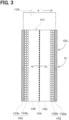
- the electrochemical cell 101 includes a working electrode 102, a counter electrode 103 and an insulating layer 104.
- the working electrode 102, the counter electrode 103 and the insulating layer 104 are each formed in a plate shape.
- the working electrode 102, the counter electrode 103 and the insulating layer 104 are illustrated to have distances therebetween, but actually, these components are arranged to be in contact with each other.
- the electrochemical cell 101 may be housed in a container (not shown).
- the container may define a gas inlet for introducing the CO 2 containing gas into the container and a gas outlet for discharging the CO 2 removed gas and CO 2 out of the container.
- the CO 2 recovery device 100 is configured to adsorb and desorb CO 2 through electrochemical reactions, thereby separating and recovering CO 2 from the CO 2 containing gas.
- the CO 2 recovery device 100 includes a power supply 105 that applies a predetermined voltage to the working electrode 102 and the counter electrode 103, and can change a potential difference between the working electrode 102 and the counter electrode 103.
- the working electrode 102 is a negative electrode
- the counter electrode 103 is a positive electrode.
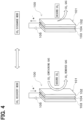
- the electrochemical cell 101 can be switched between a CO 2 recovery mode in which CO 2 is recovered at the working electrode 102 and a CO 2 discharge mode in which CO 2 is discharged from the working electrode 102 by changing the potential difference between the working electrode 102 and the counter electrode 103.
- the CO 2 recovery mode is a charging mode for charging the electrochemical cell 101
- the CO 2 discharge mode is a discharging mode for discharging the electrochemical cell 101.
- a first voltage V1 is applied between the working electrode 102 and the counter electrode 103, and electrons flows from the counter electrode 103 to the working electrode 102.
- the counter electrode potential is greater than the working electrode potential.
- the first voltage V1 is a potential difference obtained by subtracting the potential of the counter electrode 103 from the potential of the working electrode 102, the first voltage V1 can be set within a range of -0.5 to -2.0 V, for example.
- a second voltage V2 is applied between the working electrode 102 and the counter electrode 103, and electrons flows from the working electrode 102 to the counter electrode 103.
- the second voltage V2 is a voltage lower than the first voltage V1, and a magnitude relationship between the working electrode potential and the counter electrode potential is not limited. That is, in the CO 2 discharge mode, the working electrode potential may be lower than, equal to, or greater than the counter electrode potential.
- the working electrode 102 is provided with a working-electrode current collector 102a and a CO 2 adsorbent 102b.
- the working-electrode current collector 102a is a porous conductive material having pores through which gas containing CO 2 can pass.
- a carbonaceous material or a metal porous body can be used as the working-electrode current collector 102a.
- the carbonaceous material constituting the working-electrode current collector 102a may be, for example, carbon paper, carbon cloth, non-woven carbon mat, porous gas diffusion layer (GDL) and the like.
- the metal porous body constituting the working-electrode current collector 102a may be, for example, a metal mesh that is a metal (e.g., Al, Ni, etc.) formed into a mesh shape.
- the CO 2 adsorbent 102b is a made of material that can transfer electrons without changing its chemical skeleton when a negative potential is applied to the counter electrode 103.
- the CO 2 adsorbent 102b is made of a material in which, when receiving electrons from the counter electrode 103, the electric charge is delocalized in the entire material without concentrating on a specific element in its chemical structure. In other words, the CO 2 adsorbent 102b does not have a chemical structure that serves as an active site for adsorbing CO 2 in the material itself.
- the CO 2 adsorbent 102b of the present embodiment is a conductive material with a high specific surface area.
- a material that can be used as a carbon electrode such as carbon black, graphene, carbon nanotubes, activated carbon, Ketjen Black, or mesoporous carbon, can be used.
- an oxygen reduction reaction shown in the following reaction formula (1) and a carbonate ion generation reaction shown in the following reaction formula (2) proceed at the working electrode 102, and CO 2 is adsorbed to the working electrode 102.
- the oxygen reduction reaction triggers the CO 2 adsorption at the working electrode 102.
- O 2 contained in the CO 2 containing gas receives electrons and is reduced, thereby causing an oxygen reduction reaction.
- Superoxide O 2 - which is a type of active oxygen is formed by the oxygen reduction reaction.
- the active oxygen O 2 - generated in the oxygen reduction reaction is highly reactive, and oxidizes CO 2 to generate carbonate ions CO 3 2- , which are oxide ions of CO 2 , in the carbonate ion generation reaction.
- CO 2 is adsorbed onto the working electrode 102 in the form of carbonate ions including CO 3 2- . That is, at the working electrode 102, active oxygen O 2 - generated by the oxygen reduction reaction contributes to the CO 2 adsorption.
- the CO 2 adsorbent 102b is added with a binder.
- the binder is provided to hold the CO 2 adsorbent 102b on the working-electrode current collector 102a of the working electrode 102.
- the binder has an adhesive force and is provided between the CO 2 adsorbent 102b and the working-electrode current collector 102a.
- the binder may be a conductive resin.
- An epoxy resin containing Ag or the like as a conductive filler, a fluororesin such as polytetrafluoroethylene (PTFE) or polyvinylidene fluoride (PVDF), or the like can be used as the conductive resin.
- the binder can be brought into contact with the working-electrode current collector 102a including the CO 2 adsorbent 102b by using an organic solvent similarly to a conductive substance.
- a raw material of the binder and the CO 2 adsorbent 102b may be dispersed and mixed using a homogenizer or the like, and then the mixture may be pressure-bonded to the working-electrode current collector 102a or spray-coated on the working-electrode current collector 102a.
- the counter electrode 103 has a structure similar to the working electrode 102, and includes a counter-electrode current collector 103a and a counter-electrode active material 103b.
- the counter-electrode current collector 103a may use the same conductive material as the working-electrode current collector 102a, or may use a different material.
- the counter-electrode active material 103b is an auxiliary electroactive species that exchanges electrons with the CO 2 adsorbent 102b through a redox reaction.
- the counter-electrode active material 103b may be, for example, a metal complex that can receive and release electrons by changing a valence of a metal ion. Examples of such metal complex include cyclopentadienyl metal complexes such as ferrocene, nickelocene and cobaltocene, and porphyrin metal complexes.
- polyvinyl ferrocene shown below is used as the counter-electrode active material 103b.
- a conductive material and a binder are added to the counter-electrode active material 103b.
- the conductive material forms a conductive path to the counter-electrode active material 103b.
- the binder may be any material as long as it can hold the counter-electrode active material 103b on the counter-electrode current collector 103a and has conductivity.
- the conductive material of the counter electrode 103 may be, for example, a carbon material such as carbon nanotube, carbon black, or graphene.
- the binder of the counter electrode 103 may use the same material as the working electrode 102, or may use a different material.
- the insulating layer 104 is arranged between the working electrode 102 and the counter electrode 103, and is a separator that separates the working electrode 102 and the counter electrode 103 from each other.
- the insulating layer 104 prevents physical contact between the working electrode 102 and the counter electrode 103 and electrically insulates the working electrode 102 and the counter electrode 103 from each other.
- the insulating layer 104 has ion permeability.
- a porous body is used as the insulating layer 104.
- the insulating layer 104 may be, a cellulose membrane, a polymer, a composite material of a polymer and a ceramic, or the like.
- the working electrode 102 and the counter electrode 103 are disposed so as to sandwich an electrolyte 106.
- the electrolyte 106 is an ion conductive material provided between the working electrode 102 and the counter electrode 103.
- the electrolyte 106 is partitioned into a portion close to the working electrode 102 and a portion close to the counter electrode 103 by the insulating layer 104.
- the electrolyte 106 is in contact with the CO 2 adsorbent 102b.
- the ions contained in the electrolyte 106 promote electron attraction of the CO 2 adsorbent 102b when the CO 2 adsorbent 102b adsorbs CO 2 .
- an ionic liquid can be used as the electrolyte 106.
- the ionic liquid is a salt of a liquid having non-volatility under normal temperature and pressure.
- the ionic liquid may be gelled to prevent elution of the ionic liquid from the electrochemical cell 101.
- the electrolyte 106 is made of a material that satisfies at least one of requirements that the dissolved oxygen concentration is 0.2 cm 3 /cm 3 or less and the oxygen diffusion coefficient is 5 ⁇ 10 -7 cm -2 /s or less.
- CO 2 contained in the CO 2 containing gas dissolves in the electrolyte 106 and comes into contact with the CO 2 adsorbent 102b, and the CO 2 adsorbent 102b bonds with the CO 2 . Therefore, in order to promote contact of CO 2 with the CO 2 adsorbent 102b via the electrolyte 106, it is desirable to use, as the electrolyte 106, a material that has a large dissolved carbon dioxide concentration and has a large carbon dioxide diffusion coefficient.
- the electrolyte 106 is made of a material that has a dissolved carbon dioxide concentration of 1 ⁇ 10 -3 cm 3 /cm 3 or more and a carbon dioxide diffusion coefficient of 1 ⁇ 10 -7 cm -2 /s or more.
- the oxygen diffusion coefficient and the carbon dioxide diffusion coefficient can be measured by NMR methods.
- the measurement of the diffusion coefficients by the NMR method uses a pulsed magnetic field gradient (PFG) device.
- PFG pulsed magnetic field gradient
- Molecular diffusion is a phenomenon in which the position of a molecule changes due to translational motion.
- PFG pulsed magnetic field gradient
- By applying a pulsed magnetic field gradient to each position it is possible to imprint positional information onto a phase of a nuclear spin of atomic nuclei. Then, by analyzing a magnetic field gradient history before and after diffusion, the diffusion coefficients of the diffusing substances can be calculated.
- the dissolved oxygen concentration and the dissolved carbon dioxide concentration can be measured by a volumetric method using a gas burette and a mercury manometer.
- the amount of gas dissolved in the electrolyte 106 can be measured by measuring the volume and pressure of the gas in the gas burette when the electrolyte 106 and the gas reach solution equilibrium.
- the electrolyte 106 that satisfies the above-described requirements of the dissolved oxygen concentration, the oxygen diffusion coefficient, the dissolved carbon dioxide concentration, and the carbon dioxide diffusion coefficient, at least one of ionic liquids [TMPA][TFSI] and [P14][TFSI] shown below can be used.
- [TMPA][TFSI] and [P14][TFSI] may be used alone as the electrolyte 106 or a mixture of them may be used as the electrolyte 106. That is, the ionic liquid used as the electrolyte 106 contains at least one of [TMPA] and [P14] as a cation, and contains [TFSI] as an anion.
- the carbon dioxide recovery system 10 operates by alternately switching between the CO 2 recovery mode and the CO 2 discharge mode as shown in FIG. 4 .
- the operation of the carbon dioxide recovery system 10 is controlled by the controller 14.
- the CO 2 recovery mode will be described.
- the compressor 11 operates to supply CO 2 containing gas to the CO 2 recovery device 100.
- the voltage applied between the working electrode 102 and the counter electrode 103 is set to the first voltage V1.
- electron donation of the counter-electrode active material 103b of the counter electrode 103 and electron attraction of the CO 2 adsorbent 102b of the working electrode 102 can be realized at the same time.
- the counter-electrode active material 103b of the counter electrode 103 discharges electrons to be oxidized, and the electrons are supplied from the counter electrode 103 to the working electrode 102.
- the oxygen reduction reaction in which active oxygen O 2 - is generated from O 2 contained in the CO 2 containing gas and the carbonate ion generation reaction in which CO 2 contained in the CO 2 containing gas is oxidized by the active oxygen O 2 - to generate carbonate ions CO 3 2- proceed.
- the CO 2 contained in the CO 2 containing gas is adsorbed by the CO 2 adsorbent 102b.
- the CO 2 recovery device 100 can recover CO 2 from the CO 2 containing gas.
- the CO 2 removed gas is discharged from the CO 2 recovery device 100.
- the passage switching valve 12 switches the passage of exhaust gas toward the atmosphere, and the CO 2 removed gas from the CO 2 recovery device 100 is discharged to the atmosphere.
- the CO 2 discharge mode In the CO 2 discharge mode, the compressor 11 is stopped and supply of the CO 2 containing gas to the CO 2 recovery device 100 is stopped. In the CO 2 recovery device 100, a voltage applied between the working electrode 102 and the counter electrode 103 is set to the second voltage V2. As a result, electron donation of the CO 2 adsorbent 102b of the working electrode 102 and electron attraction of the counter-electrode active material 103b of the counter electrode 103 can be realized at the same time. The counter-electrode active material 103b of the counter electrode 103 receives electrons to be reduced.
- the CO 2 adsorbent 102b of the working electrode 102 discharges electrons. By discharging electrons, the CO 2 adsorbent 102b desorbs CO 2 .
- the CO 2 from the CO 2 adsorbent 102b is discharged from the CO 2 recovery device 100.
- the passage switching valve 12 switches the passage of the exhaust gas toward the CO 2 utilizing device 13, and the CO 2 discharged from the CO 2 recovery device 100 is supplied to the CO 2 utilizing device 13.
- FIG. 5 shows the change in the amount of electrons supplied from the counter electrode 103 to the working electrode 102 when the CO 2 recovery mode is repeatedly performed in the electrochemical cell 101 of the present embodiment.
- FIG. 6 shows the change in the amount of CO 2 adsorbed by the working electrode 102 when the CO 2 recovery mode is repeatedly performed in the electrochemical cell 101 of the present embodiment.
- FIG. 5 and FIG. 6 show the electron supply amount and the CO 2 adsorption amount of the electrochemical cell 101 using [TMPA][TFSI] as the electrolyte 106 of the present embodiment.
- FIG. 5 and FIG. 6 also show, as a comparative example, an electron supply amount and a CO 2 adsorption amount of an electrochemical cell using conventionally-used [BMIM][TFSI] as an electrolyte.
- the horizontal axis indicates the number of cycles the electrochemical cell 101 performs the CO 2 recovery mode.
- the vertical axis in FIG. 5 represents a ratio of the electron supply amount, which is a ratio of change in the electron supply amount when the electron supply amount in the first cycle of the CO 2 recovery mode is set to 1.0 (100%).
- the vertical axis in FIG. 6 represents a ratio of the CO 2 adsorption amount, which is a ratio of change in the CO 2 adsorption amount when the CO 2 adsorption amount in the first cycle of the CO 2 recovery mode is set to 1.0 (100%).
- the electron supply amount decreases in both the present embodiment and the comparative example.
- the number of CO 2 recovery cycles exceeds five, a decrease rate in the electron supply amount is smaller in the present embodiment than in the comparative example.
- the electrochemical cell 101 of the present embodiment is can restrict the decrease in the electron supply amount more effectively than the comparative example.
- the CO 2 adsorption amount decreases in both the present embodiment and the comparative example.
- the number of CO 2 recovery cycles exceeds eleven, a decrease rate in the CO 2 adsorption amount is smaller in the present embodiment than in the comparative example.
- the electrochemical cell 101 of the present embodiment can restrict the decrease in the CO 2 adsorption amount more effectively than the comparative example.
- the CO 2 recovery device 100 of the present embodiment described above uses the electrolyte 106 that has the small dissolved oxygen concentration and the small oxygen diffusion coefficient. Therefore, when the CO 2 adsorbent 102b having no active sites is used, it is possible to restrict the active oxygen generated at the working electrode 102 from diffusing to the counter electrode 103 while allowing the generation of active oxygen that contributes to CO 2 adsorption. This makes it possible to restrict the counter electrode active material 103b from being oxidized and decomposed by active oxygen, to restrict the decrease in the amount of electrons supplied from the counter electrode 103 to the working electrode 102, and to restrict the decrease in the amount of CO 2 adsorbed by the working electrode 102.
- At least one of [TMPA][TFSI] and [P14][TFSI] is used as the electrolyte 106.
- These ionic liquids are substances with the small dissolved oxygen concentration and the small oxygen diffusion coefficient, and can effectively restrict active oxygen generated at the working electrode 102 from diffusing to the counter electrode 103.
- an antioxidant is added to the counter-electrode active material 103b to prevent oxidation of the counter-electrode active material 103b.
- the antioxidant is a substance that reacts preferentially with active oxygen rather than with the counter-electrode active material 103b.
- a phenol having a hydroxy group on the aromatic substituent is used as the antioxidant.
- Irganox 1010 As such a phenol-based antioxidant, Irganox 1010 manufactured by BASF Japan Ltd., can be used. Irganox 1010 is pentaerythritol tetrakis[3-(3',5'-di-t-butyl-4'-hydroxyphenyl)propionic acid] with the molecular formula C 73 H 108 O 12 and has the following structural formula:
- the counter-electrode active material 103b and the antioxidant are mixed in a mass ratio of 1:1. That is, the mixture of counter-electrode active material 103b and the antioxidant contains 50 wt % of the antioxidant.
- the antioxidant by adding the antioxidant to the counter-electrode active material 103b, even if active oxygen generated in the working electrode 102 diffuses to the counter electrode 103, the antioxidant reacts preferentially with the active oxygen.
- the reaction between active oxygen and the counter-electrode active material 103b can be restricted, the oxidative decomposition of the counter-electrode active material 103b can be restricted, the decrease in the amount of electrons supplied from the counter electrode 103 to the working electrode 102 can be restricted, and the decrease in the amount of CO 2 adsorption by the working electrode 102 can be restricted.
- the configuration of the second embodiment in which the antioxidant is added to the counter-electrode active material 103b is not limited to a configuration using the electrolyte 106 having the small dissolved oxygen concentration and the small oxygen diffusion coefficient, but can also be applied to a configuration using a conventional electrolyte.
- the decomposition products of the counter-electrode active material 103b do not permeate the insulating layer 104. This makes it possible to prevent the decomposition products of the counter-electrode active material 103b from permeating through the insulating layer 104 and diffusing from the counter electrode 103 to the working electrode 102, and allows the decomposition products of the counter-electrode active material 103b to be present only in a portion of the electrolyte 106 separated by the insulating layer 104 and adjacent to the counter electrode 103.
- the portion of the electrolyte 106 separated by the insulating layer 104 and adjacent to the counter electrode 103 can be saturated with the decomposition products, further decomposition of the counter-electrode active material 103b can be restricted, and the decrease in the amount of CO 2 adsorbed by the working electrode 102 can be restricted.
- the counter electrode 103 does not include the counter-electrode active material 103b.
- the counter-electrode active material 103b is an electroactive species that receives and releases electrons by a redox reaction.
- the counter-electrode current collector 103a constituting the counter electrode 103 is made of a carbonaceous material or a porous metal.
- the counter-electrode active material 103b corresponds to an active material of the present disclosure.
- the electrochemical cell 101 when a voltage is applied between the working electrode 102 and the counter electrode 103, electrons and ions contained in the electrolyte 106 form an electric double layer.
- the CO 2 recovery mode when cations of the electrolyte 106 move to a surface of the working electrode 102 and anions of the electrolyte 106 move to a surface of the counter electrode 103, a potential difference is formed between the vicinity of the respective surfaces, and electrons are supplied from the counter electrode 103 to the working electrode 102.
- anions of the electrolyte 106 move to the surface of the working electrode 102, cations of the electrolyte 106 move to the surface of the counter electrode 103, and electrons are supplied from the working electrode 102 to the counter electrode 103.
- the voltage applied between the working electrode 102 and the counter electrode 103 in the CO 2 adsorption mode is made larger than in each of the above embodiments in which the counter-electrode active material 103b is provided.
- the potential difference between the working electrode potential and the counter electrode potential is increased toward the negative side, so that the potential difference obtained by subtracting the potential of the counter electrode 103 from the potential of the working electrode 102 is equal to or less than a predetermined value (for example, -2.0 V or less).
- the generation of active oxygen that contributes to CO 2 adsorption is allowed, and even if the active oxygen reaches the counter electrode 103, the counter-electrode active material is not oxidized and decomposed. Therefore, it is possible to restrict the decrease in the CO 2 adsorption amount due to oxidative decomposition of the counter-electrode active material.
- the carbonaceous material when a carbonaceous material is used as the counter-electrode current collector 103a in the fourth embodiment, the carbonaceous material may be oxidized by the active oxygen, and the amount of electrons supplied from the counter electrode 103 to the working electrode 102 may decrease. Therefore, by using the electrolyte 106 with the small dissolved oxygen concentration and the small oxygen diffusion coefficient, the diffusion of the active oxygen from the working electrode 102 to the counter electrode 103 can be restricted, and the oxidation of the carbonaceous material constituting the counter-electrode current collector 103a can be restricted.
- the carbon dioxide recovery system disclosed in the present specification has the following features.
- a carbon dioxide recovery system is for separating CO 2 from a CO 2 containing gas that contains CO 2 through electrochemical reactions and includes an electrochemical cell (101) in which a working electrode (102) including a CO 2 adsorbent (102b) and a counter electrode (103) are disposed to sandwich an electrolyte (106).
- the CO 2 adsorbent is configured to absorb CO 2 in response to electrons being supplied from the counter electrode to the working electrode due to a voltage applied between the working electrode and the counter electrode.
- the electrolyte is made of a material that satisfies at least one of requirements that a dissolved oxygen concentration is 0.2 cm 3 /cm 3 or less and an oxygen diffusion coefficient is 5 ⁇ 10 -7 cm -2 /s or less.
- the electrolyte has a dissolved carbon dioxide concentration of 1 ⁇ 10 -3 cm 3 /cm 3 or more.
- the electrolyte has a carbon dioxide diffusion coefficient of 1 ⁇ 10 -7 cm -2 /s or more.
- the electrolyte is at least one of [TMPA][TFSI] and [P14][TFSI].
- the counter electrode includes a counter-electrode active material, and the counter-electrode active material is added with an antioxidant that reacts more preferentially with active oxygen than the counter-electrode active material.
- a carbon dioxide recovery system is for separating CO 2 from a CO 2 containing gas that contains CO 2 through electrochemical reactions, and includes an electrochemical cell (101) in which a working electrode (102) including a CO 2 adsorbent (102b) and a counter electrode (103) are disposed to sandwich an electrolyte (106).
- the CO 2 adsorbent is configured to absorb CO 2 in response to electrons being supplied from the counter electrode to the working electrode due to a voltage applied between the working electrode and the counter electrode.
- the counter electrode includes a counter-electrode active material.
- the counter-electrode active material is added with an antioxidant that reacts more preferentially with active oxygen than the counter-electrode active material.
- the antioxidant is a phenol.
- the antioxidant is pentaerythritol tetrakis[3-(3',5'-di-t-butyl-4'-hydroxyphenyl)propionic acid].
- the carbon dioxide recovery system further includes an insulating layer (104) disposed between the working electrode and the counter electrode to electrically insulate the working electrode from the counter electrode.
- the insulating layer is a made of a porous body, and a pore size of the porous body is smaller than a size of a decomposition product generated by oxidative decomposition of the counter-electrode active material by the active oxygen.
- the counter electrode includes no active material
- the CO 2 adsorbent is configured to adsorb CO 2 in response to the electrons being supplied from the counter electrode to the working electrode due to the voltage applied between the working electrode and the counter electrode so that a potential difference obtained by subtracting a potential of the counter electrode from a potential of the working electrode is equal to or less than a predetermined value.
- a carbon dioxide recovery system is for separating CO 2 from a CO 2 containing gas that contains CO 2 through electrochemical reactions, and includes an electrochemical cell (101) in which a working electrode (102) including a CO 2 adsorbent (102b) and a counter electrode (103) are disposed to sandwich and an electrolyte (106).
- the counter electrode includes no active material, and the CO 2 adsorbent is configured to adsorb CO 2 in response to electrons being supplied from the counter electrode to the working electrode due to a voltage applied between the working electrode and the counter electrode so that a potential difference obtained by subtracting a potential of the counter electrode from a potential of the working electrode is equal to or less than a predetermined value.
Landscapes
- Chemical & Material Sciences (AREA)
- Engineering & Computer Science (AREA)
- Chemical Kinetics & Catalysis (AREA)
- Oil, Petroleum & Natural Gas (AREA)
- Organic Chemistry (AREA)
- Analytical Chemistry (AREA)
- General Chemical & Material Sciences (AREA)
- Environmental & Geological Engineering (AREA)
- Health & Medical Sciences (AREA)
- Inorganic Chemistry (AREA)
- Biomedical Technology (AREA)
- Electrochemistry (AREA)
- Carbon And Carbon Compounds (AREA)
- Treating Waste Gases (AREA)
- Gas Separation By Absorption (AREA)
Abstract
A carbon dioxide recovery system is for separating CO2 from a CO2 containing gas that contains CO2 through electrochemical reactions and includes an electrochemical cell (101) in which a working electrode (102) including a CO2 adsorbent (102b) and a counter electrode (103) are disposed to sandwich an electrolyte (106). The CO2 adsorbent is configured to absorb CO2 in response to electrons being supplied from the counter electrode to the working electrode due to a voltage applied between the working electrode and the counter electrode. The electrolyte is made of a material that satisfies at least one of requirements that a dissolved oxygen concentration is 0.2 cm3/cm3 or less and an oxygen diffusion coefficient is 5×10⁻⁷ cm-2/s or less.
Description
- This application is based on
Japanese Patent Application No. 2022-104810 filed on June 29, 2022 - The present disclosure relates to carbon dioxide recovery systems that recover CO2 from CO2 containing gas.
-
Patent Literature 1 proposes a method for separating CO2 from a CO2 containing gas through electrochemical reactions. In a gas separation system ofPatent Literature 1, a CO2 adsorbent capable of adsorbing CO2 is provided on a working electrode of an electrochemical cell. The CO2 adsorbent is an electroactive species, and the adsorption and discharge of CO2 by the CO2 adsorbent can be switched by changing a potential difference between the working electrode and a counter electrode. - Patent Literature 1:
JP 2018-533470 A - The present inventors have found that when a CO2 adsorbent having no active sites is used in a working electrode of an electrochemical cell, the amount of CO2 adsorption decreases for the following reasons.
- That is, when a CO2 adsorbent having no active sites is used, active oxygen O2 - generated from O2 contained in the CO2 containing gas contributes to the adsorption of CO2 at the working electrode. On the other hand, when the active oxygen generated at the working electrode diffuses to a counter electrode, a counter-electrode active material is oxidized and decomposed by the active oxygen, and the amount of electrons supplied from the counter electrode to the working electrode decreases. As a result, the amount of CO2 adsorbed at the working electrode decreases.
- In view of the above points, an object of the present disclosure is to provide a carbon dioxide recovery system capable of restricting a decrease in the amount of CO2 adsorption in an electrochemical cell.
- In order to achieve the above object, each of carbon dioxide recovery systems of the present disclosure includes an electrochemical cell in which a working electrode including a CO2 adsorbent and a counter electrode are disposed to sandwich an electrolyte.
- In a carbon dioxide recovery system according to a first aspect of the present disclosure, the CO2 adsorbent is configured to absorb CO2 in response to electrons being supplied from the counter electrode to the working electrode due to a voltage applied between the working electrode and the counter electrode. The electrolyte is made of a material that satisfies at least one of requirements that a dissolved oxygen concentration is 0.2 cm3/cm3 or less and an oxygen diffusion coefficient is 5×10⁻⁷ cm-2/s or less.
- In a carbon dioxide recovery system according to a second aspect of the present disclosure, the CO2 adsorbent is configured to absorb CO2 in response to electrons being supplied from the counter electrode to the working electrode due to a voltage applied between the working electrode and the counter electrode. The counter electrode includes a counter-electrode active material, and the counter-electrode active material is added with an antioxidant that reacts more preferentially with active oxygen than the counter-electrode active material.
- In a carbon dioxide recovery system according to a third aspect of the present disclosure, the counter electrode includes no active material. The CO2 adsorbent is configured to adsorb CO2 in response to electrons being supplied from the counter electrode to the working electrode due to a voltage applied between the working electrode and the counter electrode so that a potential difference obtained by subtracting a potential of the counter electrode from a potential of the working electrode is equal to or less than a predetermined value.
- According to the carbon dioxide recovery systems of the present disclosure, a decrease in the amount of electrons supplied from the counter electrode to the working electrode can be restricted, and a decrease in the amount of CO2 adsorption by the working electrode can be restricted.
-
-
FIG. 1 is a diagram illustrating a carbon dioxide recovery system of a first embodiment. -
FIG. 2 is a diagram illustrating a CO2 recovery device. -
FIG. 3 is a cross-sectional view of an electrochemical cell of the first embodiment. -
FIG. 4 is a diagram for explaining a CO2 recovery mode and a CO2 discharge mode of the CO2 recovery device. -
FIG. 5 is a graph showing a change in an electron supply amount in the electrochemical cell of the first embodiment. -
FIG. 6 is a graph showing a change in a CO2 adsorption amount in the electrochemical cell of the first embodiment. -
FIG. 7 is a cross-sectional view of an electrochemical cell of a fourth embodiment. - The following will describe embodiments for carrying out the present disclosure with reference to the drawings. In each embodiment, portions corresponding to the elements described in the preceding embodiments are denoted by the same reference numerals, and redundant explanation may be omitted. When only a part of a configuration is described in an embodiment, another preceding embodiment may be applied to the other parts of the configuration. The parts may be combined even if it is not explicitly described that the parts can be combined. The embodiments may be partially combined even if it is not explicitly described that the embodiments can be combined, provided there is no harm in the combination.
- The following describes a first embodiment of the present disclosure with reference to the drawings. As shown in
FIG. 1 , a carbondioxide recovery system 10 of the present embodiment includes acompressor 11, a CO2 recovery device 100, apassage switching valve 12, a CO2 utilizing device 13, and acontroller 14. - The
compressor 11 pumps CO2 containing gas to the CO2 recovery device 100. The CO2 containing gas is a mixed gas that contains CO2 and a gas other than CO2, such as air. The CO2 containing gas contains at least O2 as the gas other than CO2. - The CO2 recovery device 100 is a device that separates CO2 from the CO2 containing gas and recovers CO2. The CO2 recovery device 100 discharges a CO2 removed gas that is a gas after CO2 is recovered from the CO2 containing gas, or CO2 recovered from the CO2 containing gas. The configuration of the CO2 recovery device 100 will be described in detail later.
- The
passage switching valve 12 is a three-way valve that switches a passage of exhaust gas from the CO2 recovery device 100. Thepassage switching valve 12 switches the passage of the exhaust gas toward the atmosphere when the CO2 removed gas is discharged from the CO2 recovery device 100, and switches the passage of the exhaust gas toward the CO2 utilizing device 13 when CO2 is discharged from the CO2 recovery device 100. - The CO2 utilizing device 13 is a device that utilizes CO2. The CO2 utilizing device 13 may be a storage tank for storing CO2 or a conversion device for converting CO2 into fuel. As the conversion device, a device that converts CO2 into a hydrocarbon fuel such as methane can be used. The hydrocarbon fuel may be gaseous fuel at normal temperature and pressure, or may be liquid fuel at normal temperature and pressure.
- The
controller 14 includes a well-known microcontroller including a central processing device (CPU), a read only memory (ROM), a random access memory (RAM) and the like, and peripheral circuits thereof. Thecontroller 14 performs various calculations and processes based on control programs stored in the ROM, and controls actuations of various devices connected to an output side of thecontroller 14. Thecontroller 14 of the present embodiment performs an operation control of thecompressor 11, an operation control of the CO2 recovery device 100, a passage switching control of thepassage switching valve 12 and the like. - Next, the CO2 recovery device 100 will be described with reference to
FIG. 2 . As shown inFIG. 2 , the CO2 recovery device 100 is provided with anelectrochemical cell 101. Theelectrochemical cell 101 includes a workingelectrode 102, acounter electrode 103 and aninsulating layer 104. In the example shown inFIG. 2 , the workingelectrode 102, thecounter electrode 103 and theinsulating layer 104 are each formed in a plate shape. InFIG. 2 , the workingelectrode 102, thecounter electrode 103 and theinsulating layer 104 are illustrated to have distances therebetween, but actually, these components are arranged to be in contact with each other. - The
electrochemical cell 101 may be housed in a container (not shown). The container may define a gas inlet for introducing the CO2 containing gas into the container and a gas outlet for discharging the CO2 removed gas and CO2 out of the container. - The CO2 recovery device 100 is configured to adsorb and desorb CO2 through electrochemical reactions, thereby separating and recovering CO2 from the CO2 containing gas. The CO2 recovery device 100 includes a
power supply 105 that applies a predetermined voltage to the workingelectrode 102 and thecounter electrode 103, and can change a potential difference between the workingelectrode 102 and thecounter electrode 103. The workingelectrode 102 is a negative electrode, and thecounter electrode 103 is a positive electrode. - The
electrochemical cell 101 can be switched between a CO2 recovery mode in which CO2 is recovered at the workingelectrode 102 and a CO2 discharge mode in which CO2 is discharged from the workingelectrode 102 by changing the potential difference between the workingelectrode 102 and thecounter electrode 103. The CO2 recovery mode is a charging mode for charging theelectrochemical cell 101, and the CO2 discharge mode is a discharging mode for discharging theelectrochemical cell 101. - In the CO2 recovery mode, a first voltage V1 is applied between the working
electrode 102 and thecounter electrode 103, and electrons flows from thecounter electrode 103 to the workingelectrode 102. At the first voltage V1, the counter electrode potential is greater than the working electrode potential. When the first voltage V1 is a potential difference obtained by subtracting the potential of thecounter electrode 103 from the potential of the workingelectrode 102, the first voltage V1 can be set within a range of -0.5 to -2.0 V, for example. - In the CO2 discharge mode, a second voltage V2 is applied between the working
electrode 102 and thecounter electrode 103, and electrons flows from the workingelectrode 102 to thecounter electrode 103. The second voltage V2 is a voltage lower than the first voltage V1, and a magnitude relationship between the working electrode potential and the counter electrode potential is not limited. That is, in the CO2 discharge mode, the working electrode potential may be lower than, equal to, or greater than the counter electrode potential. - As shown in
FIG. 3 , the workingelectrode 102 is provided with a working-electrodecurrent collector 102a and a CO2 adsorbent 102b. - The working-electrode
current collector 102a is a porous conductive material having pores through which gas containing CO2 can pass. As the working-electrodecurrent collector 102a, for example, a carbonaceous material or a metal porous body can be used. The carbonaceous material constituting the working-electrodecurrent collector 102a may be, for example, carbon paper, carbon cloth, non-woven carbon mat, porous gas diffusion layer (GDL) and the like. The metal porous body constituting the working-electrodecurrent collector 102a may be, for example, a metal mesh that is a metal (e.g., Al, Ni, etc.) formed into a mesh shape. - The CO2 adsorbent 102b adsorbs CO2 by receiving electrons, and desorbs the adsorbed CO2 by releasing electrons. The CO2 adsorbent 102b is made of a material whose chemical skeleton does not change when adsorbing CO2.
- In the present embodiment, the CO2 adsorbent 102b is a made of material that can transfer electrons without changing its chemical skeleton when a negative potential is applied to the
counter electrode 103. The CO2 adsorbent 102b is made of a material in which, when receiving electrons from thecounter electrode 103, the electric charge is delocalized in the entire material without concentrating on a specific element in its chemical structure. In other words, the CO2 adsorbent 102b does not have a chemical structure that serves as an active site for adsorbing CO2 in the material itself. - When the first voltage V1 is applied between the working
electrode 102 and thecounter electrode 103, electrons flow from thecounter electrode 103 to the workingelectrode 102, and the CO2 adsorbent 102b takes in the electrons and adsorbs CO2. When the second voltage V2 is applied between the workingelectrode 102 and thecounter electrode 103, electrons flow from the workingelectrode 102 to thecounter electrode 103, and the CO2 adsorbent 102b discharges the electrons and desorbs CO2. - The CO2 adsorbent 102b of the present embodiment is a conductive material with a high specific surface area. As the material constituting the CO2 adsorbent 102b and having high specific surface area, for example, a material that can be used as a carbon electrode, such as carbon black, graphene, carbon nanotubes, activated carbon, Ketjen Black, or mesoporous carbon, can be used.
- In the CO2 recovery mode, an oxygen reduction reaction shown in the following reaction formula (1) and a carbonate ion generation reaction shown in the following reaction formula (2) proceed at the working
electrode 102, and CO2 is adsorbed to the workingelectrode 102. In other words, the oxygen reduction reaction triggers the CO2 adsorption at the workingelectrode 102.
O2+2e-→O2- (1)
O2 - + CO2 → 1/2O2 + CO3 2- (2)
- At the working
electrode 102, O2 contained in the CO2 containing gas receives electrons and is reduced, thereby causing an oxygen reduction reaction. Superoxide O2 -, which is a type of active oxygen is formed by the oxygen reduction reaction. The active oxygen O2 - generated in the oxygen reduction reaction is highly reactive, and oxidizes CO2 to generate carbonate ions CO3 2-, which are oxide ions of CO2, in the carbonate ion generation reaction. At the working electrode, CO2 is adsorbed onto the workingelectrode 102 in the form of carbonate ions including CO3 2-. That is, at the workingelectrode 102, active oxygen O2 - generated by the oxygen reduction reaction contributes to the CO2 adsorption. - The CO2 adsorbent 102b is added with a binder. The binder is provided to hold the CO2 adsorbent 102b on the working-electrode
current collector 102a of the workingelectrode 102. The binder has an adhesive force and is provided between the CO2 adsorbent 102b and the working-electrodecurrent collector 102a. - The binder may be a conductive resin. An epoxy resin containing Ag or the like as a conductive filler, a fluororesin such as polytetrafluoroethylene (PTFE) or polyvinylidene fluoride (PVDF), or the like can be used as the conductive resin.
- The binder can be brought into contact with the working-electrode
current collector 102a including the CO2 adsorbent 102b by using an organic solvent similarly to a conductive substance. Alternatively, a raw material of the binder and the CO2 adsorbent 102b may be dispersed and mixed using a homogenizer or the like, and then the mixture may be pressure-bonded to the working-electrodecurrent collector 102a or spray-coated on the working-electrodecurrent collector 102a. - As shown in
FIG. 3 , thecounter electrode 103 has a structure similar to the workingelectrode 102, and includes a counter-electrodecurrent collector 103a and a counter-electrodeactive material 103b. - The counter-electrode
current collector 103a may use the same conductive material as the working-electrodecurrent collector 102a, or may use a different material. - The counter-electrode
active material 103b is an auxiliary electroactive species that exchanges electrons with the CO2 adsorbent 102b through a redox reaction. The counter-electrodeactive material 103b may be, for example, a metal complex that can receive and release electrons by changing a valence of a metal ion. Examples of such metal complex include cyclopentadienyl metal complexes such as ferrocene, nickelocene and cobaltocene, and porphyrin metal complexes. In the present embodiment, polyvinyl ferrocene shown below is used as the counter-electrodeactive material 103b.

active material 103b. The conductive material forms a conductive path to the counter-electrodeactive material 103b. The binder may be any material as long as it can hold the counter-electrodeactive material 103b on the counter-electrodecurrent collector 103a and has conductivity. The conductive material of thecounter electrode 103 may be, for example, a carbon material such as carbon nanotube, carbon black, or graphene. The binder of thecounter electrode 103 may use the same material as the workingelectrode 102, or may use a different material. - The insulating
layer 104 is arranged between the workingelectrode 102 and thecounter electrode 103, and is a separator that separates the workingelectrode 102 and thecounter electrode 103 from each other. The insulatinglayer 104 prevents physical contact between the workingelectrode 102 and thecounter electrode 103 and electrically insulates the workingelectrode 102 and thecounter electrode 103 from each other. - The insulating
layer 104 has ion permeability. In the present embodiment, a porous body is used as the insulatinglayer 104. The insulatinglayer 104 may be, a cellulose membrane, a polymer, a composite material of a polymer and a ceramic, or the like. - In the
electrochemical cell 101, the workingelectrode 102 and thecounter electrode 103 are disposed so as to sandwich anelectrolyte 106. Theelectrolyte 106 is an ion conductive material provided between the workingelectrode 102 and thecounter electrode 103. Theelectrolyte 106 is partitioned into a portion close to the workingelectrode 102 and a portion close to thecounter electrode 103 by the insulatinglayer 104. - The
electrolyte 106 is in contact with the CO2 adsorbent 102b. The ions contained in theelectrolyte 106 promote electron attraction of the CO2 adsorbent 102b when the CO2 adsorbent 102b adsorbs CO2. - As the
electrolyte 106, for example, an ionic liquid can be used. The ionic liquid is a salt of a liquid having non-volatility under normal temperature and pressure. When the ionic liquid is used as theelectrolyte 106, the ionic liquid may be gelled to prevent elution of the ionic liquid from theelectrochemical cell 101. - In the CO2 recovery mode, when O2 contained in the CO2 containing gas dissolves in the
electrolyte 106 and comes into contact with the CO2 adsorbent 102b, active oxygen O2 - is generated from O2, and the active oxygen generated at the workingelectrode 102 diffuses to thecounter electrode 103. For this reason, in order to restrict O2 from coming into contact with the CO2 adsorbent 102b via theelectrolyte 106 and to restrict the active oxygen from diffusing from the workingelectrode 102 to thecounter electrode 103, it is desirable to use, as theelectrolyte 106, a material that has a small dissolved oxygen concentration and a small oxygen diffusion coefficient. In the present embodiment, theelectrolyte 106 is made of a material that satisfies at least one of requirements that the dissolved oxygen concentration is 0.2 cm3/cm3 or less and the oxygen diffusion coefficient is 5×10⁻⁷ cm-2/s or less. - On the other hand, in the CO2 recovery mode, CO2 contained in the CO2 containing gas dissolves in the
electrolyte 106 and comes into contact with the CO2 adsorbent 102b, and the CO2 adsorbent 102b bonds with the CO2. Therefore, in order to promote contact of CO2 with the CO2 adsorbent 102b via theelectrolyte 106, it is desirable to use, as theelectrolyte 106, a material that has a large dissolved carbon dioxide concentration and has a large carbon dioxide diffusion coefficient. In the present embodiment, theelectrolyte 106 is made of a material that has a dissolved carbon dioxide concentration of 1×10⁻³ cm3/cm3 or more and a carbon dioxide diffusion coefficient of 1×10⁻⁷ cm-2/s or more. - The oxygen diffusion coefficient and the carbon dioxide diffusion coefficient can be measured by NMR methods. The measurement of the diffusion coefficients by the NMR method uses a pulsed magnetic field gradient (PFG) device. Molecular diffusion is a phenomenon in which the position of a molecule changes due to translational motion. By applying a pulsed magnetic field gradient to each position, it is possible to imprint positional information onto a phase of a nuclear spin of atomic nuclei. Then, by analyzing a magnetic field gradient history before and after diffusion, the diffusion coefficients of the diffusing substances can be calculated.
- The dissolved oxygen concentration and the dissolved carbon dioxide concentration can be measured by a volumetric method using a gas burette and a mercury manometer. In the volumetric method using a gas burette and a mercury manometer, the amount of gas dissolved in the
electrolyte 106 can be measured by measuring the volume and pressure of the gas in the gas burette when theelectrolyte 106 and the gas reach solution equilibrium. - As the
electrolyte 106 that satisfies the above-described requirements of the dissolved oxygen concentration, the oxygen diffusion coefficient, the dissolved carbon dioxide concentration, and the carbon dioxide diffusion coefficient, at least one of ionic liquids [TMPA][TFSI] and [P14][TFSI] shown below can be used.

electrolyte 106 or a mixture of them may be used as theelectrolyte 106. That is, the ionic liquid used as theelectrolyte 106 contains at least one of [TMPA] and [P14] as a cation, and contains [TFSI] as an anion. - Next, an operation of the carbon
dioxide recovery system 10 of the present embodiment will be described. The carbondioxide recovery system 10 operates by alternately switching between the CO2 recovery mode and the CO2 discharge mode as shown inFIG. 4 . The operation of the carbondioxide recovery system 10 is controlled by thecontroller 14. - First, the CO2 recovery mode will be described. In the CO2 recovery mode, the
compressor 11 operates to supply CO2 containing gas to the CO2 recovery device 100. In the CO2 recovery device 100, the voltage applied between the workingelectrode 102 and thecounter electrode 103 is set to the first voltage V1. As a result, electron donation of the counter-electrodeactive material 103b of thecounter electrode 103 and electron attraction of the CO2 adsorbent 102b of the workingelectrode 102 can be realized at the same time. The counter-electrodeactive material 103b of thecounter electrode 103 discharges electrons to be oxidized, and the electrons are supplied from thecounter electrode 103 to the workingelectrode 102. - In the working
electrode 102, the oxygen reduction reaction in which active oxygen O2 - is generated from O2 contained in the CO2 containing gas and the carbonate ion generation reaction in which CO2 contained in the CO2 containing gas is oxidized by the active oxygen O2 - to generate carbonate ions CO3 2- proceed. The CO2 contained in the CO2 containing gas is adsorbed by the CO2 adsorbent 102b. Thus, the CO2 recovery device 100 can recover CO2 from the CO2 containing gas. - In the CO2 recovery mode, when O2 contained in the CO2 containing gas receives electrons at the working
electrode 102, active oxygen O2 - is generated. In the present embodiment, theelectrolyte 106 having the small dissolved oxygen concentration and the small oxygen diffusion coefficient is used. Therefore, while allowing the generation of active oxygen O2 - that contributes to CO2 adsorption at the workingelectrode 102, the diffusion of the active oxygen to thecounter electrode 103 side can be suppressed. - After the CO2 is recovered by the CO2 recovery device 100, the CO2 removed gas is discharged from the CO2 recovery device 100. The
passage switching valve 12 switches the passage of exhaust gas toward the atmosphere, and the CO2 removed gas from the CO2 recovery device 100 is discharged to the atmosphere. - Next, the CO2 discharge mode will be described. In the CO2 discharge mode, the
compressor 11 is stopped and supply of the CO2 containing gas to the CO2 recovery device 100 is stopped. In the CO2 recovery device 100, a voltage applied between the workingelectrode 102 and thecounter electrode 103 is set to the second voltage V2. As a result, electron donation of the CO2 adsorbent 102b of the workingelectrode 102 and electron attraction of the counter-electrodeactive material 103b of thecounter electrode 103 can be realized at the same time. The counter-electrodeactive material 103b of thecounter electrode 103 receives electrons to be reduced. - The CO2 adsorbent 102b of the working
electrode 102 discharges electrons. By discharging electrons, the CO2 adsorbent 102b desorbs CO2. - The CO2 from the CO2 adsorbent 102b is discharged from the CO2 recovery device 100. The
passage switching valve 12 switches the passage of the exhaust gas toward the CO2 utilizing device 13, and the CO2 discharged from the CO2 recovery device 100 is supplied to the CO2 utilizing device 13. - The following describes an electron supply amount and a CO2 adsorption amount of the
electrochemical cell 101 of the present embodiment.FIG. 5 shows the change in the amount of electrons supplied from thecounter electrode 103 to the workingelectrode 102 when the CO2 recovery mode is repeatedly performed in theelectrochemical cell 101 of the present embodiment.FIG. 6 shows the change in the amount of CO2 adsorbed by the workingelectrode 102 when the CO2 recovery mode is repeatedly performed in theelectrochemical cell 101 of the present embodiment. -
FIG. 5 and FIG. 6 show the electron supply amount and the CO2 adsorption amount of theelectrochemical cell 101 using [TMPA][TFSI] as theelectrolyte 106 of the present embodiment.FIG. 5 and FIG. 6 also show, as a comparative example, an electron supply amount and a CO2 adsorption amount of an electrochemical cell using conventionally-used [BMIM][TFSI] as an electrolyte. - In
FIG. 5 and FIG. 6 , the horizontal axis indicates the number of cycles theelectrochemical cell 101 performs the CO2 recovery mode. The vertical axis inFIG. 5 represents a ratio of the electron supply amount, which is a ratio of change in the electron supply amount when the electron supply amount in the first cycle of the CO2 recovery mode is set to 1.0 (100%). The vertical axis inFIG. 6 represents a ratio of the CO2 adsorption amount, which is a ratio of change in the CO2 adsorption amount when the CO2 adsorption amount in the first cycle of the CO2 recovery mode is set to 1.0 (100%). - As shown in
FIG. 5 , when the CO2 recovery mode is repeated, the electron supply amount decreases in both the present embodiment and the comparative example. When the number of CO2 recovery cycles exceeds five, a decrease rate in the electron supply amount is smaller in the present embodiment than in the comparative example. In other words, it is understood that theelectrochemical cell 101 of the present embodiment is can restrict the decrease in the electron supply amount more effectively than the comparative example. - As shown in
FIG. 6 , when the CO2 recovery mode is repeated, the CO2 adsorption amount decreases in both the present embodiment and the comparative example. When the number of CO2 recovery cycles exceeds eleven, a decrease rate in the CO2 adsorption amount is smaller in the present embodiment than in the comparative example. In other words, it is understood that theelectrochemical cell 101 of the present embodiment can restrict the decrease in the CO2 adsorption amount more effectively than the comparative example. - The CO2 recovery device 100 of the present embodiment described above uses the
electrolyte 106 that has the small dissolved oxygen concentration and the small oxygen diffusion coefficient. Therefore, when the CO2 adsorbent 102b having no active sites is used, it is possible to restrict the active oxygen generated at the workingelectrode 102 from diffusing to thecounter electrode 103 while allowing the generation of active oxygen that contributes to CO2 adsorption. This makes it possible to restrict the counter electrodeactive material 103b from being oxidized and decomposed by active oxygen, to restrict the decrease in the amount of electrons supplied from thecounter electrode 103 to the workingelectrode 102, and to restrict the decrease in the amount of CO2 adsorbed by the workingelectrode 102. - In the present embodiment, at least one of [TMPA][TFSI] and [P14][TFSI] is used as the
electrolyte 106. These ionic liquids are substances with the small dissolved oxygen concentration and the small oxygen diffusion coefficient, and can effectively restrict active oxygen generated at the workingelectrode 102 from diffusing to thecounter electrode 103. - The following describes a second embodiment of the present disclosure. Hereinafter, only portions different from the first embodiment are described.
- In the second embodiment, an antioxidant is added to the counter-electrode
active material 103b to prevent oxidation of the counter-electrodeactive material 103b. The antioxidant is a substance that reacts preferentially with active oxygen rather than with the counter-electrodeactive material 103b. In the present embodiment, a phenol having a hydroxy group on the aromatic substituent is used as the antioxidant. - As such a phenol-based antioxidant, Irganox 1010 manufactured by BASF Japan Ltd., can be used. Irganox 1010 is pentaerythritol tetrakis[3-(3',5'-di-t-butyl-4'-hydroxyphenyl)propionic acid] with the molecular formula C73H108O12 and has the following structural formula:

- In the second embodiment, the counter-electrode
active material 103b and the antioxidant are mixed in a mass ratio of 1:1. That is, the mixture of counter-electrodeactive material 103b and the antioxidant contains 50 wt % of the antioxidant. - According to the second embodiment, by adding the antioxidant to the counter-electrode
active material 103b, even if active oxygen generated in the workingelectrode 102 diffuses to thecounter electrode 103, the antioxidant reacts preferentially with the active oxygen. Thus, the reaction between active oxygen and the counter-electrodeactive material 103b can be restricted, the oxidative decomposition of the counter-electrodeactive material 103b can be restricted, the decrease in the amount of electrons supplied from thecounter electrode 103 to the workingelectrode 102 can be restricted, and the decrease in the amount of CO2 adsorption by the workingelectrode 102 can be restricted. - Moreover, the configuration of the second embodiment in which the antioxidant is added to the counter-electrode
active material 103b is not limited to a configuration using theelectrolyte 106 having the small dissolved oxygen concentration and the small oxygen diffusion coefficient, but can also be applied to a configuration using a conventional electrolyte. - The following describes a third embodiment of the present disclosure. Hereinafter, only portions different from the above-described embodiments are described.
- In the third embodiment, a pore size of the insulating
layer 104 made of the porous body is set to a size that ensures ion permeability while preventing the permeation of decomposition products of the counter-electrodeactive material 103b. That is, the pore size of the insulatinglayer 104 is smaller than the size of the decomposition products generated by the oxidative decomposition of the counter-electrodeactive material 103b by active oxygen. Specifically, the pore size of the insulatinglayer 104 is set to 1 µm or less. - According to the third embodiment, when active oxygen generated at the working
electrode 102 reaches thecounter electrode 103 and the decomposition products of the counter-electrodeactive material 103b are generated by the active oxygen, the decomposition products do not permeate the insulatinglayer 104. This makes it possible to prevent the decomposition products of the counter-electrodeactive material 103b from permeating through the insulatinglayer 104 and diffusing from thecounter electrode 103 to the workingelectrode 102, and allows the decomposition products of the counter-electrodeactive material 103b to be present only in a portion of theelectrolyte 106 separated by the insulatinglayer 104 and adjacent to thecounter electrode 103. As a result, the portion of theelectrolyte 106 separated by the insulatinglayer 104 and adjacent to thecounter electrode 103 can be saturated with the decomposition products, further decomposition of the counter-electrodeactive material 103b can be restricted, and the decrease in the amount of CO2 adsorbed by the workingelectrode 102 can be restricted. - Next, a fourth embodiment of the present disclosure will be described. Hereinafter, only portions different from the above-described embodiments will be described.
- As shown in
FIG. 7 , in the fourth embodiment, thecounter electrode 103 does not include the counter-electrodeactive material 103b. The counter-electrodeactive material 103b is an electroactive species that receives and releases electrons by a redox reaction. In the fourth embodiment, the counter-electrodecurrent collector 103a constituting thecounter electrode 103 is made of a carbonaceous material or a porous metal. The counter-electrodeactive material 103b corresponds to an active material of the present disclosure. - In the
electrochemical cell 101, when a voltage is applied between the workingelectrode 102 and thecounter electrode 103, electrons and ions contained in theelectrolyte 106 form an electric double layer. In the CO2 recovery mode, when cations of theelectrolyte 106 move to a surface of the workingelectrode 102 and anions of theelectrolyte 106 move to a surface of thecounter electrode 103, a potential difference is formed between the vicinity of the respective surfaces, and electrons are supplied from thecounter electrode 103 to the workingelectrode 102. In the CO2 discharge mode, anions of theelectrolyte 106 move to the surface of the workingelectrode 102, cations of theelectrolyte 106 move to the surface of thecounter electrode 103, and electrons are supplied from the workingelectrode 102 to thecounter electrode 103. - In this fourth embodiment in which the counter-electrode
active material 103b is not provided, the voltage applied between the workingelectrode 102 and thecounter electrode 103 in the CO2 adsorption mode is made larger than in each of the above embodiments in which the counter-electrodeactive material 103b is provided. In other words, in the CO2 adsorption mode, the potential difference between the working electrode potential and the counter electrode potential is increased toward the negative side, so that the potential difference obtained by subtracting the potential of thecounter electrode 103 from the potential of the workingelectrode 102 is equal to or less than a predetermined value (for example, -2.0 V or less). - According to the fourth embodiment, when the CO2 adsorbent 102b having no active sites is used, the generation of active oxygen that contributes to CO2 adsorption is allowed, and even if the active oxygen reaches the
counter electrode 103, the counter-electrode active material is not oxidized and decomposed. Therefore, it is possible to restrict the decrease in the CO2 adsorption amount due to oxidative decomposition of the counter-electrode active material. - Furthermore, when a carbonaceous material is used as the counter-electrode
current collector 103a in the fourth embodiment, the carbonaceous material may be oxidized by the active oxygen, and the amount of electrons supplied from thecounter electrode 103 to the workingelectrode 102 may decrease. Therefore, by using theelectrolyte 106 with the small dissolved oxygen concentration and the small oxygen diffusion coefficient, the diffusion of the active oxygen from the workingelectrode 102 to thecounter electrode 103 can be restricted, and the oxidation of the carbonaceous material constituting the counter-electrodecurrent collector 103a can be restricted. - The present disclosure is not limited to the above-described embodiment, and various modifications can be made without departing from the spirit of the present disclosure. The means disclosed in each of the above embodiments may be appropriately combined to the extent practicable.
- The carbon dioxide recovery system disclosed in the present specification has the following features.
- A carbon dioxide recovery system is for separating CO2 from a CO2 containing gas that contains CO2 through electrochemical reactions and includes an electrochemical cell (101) in which a working electrode (102) including a CO2 adsorbent (102b) and a counter electrode (103) are disposed to sandwich an electrolyte (106). The CO2 adsorbent is configured to absorb CO2 in response to electrons being supplied from the counter electrode to the working electrode due to a voltage applied between the working electrode and the counter electrode. The electrolyte is made of a material that satisfies at least one of requirements that a dissolved oxygen concentration is 0.2 cm3/cm3 or less and an oxygen diffusion coefficient is 5×10⁻⁷ cm-2/s or less.
- In the carbon dioxide recovery system according to the first feature, the electrolyte has a dissolved carbon dioxide concentration of 1×10⁻³ cm3/cm3 or more.
- In the carbon dioxide recovery system according to the first feature or the second feature, the electrolyte has a carbon dioxide diffusion coefficient of 1×10⁻⁷ cm-2/s or more.
- In the carbon dioxide recovery system according to any one of the first to third features, the electrolyte is at least one of [TMPA][TFSI] and [P14][TFSI].
- In the carbon dioxide recovery system according to any one of the first to fourth features, the counter electrode includes a counter-electrode active material, and the counter-electrode active material is added with an antioxidant that reacts more preferentially with active oxygen than the counter-electrode active material.
- A carbon dioxide recovery system is for separating CO2 from a CO2 containing gas that contains CO2 through electrochemical reactions, and includes an electrochemical cell (101) in which a working electrode (102) including a CO2 adsorbent (102b) and a counter electrode (103) are disposed to sandwich an electrolyte (106). The CO2 adsorbent is configured to absorb CO2 in response to electrons being supplied from the counter electrode to the working electrode due to a voltage applied between the working electrode and the counter electrode. The counter electrode includes a counter-electrode active material. The counter-electrode active material is added with an antioxidant that reacts more preferentially with active oxygen than the counter-electrode active material.
- In the carbon dioxide recovery system according to the fifth feature or the sixth feature, the antioxidant is a phenol.
- In the carbon dioxide recovery system according to the seventh feature, the antioxidant is pentaerythritol tetrakis[3-(3',5'-di-t-butyl-4'-hydroxyphenyl)propionic acid].
- The carbon dioxide recovery system according to any one of the fifth to eighth features further includes an insulating layer (104) disposed between the working electrode and the counter electrode to electrically insulate the working electrode from the counter electrode. The insulating layer is a made of a porous body, and a pore size of the porous body is smaller than a size of a decomposition product generated by oxidative decomposition of the counter-electrode active material by the active oxygen.
- In the carbon dioxide recovery system according to any one of the first to fourth features, the counter electrode includes no active material, and the CO2 adsorbent is configured to adsorb CO2 in response to the electrons being supplied from the counter electrode to the working electrode due to the voltage applied between the working electrode and the counter electrode so that a potential difference obtained by subtracting a potential of the counter electrode from a potential of the working electrode is equal to or less than a predetermined value.
- A carbon dioxide recovery system is for separating CO2 from a CO2 containing gas that contains CO2 through electrochemical reactions, and includes an electrochemical cell (101) in which a working electrode (102) including a CO2 adsorbent (102b) and a counter electrode (103) are disposed to sandwich and an electrolyte (106). The counter electrode includes no active material, and the CO2 adsorbent is configured to adsorb CO2 in response to electrons being supplied from the counter electrode to the working electrode due to a voltage applied between the working electrode and the counter electrode so that a potential difference obtained by subtracting a potential of the counter electrode from a potential of the working electrode is equal to or less than a predetermined value.
- While the present disclosure has been described with reference to embodiments thereof, it is to be understood that the disclosure is not limited to the embodiments and constructions. To the contrary, the present disclosure is intended to cover various modification and equivalent arrangements. In addition, while the various elements are shown in various combinations and configurations, which are exemplary, other combinations and configurations, including more, less or only a single element, are also within the spirit and scope of the present disclosure.
Claims (11)
- A carbon dioxide recovery system for separating CO2 from a CO2 containing gas that contains CO2 through electrochemical reactions, the carbon dioxide recovery system comprisingan electrochemical cell (101) in which a working electrode (102) including a CO2 adsorbent (102b) and a counter electrode (103) are disposed to sandwich an electrolyte (106), whereinthe CO2 adsorbent is configured to absorb CO2 in response to electrons being supplied from the counter electrode to the working electrode due to a voltage applied between the working electrode and the counter electrode, andthe electrolyte is made of a material that satisfies at least one of requirements that a dissolved oxygen concentration is 0.2 cm3/cm3 or less and an oxygen diffusion coefficient is 5×10⁻⁷ cm-2/s or less.
- The carbon dioxide recovery system according to claim 1, wherein
the electrolyte has a dissolved carbon dioxide concentration of 1×10⁻³ cm3/cm3 or more. - The carbon dioxide recovery system according to claim 1, wherein
the electrolyte has a carbon dioxide diffusion coefficient of 1×10⁻⁷ cm-2/s or more. - The carbon dioxide recovery system according to claim 1, wherein
the electrolyte is at least one of [TMPA][TFSI] and [P14][TFSI]. - The carbon dioxide recovery system according to any one of claims 1 to 4, whereinthe counter electrode includes no active material, andthe CO2 adsorbent is configured to adsorb CO2 in response to the electrons being supplied from the counter electrode to the working electrode due to the voltage applied between the working electrode and the counter electrode so that a potential difference obtained by subtracting a potential of the counter electrode from a potential of the working electrode is equal to or less than a predetermined value.
- The carbon dioxide recovery system according to claim 1, whereinthe counter electrode includes a counter-electrode active material (103b), andthe counter-electrode active material is added with an antioxidant that reacts more preferentially with active oxygen than the counter-electrode active material.
- A carbon dioxide recovery system for separating CO2 from a CO2 containing gas that contains CO2 through electrochemical reactions, the carbon dioxide recovery system comprisingan electrochemical cell (101) in which a working electrode (102) including a CO2 adsorbent (102b) and a counter electrode (103) are disposed to sandwich an electrolyte (106), whereinthe CO2 adsorbent is configured to absorb CO2 in response to electrons being supplied from the counter electrode to the working electrode due to a voltage applied between the working electrode and the counter electrode, andthe counter electrode includes a counter-electrode active material (103b), and the counter-electrode active material is added with an antioxidant that reacts more preferentially with active oxygen than the counter-electrode active material.
- The carbon dioxide recovery system according to claim 6 or 7, wherein the antioxidant is a phenol.
- The carbon dioxide recovery system according to claim 8, wherein the antioxidant is pentaerythritol tetrakis[3-(3',5'-di-t-butyl-4'-hydroxyphenyl)propionic acid].
- The carbon dioxide recovery system according to claim 6 or 7, further comprisingan insulating layer (104) disposed between the working electrode and the counter electrode to electrically insulate the working electrode from the counter electrode, whereinthe insulating layer is a made of a porous body, and a pore size of the porous body is smaller than a size of a decomposition product generated by oxidative decomposition of the counter-electrode active material by the active oxygen.
- A carbon dioxide recovery system for separating CO2 from a CO2 containing gas that contains CO2 through electrochemical reactions, the carbon dioxide recovery system comprisingan electrochemical cell (101) in which a working electrode (102) including a CO2 adsorbent (102b) and a counter electrode (103) are disposed to sandwich an electrolyte (106), whereinthe CO2 adsorbent is configured to absorb CO2 in response to electrons being supplied from the counter electrode to the working electrode due to a voltage applied between the working electrode and the counter electrode,the counter electrode includes no active material, andthe CO2 adsorbent is configured to adsorb CO2 in response to the electrons being supplied from the counter electrode to the working electrode due to the voltage applied between the working electrode and the counter electrode so that a potential difference obtained by subtracting a potential of the counter electrode from a potential of the working electrode is equal to or less than a predetermined value.
Applications Claiming Priority (2)
| Application Number | Priority Date | Filing Date | Title |
|---|---|---|---|
| JP2022104810A JP7845085B2 (en) | 2022-06-29 | 2022-06-29 | Carbon dioxide capture system |
| PCT/JP2023/021884 WO2024004628A1 (en) | 2022-06-29 | 2023-06-13 | Carbon dioxide recovery system |
Publications (1)
| Publication Number | Publication Date |
|---|---|
| EP4549000A1 true EP4549000A1 (en) | 2025-05-07 |
Family
ID=89382852
Family Applications (1)
| Application Number | Title | Priority Date | Filing Date |
|---|---|---|---|
| EP23831076.7A Pending EP4549000A1 (en) | 2022-06-29 | 2023-06-13 | Carbon dioxide recovery system |
Country Status (4)
| Country | Link |
|---|---|
| US (1) | US20250121322A1 (en) |
| EP (1) | EP4549000A1 (en) |
| JP (1) | JP7845085B2 (en) |
| WO (1) | WO2024004628A1 (en) |
Family Cites Families (7)
| Publication number | Priority date | Publication date | Assignee | Title |
|---|---|---|---|---|
| JPH1167211A (en) * | 1997-08-12 | 1999-03-09 | Ricoh Co Ltd | Non-aqueous electrolyte secondary battery |
| JP5690583B2 (en) * | 2010-12-28 | 2015-03-25 | ヘンケルジャパン株式会社 | Adhesive for solar battery backsheet |
| KR102645762B1 (en) | 2015-10-27 | 2024-03-11 | 메사추세츠 인스티튜트 오브 테크놀로지 | Electrochemical gas separation method |
| WO2019003904A1 (en) * | 2017-06-28 | 2019-01-03 | 日本電気硝子株式会社 | Positive electrode active material for sodium-ion secondary battery |
| JP2019162091A (en) | 2018-03-20 | 2019-09-26 | 株式会社東芝 | Carbon dioxide stabilizing device and fuel production system |
| FR3093892B1 (en) | 2019-03-22 | 2021-04-02 | Jacques Ravanat | Weeding robot to eliminate processionary caterpillar nests |
| JP7453651B2 (en) * | 2020-10-30 | 2024-03-21 | 株式会社デンソー | Electrochemical cells and carbon dioxide capture systems |
-
2022
- 2022-06-29 JP JP2022104810A patent/JP7845085B2/en active Active
-
2023
- 2023-06-13 WO PCT/JP2023/021884 patent/WO2024004628A1/en not_active Ceased
- 2023-06-13 EP EP23831076.7A patent/EP4549000A1/en active Pending
-
2024
- 2024-12-19 US US18/986,902 patent/US20250121322A1/en active Pending
Also Published As
| Publication number | Publication date |
|---|---|
| JP2024004909A (en) | 2024-01-17 |
| JP7845085B2 (en) | 2026-04-14 |
| WO2024004628A1 (en) | 2024-01-04 |
| US20250121322A1 (en) | 2025-04-17 |
Similar Documents
| Publication | Publication Date | Title |
|---|---|---|
| JP7453651B2 (en) | Electrochemical cells and carbon dioxide capture systems | |
| EP4091701A1 (en) | Carbon dioxide recovery system | |
| EP3988201A1 (en) | Carbon dioxide recovery system and working electrode | |
| EP2792398B1 (en) | Device for permeation of carbon dioxide and method for transport of carbon dioxide | |
| US20090159456A1 (en) | Separating Gas Using Ion Exchange | |
| JP7750000B2 (en) | Carbon dioxide capture system | |
| EP4549000A1 (en) | Carbon dioxide recovery system | |
| US20250170516A1 (en) | Carbon dioxide recovery system | |
| JP2023161226A (en) | Carbon dioxide recovery system | |
| US20230383429A1 (en) | Carbon dioxide recovery system | |
| US20240322201A1 (en) | Electrochemical cell | |
| US20230381715A1 (en) | Carbon dioxide recovery system | |
| CN118475726A (en) | Bipolar membrane battery for capturing carbon dioxide | |
| US20250135395A1 (en) | Carbon dioxide recovery system | |
| US20250114742A1 (en) | Acid gas recovery system | |
| US20240382900A1 (en) | Electrochemical cell | |
| JP2025173200A (en) | electrochemical cell | |
| JP2024137687A (en) | Electrochemical Cell | |
| EP4197620A1 (en) | Purification device and purification method for co removal from hydrogen based fuel gas | |
| US20240322202A1 (en) | Electrochemical cell | |
| JP2020037724A (en) | Hydrogen system | |
| JP2025141783A (en) | Electrochemical cell and carbon dioxide recovery system | |
| WO2024009858A1 (en) | Electrochemical cell | |
| JP2024008535A (en) | Electrochemical cell and its manufacturing method |
Legal Events
| Date | Code | Title | Description |
|---|---|---|---|
| STAA | Information on the status of an ep patent application or granted ep patent |
Free format text: STATUS: THE INTERNATIONAL PUBLICATION HAS BEEN MADE |
|
| PUAI | Public reference made under article 153(3) epc to a published international application that has entered the european phase |
Free format text: ORIGINAL CODE: 0009012 |
|
| STAA | Information on the status of an ep patent application or granted ep patent |
Free format text: STATUS: REQUEST FOR EXAMINATION WAS MADE |
|
| 17P | Request for examination filed |
Effective date: 20241227 |
|
| AK | Designated contracting states |
Kind code of ref document: A1 Designated state(s): AL AT BE BG CH CY CZ DE DK EE ES FI FR GB GR HR HU IE IS IT LI LT LU LV MC ME MK MT NL NO PL PT RO RS SE SI SK SM TR |
|
| DAV | Request for validation of the european patent (deleted) | ||
| DAX | Request for extension of the european patent (deleted) |