EP4548866A1 - An inserted sternum plate - Google Patents
An inserted sternum plate Download PDFInfo
- Publication number
- EP4548866A1 EP4548866A1 EP24168924.9A EP24168924A EP4548866A1 EP 4548866 A1 EP4548866 A1 EP 4548866A1 EP 24168924 A EP24168924 A EP 24168924A EP 4548866 A1 EP4548866 A1 EP 4548866A1
- Authority
- EP
- European Patent Office
- Prior art keywords
- plate
- plug
- connector
- primary
- sternum
- Prior art date
- Legal status (The legal status is an assumption and is not a legal conclusion. Google has not performed a legal analysis and makes no representation as to the accuracy of the status listed.)
- Granted
Links
Images



Classifications
-
- A—HUMAN NECESSITIES
- A61—MEDICAL OR VETERINARY SCIENCE; HYGIENE
- A61B—DIAGNOSIS; SURGERY; IDENTIFICATION
- A61B17/00—Surgical instruments, devices or methods
- A61B17/56—Surgical instruments or methods for treatment of bones or joints; Devices specially adapted therefor
- A61B17/58—Surgical instruments or methods for treatment of bones or joints; Devices specially adapted therefor for osteosynthesis, e.g. bone plates, screws or setting implements
- A61B17/68—Internal fixation devices, including fasteners and spinal fixators, even if a part thereof projects from the skin
- A61B17/80—Cortical plates, i.e. bone plates; Instruments for holding or positioning cortical plates, or for compressing bones attached to cortical plates
- A61B17/8061—Cortical plates, i.e. bone plates; Instruments for holding or positioning cortical plates, or for compressing bones attached to cortical plates specially adapted for particular bones
- A61B17/8076—Cortical plates, i.e. bone plates; Instruments for holding or positioning cortical plates, or for compressing bones attached to cortical plates specially adapted for particular bones for the ribs or the sternum
-
- A—HUMAN NECESSITIES
- A61—MEDICAL OR VETERINARY SCIENCE; HYGIENE
- A61B—DIAGNOSIS; SURGERY; IDENTIFICATION
- A61B17/00—Surgical instruments, devices or methods
- A61B17/56—Surgical instruments or methods for treatment of bones or joints; Devices specially adapted therefor
- A61B17/58—Surgical instruments or methods for treatment of bones or joints; Devices specially adapted therefor for osteosynthesis, e.g. bone plates, screws or setting implements
- A61B17/68—Internal fixation devices, including fasteners and spinal fixators, even if a part thereof projects from the skin
- A61B17/82—Internal fixation devices, including fasteners and spinal fixators, even if a part thereof projects from the skin for bone cerclage
- A61B17/823—Internal fixation devices, including fasteners and spinal fixators, even if a part thereof projects from the skin for bone cerclage for the sternum
-
- A—HUMAN NECESSITIES
- A61—MEDICAL OR VETERINARY SCIENCE; HYGIENE
- A61B—DIAGNOSIS; SURGERY; IDENTIFICATION
- A61B17/00—Surgical instruments, devices or methods
- A61B17/56—Surgical instruments or methods for treatment of bones or joints; Devices specially adapted therefor
- A61B17/58—Surgical instruments or methods for treatment of bones or joints; Devices specially adapted therefor for osteosynthesis, e.g. bone plates, screws or setting implements
- A61B17/68—Internal fixation devices, including fasteners and spinal fixators, even if a part thereof projects from the skin
- A61B17/80—Cortical plates, i.e. bone plates; Instruments for holding or positioning cortical plates, or for compressing bones attached to cortical plates
- A61B17/8023—Variable length plates adjustable in both directions
-
- A—HUMAN NECESSITIES
- A61—MEDICAL OR VETERINARY SCIENCE; HYGIENE
- A61B—DIAGNOSIS; SURGERY; IDENTIFICATION
- A61B17/00—Surgical instruments, devices or methods
- A61B17/56—Surgical instruments or methods for treatment of bones or joints; Devices specially adapted therefor
- A61B17/58—Surgical instruments or methods for treatment of bones or joints; Devices specially adapted therefor for osteosynthesis, e.g. bone plates, screws or setting implements
- A61B17/68—Internal fixation devices, including fasteners and spinal fixators, even if a part thereof projects from the skin
- A61B17/80—Cortical plates, i.e. bone plates; Instruments for holding or positioning cortical plates, or for compressing bones attached to cortical plates
- A61B17/808—Instruments for holding or positioning bone plates, or for adjusting screw-to-plate locking mechanisms
Definitions
- the present invention relates to the technical field of medical equipment, and in particular to an inserted sternum plate.
- Midline thoracotomy refers to the use of a central sternotomy for cardiac and large vessel surgery and mediastinal tumor resection. Therefore, midline thoracotomy surgeons usually requires a complete or partial longitudinal incision of the sternum from the middle of it. After the surgery is completed, it is necessary to close and secure the sternum.
- a sternal plate is usually implanted to close and secure the sternum after midline thoracotomy.
- the most basic structure of the sternal plate usually includes two connectors with claws. The claws on the two connectors are arranged oppositely. During use of the structure, after the sternum is closed through the two claws, firmware is used to connect the two connectors to achieve the closing and securing of the sternum.
- the present invention provides an inserted sternum plate, which uses an plug-in plate inserted in a hole to achieve the connection of the two connectors.
- the connecting length of the plug-in plate can be adjusted according to the patient's sternum size during use, so that the size of the plug-in sternum plate is made adjustable, expanding its scope of use and improving its versatility and solving the problem of poor versatility of the sternal plates in the current versions.
- the first outer surface of the primary stopping tooth is a bevel.
- the second outer surface of the secondary stopping tooth is a bevel.
- the front end of the plug-in plate is provided with a plug-in connector, which has an arc-shaped structure.
- limiting flanges are provided on both sides of the plug-in plate; and a first limiting groove adapted to the limiting flange is provided for the plug-in hole.
- the thickness of the limiting flange is less than that of the first limiting groove, and a slot is formed between the limiting flange and the top surface of the first limiting groove; the connecting end also includes an inserting piece adapted to the slots.
- the connecting section of the inserting piece has a tapered structure.
- the taper of the connecting section is measured in Morse taper.
- the said length of the connecting section is 7mm.
- hand-push parts are provided on both sides of the connecting end body.
- the beneficial effects of the present invention are:
- the inserted sternum plate provided by the present invention realizes the connection between the primary connector and the secondary connector by matching the plug-in plate with the plug-in hole. Since the number of the primary stopping teeth on the plug-in plate is more than that of the secondary stopping teeth in the hole, the connection length of the plug-in plate can be adjusted as per the size of the sternum, thereby making the inserted sternum plate applicable to sternums of various sizes, helping to expand its range of use and improving its versatility.
- 1 is for primary connector; 11-plug-in plate; 111-primary stopping tooth; 1111-first outer surface; 112-plug connector; 113-plug-in flange; 12-first claw structure; 2-secondary connector; 21-connecting end; 211-connecting end body; 2111-Hand-push part; 212-plug-in hole; 2121-first limiting groove; 213-secondary stopping tooth; 2131-second outer surface; 214-inserting piece; 215-slot; 22-second claw structure.
- Feature 1 is “above” or “below” Feature 2
- the two features may or may not be in direct contact. They can be in indirect contact with other feature or features in between.
- Feature 1 is “above” or “on” Feature 2
- they may or may not be in contact.
- Feature 1 can be directly above Feature 2 over the latter or is only positioned higher than the latter in altitude. If Feature 1 is “below”, “under” or “underneath” Feature 2, former can be directly under the latter, or it is just lower in position than the latter in altitude.
- the present invention provides an inserted sternum plate, as shown in Figures 1 to 8 .
- the said sternum plate includes a primary connector 1 and a secondary connector 2, which are connected to close and secure the incised sternum.
- the primary connector 1 includes a plug-in plate 11 through which it is connected to the secondary connector 2; preferably, the primary connector 1 also includes a first claw structure 12 connected to the plug-in plate 11; the lower end surface of the plug-in plate 11, that is, the end connected to the secondary connector 2 is provided with a plurality of primary stopping teeth 111; the secondary connector 2 includes a connecting end 21, through which it is connected to the primary connector 1; preferably the secondary connector 2 also includes a second claw structure 22 connected to the connecting end 21; the connecting end 21 includes a connecting end body 211, and a plug-in hole 212 provided on the connecting end body 211; the plug-in hole 212 is adapted to the plug-in plate 11; the bottom surface of the plug-in hole 212 is provided with secondary stopping teeth 213; the plug-in plate 11 is adapted to the plug-in hole 212, so as to realize the connection of the primary connector 1 and the secondary connector 2 through the engagement of the primary stopping teeth 111 and the secondary stopping teeth 213; specifically, during the assembly process
- the present invention preferably ensures that the directions of the arrangement of the primary teeth 111 and the secondary stopping teeth 213 are both perpendicular to the direction of the primary connector 1 and the secondary connector 2.
- the present invention preferably requires that the first claw structure 12 and the second claw structure 22 are both hook-shaped structures suitable for closing and securing the sternum and; after the primary connector 1 and the secondary connector 2 are connected, the first claw structure 12 and the second claw structure 22 are arranged opposite each other on both sides of the sternum.
- a space suitable for accommodating the sternum is formed in between so as to realize closing and securing of the sternum.
- the number of the primary stopping teeth 111 is greater than that of the secondary stopping teeth 213, so that the room accommodating the sternum can be adjusted by selecting the primary stopping teeth 111 in engagement with the secondary stopping teeth 213 on the plug-in plate 11 during the installation process. This allows each inserted sternum plate to be adapted to sternums of various sizes, which expands its scope of use and improving its versatility.
- the preferred material of the inserted sternal plate is polyetheretherketone (PEEK), or carbon fiber reinforced with PEEK.
- PEEK polyetheretherketone
- Such a material is not only capable of ensuring the required mechanical properties of the sternal plate, but also can be cut with scissors off the residual materials after installation.
- PEEK or PEEK modified materials which allows for direct scissors operation, facilitates secondary thoracotomy in certain cases where tissues can grow on the initial implanted sternum plates.
- the inserted sternum plate provided by the present invention realizes the connection between the primary connector and the secondary connector by matching the plug-in plate 11 with the plug-in hole 212. Since the number of the primary stopping teeth 111 on the plug-in plate 11 is more than that of the secondary stopping teeth 213 in the hole 212, the connection length of the plug-in plate can be adjusted as per the size of the sternum, thereby making the inserted sternum plate applicable to sternums of various sizes, helping to expand its range of uses and improving its versatility.
- the present invention prefers that the outer side of the primary stopping tooth 111, denoted as the first outer side 1111, is a bevel; specifically, in this article, the outer side of the primary stopping tooth 111 refers to the side of the primary stopping teeth 111 away from the first holding claw structure 12, after assembling the plug-in plate 11 and the connecting end 21;
- the structure with the outer outer side 1111 being set as a bevel helps reduce the resistance during the assembly process, thereby reducing the difficulty of assembly.
- the present invention prefers that the outer side of the secondary stopping teeth 213, denoted as the first outer side 2131, is a bevel; specifically, in this article, the outer side of the secondary stopping tooth 213 refers to the side of the primary stopping teeth 213 away from the second holding claw structure 22, after assembling the plug-in plate 11 and the connecting end 21;
- the structure with the outer outer side 2131 being set as a bevel helps reduce the resistance during the assembly process, thereby reducing the difficulty of assembly.
- the present invention prefers that the front end of the plug-in plate 11, that is, the end of the plug-in plate 11 away from the first claw structure 12, is provided with a plugging connector 112, which can be triangular, arc-shaped, circular, etc.
- the plug connector 112 of the present invention preferably has an arc-shaped structure.
- the excess portion of one end of the plug connector 112 on the plugging plate 11 can be cut, and the specific cutting length is determined according to the size of the sternum.
- limiting flanges 113 are provided on both sides of the plug-in plate 11; a limiting groove matching the limiting flange 113 is provided in the plug-in hole 212, which is marked as the first limiting groove 2121;
- the number of the limiting flange 113 and the first limiting groove 2121 is two; during the assembly process, by inserting the limiting flange 113 into the first limiting groove 2121 and then pushing them, this helps improve assembly accuracy, making the assembly ease and efficient.
- the plug-in plate 11 needs to be inserted into the plug-in hole 212. Due to the existence of the primary stopping teeth 111 and the secondary stopping teeth 213, it is necessary to exert a great the thrust during the assembly, making it difficult to assemble.
- the present invention makes the thickness of the limiting flange 113 smaller than that of the first limiting groove 2121, that is, the gap between the top of the first limiting groove 2121 and its bottom is greater than the thickness of the flange 113, so that the limiting flange 113 can be easily inserted into the first limiting groove 2121 during the assembly process, and then simply engage the primary stopping teeth 111 with the secondary stopping teeth 213, which greatly reduces the assembly difficulty.
- the connecting end 21 also includes an insert 214 that is adapted to the slot 215.
- the insert 214 By inserting the insert 214 into the slot 215 to fill the gap, the risk of the plug-in plate 11 falling off the plug hole 212 is reduced, and the safety use is further improved.
- the portion of the insert piece 214 located outside the slot 215 can be cut, if required, and the cutting length can be determined by the actual needs.
- the present invention preferably incorporates the connecting section of the insert piece 214, that is, the section of the insert piece 214 suitable for being inserted into the slot 215 has a tapered structure.
- the inner cavity of the slot 215 is also tapered structure.
- the connecting section is designed to be a tapered structure. Taper fitting is adopted between the insert piece 214 and the slot 215. This reduces the difficulty in disassembling the insert piece 214 from the slot 215, making it easier to disassemble the insert sternum plate.
- the present invention prefers that the taper of the connecting section is a Morse taper, so that the static fit between the insert piece 214 and the slot 215 can be achieved through the Morse taper and the principle of friction, thereby achieving the self-locking of the insert 214, ensuring the stability of the installation without the need for additional components.
- the preferred length of the connecting section is 7 mm.
- the present invention preferably is provided with hand-push part 2111 on both sides of the connection end body 211.
- the hand-push part 2111 can be set in any structural form suitable for the operator to hold and push hard when needed, so as to facilitate the operator's assembly. During the process, the hand-push part 2111 is used to exert a thrust toward the primary connector 1 on the secondary connector 2, thereby reducing the difficulty in operation.
Landscapes
- Health & Medical Sciences (AREA)
- Orthopedic Medicine & Surgery (AREA)
- Surgery (AREA)
- Life Sciences & Earth Sciences (AREA)
- Heart & Thoracic Surgery (AREA)
- Nuclear Medicine, Radiotherapy & Molecular Imaging (AREA)
- Engineering & Computer Science (AREA)
- Biomedical Technology (AREA)
- Neurology (AREA)
- Medical Informatics (AREA)
- Molecular Biology (AREA)
- Animal Behavior & Ethology (AREA)
- General Health & Medical Sciences (AREA)
- Public Health (AREA)
- Veterinary Medicine (AREA)
- Surgical Instruments (AREA)
Abstract
Description
- The present invention relates to the technical field of medical equipment, and in particular to an inserted sternum plate.
- Midline thoracotomy refers to the use of a central sternotomy for cardiac and large vessel surgery and mediastinal tumor resection. Therefore, midline thoracotomy surgeons usually requires a complete or partial longitudinal incision of the sternum from the middle of it. After the surgery is completed, it is necessary to close and secure the sternum.
- Currently, a sternal plate is usually implanted to close and secure the sternum after midline thoracotomy. The most basic structure of the sternal plate usually includes two connectors with claws. The claws on the two connectors are arranged oppositely. During use of the structure, after the sternum is closed through the two claws, firmware is used to connect the two connectors to achieve the closing and securing of the sternum.
- Existing sternal plates are connected through fasteners, and usually the connecting position of the fasteners cannot be changed. Therefore, the size of the sternal plate cannot be changed and each model of sternal plate can only be applied to the sternum within a certain size range. However, due to differences between individuals' size of sternum, the range of the use of such sternal plate is narrow and its versatility is poor.
- The technical problem to be solved by the present invention is: in order to solve the problem of poor versatility of the sternal plate in the current version, the present invention provides an inserted sternum plate, which uses an plug-in plate inserted in a hole to achieve the connection of the two connectors. The connecting length of the plug-in plate can be adjusted according to the patient's sternum size during use, so that the size of the plug-in sternum plate is made adjustable, expanding its scope of use and improving its versatility and solving the problem of poor versatility of the sternal plates in the current versions.
- The technical solutions adopted by the present invention to solve the technical problems are:
- an inserted sternum plate, which includes a primary connector and a secondary connector;
- the said primary connector includes a plug-in plate;
- the lower end surface of the plug-in plate is provided with a number of primary stopping teeth;
- the secondary connector includes a connecting end;
- the connecting end includes a connection end body, and a plug hole provided on the connecting end body;
- secondary stopping teeth are provided on the bottom surface of the plug-in hole;
- the plug-in plate is adapted to be engaged with the plug-in hole, so that the primary stopping teeth and the secondary stopping teeth can be engaged to achieve the connection between the primary connector and the secondary connector;
- the number of the primary stopping teeth is greater than that of the secondary stopping teeth;
- the inserted sternum plate is made of polyetheretherketone or carbon fiber reinforced polyetheretherketone.
- Optionally, the first outer surface of the primary stopping tooth is a bevel.
- Optionally, the second outer surface of the secondary stopping tooth is a bevel.
- Optionally, the front end of the plug-in plate is provided with a plug-in connector, which has an arc-shaped structure.
- Optionally, limiting flanges are provided on both sides of the plug-in plate; and a first limiting groove adapted to the limiting flange is provided for the plug-in hole.
- Optionally, the thickness of the limiting flange is less than that of the first limiting groove, and a slot is formed between the limiting flange and the top surface of the first limiting groove; the connecting end also includes an inserting piece adapted to the slots.
- Optionally, the connecting section of the inserting piece has a tapered structure.
- Optionally, the taper of the connecting section is measured in Morse taper.
- Optionally, the said length of the connecting section is 7mm.
- Optionally, hand-push parts are provided on both sides of the connecting end body.
- The beneficial effects of the present invention are:
The inserted sternum plate provided by the present invention realizes the connection between the primary connector and the secondary connector by matching the plug-in plate with the plug-in hole. Since the number of the primary stopping teeth on the plug-in plate is more than that of the secondary stopping teeth in the hole, the connection length of the plug-in plate can be adjusted as per the size of the sternum, thereby making the inserted sternum plate applicable to sternums of various sizes, helping to expand its range of use and improving its versatility. - The present invention will be further described below by use of the accompanying diagrams and exemplary cases.
-
Figure 1 is a schematic structural diagram of the inserted sternum plate in the present invention; -
Figure 2 is an exploded view of the inserted sternum plate in the present invention; -
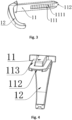
Figure 3 is a schematic structural diagram of the primary connector in the present invention; -
Figure 4 is schematic structural diagram of the primary connector in the present invention; -
Figure 5 is a schematic structural diagram of the secondary connector in the present invention; -
Figure 6 is a schematic structural diagram of the inserting piece in the present invention; -
Figure 7 is a simplified assembly diagram of the primary connector and the plug-in hole in the present invention; -
Figure 8 is a partial enlarged view of Area A inFigure 7 . - In the
figures: 1 is for primary connector; 11-plug-in plate; 111-primary stopping tooth; 1111-first outer surface; 112-plug connector; 113-plug-in flange; 12-first claw structure; 2-secondary connector; 21-connecting end; 211-connecting end body; 2111-Hand-push part; 212-plug-in hole; 2121-first limiting groove; 213-secondary stopping tooth; 2131-second outer surface; 214-inserting piece; 215-slot; 22-second claw structure. - The present invention will now be described in further detail. The embodiments described below are illustrative and are intended to explain the present invention and cannot be interpreted as a restriction to the present invention. Any other embodiments created based on this present invention by any ordinary technician in this industry without any creative work are all covered by the copyright of the present invention.
- In the description of the present invention, it should be understood that the terms "primary (or first)" and "secondary (or second)" are only used to simplify the description, and shall not be interpreted to indicate or imply relative importance, or to implicitly indicate the number of technical features. Thus, features defined as "primary (or first)" and "secondary (or second)" may explicitly or implicitly include one or more of these features. In the description of the present invention, "plurality" means two or more than two, unless otherwise explicitly and specifically restricted.
- In the present invention, unless otherwise expressly stipulated, if Feature 1 is "above" or "below" Feature 2, the two features may or may not be in direct contact. They can be in indirect contact with other feature or features in between. Furthermore, if Feature 1 is "above" or "on" Feature 2, they may or may not be in contact. Feature 1 can be directly above Feature 2 over the latter or is only positioned higher than the latter in altitude. If Feature 1 is "below", "under" or "underneath" Feature 2, former can be directly under the latter, or it is just lower in position than the latter in altitude.
- In order to make the above objects, features and advantages of the present invention more obvious and understandable, specific embodiments of the present invention will be described in detail below with reference to the accompanying drawings.
- In order to solve the problem of poor versatility of the sternal plate in the current versions, the present invention provides an inserted sternum plate, as shown in
Figures 1 to 8 . The said sternum plate includes a primary connector 1 and a secondary connector 2, which are connected to close and secure the incised sternum. Specifically, the primary connector 1 includes a plug-inplate 11 through which it is connected to the secondary connector 2; preferably, the primary connector 1 also includes afirst claw structure 12 connected to the plug-inplate 11; the lower end surface of the plug-inplate 11, that is, the end connected to the secondary connector 2 is provided with a plurality ofprimary stopping teeth 111; the secondary connector 2 includes a connectingend 21, through which it is connected to the primary connector 1; preferably the secondary connector 2 also includes asecond claw structure 22 connected to the connectingend 21; the connectingend 21 includes a connectingend body 211, and a plug-in hole 212 provided on the connectingend body 211; the plug-in hole 212 is adapted to the plug-inplate 11; the bottom surface of the plug-in hole 212 is provided withsecondary stopping teeth 213; the plug-inplate 11 is adapted to the plug-in hole 212, so as to realize the connection of the primary connector 1 and the secondary connector 2 through the engagement of theprimary stopping teeth 111 and thesecondary stopping teeth 213; specifically, during the assembly process, the plug-inplate 11 is inserted into the plug-in hole 212, and opposing thrusts are applied to the primary connector 1 and the secondary connector 2, so that theprimary stopping teeth 111 and thesecondary stopping teeth 213 are engaged, thereby connecting the primary connector 1 and the secondary connector 2. - After the primary connector 1 and the secondary connector 2 are installed at the sternum, when the patient coughs or exerts force on it, the connection between the primary connector 1 and the secondary connector 2 are pulled in the left and right direction, which pulls the primary connector 1 away from the secondary connector 2. Meanwhile, the secondary connector 2 tends to move in the direction away from the primary connector 1, resulting in slippage. To tackle this problem, the present invention preferably ensures that the directions of the arrangement of the
primary teeth 111 and the secondary stoppingteeth 213 are both perpendicular to the direction of the primary connector 1 and the secondary connector 2. With such a design, when the connection between the primary connector 1 and the secondary connector 2 is subject to a force in the left-right direction, both connectors will not move, thanks to the engagement of the primary and secondary stoppingteeth - In order to facilitate the closing and securing of the sternum, the present invention preferably requires that the
first claw structure 12 and thesecond claw structure 22 are both hook-shaped structures suitable for closing and securing the sternum and; after the primary connector 1 and the secondary connector 2 are connected, thefirst claw structure 12 and thesecond claw structure 22 are arranged opposite each other on both sides of the sternum. A space suitable for accommodating the sternum is formed in between so as to realize closing and securing of the sternum. - Furthermore, in the present invention, it is preferred that the number of the primary stopping
teeth 111 is greater than that of the secondary stoppingteeth 213, so that the room accommodating the sternum can be adjusted by selecting the primary stoppingteeth 111 in engagement with the secondary stoppingteeth 213 on the plug-inplate 11 during the installation process. This allows each inserted sternum plate to be adapted to sternums of various sizes, which expands its scope of use and improving its versatility. - In the present invention, the preferred material of the inserted sternal plate is polyetheretherketone (PEEK), or carbon fiber reinforced with PEEK. Such a material is not only capable of ensuring the required mechanical properties of the sternal plate, but also can be cut with scissors off the residual materials after installation. On the other hand, using PEEK or PEEK modified materials, which allows for direct scissors operation, facilitates secondary thoracotomy in certain cases where tissues can grow on the initial implanted sternum plates.
- The inserted sternum plate provided by the present invention realizes the connection between the primary connector and the secondary connector by matching the plug-in
plate 11 with the plug-in hole 212. Since the number of the primary stoppingteeth 111 on the plug-inplate 11 is more than that of the secondary stoppingteeth 213 in the hole 212, the connection length of the plug-in plate can be adjusted as per the size of the sternum, thereby making the inserted sternum plate applicable to sternums of various sizes, helping to expand its range of uses and improving its versatility. - In order to facilitate the connection between the plug-in
plate 11 and the connectingend 21, the present invention prefers that the outer side of the primary stoppingtooth 111, denoted as the firstouter side 1111, is a bevel; specifically, in this article, the outer side of the primary stoppingtooth 111 refers to the side of the primary stoppingteeth 111 away from the first holdingclaw structure 12, after assembling the plug-inplate 11 and the connectingend 21; The structure with the outerouter side 1111 being set as a bevel helps reduce the resistance during the assembly process, thereby reducing the difficulty of assembly. - Similarly, the present invention prefers that the outer side of the secondary stopping
teeth 213, denoted as the firstouter side 2131, is a bevel; specifically, in this article, the outer side of the secondary stoppingtooth 213 refers to the side of the primary stoppingteeth 213 away from the second holdingclaw structure 22, after assembling the plug-inplate 11 and the connectingend 21; The structure with the outerouter side 2131 being set as a bevel helps reduce the resistance during the assembly process, thereby reducing the difficulty of assembly. - To facilitate the assembly, the present invention prefers that the front end of the plug-in
plate 11, that is, the end of the plug-inplate 11 away from thefirst claw structure 12, is provided with a pluggingconnector 112, which can be triangular, arc-shaped, circular, etc. In order to take into account both the convenience of assembly and the aesthetics, theplug connector 112 of the present invention preferably has an arc-shaped structure. - It should be noted that after the primary connector 1 and the primary connector 2 are assembled, the excess portion of one end of the
plug connector 112 on the pluggingplate 11 can be cut, and the specific cutting length is determined according to the size of the sternum. - Furthermore, in the present invention, limiting
flanges 113 are provided on both sides of the plug-inplate 11; a limiting groove matching the limitingflange 113 is provided in the plug-in hole 212, which is marked as the first limitinggroove 2121; In the present invention, it is preferred that the number of the limitingflange 113 and the first limitinggroove 2121 is two; during the assembly process, by inserting the limitingflange 113 into the first limitinggroove 2121 and then pushing them, this helps improve assembly accuracy, making the assembly ease and efficient. - During the assembly process of the inserted sternum plate of the present invention, the plug-in
plate 11 needs to be inserted into the plug-in hole 212. Due to the existence of the primary stoppingteeth 111 and the secondary stoppingteeth 213, it is necessary to exert a great the thrust during the assembly, making it difficult to assemble. To solve this problem, the present invention makes the thickness of the limitingflange 113 smaller than that of the first limitinggroove 2121, that is, the gap between the top of the first limitinggroove 2121 and its bottom is greater than the thickness of theflange 113, so that the limitingflange 113 can be easily inserted into the first limitinggroove 2121 during the assembly process, and then simply engage the primary stoppingteeth 111 with the secondary stoppingteeth 213, which greatly reduces the assembly difficulty. Since the thickness of the limitingflange 113 is smaller than that of the first limitinggroove 2121, after the primary connector 1 and secondary connector 2 are assembled through the engagement of primary stoppingteeth 111 and secondary stoppingteeth 213, there is a clearance between the limitingflange 113 and the top of the first limitinggroove 2121, which form aslot 215, as shown inFigures 7 and 8 . In order to ensure the stability of the sternal plate structure after the assembly is completed, the present invention prefers the connectingend 21 also includes aninsert 214 that is adapted to theslot 215. By inserting theinsert 214 into theslot 215 to fill the gap, the risk of the plug-inplate 11 falling off the plug hole 212 is reduced, and the safety use is further improved. During use, after inserting theinsert piece 214 into theslot 215, the portion of theinsert piece 214 located outside theslot 215 can be cut, if required, and the cutting length can be determined by the actual needs. - In order to facilitate assembly, as shown in
Figure 6 , the present invention preferably incorporates the connecting section of theinsert piece 214, that is, the section of theinsert piece 214 suitable for being inserted into theslot 215 has a tapered structure. Correspondingly, the inner cavity of theslot 215 is also tapered structure. - The connecting section is designed to be a tapered structure. Taper fitting is adopted between the
insert piece 214 and theslot 215. This reduces the difficulty in disassembling theinsert piece 214 from theslot 215, making it easier to disassemble the insert sternum plate. - In order to further improve the stability of the connection, the present invention prefers that the taper of the connecting section is a Morse taper, so that the static fit between the
insert piece 214 and theslot 215 can be achieved through the Morse taper and the principle of friction, thereby achieving the self-locking of theinsert 214, ensuring the stability of the installation without the need for additional components. - Furthermore, in the present invention, the preferred length of the connecting section is 7 mm.
- In order to facilitate the operation, the present invention preferably is provided with hand-
push part 2111 on both sides of theconnection end body 211. The hand-push part 2111 can be set in any structural form suitable for the operator to hold and push hard when needed, so as to facilitate the operator's assembly. During the process, the hand-push part 2111 is used to exert a thrust toward the primary connector 1 on the secondary connector 2, thereby reducing the difficulty in operation. - Taking the above-mentioned ideal embodiments of the present invention as reference and through the above description, relevant workers can make various changes and modifications without deviating from the scope of the technical idea of the present invention. The technical scope of the present invention is not limited to the content in the description and must be determined based on the scope of the claims.
Claims (10)
- An inserted sternum plate, characterized by including a primary connector (1) and a secondary connector (2);the primary connector (1) includes a plug-in plate (11);the lower end surface of the plug-in plate (11) is provided with a number of primary stopping teeth (111);the secondary connector (2) includes a connecting end (21);the connecting end (21) includes a connection end body (211), and a plug hole (212) provided on the connection end body (211);secondary stopping teeth (213) are provided on the bottom surface of the plug-in hole (212);the plug-in plate (11) is adapted to be engaged with the plug-in hole (212), so that the primary stopping teeth (111) and the secondary stopping teeth (213) can be engaged to achieve the connection between the primary connector (1) and the secondary connector (2);the number of the primary stopping teeth (111) is greater than that of the secondary stopping teeth (213);the inserted sternum plate is made of polyetheretherketone or carbon fiber reinforced polyetheretherketone.
- The inserted sternum plate, as described in claim 1, is characterized in that the first outer surface (1111) of the primary stopping teeth (111) is a bevel.
- The inserted sternum plate, as described in claim 1, is characterized in that the first outer surface (2131) of the secondary stopping teeth (213) is a bevel.
- The inserted sternum plate, as described in claim 1, is characterized in that the front end of the plug-in plate (11) is provided with a plug connector (112), which has an arc-shaped structure.
- The plug-in sternum plate, as described in claim 1, is characterized in that limiting flanges (113) are provided on both sides of the plug-in plate (11); In the said plug-in hole (212) the first limiting groove (2121) adapted to the limiting flange (113) are set.
- The inserted sternum plate, as described in claim 5, is characterized in that the thickness of the limiting flange (113) is smaller than the thickness of the first limiting groove (2121), and a slot (215) is formed between the limiting flange (113) and the top surface of the first limiting slot (2121); the connecting end (21) also includes an insert (214) adapted to the slot (215) .
- The inserted sternum plate as described in claim 6, is characterized in that the connecting section of the insert (214) has a tapered structure.
- The inserted sternal plate, as described in claim 7, is characterized by the fact that the taper of its connecting section is measured by Morse taper.
- The inserted sternal plate, as described in claim 7, is characterized by the fact that the length of its connecting section is 7mm.
- The inserted sternum plate, as described in any one of the claims 1 to 9, is characterized in that hand-push insert (214) are provided on both sides of the connecting end's body (2111).
Applications Claiming Priority (1)
| Application Number | Priority Date | Filing Date | Title |
|---|---|---|---|
| CN202311466895.3A CN117281601A (en) | 2023-11-06 | 2023-11-06 | A kind of insert sternum plate |
Publications (3)
| Publication Number | Publication Date |
|---|---|
| EP4548866A1 true EP4548866A1 (en) | 2025-05-07 |
| EP4548866C0 EP4548866C0 (en) | 2026-02-11 |
| EP4548866B1 EP4548866B1 (en) | 2026-02-11 |
Family
ID=89248180
Family Applications (1)
| Application Number | Title | Priority Date | Filing Date |
|---|---|---|---|
| EP24168924.9A Active EP4548866B1 (en) | 2023-11-06 | 2024-04-08 | An inserted sternum plate |
Country Status (6)
| Country | Link |
|---|---|
| EP (1) | EP4548866B1 (en) |
| CN (1) | CN117281601A (en) |
| CA (1) | CA3255019A1 (en) |
| CH (1) | CH721270B1 (en) |
| TW (1) | TWI874162B (en) |
| WO (1) | WO2025098227A1 (en) |
Cited By (1)
| Publication number | Priority date | Publication date | Assignee | Title |
|---|---|---|---|---|
| CN121570234A (en) * | 2026-01-22 | 2026-02-27 | 华融科创生物科技(天津)有限公司 | Sternal fixation device |
Families Citing this family (2)
| Publication number | Priority date | Publication date | Assignee | Title |
|---|---|---|---|---|
| CN117281601A (en) * | 2023-11-06 | 2023-12-26 | 常州华森医疗器械股份有限公司 | A kind of insert sternum plate |
| WO2026130739A1 (en) * | 2024-12-20 | 2026-06-25 | Neos Surgery, S.L. | Closure assembly for securing together parts of a severed bone |
Citations (4)
| Publication number | Priority date | Publication date | Assignee | Title |
|---|---|---|---|---|
| US6051007A (en) * | 1998-03-02 | 2000-04-18 | Corvascular, Inc. | Sternal closure device and instruments therefor |
| CN203970521U (en) * | 2014-07-30 | 2014-12-03 | 曹维 | Claw type sternum fixer |
| WO2017102915A1 (en) * | 2015-12-16 | 2017-06-22 | Neos Surgery, S.L. | Sternal closure assembly |
| WO2019028969A1 (en) * | 2017-08-10 | 2019-02-14 | 常州华森医疗器械有限公司 | Fixator for closing sternum |
Family Cites Families (12)
| Publication number | Priority date | Publication date | Assignee | Title |
|---|---|---|---|---|
| FR2596978A1 (en) * | 1986-04-10 | 1987-10-16 | Peters | BONE FIXING PLATE, PROVIDED WITH SUTURE WIRES |
| US6932820B2 (en) * | 2002-01-08 | 2005-08-23 | Said G. Osman | Uni-directional dynamic spinal fixation device |
| AR037254A1 (en) * | 2002-11-06 | 2004-11-03 | Horacio Abramson | AN APPARATUS FOR CORRECTION OF MALFORMATIONS OF THE TORACICA BOX, SUCH AS "PECTUS EXCAVATUM" AND "PECTUS CARINATUM" AND METHOD FOR CORRECTION OF "PECTUS CARINATUM" |
| US9597132B2 (en) * | 2013-01-12 | 2017-03-21 | Louis Houff | Sternum fixation device and method |
| US10154864B2 (en) * | 2013-02-07 | 2018-12-18 | Louis Houff | Sternum fixation device and method |
| CN207545189U (en) * | 2017-03-11 | 2018-06-29 | 苏州爱得科技发展股份有限公司 | A kind of sternal bar |
| CN106798591B (en) * | 2017-03-11 | 2018-04-13 | 苏州爱得科技发展股份有限公司 | A kind of sternal bar |
| CN110480927B (en) * | 2019-08-14 | 2021-03-26 | 西安康拓医疗技术有限公司 | Molding method of PEEK sternum fixing band |
| CN213910474U (en) * | 2020-10-26 | 2021-08-10 | 张朝兴 | Breastbone fracture plate |
| US11331130B1 (en) * | 2020-12-10 | 2022-05-17 | DePuy Synthes Products, Inc. | Sternal closure systems and methods of use thereof |
| CN114521951B (en) * | 2021-12-31 | 2024-07-05 | 常州华森医疗器械股份有限公司 | Sternum plate convenient to disassemble |
| CN117281601A (en) * | 2023-11-06 | 2023-12-26 | 常州华森医疗器械股份有限公司 | A kind of insert sternum plate |
-
2023
- 2023-11-06 CN CN202311466895.3A patent/CN117281601A/en active Pending
-
2024
- 2024-03-12 TW TW113109051A patent/TWI874162B/en active
- 2024-04-08 EP EP24168924.9A patent/EP4548866B1/en active Active
- 2024-09-12 CA CA3255019A patent/CA3255019A1/en active Pending
- 2024-10-28 CH CH001170/2024A patent/CH721270B1/en unknown
- 2024-10-31 WO PCT/CN2024/128707 patent/WO2025098227A1/en active Pending
Patent Citations (4)
| Publication number | Priority date | Publication date | Assignee | Title |
|---|---|---|---|---|
| US6051007A (en) * | 1998-03-02 | 2000-04-18 | Corvascular, Inc. | Sternal closure device and instruments therefor |
| CN203970521U (en) * | 2014-07-30 | 2014-12-03 | 曹维 | Claw type sternum fixer |
| WO2017102915A1 (en) * | 2015-12-16 | 2017-06-22 | Neos Surgery, S.L. | Sternal closure assembly |
| WO2019028969A1 (en) * | 2017-08-10 | 2019-02-14 | 常州华森医疗器械有限公司 | Fixator for closing sternum |
Cited By (1)
| Publication number | Priority date | Publication date | Assignee | Title |
|---|---|---|---|---|
| CN121570234A (en) * | 2026-01-22 | 2026-02-27 | 华融科创生物科技(天津)有限公司 | Sternal fixation device |
Also Published As
| Publication number | Publication date |
|---|---|
| TWI874162B (en) | 2025-02-21 |
| CA3255019A1 (en) | 2025-11-29 |
| CN117281601A (en) | 2023-12-26 |
| CH721270A2 (en) | 2025-05-15 |
| CH721270B1 (en) | 2026-05-29 |
| WO2025098227A1 (en) | 2025-05-15 |
| TW202519177A (en) | 2025-05-16 |
| EP4548866C0 (en) | 2026-02-11 |
| EP4548866B1 (en) | 2026-02-11 |
Similar Documents
| Publication | Publication Date | Title |
|---|---|---|
| EP4548866B1 (en) | An inserted sternum plate | |
| US20240008904A1 (en) | Systems and Methods for Percutaneous Spinal Fusion | |
| US11759242B2 (en) | Orthopaedic fixation device, system and method | |
| US7488335B2 (en) | Device for ligating an anatomical structure | |
| US8162827B2 (en) | Adjustable polyaxial tissue retractor | |
| CA2579028A1 (en) | Vertebral staples and insertion tools | |
| AU2019342100B2 (en) | Adjustable locking surgical retractor | |
| US20210045756A1 (en) | Minimally invasive displacement osteotomy system and method | |
| CN110123428A (en) | A kind of Quick Release breastbone closing fixer | |
| BRPI0711146A2 (en) | prosthesis, and method for mounting such a prosthesis | |
| US20220133362A1 (en) | Receiving part and instrument for holding the receiving part | |
| KR102715778B1 (en) | Easily disassembled breastbone plate | |
| US20250288336A1 (en) | Sacroiliac joint stabilization systems and methods | |
| RU2837959C1 (en) | Insertion pad on sternum | |
| CN115607340B (en) | Acetabular patch and acetabular patch system | |
| CN220141729U (en) | Separating olecranon | |
| US12446941B2 (en) | Self-retaining screwdriver with slotted tip | |
| CN117281602A (en) | Grid inserted sheet sternum plate | |
| AU2024201354A1 (en) | Anchor Assembly for Fastener |
Legal Events
| Date | Code | Title | Description |
|---|---|---|---|
| PUAI | Public reference made under article 153(3) epc to a published international application that has entered the european phase |
Free format text: ORIGINAL CODE: 0009012 |
|
| STAA | Information on the status of an ep patent application or granted ep patent |
Free format text: STATUS: THE APPLICATION HAS BEEN PUBLISHED |
|
| AK | Designated contracting states |
Kind code of ref document: A1 Designated state(s): AL AT BE BG CH CY CZ DE DK EE ES FI FR GB GR HR HU IE IS IT LI LT LU LV MC ME MK MT NL NO PL PT RO RS SE SI SK SM TR |
|
| STAA | Information on the status of an ep patent application or granted ep patent |
Free format text: STATUS: REQUEST FOR EXAMINATION WAS MADE |
|
| GRAP | Despatch of communication of intention to grant a patent |
Free format text: ORIGINAL CODE: EPIDOSNIGR1 |
|
| STAA | Information on the status of an ep patent application or granted ep patent |
Free format text: STATUS: GRANT OF PATENT IS INTENDED |
|
| 17P | Request for examination filed |
Effective date: 20251030 |
|
| RIC1 | Information provided on ipc code assigned before grant |
Ipc: A61B 17/80 20060101AFI20251121BHEP Ipc: A61B 17/82 20060101ALI20251121BHEP |
|
| GRAS | Grant fee paid |
Free format text: ORIGINAL CODE: EPIDOSNIGR3 |
|
| INTG | Intention to grant announced |
Effective date: 20251209 |
|
| GRAA | (expected) grant |
Free format text: ORIGINAL CODE: 0009210 |
|
| STAA | Information on the status of an ep patent application or granted ep patent |
Free format text: STATUS: THE PATENT HAS BEEN GRANTED |
|
| AK | Designated contracting states |
Kind code of ref document: B1 Designated state(s): AL AT BE BG CH CY CZ DE DK EE ES FI FR GB GR HR HU IE IS IT LI LT LU LV MC ME MK MT NL NO PL PT RO RS SE SI SK SM TR |
|
| REG | Reference to a national code |
Ref country code: CH Ref legal event code: F10 Free format text: ST27 STATUS EVENT CODE: U-0-0-F10-F00 (AS PROVIDED BY THE NATIONAL OFFICE) Effective date: 20260211 Ref country code: GB Ref legal event code: FG4D |
|
| REG | Reference to a national code |
Ref country code: DE Ref legal event code: R096 Ref document number: 602024002458 Country of ref document: DE |
|
| REG | Reference to a national code |
Ref country code: IE Ref legal event code: FG4D |
|
| U01 | Request for unitary effect filed |
Effective date: 20260303 |
|
| U07 | Unitary effect registered |
Designated state(s): AT BE BG DE DK EE FI FR IT LT LU LV MT NL PT RO SE SI Effective date: 20260309 |
|
| U20 | Renewal fee for the european patent with unitary effect paid |
Year of fee payment: 3 Effective date: 20260305 |
|
| PG25 | Lapsed in a contracting state [announced via postgrant information from national office to epo] |
Ref country code: RS Free format text: LAPSE BECAUSE OF FAILURE TO SUBMIT A TRANSLATION OF THE DESCRIPTION OR TO PAY THE FEE WITHIN THE PRESCRIBED TIME-LIMIT Effective date: 20260511 |
|
| PG25 | Lapsed in a contracting state [announced via postgrant information from national office to epo] |
Ref country code: ES Free format text: LAPSE BECAUSE OF FAILURE TO SUBMIT A TRANSLATION OF THE DESCRIPTION OR TO PAY THE FEE WITHIN THE PRESCRIBED TIME-LIMIT Effective date: 20260211 |
|
| PG25 | Lapsed in a contracting state [announced via postgrant information from national office to epo] |
Ref country code: PL Free format text: LAPSE BECAUSE OF FAILURE TO SUBMIT A TRANSLATION OF THE DESCRIPTION OR TO PAY THE FEE WITHIN THE PRESCRIBED TIME-LIMIT Effective date: 20260211 |
|
| PG25 | Lapsed in a contracting state [announced via postgrant information from national office to epo] |
Ref country code: GR Free format text: LAPSE BECAUSE OF FAILURE TO SUBMIT A TRANSLATION OF THE DESCRIPTION OR TO PAY THE FEE WITHIN THE PRESCRIBED TIME-LIMIT Effective date: 20260512 |
|
| PG25 | Lapsed in a contracting state [announced via postgrant information from national office to epo] |
Ref country code: NO Free format text: LAPSE BECAUSE OF FAILURE TO SUBMIT A TRANSLATION OF THE DESCRIPTION OR TO PAY THE FEE WITHIN THE PRESCRIBED TIME-LIMIT Effective date: 20260511 |
|
| PG25 | Lapsed in a contracting state [announced via postgrant information from national office to epo] |
Ref country code: HR Free format text: LAPSE BECAUSE OF FAILURE TO SUBMIT A TRANSLATION OF THE DESCRIPTION OR TO PAY THE FEE WITHIN THE PRESCRIBED TIME-LIMIT Effective date: 20260211 |
|
| PG25 | Lapsed in a contracting state [announced via postgrant information from national office to epo] |
Ref country code: IS Free format text: LAPSE BECAUSE OF FAILURE TO SUBMIT A TRANSLATION OF THE DESCRIPTION OR TO PAY THE FEE WITHIN THE PRESCRIBED TIME-LIMIT Effective date: 20260611 |