EP4548827A1 - Method for activating battery-powered cleaner body by counter-electromotive force, and wireless cleaner device employing same - Google Patents
Method for activating battery-powered cleaner body by counter-electromotive force, and wireless cleaner device employing same Download PDFInfo
- Publication number
- EP4548827A1 EP4548827A1 EP23835664.6A EP23835664A EP4548827A1 EP 4548827 A1 EP4548827 A1 EP 4548827A1 EP 23835664 A EP23835664 A EP 23835664A EP 4548827 A1 EP4548827 A1 EP 4548827A1
- Authority
- EP
- European Patent Office
- Prior art keywords
- cleaner body
- battery
- station
- cleaner
- motor
- Prior art date
- Legal status (The legal status is an assumption and is not a legal conclusion. Google has not performed a legal analysis and makes no representation as to the accuracy of the status listed.)
- Pending
Links
Images











Classifications
-
- A—HUMAN NECESSITIES
- A47—FURNITURE; DOMESTIC ARTICLES OR APPLIANCES; COFFEE MILLS; SPICE MILLS; SUCTION CLEANERS IN GENERAL
- A47L—DOMESTIC WASHING OR CLEANING; SUCTION CLEANERS IN GENERAL
- A47L9/00—Details or accessories of suction cleaners, e.g. mechanical means for controlling the suction or for effecting pulsating action; Storing devices specially adapted to suction cleaners or parts thereof; Carrying-vehicles specially adapted for suction cleaners
- A47L9/10—Filters; Dust separators; Dust removal; Automatic exchange of filters
- A47L9/106—Dust removal
-
- A—HUMAN NECESSITIES
- A47—FURNITURE; DOMESTIC ARTICLES OR APPLIANCES; COFFEE MILLS; SPICE MILLS; SUCTION CLEANERS IN GENERAL
- A47L—DOMESTIC WASHING OR CLEANING; SUCTION CLEANERS IN GENERAL
- A47L9/00—Details or accessories of suction cleaners, e.g. mechanical means for controlling the suction or for effecting pulsating action; Storing devices specially adapted to suction cleaners or parts thereof; Carrying-vehicles specially adapted for suction cleaners
- A47L9/28—Installation of the electric equipment, e.g. adaptation or attachment to the suction cleaner; Controlling suction cleaners by electric means
- A47L9/2868—Arrangements for power supply of vacuum cleaners or the accessories thereof
- A47L9/2884—Details of arrangements of batteries or their installation
-
- A—HUMAN NECESSITIES
- A47—FURNITURE; DOMESTIC ARTICLES OR APPLIANCES; COFFEE MILLS; SPICE MILLS; SUCTION CLEANERS IN GENERAL
- A47L—DOMESTIC WASHING OR CLEANING; SUCTION CLEANERS IN GENERAL
- A47L5/00—Structural features of suction cleaners
- A47L5/12—Structural features of suction cleaners with power-driven air-pumps or air-compressors, e.g. driven by motor vehicle engine vacuum
- A47L5/22—Structural features of suction cleaners with power-driven air-pumps or air-compressors, e.g. driven by motor vehicle engine vacuum with rotary fans
- A47L5/24—Hand-supported suction cleaners
-
- A—HUMAN NECESSITIES
- A47—FURNITURE; DOMESTIC ARTICLES OR APPLIANCES; COFFEE MILLS; SPICE MILLS; SUCTION CLEANERS IN GENERAL
- A47L—DOMESTIC WASHING OR CLEANING; SUCTION CLEANERS IN GENERAL
- A47L9/00—Details or accessories of suction cleaners, e.g. mechanical means for controlling the suction or for effecting pulsating action; Storing devices specially adapted to suction cleaners or parts thereof; Carrying-vehicles specially adapted for suction cleaners
- A47L9/28—Installation of the electric equipment, e.g. adaptation or attachment to the suction cleaner; Controlling suction cleaners by electric means
- A47L9/2836—Installation of the electric equipment, e.g. adaptation or attachment to the suction cleaner; Controlling suction cleaners by electric means characterised by the parts which are controlled
- A47L9/2842—Suction motors or blowers
-
- A—HUMAN NECESSITIES
- A47—FURNITURE; DOMESTIC ARTICLES OR APPLIANCES; COFFEE MILLS; SPICE MILLS; SUCTION CLEANERS IN GENERAL
- A47L—DOMESTIC WASHING OR CLEANING; SUCTION CLEANERS IN GENERAL
- A47L9/00—Details or accessories of suction cleaners, e.g. mechanical means for controlling the suction or for effecting pulsating action; Storing devices specially adapted to suction cleaners or parts thereof; Carrying-vehicles specially adapted for suction cleaners
- A47L9/28—Installation of the electric equipment, e.g. adaptation or attachment to the suction cleaner; Controlling suction cleaners by electric means
- A47L9/2857—User input or output elements for control, e.g. buttons, switches or displays
-
- A—HUMAN NECESSITIES
- A47—FURNITURE; DOMESTIC ARTICLES OR APPLIANCES; COFFEE MILLS; SPICE MILLS; SUCTION CLEANERS IN GENERAL
- A47L—DOMESTIC WASHING OR CLEANING; SUCTION CLEANERS IN GENERAL
- A47L9/00—Details or accessories of suction cleaners, e.g. mechanical means for controlling the suction or for effecting pulsating action; Storing devices specially adapted to suction cleaners or parts thereof; Carrying-vehicles specially adapted for suction cleaners
- A47L9/28—Installation of the electric equipment, e.g. adaptation or attachment to the suction cleaner; Controlling suction cleaners by electric means
- A47L9/2868—Arrangements for power supply of vacuum cleaners or the accessories thereof
- A47L9/2873—Docking units or charging stations
-
- A—HUMAN NECESSITIES
- A47—FURNITURE; DOMESTIC ARTICLES OR APPLIANCES; COFFEE MILLS; SPICE MILLS; SUCTION CLEANERS IN GENERAL
- A47L—DOMESTIC WASHING OR CLEANING; SUCTION CLEANERS IN GENERAL
- A47L9/00—Details or accessories of suction cleaners, e.g. mechanical means for controlling the suction or for effecting pulsating action; Storing devices specially adapted to suction cleaners or parts thereof; Carrying-vehicles specially adapted for suction cleaners
- A47L9/28—Installation of the electric equipment, e.g. adaptation or attachment to the suction cleaner; Controlling suction cleaners by electric means
- A47L9/2894—Details related to signal transmission in suction cleaners
-
- H—ELECTRICITY
- H02—GENERATION; CONVERSION OR DISTRIBUTION OF ELECTRIC POWER
- H02J—ELECTRIC POWER NETWORKS; CIRCUIT ARRANGEMENTS OR SYSTEMS FOR SUPPLYING OR DISTRIBUTING ELECTRIC POWER; SYSTEMS FOR STORING ELECTRIC ENERGY
- H02J9/00—Circuit arrangements for emergency or stand-by power supply, e.g. for emergency lighting
- H02J9/005—Circuit arrangements for emergency or stand-by power supply, e.g. for emergency lighting using a power saving mode
-
- H—ELECTRICITY
- H02—GENERATION; CONVERSION OR DISTRIBUTION OF ELECTRIC POWER
- H02J—ELECTRIC POWER NETWORKS; CIRCUIT ARRANGEMENTS OR SYSTEMS FOR SUPPLYING OR DISTRIBUTING ELECTRIC POWER; SYSTEMS FOR STORING ELECTRIC ENERGY
- H02J7/00—Circuit arrangements for charging or discharging batteries or for supplying loads from batteries
- H02J7/855—Circuit arrangements for charging or discharging batteries or for supplying loads from batteries with circuits adapted for supplying loads from the battery
Definitions
- An embodiment of the disclosure relates to a method of electrically activating one of two devices through back-electro motive force (BEMF) when the two devices including motors are coupled or connected through a flow path, and a device employing the method.
- BEMF back-electro motive force
- a cordless cleaner is a type of vacuum cleaner that charges and uses a battery built in the vacuum cleaner itself without having to connect a wire to an outlet.
- the cordless cleaner includes a suction motor that generates suction power, and may suck up foreign substances such as dust along with air from a vacuum cleaner head (brush) through the suction power generated by the suction motor, separate the sucked up foreign substances from the air, and collect the dust.
- cordless cleaners are very convenient to use because they do not connect power lines. That is why cordless cleaners are becoming popular.
- use of cordless cleaners is becoming increasingly diverse according to users and environmental conditions.
- cordless cleaners for coupling a station (dust discharger) that automatically empties dust from a dust bin attached to a cordless cleaner body when docking with the station have been also used, and the use, methods, and structures of cordless cleaners have become very diverse.
- the cordless cleaner body is cordlessly powered by a battery.
- the cleaner body provides various display functions in addition to a cleaning function, and thus, continuous battery charging is required.
- the battery life decreases, and thus, it is necessary to charge the battery efficiently while performing functions of the cleaner body smoothly.
- a cordless cleaner device includes a cordlessly powered cleaner body including a first motor and a battery configured to supply power to a main processor, a station including a second motor driven based on a second motor driving event, and a station processor configured to control the second motor to be driven according to the second motor driving event, and a flow path shared by the cleaner body and the station, wherein back-electro motive force (BEMF) is generated in the first motor by rotation of a suction fan connected to the first motor according to an air flow of the flow path by the driving of the second motor, the main processor is activated by the BEMF, and the first motor and the second motor each include a suction motor.
- BEMF back-electro motive force
- a method of electrically activating a battery-powered cordless cleaner device includes, by a station processor, detecting a second motor driving event in a station, by the station processor, driving a second motor according to the second motor driving event, rotating a suction fan of a first motor in a cleaner body by a pressure difference generated in a flow path shared between the cleaner body and the station according to the driving of the second motor, waking up a battery processor of the cleaner body by BEMF generated by rotation of the suction fan of the first motor, and by the battery processor, activating a main processor of the cleaner body powered by a battery of the cleaner body.
- the expression "at least one of a, b or c" indicates only a, only b, only c, both a and b, both a and c, both b and c, all of a, b, and c, or variations thereof.
- the method may reduce power consumption of the cordless cleaner 3000 and extend the battery life.
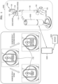
- FIG. 1 is a diagram of a cordless cleaner in which a station and a cleaner body are coupled according to an embodiment of the disclosure.
- the cordless cleaner 3000 in which the station 2000 and the cleaner body 1000 are coupled may be a stick-type vacuum cleaner including the cleaner body 1000, a brush device 120, and an extension tube 130.
- the cordless cleaner 3000 according to an embodiment of the disclosure may be a hand-type vacuum cleaner including the cleaner body 1000 and the brush device 120.
- the cordless cleaner 3000 according to an embodiment of the disclosure may be a wireless vacuum cleaner including the cleaner body 1000, the brush device 120, an extension tube 130, and the station 2000.
- the cordless cleaner 3000 according to an embodiment of the disclosure may be a vacuum cleaner that may be selectively used among a hand type, an automatic movable type, and a stick type.
- the hand-type cleaner, the automatic movable or/and the stick-type cleaner according to an embodiment of the disclosure may be a cordless cleaner.
- the cleaner body 1000 is a part that a user may hold and move when cleaning.
- the cleaner body 1000 may include a dust bin (or dust collector bin) 110 in which foreign substances sucked up from a surface to be cleaned (e.g., a hard floor, a carpet, a mat, etc.), bedding, sofa, etc. are accommodated.
- the cleaner body 1000 may include a filter unit 140 that filters out ultrafine dust that is not filtered out from the dust bin 110, and discharges air from which the ultrafine dust has been removed to the outside of the cleaner body 1000.
- the cleaner body 1000 may include a pressure sensor 160 used to detect a value of pressure inside a dust suction flow path (hereinafter, referred to as dust suction flow path pressure).
- the dust suction flow path of the cleaner body 1000 may represent a period from a position where suction of air including foreign substances starts to a position where air from which foreign substances has been removed is discharged.
- the dust suction flow path of the cleaner body 1000 may represent a period from a suction port 129 of the brush device 120 to the filter unit 140 of the cleaner body 1000, but is not limited thereto.
- the cleaner body 1000 may include a battery 150 that supplies power to the cleaner body 1000.
- the cleaner body 1000 may include a user interface 170 that receives a user input and outputs information about a self-diagnosis result of the cordless cleaner 3000. As shown in FIG. 1 , various pieces of information may be displayed on the user interface 170.
- a processor of the cleaner body 1000 when a processor of the cleaner body 1000 is performing self-diagnosis, "self-diagnosis is in progress" may be displayed on the user interface 170, and when the self-diagnosis result indicates that measures are necessary, for example, "free motor filter/dust bin cleaning" may be displayed on the user interface 170.
- Displaying the information through the user interface 170 by the cleaner body 1000 depends on power supplied from the battery 150, and accordingly, the battery 150 of the cleaner body 1000 needs to be charged by a charging circuit 2010 of the station 2000.
- the information displayed on the cleaner body 1000 is further described with reference to FIG. 2 .
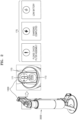
- FIG. 2 is a diagram illustrating displaying information on a cleaner body according to an embodiment of the disclosure.
- the cleaner body 1000 of the cordless cleaner 3000 may include a user interface 170, and the user interface 170 may include an input interface 171 through which a command may be input to the cordless cleaner 3000 and an output interface 173 through which the cordless cleaner 3000 displays information to a user.
- the input interface 171 may be a user input interface capable of touch recognition.
- the output interface 173 may be an LCD or an LED display, but is not limited thereto.
- the output interface 173 may display various information that may show a state of the cordless cleaner 3000 to the user. Referring to FIG. 2 , information such as "Please check the filter assembly", "Charging completed", and "Low Battery” may be displayed on the output interface 173.
- the output interface 173 of the cleaner body 1000 informs the state of the cordless cleaner 3000
- the output interface 173 is convenient for the user to obtain information, but this causes power in the cordless cleaner 3000 to be continuously consumed. Because power in the cordless cleaner 3000 is consumed, the battery 150 is discharged, and accordingly, the station 2000 needs to continuously compensate and charge the battery 150 according to a certain cycle.
- the output interface 173 may provide information such as an operating state or a state of charge of the cordless cleaner 3000, and whether the cordless cleaner 3000 is charged.
- the reason why the battery 150 provided in the cleaner body 1000 does not completely interrupt power of a main circuit including the user interface 170 of the cleaner body 1000 is that there is a connection operation between the cleaner body 1000 and the station 2000. In other words, power needs to be continuously supplied from the station 2000 to the battery 150 of the cleaner body 1000 in order to perform the connection operation between the cleaner body 1000 and the station 2000.
- the station 2000 may mainly perform an automatic/manual dust emptying operation and communication with the cleaner body 1000 via a communication connection (WiFi and BLE). Besides, continuous power consumption occurs in the cleaner body 1000 by performing communication operations between a user terminal 5000 ⁇ the station 2000 ⁇ the cleaner body 1000, and the connection operation between the cleaner body 1000 and the station 2000. Even after charging is completed by mounting or docking the cleaner body 1000 on the station 2000, power consumption continuously occurs in a related circuit including a driver (LCD driver) which is a driving circuit of the output interface 173, a detection sensor, and a communication interface.
- a driver LCD driver
- the power of the battery 150 included in the cleaner body 1000 is continuously supplied to a circuit (e.g., a controller) of the cleaner body 1000, which causes the power of the battery 150 of the cleaner body 1000 to be consumed.
- a circuit e.g., a controller
- the power consumption of the battery 150 leads to frequent battery charging and compensation charging, which affects the life of the battery 150, causing a situation where a replacement time of the battery 150 is inevitably frequent.
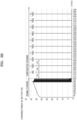
- FIG. 3A is a graph showing battery compensation charging of a cordless cleaner.
- a normal charging cycle occurs in which the battery 150 of the cleaner body 1000 is charged.
- a period in which the battery 150 is charged for about 2 hours and 30 minutes occurs, and a time length of the normal charging cycle may vary according to the capacity or the magnitude of charging power of the battery 150.
- the battery 150 is consumed due to power consumption of related circuits such as a controller circuit of the cleaner body 1000 and the user interface 170.
- the reason why the battery 150 provided in the cleaner body 1000 does not completely interrupt power of a main circuit including the user interface 170 of the cleaner body 1000 is that there is a connection operation between the cleaner body 1000 and the station 2000.
- power needs to be continuously supplied from the station 2000 to the cleaner body 1000, and the battery 150 of the cleaner body 1000 needs to continuously supply power to the cleaner body 1000.
- a compensation charging cycle of the battery 150 is continued even after the normal charging cycle. Referring to FIG. 3A , it may be seen that compensation charging occurs 1 time every about an hour even after the normal charging of the battery 150 due to the continuous power consumption of the cleaner body 1000. This is an example, and a compensation charging cycle may vary depending on setting of a manufacturer.
- the cleaner body 1000 of the cordless cleaner 3000 being 'coupled' to the station 2000 includes any forms of coupling in which the cleaner body 1000 may be electrically connected to the station 2000.
- the cleaner body 1000 of the cordless cleaner 3000 being 'coupled' to the station 2000 includes all forms of coupling in which the cleaner body 1000 is mounted on the station 2000, and the cleaner body 1000 is electrically coupled to the side or the bottom of the station 2000.
- FIG. 3B is a graph showing battery compensation charging of a cordless cleaner.
- FIG. 3B shows a different type of battery compensation charging of the cordless cleaner 3000 from the cordless cleaner 3000 of FIG. 3A .
- the cordless cleaner 3000 of FIG. 3B also performs periodic compensation charging every about an hour due to continuous power consumption in the cleaner body 1000 even after the battery 150 of the cleaner body 1000 is fully charged.
- the cordless cleaner 3000 operates by the battery 150 rather than a power line, battery efficiency-power efficiency are important. Therefore, it is necessary to minimize power loss occurring in the battery 150.
- the efficiency of the battery 150 is low, an operation time of the battery 150 is shortened, and this low efficiency leads to frequent charging and compensation charging of the battery 150, which affects a battery life. The shorter battery life leads to frequent battery replacements.
- the cordless cleaner 3000 is mostly placed for storage rather than for use (cleaning). Therefore, when the power consumption occurred when the cordless cleaner 3000 is not in use (cleaning) may be minimized, overall battery efficiency may be improved, and potential failure factors of parts may be eliminated. Therefore, it is necessary to improve the overall efficiency by minimizing the power consumption occurred under the condition that the cordless cleaner 3000 is not in use (cleaning).
- the cleaner body 1000 may mount a pressure sensor on a part of a suction duct, but is not limited thereto.
- the cleaner body 1000 may include more or fewer components than the components shown in FIG. 1 .
- the specific configuration of the cleaner body 1000 will be described in detail with reference to FIG. 5 to be described below.
- the brush device 120 is a device in close contact with a surface to be cleaned and sucking up air and foreign substances from the surface to be cleaned.
- the brush device 120 may be expressed as a cleaner head.
- the brush device 120 may be rotatably coupled to the extension tube 130.
- the brush device 120 may include a motor, a motor controller 125, and a drum having a rotating brush attached thereto, but is not limited thereto.
- the brush device 120 may further include at least one processor for controlling communication with the cleaner body 1000.
- the brush device 120 may have various types.
- the extension tube 130 may be formed as a pipe or a flexible hose having a certain rigidity. Accordingly, the extension tube 130 may be referred to as a pipe.
- the extension tube 130 may transfer suction power generated through a first suction motor 111 of the cleaner body 1000 to the brush device 120, and move air and foreign substances sucked up through the brush device 120 to the cleaner body 1000.
- the extension tube 130 may have a vacuum state according to an operation of the first suction motor 111.
- the extension tube 130 may be detachably connected to the brush device 120.
- the extension tube 130 may be formed in multiple steps between the cleaner body 1000 and the brush device 120. Two or more extension tubes 130 may be provided.
- the cleaner body 1000, the brush device 120, and the extension tube 130 included in the cordless cleaner 3000 may include power lines for transferring power supplied from the battery 150 to the cleaner body 1000 and the brush device 120.
- the cordless cleaner 3000 may supply power to the cleaner body 1000 and the brush device 120 by using power lines.
- the cleaner body 1000 may detect whether the brush device 120 is attached or detached, identify a type of the brush device 120, and adaptively control an operation (e.g., rotations per minute (RPM) of the rotating brush (or the drum) and an RPM of a motor mounted on the brush device 120) of the brush device 120 according to a usage environment state (e.g., a hard floor, a carpet, a mat, a corner, a state being lifted from the surface to be cleaned or a no-load state).
- a usage environment state e.g., a hard floor, a carpet, a mat, a corner, a state being lifted from the surface to be cleaned or a no-load state.
- the cleaner body 1000 may have a reference value for a pressure value of a dust suction flow path related to a state where the brush device 120 is not affected by the surface to be cleaned.
- the reference value for the pressure value of the dust suction flow path may be stored in the memory 180, and read or obtained by at least one main processor 1011 and used.
- a communication system may include the cordless cleaner 3000, the station 2000, and a server 4000.
- the communication system may be implemented with more or fewer components than those shown in FIG. 1 .
- the communication system may be implemented to include the cleaner body 1000 and the station 2000, except for the server 4000.
- the communication system may be implemented to further include the user terminal 5000.
- the user terminal 5000 may be a terminal registered in the server 4000 under the same account as the cordless cleaner 3000 or the station 2000.
- the user terminal 5000 may include, for example, a movable terminal (e.g., a smartphone, a wearable device, and a tablet), a home appliance including a display (e.g., a refrigerator, a TV, a computer, etc.), etc., but is not limited thereto.
- a movable terminal e.g., a smartphone, a wearable device, and a tablet
- a home appliance including a display (e.g., a refrigerator, a TV, a computer, etc.), etc., but is not limited thereto.
- the cordless cleaner 3000 may refer to a cordless vacuum cleaner that has the rechargeable battery 150 embedded therein and does not need to connect a power cord to an outlet during cleaning, but is not limited thereto.
- the cordless cleaner 3000 may include a robot cleaner that automatically performs cleaning while the cleaner body 1000 automatically moves the surface to be cleaned. The user may use a handle mounted on the cleaner body 1000 to allow the brush device (cleaner head) 120 to suck up dust or foreign substances (garbage) from the surface to be cleaned by moving the cleaner body 1000 back and forth.
- the cordless cleaner 3000 may include a communication interface for performing communication with the station 2000. For example, the cordless cleaner 3000 may transmit and receive data to and from the station 2000 over a wireless personal area network (WPAN).
- WPAN wireless personal area network
- the station 2000 may be a device for discharging dust collected in the cleaner body 1000, and charging or mounting a battery.
- the station 2000 may be expressed as a clean station.
- the station 2000 may communicate with the cleaner body 1000 or the server 4000 over a network.
- the station 2000 may transmit and receive data to and from the cleaner body 1000 over the WPAN that does not use an access point (AP).
- the station 2000 may transmit and receive data to and from the server 4000 through the AP that connects a local area network (LAN) to which the station 2000 is connected to a wide area network (WAN) to which the server 4000 is connected.
- LAN local area network
- WAN wide area network
- the station 2000 may be connected to the cleaner body 1000 through Bluetooth Low Energy (BLE) communication, and may be connected to the server 4000 through Wi-Fi (IEEE 802.11).
- BLE Bluetooth Low Energy
- the station 2000 may serve to relay communication between the cleaner body 1000 and the server 4000 when a Wi-Fi communication module is not provided in the cleaner body 1000. For example, the station 2000 may upload data received from the cleaner body 1000 to the server 4000. In addition, the station 2000 may transmit data received from the server 4000 to the cleaner body 1000.
- the server 4000 may be a device for managing the station 2000 and the cleaner body 1000.
- the server 4000 may be a home appliance management server.
- the server 4000 may manage user account information and information about home appliance connected to a user account.
- the user may access the server 4000 through the user terminal 5000 to create the user account.
- the user account may be identified by an ID and password set by the user.
- the server 4000 may register the station 2000 and the cleaner body 1000 to the user account according to a determined procedure.
- the server 4000 may register the station 2000 and the cleaner body 1000 by connecting identification information (e.g., a serial number or a MAC address) of the station 2000 and identification information of the cleaner body 1000 to the user account.
- the server 4000 may manage a state of the station 2000 or a state of the cleaner body 1000 by periodically receiving state information of the station 2000 or state information of the cleaner body 1000 from the station 2000.
- a new version of software may be registered to a memory of the server 4000.
- the server 4000 may transmit the new version of software to the station 2000 when a download request for the new version of software is received from the station 2000.
- the software may be expressed as firmware.
- the station 2000 may update software pre-installed on the station 2000 by downloading the new version of software.
- the software related to the control of the station 2000 may include an algorithm related to a dust discharge operation (process) (e.g., an algorithm to control the strength of suction power of a second suction motor of the station 2000), an algorithm related to an operation of an output interface (e.g., LCD and a sound output unit), an algorithm for diagnosing the state of the station 2000, etc., but is not limited thereto.
- the station 2000 may update software pre-installed in the cordless cleaner 3000 by transmitting the new version of software to the cordless cleaner 3000.
- the software related to the control of the cleaner body 1000 may include, but is not limited to, an artificial intelligence (AI) model trained to infer the use environment state of the brush device 120, a control algorithm related to an operation mode of the cleaner body 1000 (e.g., an algorithm to control the strength of suction power of the first suction motor 111 of the cleaner body 1000, and an algorithm to control rotations per minute (hereinafter, referred to as drum RPM) of the rotating brush of the brush device 120), an algorithm to diagnose the state (e.g., filter clogging, dust suction flow path clogging, overload of the brush device 120, misassembling, etc.) of the cleaner body 1000, etc.
- AI artificial intelligence
- the cleaner body 1000 may easily update the pre-installed software in over the air (OTA) method by downloading the new version of software registered to the server 4000 through the station 2000 connected to the server 4000.
- OTA refers to a technology that wirelessly updates software (firmware) by using Wi-Fi communication without connecting to a computer.
- OTA may be expressed as an over the network (OTN).
- the convenience of using the cordless cleaner 3000 may be increased by updating a control algorithm or a learning model of the existing cordless cleaner 3000 to the latest version.
- the station 2000 downloads the new version of software related to the control of the cordless cleaner 3000 to the cordless cleaner 3000 such that the software of the cordless cleaner 3000 may be updated.
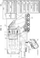
- FIG. 4 is a diagram for explaining a station and a cleaner body according to an embodiment of the disclosure.
- the station 2000 may include a communication interface 201, a memory 202, a pressure sensor 206, and at least one processor 203.
- the station 2000 may further include a user interface 204, a wired connector 205 (e.g., a home appliance smart service (HASS), a second suction motor 207, a power supply device 208, a flow path 209 connected to the dust bin 110 of the cleaner body 1000, a charging terminal 211 for charging the battery 150 of the cleaner body 1000, a dust collector bin coupler, a collector 212, a filter unit, etc.
- the second suction motor 207 is referred to as a second suction motor 207 to be distinguished from the first suction motor 111 of the cleaner body 1000.
- the station 2000 may include the communication interface 201 for performing communication with an external device.
- the station 2000 may communicate with the cleaner body 1000 of the cordless cleaner 3000 or the server 4000 through the communication interface 201.
- the communication interface 201 may communicate with the server 4000 through a first communication method (e.g., Wi-Fi communication method), and communicate with the cleaner body 1000 through a second communication method (e.g., BLE communication method).
- a first communication method e.g., Wi-Fi communication method
- BLE communication method e.g., BLE communication method
- the communication interface 201 may include a short-range wireless communication interface, a long-range wireless communication interface, etc.
- the short-range wireless communication interface may include a Bluetooth communication interface, a Bluetooth Low Energy (BLE) communication interface, a near field communication (NFC) interface, a WLAN (Wi-Fi) communication interface, a Zigbee communication interface, an Infrared Data Association (IrDA) communication interface, a Wi-Fi Direct (WFD) communication interface, an ultra wideband (UWB) communication interface, and an Ant+ communication interface, but is not limited thereto.
- the long-range wireless communication interface may be used for the station 2000 to remotely communicate with the server 4000.
- the long-range wireless communication interface may include the Internet, a computer network (e.g., LAN or WAN), and a movable communication interface.
- the movable communication interface may include, but is not limited to, a 3 rd generation (3G) module, a 4 th generation (4G) module, a 5 th generation (5G) module, a long term evolution (LTE) module, a narrowband Internet of Things (NB-IoT) module, and an LTE-M module.
- 3G 3 rd generation
- 4G 4 th generation
- 5G 5 th generation
- LTE long term evolution
- NB-IoT narrowband Internet of Things
- the communication interface 201 may transmit data to the at least one processor 203 through a universal synchronous receiver/transmitter (UART), but is not limited thereto.
- UART universal synchronous receiver/transmitter
- the memory 202 of the station 2000 may store a program (e.g., one or more commands) for processing and controlling the at least one processor 203, or store input/output data.
- the memory 202 of the station 2000 may include, but is not limited to, software related to control of the station 2000, state data of the second suction motor 207, a measurement value of the pressure sensor 206, error occurrence data (failure history data), information related to charging of the battery 150 - charging interval, recent compensation charging time data, a charging level of the battery 150 during recent compensation charging - etc.
- the memory 202 of the station 2000 may store data received from the cleaner body 1000.
- the memory 202 may store product information (e.g., identification information, model information, etc.) of the cordless cleaner 3000 mounted on the station 2000, version information of software installed in the cordless cleaner 3000, error occurrence data (failure history data) of the cordless cleaner 3000, information related to charging of the battery 150, etc.
- product information e.g., identification information, model information, etc.
- the memory 202 may include at least one type of storage medium among a flash memory type, a hard disk type, a multimedia card micro type, card type memory (e.g., a secure digital (SD) or extreme digital (XD) memory), random access memory (RAM), static random access memory (SRAM), read-only memory (ROM), electrically erasable programmable read-only memory (EEPROM), programmable read-only memory (PROM), magnetic memory, a magnetic disk, or an optical disc.
- Programs stored in the memory 202 may be classified into a plurality of modules according to their functions.
- the station 2000 may include the at least one processor 203.
- the station 2000 may include one processor or a plurality of processors.
- the at least one processor 203 may include at least one a central processing unit (CPU), a graphics processing unit (GPU), an accelerated processing unit (APU), a many integrated core (MIC), a digital signal processor (DSP), or a neural processing unit (NPU).
- the at least one processor 203 may be implemented in the form of an integrated system on chip (SoC) including one or more electronic components.
- SoC system on chip
- Each of the at least one processor 203 may be implemented as separate hardware (H/W).
- the at least one processor 203 may be expressed as a micro-computer, a microprocessor computer, or a microprocessor controller (MICOM), a microprocessor unit (MPU), or a microcontroller unit (MCU).
- MICOM microprocessor controller
- MPU microprocessor unit
- MCU microcontroller unit
- the at least one processor 203 may be implemented as a single core processor or as a multicore processor.
- the at least one processor 203 may control the second suction motor 207 to be driven based on an event of driving the second suction motor 207.
- the event of driving the second suction motor 207 may be at least one of an event in which a user pushes a user input button that is the user interface 204, an event in which a control signal is received through communication from the server 4000 or the user terminal 5000 of the user, an event in which a control signal is executed by the program stored in the memory 202 of the station 2000, or an event in which the cleaner body 1000 is electrically coupled to the station 2000.
- the event of driving the second suction motor 207 may be an event for emptying the dust bin 110 of the cleaner body 1000.
- a control signal for triggering an event by the program stored in the memory 202 of the station 2000 may be periodically executed and generated.
- the cordless cleaner 3000 is a robot cleaner
- the cleaner body 1000 is an automatic movable cleaner body
- the event in which the cleaner body 1000 is electrically coupled to the station 2000 may be an event in which the automatic movable cleaner body completes a certain cleaning operation and is docked on and electrically coupled to the station 2000.
- an event in which the second suction motor 207 of the station 2000 may be driven by an operation in which the automatic movable cleaner body completes a certain cleaning operation and is docked on and electrically coupled to the station 2000 and the station 2000 automatically moves dust collected in the automatic movable cleaner body toward the station 2000.
- the second suction motor 207 when the second suction motor 207 is driven according to the event of driving the second suction motor 207 to empty the dust bin 110 of the cleaner body 1000, dust collected in the dust bin 110 may move to the collector 212 of the station 2000 through the flow path 209 shared by the cleaner body 1000 and the station 2000.
- Back-electro motive force BEMF
- BEMF Back-electro motive force
- the controller 1100 of the cleaner body 1000 may be activated by the generated BEMF.
- the BEMF generated in the first suction motor 111 may be a wake-up signal for activating the controller 1100 of the cleaner body 1000.
- the mechanism by which the BEMF may be generated in the first suction motor 111 included in the cleaner body 1000 according to an air flow of the flow path 209 by driving the second suction motor 207 of the station 2000 is that a pressure difference occurs in the flow path 209 connecting between the cleaner body 1000 and the station 2000 by driving the second suction motor 207 of the station 2000, and the BEMF may be generated in the rotation of a suction fan of the first suction motor 111 by the pressure difference.
- the generated BEMF may serve as a signal for activating the controller 1100 of the cleaner body 1000.
- the user interface 204 of the station 2000 may include an input interface and an output interface.
- the input interface may include a dust discharge button, a mode selection button, etc., which may be input by the user.
- the output interface may include an LED, an LCD, a touch screen, etc., but is not limited thereto.
- the output interface may display a state of charge of the battery 150 of the cleaner body 1000, software update progress information, etc., but is not limited thereto.
- the station 2000 may include the wired connector 205 (e.g., HASS).
- the wired connector 205 may include a terminal for connecting a computing device of a system manager (e.g., a service engineer).
- the pressure sensor 206 of the station 2000 may be a sensor for measuring the pressure of the flow path 209 connecting between the station 2000 and the cleaner body 1000.
- the pressure sensor 206 may measure a pressure value before dust discharging or may measure a pressure value after dust discharging.
- the pressure sensor 206 may transmit the measured pressure value to the at least one processor 203 through inter integrated circuit (I2C) communication, but is not limited thereto, and may transmit the measured pressure value through other types of communication.
- I2C inter integrated circuit
- the second suction motor 207 of the station 2000 may be a device that generates suction power for discharging foreign substances collected in the dust bin 110 of the cleaner body 1000 from the cleaner body 1000.
- the second suction motor 207 may rotate the suction fan for moving air.
- the suction fan may include an impeller.
- the power supply device 208 may include a switching mode power supply (SMPS) that receives alternating current (AC) power from a power source and converts the AC power into direct current (DC) power.
- SMPS switching mode power supply
- AC alternating current
- DC direct current
- the charging terminal 211 is connected to a charging terminal 151 of the cleaner body 1000 and used to charge the battery 150 included in the cleaner body 1000.
- the charging terminal 211 may be connected to the SMPS of the power supply device 208 to provide an electrical connection for charging the battery 150 with the DC power output from the SMPS.
- the dust collector bin coupler may be provided such that the dust bin 110 of the cleaner body 1000 is coupled to the station 2000.
- the dust collector bin coupler may include a docking detection sensor for detecting docking of the cleaner body 1000.
- the docking detection sensor may be a tunnel magneto-resistance (TMR) sensor, but is not limited thereto.
- TMR tunnel magneto-resistance
- the station 2000 may include a step motor that presses one side of a dust bin door 114 to open the dustbin door 114 when the dust bin 110 is docked on the station 2000.
- the collector 212 is a space in which foreign substances discharged from the dust bin 110 of the cleaner body 1000 may be collected.
- the collector 212 may include a dust bag in which foreign substances discharged from the dust bin 110 are collected.
- the dust bag includes a material through which air is transmitted and foreign substances are not transmitted so that foreign substances introduced from the dust bin 110 to the collector 212 may be collected.
- the dust bag may be provided detachably from the collector 212.
- the station 2000 may include an ultraviolet irradiator irradiating ultraviolet rays to the collector 212.
- the ultraviolet irradiator may include a plurality of ultraviolet ramps.
- the filter unit 140 may filter out ultrafine dust which are not collected by the collector 212.
- the filter unit 140 may include a discharge port through which air having passed through the filter is discharged to the outside of the station 2000.
- the filter unit 140 may include a motor filter, a HEPA filter, etc., but is not limited thereto.
- the cordless cleaner 3000 according to an embodiment of the disclosure may be a stick-type cleaner including the cleaner body 1000, the brush device 120, and the extension tube 130.
- the cordless cleaner 3000 according to an embodiment of the disclosure is not limited to the stick-type cleaner, and the cleaner body 1000 may be an automatic movable cleaner such as a robot cleaner.
- the cordless cleaner 3000 may be implemented by more or less components than those shown in FIG. 4 .
- the cordless cleaner 3000 may be implemented as the cleaner body 1000 and the brush device 120, except for the extension tube 130.
- the cleaner body 1000 is a part that a user may hold and move when cleaning, and the cleaner body 1000 may include the first suction motor 111 that forms vacuum inside the cordless cleaner 3000.
- the first suction motor 111 may be located in the dust bin 110 in which foreign substances sucked up from a surface to be cleaned (e.g., floor, bedding, sofa, etc.) are accommodated.
- the cleaner body 1000 may further include the at least one main processor 1011, the battery 150, and the memory 180 in which software related to control of the cordless cleaner 3000 is stored, but is not limited thereto.
- the cleaner body 1000 will be described in more detail below with reference to FIG. 5 .
- the cleaner body 1000 may be a body of an automatic movable cleaner that is not limited to the part that the user may hold and move and automatically moves like a robot cleaner.
- the cleaner body 1000 may have a space detection sensor that detects a space and a wheel for automatically moving attached to the cleaner body 1000.
- the brush device 120 is a device in close contact with the surface to be cleaned and sucking up air and foreign substances from the surface to be cleaned.
- the brush device 120 may be expressed as a cleaner head.
- the brush device 120 may be rotatably coupled to the extension tube 130.
- the brush device 120 may include a motor and a drum having a rotating brush attached thereto, but is not limited thereto.
- the brush device 120 may further include at least one processor for controlling communication with the cleaner body 1000.
- the brush device 120 may have various types.
- the extension tube 130 may be formed as a pipe or a flexible hose having a certain rigidity.
- the extension tube 130 may transfer suction power generated through the first suction motor 111 of the cleaner body 1000 to the brush device 120, and move air and foreign substances sucked up through the brush device 120 to the cleaner body 1000.
- the extension tube 130 may be detachably connected to the brush device 120.
- the extension tube 130 may be formed in multiple steps between the cleaner body 1000 and the brush device 120. Two or more extension tubes 130 may be provided.
- each of the cleaner body 1000, the brush device 120, and the extension tube 130 included in the cordless cleaner 3000 may include a power line (e.g., a + power line and a - power line) and a signal line.
- a power line e.g., a + power line and a - power line
- the power line may be a line for transmitting power supplied from the battery 150 to the cleaner body 1000 and the brush device 120 connected to the cleaner body 1000.
- the signal line is different from the power line, and may be a line for transmitting and receiving signals between the cleaner body 1000 and the brush device 120.
- the signal line may be implemented to be connected to the power line within the brush device 120.
- each of the at least one main processor 1011 of the cleaner body 1000 and the processor of the brush device 120 may perform bidirectional communication between the cleaner body 1000 and the brush device 120 by controlling an operation of a switch device connected to the signal line.
- a switch device connected to the signal line.
- communication between the cleaner body 1000 and the brush device 120 may be defined as 'signal line communication'.
- the cleaner body 1000 and the brush device 120 may communicate with each other by using I2C or UART.
- the cleaner body 1000 may not only detect whether the brush device 2000 is attached or detached, but also identify a type of the brush device 2000 and adaptively control an operation (e.g., drum RPM) of the brush device 2000 according to a usage environment state (e.g., a hard floor, a carpet, a mat, a corner, a state of being lifted from the surface to be cleaned, etc.) of the brush device 2000.
- a usage environment state e.g., a hard floor, a carpet, a mat, a corner, a state of being lifted from the surface to be cleaned, etc.
- the cleaner body 1000 may transmit a signal for controlling the operation of the brush device 120 to the brush device 120, by periodically communicating with the brush device 120.
- the configuration of the cleaner body 1000 will be described in more detail with reference to FIG. 5 .
- FIG. 5 is a diagram for explaining a cleaner body according to an embodiment of the disclosure.
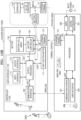
- the cleaner body 1000 may include a suction power generating device (hereinafter referred to as a motor assembly 100), the dust bin 110 (also referred to as a dust collector bin) in which foreign substances sucked up from a surface to be cleaned are accommodated, the filter unit 140, the battery 150 that may supply power to the motor assembly 100, the charging terminal 151 connected to the charging terminal 211 of the station 2000 to charge the battery 150 from the station 2000, the pressure sensor 160, the user interface 170, the memory 180, the communication interface 190, the controller 1100 responsible for overall control of the cleaner body 1000, and at least one main processor 1011.
- a suction power generating device hereinafter referred to as a motor assembly 100
- the dust bin 110 also referred to as a dust collector bin
- the filter unit 140 that may supply power to the motor assembly 100
- the charging terminal 151 connected to the charging terminal 211 of the station 2000 to charge the battery 150 from the station 2000
- the pressure sensor 160 the user interface 170
- the memory 180 the communication interface 190
- the cleaner body 1000 may be implemented by more or fewer components than those shown in FIG. 5 .
- the at least one main processor 1011 included in the controller 1100 and a first processor 1131 of a printed circuit board (PCB) 113 described below are described separately for convenience of explanation, but both may be implemented as a single processor and divided into a plurality of processors and mounted on the cordless cleaner 3000.
- PCB printed circuit board
- the motor assembly 100 may include the first suction motor 111 converting electric force into mechanical rotational force, a fan 112 rotatably connected to the first suction motor 111, and the PCB 113 connected to the first suction motor 111.
- the first suction motor 111 may form vacuum inside the cordless cleaner 3000.
- the vacuum means a state lower than atmospheric pressure.
- the first suction motor 111 may include a brushless direct current (BLDC) motor, but is not limited thereto.
- BLDC brushless direct current
- the PCB 113 may include, but is not limited to, a processor (hereinafter referred to as a first processor 1131) that controls the first suction motor 111 and controls communication with the brush device 120, a switch 1210 (e.g.: a field effect transistor (FET), a transistor, an insulated gate bipolar transistor (IGBT), etc.) of an inverter 1200 for controlling power supply to the brush device 120 by pulse width modulation (PWM) switching, a load detection sensor 1134 (e.g., shunt resistor, shunt resistor and amplification circuit (operational amplifier (OP-AMP)), a current detection sensor, and a magnetic field detection sensor (a contactless method, etc.).
- a processor hereinafter referred to as a first processor 1131
- a switch 1210 e.g.: a field effect transistor (FET), a transistor, an insulated gate bipolar transistor (IGBT), etc.
- PWM pulse width modulation
- a load detection sensor 1134 e.
- the PCB 113 may include a charge release switch 1217 for releasing charging between the station 2000 and the cleaner body 1000, the switch 1210 of the inverter 1200, and the load detection sensor 1134.
- the charge release switch 1217, the switch 1210 and the load detection sensor 1134 may be included in a sub-PCB 1132 separated from the PCB 113 and the sub-PCB 1132 may be located in a battery pack including the battery 150 or may be included in a battery controller 155 which will be described below with reference to FIG. 12A .
- the battery controller 155 may include a battery processor 1551.
- the first processor 1131 may obtain data (hereinafter, referred to as state data) related to a state of the first suction motor 111 and transmit the state data of the first suction motor 111 to the main processor 1011.
- state data data related to a state of the first suction motor 111
- the battery processor 1551 included in the battery controller 155 may release charging of the battery 150 by controlling (e.g., turning on or off) an operation of the charge release switch 1217.
- the first processor 1311 may transmit data indicating a current state of the brush device 120 included in a second signal or data indicating the type of the brush device 120 to the main processor 1011.
- the motor assembly 100 may be located in the dust bin 110.
- the dust bin 110 may be configured such that dust or dirt is filtered out from air introduced through the brush device 120 and collected.
- the dust bin 110 may be provided detachably from the cleaner body 1000.
- the dust bin 110 may collect foreign substances through a cyclone method of separating foreign substances by using centrifugal force. Air from which foreign substances are removed through the cyclone method may be discharged to the outside of the cleaner body 1000, and the foreign substances may be stored in the dust bin 110.
- a multi-cyclone may be disposed inside the dust bin 110.
- the dust bin 110 may be provided such that foreign substances are collected at a lower side of the multi-cyclone.
- the dust bin 110 may include the dust bin door 114 provided to open the dust bin 110 when connected to the station 2000.
- the dust bin 110 may include a first dust collector in which relatively large foreign substances are firstly collected and a second dust collector in which relatively small foreign substances are secondly collected by the multi-cyclone. Both the first dust collector and the second dust collector may be provided to be opened to the outside when the dust bin door 114 is opened.
- the filter unit 140 may filter out ultrafine dust that is not filtered out from the dust bin 110.
- the filter unit 140 may include a discharge port through which air having passed through a filter is discharged to the outside of the cordless cleaner 3000.
- the filter unit 140 may include a motor filter, a HEPA filter, etc., but is not limited thereto.
- the pressure sensor 160 may measure pressure inside the dust suction flow path (hereinafter, also referred to as dust suction flow path pressure).
- the pressure sensor 160 provided at a suction end (e.g., a suction duct 40) may measure static pressure to measure a change in a flow speed at the corresponding location.
- the pressure sensor 160 may be an absolute pressure sensor or a relative pressure sensor. When the pressure sensor 160 is an absolute pressure sensor, the main processor 1011 may sense a first pressure value before operating the first suction motor 111 by using the pressure sensor 160.
- the dust suction flow path pressure measured by the pressure sensor 160 may be used to identify a current usage environment state of the brush device 120 (e.g., a state of a surface to be cleaned (a hard floor, a carpet, a mat, a corner, etc.), a state of being lifted from the surface to be cleaned, etc.), or may be used to measure suction power that changes according to a degree of contamination or dust collection of the bin 110.
- a current usage environment state of the brush device 120 e.g., a state of a surface to be cleaned (a hard floor, a carpet, a mat, a corner, etc.), a state of being lifted from the surface to be cleaned, etc.
- suction power that changes according to a degree of contamination or dust collection of the bin 110.
- the pressure sensor 160 may be located at the suction end (e.g., the suction duct 40).
- the suction duct 40 may be a structure that connects the dust bin 110 to the extension tube 130, or the dust bin 110 to the brush device 120 so that a fluid including foreign substances may move to the dust bin 110.
- the pressure sensor 160 may be located at the end of a straight portion (or an inflection point of the straight portion and a curved portion) of the suction duct 40 in consideration of contamination of foreign substances/dust, but is not limited thereto.
- the pressure sensor 160 may be located in the middle of the straight portion of the suction duct 40.
- the pressure sensor 160 may be implemented as a negative pressure sensor.
- the pressure sensor 160 may be located at a discharge end (e.g., in the motor assembly 100).
- the pressure sensor 160 may be implemented as a positive pressure sensor.
- a plurality of pressure sensors 160 may be provided in the cordless cleaner 3000.
- the battery 150 may be detachably mounted on the cleaner body 1000.
- the battery 150 may be charged by the station 2000 by electrically connecting the charging terminal 211 provided in the station 2000 to the charging terminal 151 of the cleaner body 1000.
- the cleaner body 1000 may include the communication interface 190 for performing communication with an external device.
- the cleaner body 1000 may communicate with the station 2000 (or the server 4000) through the communication interface 190.
- the communication interface 190 may include a short-range wireless communication interface, a long-range wireless communication interface, etc.
- the short-range wireless communication interface may include a Bluetooth communication interface, a BLE communication interface, an NFC interface, a WLAN (Wi-Fi) communication interface, a Zigbee communication interface, an IrDA communication interface, a WFD communication interface, an UWB communication interface, and an Ant+ communication interface, but is not limited thereto.
- the user interface 170 may be provided on a part of a handle of the cleaner body 1000.
- the user interface 170 may include the input interface 171 and the output interface 173.
- the cleaner body 1000 may receive a user input related to the operation of the cordless cleaner 3000 through the user interface 170, and may output information related to the operation of the cordless cleaner 3000.
- the input interface 171 may include a power button, a suction power level control button, etc.
- the output interface 173 may include an LED display, an LCD, a touch screen, etc., but is not limited thereto.
- the cleaner body 1000 may include the at least one main processor 1011.
- the cleaner body 1000 may include one processor or a plurality of processors.
- the cleaner body 1000 may include the at least one main processor 1011 connected to the user interface 170 and the first processor 1131 connected to the first suction motor 111.
- the at least one main processor 1011 may control overall operations of the cleaner body 1000 or the cordless cleaner 3000.
- the main processor 1011 may determine power consumption (strength of suction power) of the first suction motor 111, a drum RPM of the brush device 120, a trip level of the brush device 120, etc.
- the at least one processor 1011 may include at least one of a CPU, a GPU, an APU, a MIC, a DSP, or a NPU.
- the at least one processor 1001 may be implemented in the form of an integrated SoC including one or more electronic components.
- the at least one processor 1011 may be expressed as a MICOM, a MPU, or a MCU.
- the at least one processor 1011 may be implemented as a single core processor or as a multicore processor.
- the memory 180 may store programs for processing and control of the at least one processor 1011 or may store input/output data.
- the memory 180 may store a pre-trained Al model (e.g., a support vector machine (SVM) algorithm, etc.), state data of the first suction motor 111, a measurement value of the pressure sensor 160, state data of the battery 150, a compensation charging cycle of the battery 150, the most recent compensation charging time data of the battery 150, state data of the brush device 120, error occurrence data (failure history data), power consumption of the first suction motor 111 corresponding to operating conditions, a RPM of a drum to which a rotating brush is attached, the trip level, etc.
- the trip level is for preventing overload of the brush device 120 and may mean a reference load value (e.g., a reference current value) for stopping the operation of the brush device 120.
- the memory 180 may include an external memory 181 and an internal memory 183.
- the memory 180 may include at least one type of storage medium among a flash memory type, a hard disk type, a multimedia card micro type, card type memory (e.g., a SD or XD memory), RAM, SRAM, ROM, EEPROM, PROM, magnetic memory, a magnetic disk, or an optical disc.
- Programs stored in the memory 180 may be classified into a plurality of modules according to their functions.
- FIG. 6 is a diagram illustrating a communication connection structure between internal components of a cleaner body according to an embodiment of the disclosure.
- a communication connection structure between components inside the cleaner body 1000 of the cordless cleaner 3000 according to an embodiment of the disclosure is illustrated.
- the controller 1100 sucks up dust by receiving power from the battery 150 and controlling the first suction motor 111.
- the pressure sensor 160 senses pressure of a flow path through which the dust sucked up by the brush device 120 passes while moving to the dust bin 110.
- the controller 1100 may include the at least one main processor 1011.
- the at least one main processor 1011 may perform UART communication with the communication interface 190, and the communication interface 190 may communicate with an external device or the outside of the controller 1100.
- the communication interface 190 may perform BLE communication with an external device or the outside of the controller 1100.
- the at least one main processor 1011 may also receive a pressure sensing value of a dust suction flow path from the pressure sensor 160 through I2C communication.
- the at least one main processor 1011 may perform UART communication with the first processor 1131 of the PCB 113.
- the first processor 1131 may control the first suction motor 111 of the cleaner body 1000, obtain data (hereinafter, referred to as state data) related to a state of the first suction motor 111, and transmit the state data of the first suction motor 111 to the main processor 1011 through UART communication.
- the first processor 1131 may communicate with the brush device 120 through asynchronous communication.
- a battery pack including the battery 150 may include the battery controller 155 capable of checking a charge state of the battery 150 and waking up the battery 150 as well as battery cell related control.
- the at least one main processor 1011 may transmit and receive data to and from the battery controller 155 of the battery 150 through UART communication.
- the battery controller 155 may include the battery processor 1551. A detailed configuration of the battery controller 155 will be described below with reference to FIG. 12A .
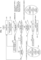
- FIG. 7 is a flowchart illustrating an operation of a cordless cleaner according to an embodiment of the disclosure.
- the cordless cleaner 3000 in a standby mode state.
- the cordless cleaner 3000 is powered-on in the standby mode state or initialized by a charge mounting state in operation S703.
- the cordless cleaner 3000 checks whether there is an abnormality in a product through self-diagnosis.
- the cordless cleaner 3000 may determine whether there is an abnormality in the cordless cleaner 3000 through communication with the server 4000 or the user terminal 5000.
- the cordless cleaner 3000 may detect an abnormality in the battery 150, an abnormality in the first suction motor 111 or the second suction motor 207, or an abnormality in the pressure sensor 160.
- the at least one main processor 1011 of the cordless cleaner 3000 may display whether there is the abnormality through the user interface 170, inform a user of items to be checked, and return to an initial standby mode state.
- the cordless cleaner 3000 is normal, in operation S709, it may be determined through a detection sensor whether the station 2000 and the cleaner body 1000 have been docked.
- the 'docking' includes not only electrical coupling of the station 2000 and the cleaner body 1000, but also mechanical adhesion thereof.
- the "docking" of the station 2000 and the cleaner body 1000 means that the cleaner body 1000 is mounted on the station 2000, but is not limited thereto, and the station 2000 on the top may be mounted on or coupled to the cleaner body 1000 on the bottom, and the station 2000 and the cleaner body 1000 may be docked to each other from the side.
- the detection sensor may be in the station 2000 and/or the cleaner body 1000.
- the at least one main processor 1011 of the cleaner body 1000 determines whether the brush device 120 is mounted on the cleaner body 1000, and when the brush device 120 is not mounted, the cleaner body 1000 operates in a cleaner body (handy) operation mode in operation S717.
- the cleaner body 1000 is a robot cleaner in which the brush device 120 is mounted by default, operation S715 may be omitted.
- the cleaner body (handy) operation mode is not necessarily limited, but is divided into jet mode - super strong mode - strong mode - normal mode in the order of strong suction power.
- the cleaner body (handy) operation mode in which the brush device 120 is not mounted has a stronger suction power than a brush operation mode in which the brush device 120 is mounted. This is because the brush device 120 is mounted, and when the suction power is high, the brush device 120 may stick to the floor.
- the at least one main processor 1011 of the cleaner body 1000 determines whether the mounted brush device 120 is a brush or a wet mop in operation S719.
- the cleaner body 1000 operates in a wet mop mode in operation S721.
- the wet mop mode is a mode in which an end of the cleaner body 1000 sprays water together to facilitate mopping when cleaning.
- a cleaning operation is performed in operation S723, where the brush cleaning operation mode may be divided into jet mode - super strong mode - strong mode - normal mode in the order of strong suction power, just like the handy operation mode.
- the brush cleaning operation mode may be divided into jet mode - super strong mode - strong mode - normal mode in the order of strong suction power, just like the handy operation mode.
- this is merely an example, more diverse modes in the order of strong suction power, or more simplified modes may be provided.
- FIG. 8 is a schematic diagram illustrating generating BEMF in another motor by driving one motor according to an embodiment of the disclosure.
- a first device 810 on the top and a second device 820 on the bottom may or may not be electrically coupled to each other.
- an electric device 800 may be charged in any one device.
- the first device 810 and the second device 820 may be electrically coupled to each other by a charging terminal.
- the first device 810 and the second device 820 may not be electrically connected to each other by the charging terminal but may be mechanically coupled to each other by simply mounting. In this case, when the first device 810 includes a battery, the battery may be charged by another path rather than through the second device 820.
- the first device 810 is on the top and the second device 820 is on the bottom for convenience of explanation, a structure in which the first device 810 is at the bottom and the second device 820 is at the top, a structure in which the first device 810 and the second device 820 are coupled to each other from the side, or a structure in which the first device 810 and the second device 820 are coupled to each other in different directions is also possible.
- any method of generating BEMF to another suction motor according to an operation of one suction motor in any coupling structure may be applied.
- the two suction motors do not necessarily have to be suction motors, and the use of the suction motor may vary depending on the use of the electric device 800.
- first device 810 being 'coupled' to the second device 820 includes any forms of coupling in which the first device 810 may be electrically or mechanically connected to the second device 820.
- first device 810 being 'coupled' to the second device 820 includes all forms of coupling in which the first device 810 is mounted on the second device 820, and the first device 810 is electrically coupled to the side or the bottom of the second device 820.
- the first device 810 being 'coupled' to the second device 820 means that the first device 810 may be electrically or mechanically connected to the second device 820, and thus, it should be considered as the first device 810 being 'coupled' to the second device 820 even when the first device 810 and the second devices 820 are in an electrical interruption state.
- the first device 810 and the second device 820 are 'electrically interrupted' while being electrically connected to each other through a charging terminal, this is only a temporary electrical cutoff state and it should be understood that the first device 810 and the second device 820 may be electrically connected to each other by a specific event.
- the second device 820 may be a device that generally receives power by wired, but is not limited thereto, and the second device 820 may also be a device that is powered by a battery.
- power supplied from a battery of the first device 810 to a controller of the first device 810 is interrupted while the second device 820 and the first device 810 are coupled to each other.
- an electrical connection between the second device 820 and the first device 810 may also be interrupted. At this time, an electrical interruption may be made by the first device 810 or the second device 820.
- the electrical interruption between the second device 820 and the first device 810 may be made by a second controller 825 of the second device 820.
- An event of driving a second motor 821 may occur while the electrical connection between the second device 820 and the first device 810 is interrupted.
- the event of driving the second motor 821 may be at least one of an event of pushing a user input button on the second device 820, an event of receiving a control signal through communication from the server 4000, a user's computing device or the user terminal 5000, an event of executing a control signal by a program stored in a memory of the second device 820, or an event in which the first device 810 is electrically coupled to the second device 820.
- the second motor 821 When the second motor 821 is driven through the event of driving the second motor 821, a pressure difference occurs as air flows in the flow path 850 shared by the first device 810 and the second device 820 by the driving of the second motor 821, and BEMF is generated as a suction fan of the first motor 811 rotates by the pressure difference.
- the generated BEMF may be used as a signal for waking up the first device 810 while electrical insulation is established between the first device 810 and the second device 820, and between a controller and a battery of the first device 810.
- the generated BEMF may be used to activate the battery of the first device 810 and the controller (not shown) of the first device 810.
- the battery of the first device 810 and the controller (not shown) of the first device 810 may be sequentially activated, but the disclosure is not limited thereto.
- the first device 810 may be the cleaner body 1000
- the second device 820 may be the station 2000
- the first motor 811 may be the first suction motor 111 of the cleaner body 1000
- the second motor 821 may be the second suction motor 207 of the station 2000.
- the controller of the first device 810 may be the controller 1100 of the cleaner body 1000
- the second controller 825 may be a main printed board assembly (PBA) 200 of the station 2000.
- the first device 810 may be an automatic movable cleaner (robot cleaner) body
- the second device 820 may be a station of the robot cleaner
- the electric device 800 may be the automatic movable cleaner (robot cleaner).
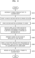
- FIG. 9 is a flowchart illustrating an operation of supplying power to a device operating cordlessly according to BEMF generated in another motor by driving one motor according to an embodiment of the disclosure.
- the first device 810 may be the cleaner body 1000
- the second device 820 may be the station 2000
- the first motor 811 may be the first suction motor 111 of the cleaner body 1000
- the second motor 821 may be the second suction motor 207 of the station 2000.
- a controller of the first device 810 may be the controller 1100 of the cleaner body 1000, especially the main processor 1011
- the second controller 825 may be the processor 203 of the station 2000.
- the first device 810 may be an automatic movable cleaner (robot cleaner) body
- the second device 820 may be a station of the robot cleaner
- the electric device 800 may be the automatic movable cleaner (robot cleaner).
- operation S910 first, power is interrupted from a battery included in the first device 810 to the controller of the first device 810 to prevent power consumption of the controller of the first device 810. Also, selectively, a connection between the battery of the first device 810 and the first motor 811 may be interrupted. At this time, the first device 810 may be the cleaner body 1000.
- the first device 810 and the second device 820 that may be electrically or mechanically coupled to each other include the first motor 811 and the second motor 821, respectively, and an event in which the second motor 821 is driven occurs in operation S920.
- the processor 203 of the station 2000 as the second device 820 receives and detects such an event.
- the event in which the second motor 821 is driven may occur in various ways.
- the event of driving the second motor 821 may occur while an electrical connection between the first device 810 and the second device 820 is interrupted.
- the event of driving the second motor 821 may be at least one of an event of pushing a user input button on the second device 820, an event of receiving a control signal through communication from the server 4000 or the user terminal 5000, or an event of executing a control signal by a program stored in a memory of the second device 820.
- the event of pushing the user input button on the second device 820 may be an event for emptying the dust bin 110 of the cleaner body 1000 in the case of the cordless cleaner 3000.
- the event according to the control signal received through communication from the server 4000 or the user terminal 5000 or the event according to the control signal received by the program stored in the memory of the second device 820 may be an event related to emptying the dust bin 110 of the cleaner body 1000 or charging the battery of the first device 810.
- the second motor 821 is driven according to the event in which the second motor 821 is driven.
- the driving of the second motor 821 may be an operation for sucking up dust from the dust bin 110 of the cleaner body 1000 to the collector 212 of the station 2000 when the electric device 800 is the cordless cleaner 3000.
- a suction fan of the first motor 811 in the first device 810 rotates by a pressure difference occurred in the flow path 850 shared by the first device 810 and the second device 820 according to the driving of the second motor 821.
- BEMF is generated by rotation of the suction fan of the first motor 811. The generated BEMF is transmitted to the inside of the first device 810 as a kind of wake-up signal.
- the BEMF may be used to activate the battery processor 1551 responsible for controlling the battery of the first device 810, and the battery processor may activate the main processor 1011 of the cleaner body 1000.
- the BEMF may be used to directly activate the main processor 1011 of the cleaner body 1000, which is the first device 810.
- the BEMF transmitted to the first device 810 as the wake-up signal may be used as a signal for activating the battery and the controller of the first device 810.
- the battery 150 and the battery processor 1551 of the cleaner body 1000 may be woken up, and the woken-up battery processor 1551 may activate the main processor 1011 of the cleaner body 1000.
- the woken-up battery 150 may supply power to the first device 810.
- the woken-up battery 150 may supply power to the main processor 1011 so that the cleaner body 1000, especially the main processor 1011 of the cleaner body 1000, may operate. With such a method, a dust discharge operation of the station 2000 may be recognized in the cleaner body 1000 while minimizing power consumption of the cordless cleaner 3000.
- FIG. 10 is a diagram illustrating an operation of a cordless cleaner through a flow path according to an embodiment of the disclosure.
- FIG. 10 illustrates that BEMF generation mechanisms according to FIGS. 8 and 9 are the same, but specifically, BEMF is generated in the cordless cleaner.
- the cleaner body 1000 is mounted on the station 2000 of the cordless cleaner 3000.
- the cleaner body 1000 cordlessly performs a cleaning operation and supplies power for the cleaning operation from the battery 150.
- the controller 1100 including the main processor 1011 for controlling the operation of the cleaner body 1000 may be located on a handle part of the cleaner body 1000 according to an embodiment, but is not limited thereto, and may be disposed in various places according to the design of the cleaner body 1000, and a part of the controller 1100 may be divided from each other and disposed on the cleaner body 1000.
- an event of driving the second suction motor 207 may occur while the cleaner body 1000 is mounted on the station 2000 or at the moment the cleaner body 1000 is electrically coupled to the station 2000.
- the event of driving the second suction motor 207 may be an operation of moving dust collected in the dust bin 110 of the cleaner body 1000 to the collector 212 of the station 2000.
- the dust bin door 114 opened by the suction operation of the second suction motor 207 may be automatically closed when a certain time elapses after the suction operation ends or the suction operation starts.
- FIG. 11 illustrates a robot cleaner device as a cordless cleaner device that generates BEMF in another motor by driving one motor according to an embodiment of the disclosure.
- the cleaner body 1000 of FIG. 10 may correspond to a robot cleaner 1000-1 that is a cleaner body of an automatic movable cleaner 3000-1 of FIG. 11 .
- a robot cleaner is a cleaner that performs cleaning while automatically moving the floor by a sensor that recognizes space.
- the robot cleaner 1000-1 returns to a station 2000-1 and is docked on or coupled to the station 2000-1 when a battery falls below a certain level or cleaning of certain space is finished.
- the automatic movable cleaner 3000-1 according to FIG. 11 is placed on the bottom of the station 2000-1 to which the robot cleaner 1000-1 that is the cleaner body is coupled, when emptying a dust bin of the robot cleaner 1000-1, unlike the cleaner body 1000 and the station 2000 according to FIG. 10 , the station 2000-1 coupled on the top sucks up and moves dust.
- a second suction motor 207-1 on the station 2000-1 may suck up dust from the dust bin of the robot cleaner 1000-1 and move the dust toward the station 2000-1 through a reverse U-shaped flow path 209-1.
- the flow path 209-1 is only an embodiment, and may have various forms (e.g., reverse- form) in the automatic movable cleaner 3000-1 in which the robot cleaner 1000-1 is used.
- BEMF is generated when a suction fan of a first suction motor (not shown) on the robot cleaner 1000-1 rotates by the operation of the second suction motor 207-1 on the station 2000-1, and the generated BEMF may be used as a wake-up signal for activating the battery 150 and the battery processor 1551 on the robot cleaner 1000-1.
- the battery processor 1551 may operate to sequentially activate the main processor 1011 of the robot cleaner 1000-1.
- FIG. 12A is a block diagram illustrating activating a cleaner body by BEMF according to an embodiment of the disclosure.
- the station 2000 may include the power supply device 208 including a SMPS that supplies DC power from an input power source 10 that is an AC power source, and the main PBA 200 including the communication interface 201, the user interface 204, and the processor 203.
- the station 2000 also includes the second suction motor 207 for moving dust from the cleaner body 1000 and the charging terminal 211 for charging the battery 150 of the cleaner body 1000.
- the cleaner body 1000 includes the controller 1100 responsible for overall controls of the cleaner body 1000, the battery 150, the first suction motor 111 for sucking up dust from the brush device 120 through a dust suction flow path, and the charging terminal 151 to be electrically connected to the charging terminal 211 of the station 2000 to charge the battery 150 from the station 2000.
- the controller 1100 may include a PBA.
- the controller 1100 includes the main processor 1011 responsible for a control operation of the cleaner body 1000, the communication interface 190 for communicating with the station 2000 or an external device - the server 4000 or the user terminal 5000-, and the user interface 170.
- the user interface 170 may include the input interface 171 for receiving a user input and the output interface 173 for displaying information to a user.
- the battery 150 may include a battery cell array 153 charged with electrical energy and the battery controller 155 for checking a state of the battery 150 and controlling the battery 150.
- the battery controller 155 may be located inside a battery pack including the battery 150, and may control the battery 150 to supply driving power so that the controller 1100 and the first suction motor 111 of the cleaner body 1000 may be driven.
- the battery controller 155 may include a MCU or a processor.
- the processor may be a battery processor 1151.
- the battery controller 155 may include the sub-PCB 1132 including the charge release switch 1217, the switch 1210, and the load detection sensor 1134 that are part of the PCB 113 in FIG. 5 , and the battery processor 1151.
- the battery processor 1151 may be a processor that controls 'connection' and 'disconnection' of connection A to the main processor 1011 and connection B to the first suction motor 111.
- the processor 203 of the station 2000 may be referred to as a 'station processor', receive DC power from the SMPS which is the power supply device 208 and control internal components of the station 2000, and control a charging operation of supplying power to the battery 150 of the cleaner body 1000.
- the processor 203 of the station 2000 may control the second suction motor 207, the communication interface 201, the user interface 204, etc.
- the user interface 204 may include a user input button, the second suction motor 207 may be driven by a user input button push, and a dust bin of the station 2000 may suck up dust collected in the cleaner body 1000.
- the main processor 1011 of the cleaner body 1000 may be activated by receiving power from the battery 150, and is responsible for overall controls of the cleaner body 1000.
- the main processor 1011 may control the communication interface 190, the user interface 170, the first suction motor 111 of the cleaner body 1000, etc.
- the communication interface 190 may support BLE communication, but is not limited thereto, and may also support communication such as Wi-Fi or Bluetooth (BT).
- the user interface 170 may include the input interface 171 through which a user may issue an operation command, and the output interface 173 through which the user may show a current state of the cordless cleaner 3000.
- the processor 203 of the station 2000 or the battery processor 1551 interrupts the power supply from the battery 150 to the cleaner body 1000 (interruption of connection A in FIG. 12A ), and thus, power consumption of the cleaner body 1000 is minimized.
- Power interruption (interruption of connection A) from the battery 150 to the main processor 1011 in the cleaner body 1000 may reduce power consumption when the cleaner body 1000 is left unattended for a long time without cleaning or is only mounted on the station 2000 for a long time, and may improve natural discharge of the battery 150.
- the battery processor 1551 when the power of the main processor 1011 of the cleaner body 1000 is completely interrupted (interruption of connection A) from the battery 150 while the station 2000 and the cleaner body 1000 are coupled to each other, the battery processor 1551 also interrupts connection B so as not to consume power of the battery 150 so that the battery 150 is in a shut-down state (interruption of connection B).
- the processor 203 of the station 2000 may perform interruption of connection B between the battery controller 155 and the first suction motor 111.
- an event occurs in which the second suction motor 207 for dust discharge is driven.
- pressing the dust discharge button is only an example, and the event in which the second suction motor 207 is driven may occur in various ways.
- the event of periodically driving the second suction motor 207 at a long time interval may occur by a program stored in the internal memory 202 of the station 2000.
- the user may remotely generate an event for dust discharge in the user terminal 5000 - for example, a smartphone, smartwatch, or mobile phone of a user - and connect to the event in which the second suction motor 207 operates.
- the server 4000 may generate an event of remotely operating the second suction motor 207 or driving the second suction motor 207 for dust discharge as part of a failure diagnosis to determine whether the second suction motor 207 operates normally.
- the event in which the second suction motor 207 operates is the event for dust discharge.
- the processor 203 operates the second suction motor 207 of the station 2000 to collect dust in the dust bin of the cleaner body 1000 based on the event of driving the second suction motor 207.
- BEMF is generated in the first suction motor 111 when a suction fan of the first suction motor 111 of the cleaner body 1000 rotates due to a pressure difference inside the flow path 209 connecting the cleaner body 1000 to the station 2000.
- the cordless cleaner 3000 uses a BEMF signal as an event signal to wake-up the shut-down battery 150, and thus, connection B may be activated, and the activated battery controller 155 may activate the controller 1100 including the main processor 1011 by the battery processor 1551.
- the main processor 1011 of the cleaner body 1000 may detect and recognize the operation of the station 2000 through the BEMF generated by the first suction motor 111 due to the pressure difference in the flow path 209 according to the operation of the second suction motor 207 of the station 2000, without a separate button click or signal transmission.
- the battery controller 1551 - especially the battery processor 1551 - may be activated (connection A) by using the detected BEMF signal as the wake-up signal.
- the activated battery processor 1551 sequentially wakes up the main processor 1011 including the controller 1100 to activate connection A, and thus, power from the battery 150 to the main processor 1011 may be supplied.
- power consumption of the battery 150 of the cleaner body 1000 may be minimized by using the BEMF of the first suction motor 111 as the wake-up signal.
- power consumption and natural discharge loss of the battery 150 may be minimized under the condition that the cordless cleaner 3000 is left unattended for a long time.
- FIG. 12B is a block diagram illustrating activating a cleaner body by BEMF according to an embodiment of the disclosure.
- connection C is added in which the controller 1100 of the cleaner body 1000 may directly receive power by the power supply device 208 of the station 2000 through the charging terminal 151.
- the configurations of the cleaner body 1000 and the station 2000 are the same as those of FIG. 12A , and thus, redundant descriptions of the configurations will be omitted and an operation according to connection C will be additionally described.
- the processor 203 of the station 2000 receives DC power from a SMPS which is the power supply device 208 controls internal components of the station 2000, and controls a charging connection that supplies power to the battery 150 of the cleaner body 1000.
- the processor 203 of the station 2000 may control the second suction motor 207, the communication interface 201, the user interface 204, etc.
- the user interface 204 may include a user input button, the second suction motor 207 may be driven by a user input button push, and a dust bin of the station 2000 may suck up dust collected in the cleaner body 1000.
- the main processor 1011 of the cleaner body 1000 may be activated by receiving power from the battery 150, and is responsible for overall controls of the cleaner body 1000.
- the processor 203 of the station 2000 or the battery processor 1551 interrupts the power supply from the battery 150 to the main processor 1011 of the cleaner body 1000 (interruption of connection A in FIG. 12B ), and thus, power consumption of the main processor 1011 of the cleaner body 1000 is minimized.
- Power interruption (interruption of connection A) from the battery 150 to the main processor 1011 in the cleaner body 1000 may reduce power consumption when the cleaner body 1000 is left unattended for a long time without cleaning or is only mounted on the station 2000 for a long time, and may improve natural discharge.
- the battery processor 1551 may cause the battery 150 to be in a shut-down state (interruption of connection B). In an embodiment, the processor 203 of the station 2000 may perform shut-down (interruption of connection B) of the battery 150. In an embodiment, before the battery 150 is shut down by the battery processor 1551, the battery processor 1551 may activate connection C (the controller 1100 - the charging terminal 151) to continuously display information by the output interface 173, etc.
- the battery processor 1551 may perform connection C, or the processor 203 of the station 2000 may perform connection C according to an embodiment.
- the main processor 1011 of the cleaner body 1000 may always be maintained in an activation state by performing connection C before interrupting connection A and connection B.
- a DC-DC converter 30 for properly depressurizing the DC voltage may be required.
- SW 15 for connecting and interrupting connection C is required.
- the SW 15 which is an electronic switch may use a relay, a transistor (TR), a FET, an IGBT, etc., but is not limited thereto.
- the SW 15 may be controlled by the battery processor 1551 or the processor 203 of the station 2000.
- connections A and B are interrupted and only connection C is connected
- the processor 203 operates the second suction motor 207 of the station 2000 to collect dust in the dust bin of the cleaner body 1000 based on the event of driving the second suction motor 207.
- BEMF is generated in the first suction motor 111 when a suction fan of the first suction motor 111 of the cleaner body 1000 rotates due to a pressure difference inside the flow path 209 connecting the cleaner body 1000 to the station 2000.
- the cordless cleaner 3000 uses a BEMF signal as an event signal to activate connection B for waking up the shut-down battery 150 and the battery processor 1551, and the battery processor 1551 similarly activated by the activation of the battery 150 may interrupt connection C.
- the processor 203 of the station 2000 may interrupt connection C according to the event in which the second suction motor 207 is driven.
- the battery processor 1551 of the cleaner body 1000 may activate the controller 1100 including the main processor 1011.
- the main processor 1011 of the cleaner body 1000 may detect and recognize the operation of the station 2000 through the BEMF generated by the first suction motor 111 due to the pressure difference in the flow path 209 according to the operation of the second suction motor 207 of the station 2000, without a separate button click or signal transmission.
- the battery processor 1551 may be activated by using the detected BEMF signal as the wake-up signal.
- the activated battery processor 1551 may sequentially interrupt connection C, activate connection A between the main processor 1011 and the battery 150, and activate the main processor 1011 including the controller 1100 by supplying power from the battery 150.
- power consumption of the battery 150 of the cleaner body 1000 may be minimized by using the BEMF of the first suction motor 111 as the wake-up signal.
- power consumption and natural discharge loss of the battery 150 may be minimized under the condition that the cordless cleaner 3000 is left unattended for a long time.
- FIG. 13A is a sequence diagram illustrating waking up a battery by BEMF according to an embodiment of the disclosure.
- the x-axis indicates time
- the y-axis shows a state change of each of the cleaner body 1000, the second suction motor 207, the first suction motor 111, and connection A and connection B of FIG. 12A .
- period a is 0 to t 1
- period b is t 1 to t 2
- period c is t 2 to t 3
- period d is t 3 to t 4
- period e is t 4 to t 5 to e
- period f is after ts over time.
- the cleaner body 1000 is not yet mounted on or coupled to the station 2000. At this time, the cleaner body 1000 is not operating, and accordingly, the first suction motor 111 or the second suction motor 207 on the station 2000 is also not operating. In the period a, because the station 2000 does not charge the battery 150 of the cleaner body 1000, connection A also maintains a deactivation (low) state.
- the cleaner body 1000 may perform a cleaning operation in the period a as an example. At this time, the first suction motor 111 is changed to be operating ON.
- a state of the battery 150 is checked, and when it is determined that the battery 150 needs to be charged, the station 2000 charges the battery 150.
- both the first suction motor 111 and the second suction motor 207 stop operating, and connection A is activated during charging.
- connection A is deactivated.
- a compensation charging operation from the station 2000 to the cleaner body 1000 may also be stopped so that the cordless cleaner 3000 enters a standby mode.
- power of the cleaner body 1000 to the main processor 1011 may also be interrupted.
- an event of driving the second suction motor 207 occurs.
- the event of driving the second suction motor 207 may be at least one of an event in which a user pushes a user input button to discharge dust collected in the cleaner body 1000 to the station 2000, an event in which the station 2000 receives a control signal through communication from the outside, an event in which the station 2000 executes a control signal by an internal program, or an event in which the cleaner body 1000 is electrically coupled to the station 2000.
- the event in which the station 2000 receives the control signal through communication from the outside, the event in which the station 2000 executes the control signal by the internal program, and the event in which the cleaner body 1000 is electrically coupled to the station 2000 may be events for discharging dust collected in the cleaner body 1000 to the station 2000.
- the second suction motor 207 of the station 2000 is operating ON, and a suction fan of the first suction motor 111 of the cleaner body 1000 rotates by a pressure difference of the flow path 209 between the station 2000 and the cleaner body 1000.
- BEMF is generated in the first suction motor 111.
- the BEMF activates connection B as a signal for waking up the battery 150 and the battery processor 1551 of the cleaner body 1000.
- the woken-up battery 150 supplies power to the main processor 1551 of the cleaner body 1000 by control of the battery processor 1551 (connection A ON), and activates the main processor 1011 of the cleaner body 1000.
- the first suction motor 111 may forcibly end rotation when lower switches of the inverter 1200 of the cleaner body 1000 are turned on.
- the inverter 1200 of the cleaner body 1000 may include the switch 1210 for driving the first suction motor 111.
- the cleaner body 1000 When the cleaner body 1000 is separated from the station 2000 at the time ts, the cleaner body 1000 may perform the cleaning operation while operating the first suction motor 111. At this time, the battery 150 and the main processor 1011 of the cleaner body 1000 may be connected (connection A) so that the main processor 1011 may be activated.
- FIG. 13B is a sequence diagram illustrating waking up a battery by BEMF according to an embodiment of the disclosure.
- FIG. 13B has almost the same as FIG. 13A in the operation, but an operation sequence of connection C as shown in FIG. 12B is added.
- the x-axis indicates time
- the y-axis shows a state change of each of the cleaner body 1000, the second suction motor 207, the first suction motor 111, and connection A, connection B, and connection C of FIG. 12B .
- period a is 0 to t 1
- period b is t 1 to t 2
- period c is t 2 to t 3
- period d is t 3 to t 4
- period e is t 4 to ts to e
- period f is after ts over time.
- the cleaner body 1000 is not yet mounted on or coupled to the station 2000. At this time, the cleaner body 1000 is not operating. Accordingly, the first suction motor 111 or the second suction motor 207 on the station 2000 is also not operating. In the period a, because the station 2000 does not charge the battery 150 of the cleaner body 1000, connection A also maintains a deactivation (low) state. The cleaner body 1000 may perform a cleaning operation in the period a as an example. At this time, the first suction motor 111 is changed to be operating ON.
- a state of the battery 150 is checked, and when it is determined that the battery 150 needs to be charged, the station 2000 charges the battery 150.
- both the first suction motor 111 and the second suction motor 207 stop operating, and connection A is activated (HIGH) when the battery 150 is charged.
- connection A is deactivated, and power from the battery 150 to the main processor 1011 of the cleaner body 1000 is interrupted.
- a compensation charging operation from the station 2000 to the cleaner body 1000 may also be stopped so that the cordless cleaner 3000 enters a standby mode.
- connection C is activated, and the main processor 1011 of the cleaner body 1000 receives power directly from the power supply device 208 of the station 2000. Therefore, the battery 150 is not consumed in the period c (interruption of connection A), but the cleaner body 1000 may continuously perform an operation (information display, etc.) through the main processor 1011 of the cleaner body 1000.
- an event of driving the second suction motor 207 occurs.
- the second suction motor 207 of the station 2000 is operating ON according to the event of driving the second suction motor 207, and a suction fan of the first suction motor 111 of the cleaner body 1000 rotates by a pressure difference of the flow path 209 between the station 2000 and the cleaner body 1000.
- BEMF is generated in the first suction motor 111.
- the BEMF activates connection B as a signal for waking up the battery 150 and the battery processor 1551 of the cleaner body 1000.
- the woken-up battery processor 1551 releases connection C and activates the main processor 1011 of the cleaner body 1000 while supplying power to the cleaner body 1000 (connection A ON).
- the first suction motor 111 may forcibly end rotation when lower switches of legs 1201, 1202, and 1203 of the inverter 1200 of the cleaner body 1000 are turned on.
- the inverter 1200 of the cleaner body 1000 may include the switch 1210 for driving the first suction motor 111.
- releasing of connection C may be performed by the processor 203 of the station 2000 based on the event of driving the suction motor 207 occurred in the station 2000.
- connection C When dust discharge is completed at the time t 4 , in the period e, the operation of the second suction motor 207 is completed, a power connection from the battery 150 to the main processor 1011 of the cleaner body 1000 is again interrupted (interruption of connection A), and the cordless cleaner 3000 enters a standby mode that minimizes power consumption. At this time, the battery processor 1551 may activate the connection C again.
- the cleaner body 1000 When the cleaner body 1000 is separated from the station 2000 at the time ts, the cleaner body 1000 may perform the cleaning operation while operating the first suction motor 111. At this time, the battery 150 and the main processor 1011 of the cleaner body 1000 may be connected (connection A) so that the controller 1100 may be activated.
- FIG. 14 is a circuit diagram illustrating waking up a battery by generation of BEMF according to an embodiment of the disclosure.
- the station 2000 is connected to the input power source 10 that supplies constant power, but the station 2000 may necessarily be connected to the input power source 10 that supplies constant power, or may receive power from a battery or both.
- BEMF is generated in the first suction motor 111 when a suction fan of the first suction motor 111 of the cleaner body 1000 forcibly rotates due to a pressure difference of the flow path 209 connecting the cleaner body 1000 to the station 2000.
- BEMF is generated in the first suction motor 1110, power is supplied to the battery 150 while a back-parallel diode of switches 1211, 1212, 1213, 1214, 1215, and 1216 included in the inverter 1200 acts as a rectifier.
- Such a BEMF signal may be detected in the battery terminal 157 of the battery 150.
- the battery processor 1551 is activated by using the BEMF signal detected from the battery terminal 157 as a wake-up signal.
- the activated battery processor 1551 may activate connection A to supply power from the battery 150 to the main processor 1011 of the cleaner body 1000, and the activated main processor 1011 may initiate main circuit control of the cleaner body 1000.
- the charge release switch 1217 included in the battery 150 is a switch for releasing charging according to a charging state of the battery 150.
- FIG. 15 is a BEMF current waveform diagram according to an embodiment of the disclosure.
- the x-axis indicates time, and the y-axis shows current [A].
- (b) is a temporally enlarged waveform at a time a of a waveform (a).
- RMS root mean square
- the battery controller 155 may recognize BEMF as a wake-up signal, and thus, a BEMF current of 300 mA or more is sufficient to be recognized as a battery wake-up signal.
- FIG. 16 is a circuit diagram illustrating an operation of stopping a first suction motor according to an embodiment of the disclosure.
- the first suction motor 111 When a suction fan of the first suction motor 111 operates by a pressure difference of the flow path 209 upon driving of the second suction motor 207, the first suction motor 111 continues to operate, and once wake-up of the cleaner body 1000 ends, the first suction motor 111 needs to be forcibly stopped within a short time.
- the first processor 1131 of the PCB 113 of the cleaner body 1000 performs an operation of forcibly consuming the BEMF by turning on the lower three switches 1212, 1214, and 1216 of the inverter 1200 that operates the first suction motor 111.
- the lower three switches 1212, 1214, and 1216 of the inverter 1200 are turned on, the generated BEMF forms a circuit loop in a motor winding direction, and the BEMF is consumed by a motor winding resistor, and thus, the first suction motor 111 may be stopped within a short time.
- the time within which the first suction motor 111 is stopped may be selected in various ways, which may be considered to be determined by an on-duty ratio of the lower three switches 1212, 1214, and 1216.
- FIG. 17 is a waveform diagram illustrating a duty ratio of lower switches of an inverter for stopping a first suction motor according to an embodiment of the disclosure.
- the duty ratio according to FIG. 17 represents a ratio at which the lower three switches 1212, 1214, and 1216 of the inverter 1200 are turned on.
- the duty ratio may be calculated as T1/T2*100 (%), and the higher the duty ratio, the longer the time taken to turn on the lower three switches 1212, 1214, and 1216, and the shorter the time taken to stop the first suction motor 111
- the duty ratio may be set to about 50 %, but the on-duty ratio T1/T2 of the lower three switches 1212, 1214, and 1216 of the inverter 1200 may be variously set, such as 25%, 50%, 75%, 100%, etc., and different duty ratios may be combined and applied over time.
- FIG. 18 is a waveform diagram illustrating adjusting a duty ratio of lower switches of an inverter according to an embodiment of the disclosure.
- the on-duty of the lower switches 1212, 1214, and 1216 of the inverter 1200 of the cleaner body 1000 is 50 % for an initial 0.5 seconds and then, 100 % after 0.5 seconds so that BEMF is completely consumed.
- the duty ratio may vary depending on specifications (e.g., an overheat safety level, a rated current level, etc.) of the first suction motor 111 or a voltage level of the input power source 10.
- FIG. 19 is a waveform diagram illustrating a cycle in which compensation charging of a cordless cleaner is performed in a standby mode according to an embodiment of the disclosure.
- FIG. 19 is a compensation charging cycle waveform diagram in which the cordless cleaner 3000 interrupts charging in the standby mode and reduces the compensation charging cycle according to an embodiment of the disclosure. It may be seen that compensation charging is performed every 9 hours compared to compensation charging performed every 1 hour in FIGS. 3A and 3B , so that the life of the battery 150 may be increased and unnecessary power loss in the cordless cleaner 3000 may be minimized.
- the compensation charging cycle of 9 hours is only an example, and the cycle may be shorter or longer according to the specifications of the battery 150 or the design specifications of a user.
- the charging cycle is significantly increased compared to the cases of FIGS. 3A and 3B , and thus, power loss may be minimized.
- FIG. 20 is a waveform diagram illustrating before and after improvement of a compensation charging cycle of a cordless cleaner in a standby mode according to an embodiment of the disclosure.
- the compensation charging cycle is increased to 9 hours. Therefore, compared to the case where compensation charging needs to be performed at a regular interval of 1 hour without using BEMF as the wake-up signal on the battery 150, when BEMF is used as the wake-up signal on the battery 150 according to an embodiment of the disclosure, power loss in the cordless cleaner 3000 may be minimized and the life of the battery 150 may be further increased.
- a cordless cleaner device includes a cordlessly powered cleaner body including a first motor and a battery configured to supply power a main processor, a station including a second motor driven based on a second motor driving event, and a station processor configured to control the second motor to be driven according to the second motor driving event, and a flow path shared by the cleaner body and the station, wherein BEMF is generated in the first motor by rotation of a suction fan connected to the first motor according to an air flow of the flow path by the driving of the second motor, the main processor is activated by the BEMF, and the first motor and the second motor each include a suction motor.
- the cleaner body further includes a battery processor, and the battery processor is configured to control power supply from the battery to the main processor by using the BEMF generated in the first motor as a wake-up signal.
- the second motor driving event occurs while an electrical connection between the main processor of the cleaner body and the battery in the cleaner body is interrupted.
- the main processor being activated by the BEMF includes the battery processor configured to control the battery being activated by the BEMF generated in the first motor, and the activated battery processor activating the main processor of the cleaner body.
- the station processor when the battery is charged to a certain level before the second motor driving event occurs, the station processor is configured to interrupt charging of the battery through a charging circuit of the station.
- the cleaner body further includes a battery processor, and the battery processor is configured to interrupt the electrical connection between the battery and the main processor when the battery is charged to the certain level.
- the battery processor is configured to control a connection between a power supply device of the station and the main processor to be established through a charging terminal of the station.
- the battery processor is configured to release the connection between the power supply device of the station and the main processor by using the BEMF generated in the first motor as the wake-up signal and control power supply from the battery to the main processor.
- the cleaner body further includes a dust bin configured to collect dust
- the station further includes a dust suction unit
- the second motor driving event is a start input of a dust suction operation by the second motor
- the dust moves from the dust bin of the cleaner body to the dust suction unit of the station through the flow path by the dust suction operation.
- the cleaner body further includes an inverter configured to drive the first suction motor, the inverter including three legs each including an upper switch and a lower switch, and the main processor is configured to turn on the lower switch of each of the three legs of the inverter configured to drive the first suction motor so as to stop the first motor.
- the main processor is configured to adjust a duty ratio for turning on the lower switch of each of the three legs of the inverter to control a time taken to stop the first motor.
- the BEMF is generated in the first motor due to a pressure difference according to the air flow generated in the flow path by the driving of the second motor.
- the station further includes a pressure sensor configured to sense the pressure difference according to the airflow generated in the flow path.
- the second motor driving event is at least one of an event in which a user pushes a user input button, an event in which the station receives a control signal through communication from outside of the cordless cleaner device, an event in which a control signal is executed by an internal program of the station, or an event in which the cleaner body is coupled to the station.
- a control signal that the station receives from the outside of the cordless cleaner device through communication includes a control signal received from at least one of a mobile terminal of a user, a computing device of the user, or a server.
- control signal by an internal program of the station includes a control signal executed periodically.
- the cleaner body is an automatic movable cleaner body
- the event in which the cleaner body is coupled to the station is an event in which the automatic movable cleaner body is docked on and electrically coupled to the station.
- a method of electrically activating a battery-powered cordless cleaner device includes, by a station processor, detecting a second motor driving event in a station, by the station processor, driving a second motor according to the second motor driving event, rotating a suction fan of a first motor in a cleaner body by a pressure difference generated in a flow path shared between the cleaner body and the station according to the driving of the second motor, waking up a battery processor of the cleaner body by BEMF generated by rotation of the suction fan of the first motor, and by the battery processor, activating a main processor of the cleaner body powered by a battery of the cleaner body.
- the second motor driving event occurs while an electrical connection between the main processor of the cleaner body and the battery in the cleaner body is interrupted.
- charging of the battery is interrupted through a charging circuit of the station.
- a method according to an embodiment may be implemented in the form of program instructions executable by various computer means and be recorded on a computer-readable recording medium.
- the computer-readable recording medium may include program instructions, data files, data structures, or the like alone or in combination.
- the program instructions recorded on the computer-readable recording medium may be program instructions specially designed and configured for the disclosure or program instructions known and available to those of ordinary skill in the field of computer software.
- Examples of the computer-readable recording medium may include magnetic media such as a hard disk, a floppy disk, and magnetic tape, optical recording media such as compact disc read-only memory (CD-ROM) and a digital versatile disk (DVD), magneto-optical media such as a floptical disk, and hardware devices such as ROM, RAM, and flash memory, which are specially configured to store and execute program instructions.
- Examples of the program instructions may include machine language code produced by a compiler and high-level language code executable by a computer by using an interpreter or etc.
- Some embodiments of the disclosure may be implemented in the form of a recording medium including instructions executable by a computer, such as program modules executed by a computer.
- the computer-readable recording medium may be any available medium accessible by a computer and includes volatile and non-volatile media and separable and non-separable media.
- the computer-readable recording medium may include a computer storage medium and a communication medium.
- the computer-readable recording medium includes volatile and non-volatile media and separable and non-separable media, which are implemented by any method or technique for storing information, such as computer-readable instructions, data structures, program modules, or other data.
- the communication medium typically includes computer-readable instructions, data structures, program modules, other data in modulated data signals such as carrier waves, or other transfer mechanisms, and includes any information transfer medium.
- some embodiments of the disclosure may be implemented in the form of a computer program or computer program product including instructions executable by a computer, such as a computer program executed by a computer
- a device-readable storage medium may be provided in the form of a non-transitory storage medium.
- the term “non-transitory storage medium” simply means that the storage medium is a tangible device and does not include a signal (e.g., an electromagnetic wave), but this term does not differentiate between where data is semi-permanently stored in the storage medium and where the data is temporarily stored in the storage medium.
- the "non-transitory storage medium” may include a buffer in which data is temporarily stored.
- the method according to various embodiments disclosed herein may be included and provided in a computer program product.
- the computer program product may be traded as a commodity between a seller and a buyer.
- the computer program product may be distributed in the form of a machine-readable storage medium (e.g., CD-ROM), or be distributed (e.g., downloaded or uploaded) online via an application store, or between two user devices (e.g., smartphones) directly.
- a part of the computer program product e.g., a downloadable app
- a device-readable storage medium such as a memory of a manufacturer server, an application store server, or a relay server.
Landscapes
- Engineering & Computer Science (AREA)
- Mechanical Engineering (AREA)
- Robotics (AREA)
- Business, Economics & Management (AREA)
- Emergency Management (AREA)
- Power Engineering (AREA)
- Electric Vacuum Cleaner (AREA)
- Charge And Discharge Circuits For Batteries Or The Like (AREA)
Abstract
Description
- An embodiment of the disclosure relates to a method of electrically activating one of two devices through back-electro motive force (BEMF) when the two devices including motors are coupled or connected through a flow path, and a device employing the method.
- A cordless cleaner is a type of vacuum cleaner that charges and uses a battery built in the vacuum cleaner itself without having to connect a wire to an outlet. The cordless cleaner includes a suction motor that generates suction power, and may suck up foreign substances such as dust along with air from a vacuum cleaner head (brush) through the suction power generated by the suction motor, separate the sucked up foreign substances from the air, and collect the dust.
- Compared to corded vacuum cleaners, cordless cleaners are very convenient to use because they do not connect power lines. That is why cordless cleaners are becoming popular. However, use of cordless cleaners is becoming increasingly diverse according to users and environmental conditions. Recently, cordless cleaners for coupling a station (dust discharger) that automatically empties dust from a dust bin attached to a cordless cleaner body when docking with the station have been also used, and the use, methods, and structures of cordless cleaners have become very diverse.
- At this time, the cordless cleaner body is cordlessly powered by a battery. The cleaner body provides various display functions in addition to a cleaning function, and thus, continuous battery charging is required. However, when a battery is charged frequently, the battery life decreases, and thus, it is necessary to charge the battery efficiently while performing functions of the cleaner body smoothly.
- According to an embodiment of the disclosure, a cordless cleaner device includes a cordlessly powered cleaner body including a first motor and a battery configured to supply power to a main processor, a station including a second motor driven based on a second motor driving event, and a station processor configured to control the second motor to be driven according to the second motor driving event, and a flow path shared by the cleaner body and the station, wherein back-electro motive force (BEMF) is generated in the first motor by rotation of a suction fan connected to the first motor according to an air flow of the flow path by the driving of the second motor, the main processor is activated by the BEMF, and the first motor and the second motor each include a suction motor.
- According to an embodiment of the disclosure, a method of electrically activating a battery-powered cordless cleaner device includes, by a station processor, detecting a second motor driving event in a station, by the station processor, driving a second motor according to the second motor driving event, rotating a suction fan of a first motor in a cleaner body by a pressure difference generated in a flow path shared between the cleaner body and the station according to the driving of the second motor, waking up a battery processor of the cleaner body by BEMF generated by rotation of the suction fan of the first motor, and by the battery processor, activating a main processor of the cleaner body powered by a battery of the cleaner body.
-
-
FIG. 1 is a diagram of a cordless cleaner in which a station and a cleaner body are coupled, according to an embodiment of the disclosure. -
FIG. 2 is a diagram illustrating displaying information on a cleaner body, according to an embodiment of the disclosure. -
FIGS. 3A and3B are graphs showing battery compensation charging of a cordless cleaner. -
FIG. 4 is a diagram for explaining a station and a cleaner body, according to an embodiment of the disclosure. -
FIG. 5 is a diagram for explaining a cleaner body according to an embodiment of the disclosure. -
FIG. 6 is a diagram illustrating a communication connection structure between internal components of a cleaner body, according to an embodiment of the disclosure. -
FIG. 7 is a flowchart illustrating an operation of a cordless cleaner, according to an embodiment of the disclosure. -
FIG. 8 is a schematic diagram illustrating generating back-electro motive force (BEMF) according to an embodiment of the disclosure. -
FIG. 9 is a flowchart illustrating an operation of supplying power to a device operating cordlessly according to BEMF generated in another motor by driving one motor, according to an embodiment of the disclosure. -
FIG. 10 is a diagram illustrating an operation of a cordless cleaner through a flow path, according to an embodiment of the disclosure. -
FIG. 11 illustrates a robot cleaner device as a cordless cleaner device that generates BEMF in another motor by driving one motor, according to an embodiment of the disclosure. -
FIG. 12A is a block diagram illustrating activating a cleaner body by BEMF, according to an embodiment of the disclosure. -
FIG. 12B is a block diagram illustrating activating a cleaner body by BEMF, according to an embodiment of the disclosure. -
FIG. 13A is a sequence diagram illustrating waking up a battery by BEMF, according to an embodiment of the disclosure. -
FIG. 13B is a sequence diagram illustrating waking up a battery by BEMF, according to an embodiment of the disclosure. -
FIG. 14 is a circuit diagram illustrating waking up a battery by generation of BEMF, according to an embodiment of the disclosure. -
FIG. 15 is a BEMF current waveform diagram according to an embodiment of the disclosure. -
FIG. 16 is a circuit diagram illustrating an operation of stopping a first suction motor, according to an embodiment of the disclosure. -
FIG. 17 is a waveform diagram illustrating a duty ratio of lower switches of an inverter for stopping a first suction motor, according to an embodiment of the disclosure. -
FIG. 18 is a waveform diagram illustrating adjusting a duty ratio of lower switches of an inverter, according to an embodiment of the disclosure. -
FIG. 19 is a waveform diagram illustrating a cycle in which compensation charging of a cordless cleaner is performed in a standby mode, according to an embodiment of the disclosure. -
FIG. 20 is a waveform diagram illustrating before and after improvement of a compensation charging cycle of a cordless cleaner in a standby mode, according to an embodiment of the disclosure. - Hereinafter, the terms used herein will be briefly described, and then, an embodiment of the disclosure will be described in detail.
- The terms used herein are those general terms currently widely used in the art in consideration of functions in regard to an embodiment of the disclosure, but the terms may vary according to the intention of those of ordinary skill in the art, precedents, or new technology in the art. In addition, in a specific case, the applicant voluntarily may select terms, and in this case, the meanings of the terms are disclosed in corresponding description parts of embodiments of the disclosure. Thus, the terms used herein have to be defined based on the meanings of the terms together with the description throughout the disclosure.
- Throughout the disclosure, the expression "at least one of a, b or c" indicates only a, only b, only c, both a and b, both a and c, both b and c, all of a, b, and c, or variations thereof.
- Throughout the disclosure, when a certain part "includes" or "comprises" a certain component, unless there is a particular description contrary thereto, the part may further include or comprise other components, not excluding the other components. In addition, terms such as "..er/or" and "module" used herein refer to units that perform at least one function or operation, and the units may be implemented as hardware or software or as a combination of hardware and software.
- An embodiment of the disclosure will now be described in detail with reference to accompanying drawings to be readily practiced by those of ordinary skill in the art. An embodiment of the disclosure may, however, be embodied in many different forms and should not be construed as limited to the embodiments set forth herein. Also, in order to clearly describe an embodiment of the disclosure, parts not related to description are omitted in the drawings, and like reference numerals in the drawings denote like parts throughout the disclosure.
- According to an embodiment of the disclosure, there is a need for a method of charging a
controller 1100 of acleaner body 1000 by a wake-up event that temporarily enables charging while thecontroller 1100 of thecleaner body 1000 is electrically insulated from abattery 150 and astation 2000 in charge of charging to minimize power loss of acordless cleaner 3000, and thecordless cleaner 3000 employing the method. In addition, the method may reduce power consumption of thecordless cleaner 3000 and extend the battery life. -
FIG. 1 is a diagram of a cordless cleaner in which a station and a cleaner body are coupled according to an embodiment of the disclosure. - Referring to
FIG. 1 , thecordless cleaner 3000 in which thestation 2000 and thecleaner body 1000 are coupled according to an embodiment of the disclosure may be a stick-type vacuum cleaner including thecleaner body 1000, abrush device 120, and anextension tube 130. Thecordless cleaner 3000 according to an embodiment of the disclosure may be a hand-type vacuum cleaner including thecleaner body 1000 and thebrush device 120. Thecordless cleaner 3000 according to an embodiment of the disclosure may be a wireless vacuum cleaner including thecleaner body 1000, thebrush device 120, anextension tube 130, and thestation 2000. Thecordless cleaner 3000 according to an embodiment of the disclosure may be a vacuum cleaner that may be selectively used among a hand type, an automatic movable type, and a stick type. The hand-type cleaner, the automatic movable or/and the stick-type cleaner according to an embodiment of the disclosure may be a cordless cleaner. - The
cleaner body 1000 according to an embodiment of the disclosure is a part that a user may hold and move when cleaning. Thecleaner body 1000 may include a dust bin (or dust collector bin) 110 in which foreign substances sucked up from a surface to be cleaned (e.g., a hard floor, a carpet, a mat, etc.), bedding, sofa, etc. are accommodated. Thecleaner body 1000 may include afilter unit 140 that filters out ultrafine dust that is not filtered out from thedust bin 110, and discharges air from which the ultrafine dust has been removed to the outside of thecleaner body 1000. Thecleaner body 1000 may include apressure sensor 160 used to detect a value of pressure inside a dust suction flow path (hereinafter, referred to as dust suction flow path pressure). The dust suction flow path of thecleaner body 1000 may represent a period from a position where suction of air including foreign substances starts to a position where air from which foreign substances has been removed is discharged. For example, the dust suction flow path of thecleaner body 1000 may represent a period from a suction port 129 of thebrush device 120 to thefilter unit 140 of thecleaner body 1000, but is not limited thereto. Thecleaner body 1000 may include abattery 150 that supplies power to thecleaner body 1000. Thecleaner body 1000 may include auser interface 170 that receives a user input and outputs information about a self-diagnosis result of thecordless cleaner 3000. As shown inFIG. 1 , various pieces of information may be displayed on theuser interface 170. For example, when a processor of thecleaner body 1000 is performing self-diagnosis, "self-diagnosis is in progress" may be displayed on theuser interface 170, and when the self-diagnosis result indicates that measures are necessary, for example, "free motor filter/dust bin cleaning" may be displayed on theuser interface 170. Displaying the information through theuser interface 170 by thecleaner body 1000 depends on power supplied from thebattery 150, and accordingly, thebattery 150 of thecleaner body 1000 needs to be charged by a charging circuit 2010 of thestation 2000. The information displayed on thecleaner body 1000 is further described with reference toFIG. 2 . -
FIG. 2 is a diagram illustrating displaying information on a cleaner body according to an embodiment of the disclosure. - Referring to
FIG. 2 , thecleaner body 1000 of thecordless cleaner 3000 may include auser interface 170, and theuser interface 170 may include aninput interface 171 through which a command may be input to thecordless cleaner 3000 and anoutput interface 173 through which thecordless cleaner 3000 displays information to a user. Theinput interface 171 may be a user input interface capable of touch recognition. - The
output interface 173 may be an LCD or an LED display, but is not limited thereto. Theoutput interface 173 may display various information that may show a state of thecordless cleaner 3000 to the user. Referring toFIG. 2 , information such as "Please check the filter assembly", "Charging completed", and "Low Battery" may be displayed on theoutput interface 173. - Because the
output interface 173 of thecleaner body 1000 informs the state of thecordless cleaner 3000, theoutput interface 173 is convenient for the user to obtain information, but this causes power in thecordless cleaner 3000 to be continuously consumed. Because power in thecordless cleaner 3000 is consumed, thebattery 150 is discharged, and accordingly, thestation 2000 needs to continuously compensate and charge thebattery 150 according to a certain cycle. Theoutput interface 173 may provide information such as an operating state or a state of charge of thecordless cleaner 3000, and whether thecordless cleaner 3000 is charged. In particular, even when a screen of theoutput interface 173 is changed to turn off after charging is completed by mounting thecleaner body 1000 on thestation 2000, continuous power consumption in a related circuit (main printed board assembly (PBA)) including an output driver to drive theoutput interface 173, a detection sensor that detects thecleaner body 1000 being docked on thestation 2000, a load, etc. is inevitable. - The reason why the
battery 150 provided in thecleaner body 1000 does not completely interrupt power of a main circuit including theuser interface 170 of thecleaner body 1000 is that there is a connection operation between thecleaner body 1000 and thestation 2000. In other words, power needs to be continuously supplied from thestation 2000 to thebattery 150 of thecleaner body 1000 in order to perform the connection operation between thecleaner body 1000 and thestation 2000. - The
station 2000 may mainly perform an automatic/manual dust emptying operation and communication with thecleaner body 1000 via a communication connection (WiFi and BLE). Besides, continuous power consumption occurs in thecleaner body 1000 by performing communication operations between auser terminal 5000 ↔ thestation 2000 ↔ thecleaner body 1000, and the connection operation between thecleaner body 1000 and thestation 2000. Even after charging is completed by mounting or docking thecleaner body 1000 on thestation 2000, power consumption continuously occurs in a related circuit including a driver (LCD driver) which is a driving circuit of theoutput interface 173, a detection sensor, and a communication interface. Therefore, the power of thebattery 150 included in thecleaner body 1000 is continuously supplied to a circuit (e.g., a controller) of thecleaner body 1000, which causes the power of thebattery 150 of thecleaner body 1000 to be consumed. As a result, the power consumption of thebattery 150 leads to frequent battery charging and compensation charging, which affects the life of thebattery 150, causing a situation where a replacement time of thebattery 150 is inevitably frequent. -
FIG. 3A is a graph showing battery compensation charging of a cordless cleaner. - Referring to
FIG. 3A , when thecleaner body 1000 of thecordless cleaner 3000 is coupled to thestation 2000, a normal charging cycle occurs in which thebattery 150 of thecleaner body 1000 is charged. InFIG. 3A , a period in which thebattery 150 is charged for about 2 hours and 30 minutes occurs, and a time length of the normal charging cycle may vary according to the capacity or the magnitude of charging power of thebattery 150. Even after thebattery 150 provided in thecleaner body 1000 is normally fully charged in the normal charging cycle, thebattery 150 is consumed due to power consumption of related circuits such as a controller circuit of thecleaner body 1000 and theuser interface 170. The reason why thebattery 150 provided in thecleaner body 1000 does not completely interrupt power of a main circuit including theuser interface 170 of thecleaner body 1000 is that there is a connection operation between thecleaner body 1000 and thestation 2000. In other words, in order to perform the connection operation between thecleaner body 1000 and thestation 2000, power needs to be continuously supplied from thestation 2000 to thecleaner body 1000, and thebattery 150 of thecleaner body 1000 needs to continuously supply power to thecleaner body 1000. For this reason, as shown inFIG. 3A , a compensation charging cycle of thebattery 150 is continued even after the normal charging cycle. Referring toFIG. 3A , it may be seen that compensation charging occurs 1 time every about an hour even after the normal charging of thebattery 150 due to the continuous power consumption of thecleaner body 1000. This is an example, and a compensation charging cycle may vary depending on setting of a manufacturer. - Here, it should be understood that the
cleaner body 1000 of thecordless cleaner 3000 being 'coupled' to thestation 2000 includes any forms of coupling in which thecleaner body 1000 may be electrically connected to thestation 2000. In other words, it should be understood that thecleaner body 1000 of thecordless cleaner 3000 being 'coupled' to thestation 2000 includes all forms of coupling in which thecleaner body 1000 is mounted on thestation 2000, and thecleaner body 1000 is electrically coupled to the side or the bottom of thestation 2000. -
FIG. 3B is a graph showing battery compensation charging of a cordless cleaner. -
FIG. 3B shows a different type of battery compensation charging of the cordless cleaner 3000 from thecordless cleaner 3000 ofFIG. 3A . However, it may be seen that thecordless cleaner 3000 ofFIG. 3B also performs periodic compensation charging every about an hour due to continuous power consumption in thecleaner body 1000 even after thebattery 150 of thecleaner body 1000 is fully charged. - Because the
cordless cleaner 3000 operates by thebattery 150 rather than a power line, battery efficiency-power efficiency are important. Therefore, it is necessary to minimize power loss occurring in thebattery 150. When the efficiency of thebattery 150 is low, an operation time of thebattery 150 is shortened, and this low efficiency leads to frequent charging and compensation charging of thebattery 150, which affects a battery life. The shorter battery life leads to frequent battery replacements. In addition, thecordless cleaner 3000 is mostly placed for storage rather than for use (cleaning). Therefore, when the power consumption occurred when thecordless cleaner 3000 is not in use (cleaning) may be minimized, overall battery efficiency may be improved, and potential failure factors of parts may be eliminated. Therefore, it is necessary to improve the overall efficiency by minimizing the power consumption occurred under the condition that thecordless cleaner 3000 is not in use (cleaning). - Returning to
FIG. 1 again, the remaining configurations of thecordless cleaner 3000 will be described. Thecleaner body 1000 according to an embodiment of the disclosure may mount a pressure sensor on a part of a suction duct, but is not limited thereto. For example, thecleaner body 1000 may include more or fewer components than the components shown inFIG. 1 . The specific configuration of thecleaner body 1000 will be described in detail with reference toFIG. 5 to be described below. - The
brush device 120 according to an embodiment of the disclosure is a device in close contact with a surface to be cleaned and sucking up air and foreign substances from the surface to be cleaned. Thebrush device 120 may be expressed as a cleaner head. Thebrush device 120 may be rotatably coupled to theextension tube 130. Thebrush device 120 may include a motor, amotor controller 125, and a drum having a rotating brush attached thereto, but is not limited thereto. For example, thebrush device 120 may further include at least one processor for controlling communication with thecleaner body 1000. Thebrush device 120 may have various types. - The
extension tube 130 may be formed as a pipe or a flexible hose having a certain rigidity. Accordingly, theextension tube 130 may be referred to as a pipe. Theextension tube 130 may transfer suction power generated through afirst suction motor 111 of thecleaner body 1000 to thebrush device 120, and move air and foreign substances sucked up through thebrush device 120 to thecleaner body 1000. Theextension tube 130 may have a vacuum state according to an operation of thefirst suction motor 111. Theextension tube 130 may be detachably connected to thebrush device 120. Theextension tube 130 may be formed in multiple steps between thecleaner body 1000 and thebrush device 120. Two ormore extension tubes 130 may be provided. - The
cleaner body 1000, thebrush device 120, and theextension tube 130 included in thecordless cleaner 3000 according to an embodiment of the disclosure may include power lines for transferring power supplied from thebattery 150 to thecleaner body 1000 and thebrush device 120. Thecordless cleaner 3000 may supply power to thecleaner body 1000 and thebrush device 120 by using power lines. - The
cleaner body 1000 according to an embodiment of the disclosure may detect whether thebrush device 120 is attached or detached, identify a type of thebrush device 120, and adaptively control an operation (e.g., rotations per minute (RPM) of the rotating brush (or the drum) and an RPM of a motor mounted on the brush device 120) of thebrush device 120 according to a usage environment state (e.g., a hard floor, a carpet, a mat, a corner, a state being lifted from the surface to be cleaned or a no-load state). - According to an embodiment of the disclosure, in order to determine whether the
brush device 120 is not affected by the surface to be cleaned based on a flow path pressure value, thecleaner body 1000 may have a reference value for a pressure value of a dust suction flow path related to a state where thebrush device 120 is not affected by the surface to be cleaned. The reference value for the pressure value of the dust suction flow path may be stored in thememory 180, and read or obtained by at least onemain processor 1011 and used. - Referring to
FIG. 1 , a communication system according to an embodiment of the disclosure may include thecordless cleaner 3000, thestation 2000, and aserver 4000. However, not all of the components shown inFIG. 1 are indispensable components. The communication system may be implemented with more or fewer components than those shown inFIG. 1 . For example, the communication system may be implemented to include thecleaner body 1000 and thestation 2000, except for theserver 4000. In addition, the communication system may be implemented to further include theuser terminal 5000. Theuser terminal 5000 may be a terminal registered in theserver 4000 under the same account as thecordless cleaner 3000 or thestation 2000. Theuser terminal 5000 may include, for example, a movable terminal (e.g., a smartphone, a wearable device, and a tablet), a home appliance including a display (e.g., a refrigerator, a TV, a computer, etc.), etc., but is not limited thereto. - The
cordless cleaner 3000 may refer to a cordless vacuum cleaner that has therechargeable battery 150 embedded therein and does not need to connect a power cord to an outlet during cleaning, but is not limited thereto. Thecordless cleaner 3000 may include a robot cleaner that automatically performs cleaning while thecleaner body 1000 automatically moves the surface to be cleaned. The user may use a handle mounted on thecleaner body 1000 to allow the brush device (cleaner head) 120 to suck up dust or foreign substances (garbage) from the surface to be cleaned by moving thecleaner body 1000 back and forth. Thecordless cleaner 3000 may include a communication interface for performing communication with thestation 2000. For example, thecordless cleaner 3000 may transmit and receive data to and from thestation 2000 over a wireless personal area network (WPAN). - The
station 2000 may be a device for discharging dust collected in thecleaner body 1000, and charging or mounting a battery. Thestation 2000 may be expressed as a clean station. According to an embodiment of the disclosure, thestation 2000 may communicate with thecleaner body 1000 or theserver 4000 over a network. For example, thestation 2000 may transmit and receive data to and from thecleaner body 1000 over the WPAN that does not use an access point (AP). Thestation 2000 may transmit and receive data to and from theserver 4000 through the AP that connects a local area network (LAN) to which thestation 2000 is connected to a wide area network (WAN) to which theserver 4000 is connected. For example, thestation 2000 may be connected to thecleaner body 1000 through Bluetooth Low Energy (BLE) communication, and may be connected to theserver 4000 through Wi-Fi (IEEE 802.11). - Therefore, the
station 2000 may serve to relay communication between thecleaner body 1000 and theserver 4000 when a Wi-Fi communication module is not provided in thecleaner body 1000. For example, thestation 2000 may upload data received from thecleaner body 1000 to theserver 4000. In addition, thestation 2000 may transmit data received from theserver 4000 to thecleaner body 1000. - The
server 4000 may be a device for managing thestation 2000 and thecleaner body 1000. For example, theserver 4000 may be a home appliance management server. Theserver 4000 may manage user account information and information about home appliance connected to a user account. For example, the user may access theserver 4000 through theuser terminal 5000 to create the user account. The user account may be identified by an ID and password set by the user. Theserver 4000 may register thestation 2000 and thecleaner body 1000 to the user account according to a determined procedure. For example, theserver 4000 may register thestation 2000 and thecleaner body 1000 by connecting identification information (e.g., a serial number or a MAC address) of thestation 2000 and identification information of thecleaner body 1000 to the user account. When thestation 2000 and thecleaner body 1000 are registered to theserver 4000, theserver 4000 may manage a state of thestation 2000 or a state of thecleaner body 1000 by periodically receiving state information of thestation 2000 or state information of thecleaner body 1000 from thestation 2000. - On the other hand, when software related to the control of the
station 2000 or software related to the control of thecleaner body 1000 is updated (hereinafter referred to as upgraded), a new version of software may be registered to a memory of theserver 4000. Theserver 4000 may transmit the new version of software to thestation 2000 when a download request for the new version of software is received from thestation 2000. Here, the software may be expressed as firmware. - When the new version of software is software related to the control of the
station 2000, thestation 2000 may update software pre-installed on thestation 2000 by downloading the new version of software. According to an embodiment of the disclosure, the software related to the control of thestation 2000 may include an algorithm related to a dust discharge operation (process) (e.g., an algorithm to control the strength of suction power of a second suction motor of the station 2000), an algorithm related to an operation of an output interface (e.g., LCD and a sound output unit), an algorithm for diagnosing the state of thestation 2000, etc., but is not limited thereto. - In addition, when the new version of software is related to the control of the
cleaner body 1000, thestation 2000 may update software pre-installed in thecordless cleaner 3000 by transmitting the new version of software to thecordless cleaner 3000. According to an embodiment of the disclosure, the software related to the control of thecleaner body 1000 may include, but is not limited to, an artificial intelligence (AI) model trained to infer the use environment state of thebrush device 120, a control algorithm related to an operation mode of the cleaner body 1000 (e.g., an algorithm to control the strength of suction power of thefirst suction motor 111 of thecleaner body 1000, and an algorithm to control rotations per minute (hereinafter, referred to as drum RPM) of the rotating brush of the brush device 120), an algorithm to diagnose the state (e.g., filter clogging, dust suction flow path clogging, overload of thebrush device 120, misassembling, etc.) of thecleaner body 1000, etc. - Therefore, according to an embodiment of the disclosure, even when the
cleaner body 1000 does not include a separate communication module (e.g., Wi-Fi communication module) that may communicate directly with theserver 4000, thecleaner body 1000 may easily update the pre-installed software in over the air (OTA) method by downloading the new version of software registered to theserver 4000 through thestation 2000 connected to theserver 4000. OTA refers to a technology that wirelessly updates software (firmware) by using Wi-Fi communication without connecting to a computer. OTA may be expressed as an over the network (OTN). - In addition, according to an embodiment of the disclosure, even when the user does not purchase the
new cordless cleaner 3000, the convenience of using thecordless cleaner 3000 may be increased by updating a control algorithm or a learning model of the existingcordless cleaner 3000 to the latest version. - The
station 2000 downloads the new version of software related to the control of thecordless cleaner 3000 to thecordless cleaner 3000 such that the software of thecordless cleaner 3000 may be updated. -
FIG. 4 is a diagram for explaining a station and a cleaner body according to an embodiment of the disclosure. - Referring to
FIG. 4 , thestation 2000 according to an embodiment of the disclosure may include acommunication interface 201, amemory 202, apressure sensor 206, and at least oneprocessor 203. In addition, thestation 2000 may further include auser interface 204, a wired connector 205 (e.g., a home appliance smart service (HASS), asecond suction motor 207, apower supply device 208, aflow path 209 connected to thedust bin 110 of thecleaner body 1000, a chargingterminal 211 for charging thebattery 150 of thecleaner body 1000, a dust collector bin coupler, acollector 212, a filter unit, etc. Thesecond suction motor 207 is referred to as asecond suction motor 207 to be distinguished from thefirst suction motor 111 of thecleaner body 1000. Hereinafter, each configuration will now be described. - The
station 2000 may include thecommunication interface 201 for performing communication with an external device. For example, thestation 2000 may communicate with thecleaner body 1000 of thecordless cleaner 3000 or theserver 4000 through thecommunication interface 201. At this time, thecommunication interface 201 may communicate with theserver 4000 through a first communication method (e.g., Wi-Fi communication method), and communicate with thecleaner body 1000 through a second communication method (e.g., BLE communication method). - The
communication interface 201 may include a short-range wireless communication interface, a long-range wireless communication interface, etc. The short-range wireless communication interface may include a Bluetooth communication interface, a Bluetooth Low Energy (BLE) communication interface, a near field communication (NFC) interface, a WLAN (Wi-Fi) communication interface, a Zigbee communication interface, an Infrared Data Association (IrDA) communication interface, a Wi-Fi Direct (WFD) communication interface, an ultra wideband (UWB) communication interface, and an Ant+ communication interface, but is not limited thereto. The long-range wireless communication interface may be used for thestation 2000 to remotely communicate with theserver 4000. The long-range wireless communication interface may include the Internet, a computer network (e.g., LAN or WAN), and a movable communication interface. The movable communication interface may include, but is not limited to, a 3rd generation (3G) module, a 4th generation (4G) module, a 5th generation (5G) module, a long term evolution (LTE) module, a narrowband Internet of Things (NB-IoT) module, and an LTE-M module. - The
communication interface 201 may transmit data to the at least oneprocessor 203 through a universal synchronous receiver/transmitter (UART), but is not limited thereto. - The
memory 202 of thestation 2000 may store a program (e.g., one or more commands) for processing and controlling the at least oneprocessor 203, or store input/output data. For example, thememory 202 of thestation 2000 may include, but is not limited to, software related to control of thestation 2000, state data of thesecond suction motor 207, a measurement value of thepressure sensor 206, error occurrence data (failure history data), information related to charging of the battery 150 - charging interval, recent compensation charging time data, a charging level of thebattery 150 during recent compensation charging - etc. Thememory 202 of thestation 2000 may store data received from thecleaner body 1000. For example, thememory 202 may store product information (e.g., identification information, model information, etc.) of thecordless cleaner 3000 mounted on thestation 2000, version information of software installed in thecordless cleaner 3000, error occurrence data (failure history data) of thecordless cleaner 3000, information related to charging of thebattery 150, etc. - The
memory 202 may include at least one type of storage medium among a flash memory type, a hard disk type, a multimedia card micro type, card type memory (e.g., a secure digital (SD) or extreme digital (XD) memory), random access memory (RAM), static random access memory (SRAM), read-only memory (ROM), electrically erasable programmable read-only memory (EEPROM), programmable read-only memory (PROM), magnetic memory, a magnetic disk, or an optical disc. Programs stored in thememory 202 may be classified into a plurality of modules according to their functions. - The
station 2000 may include the at least oneprocessor 203. Thestation 2000 may include one processor or a plurality of processors. The at least oneprocessor 203 according to the disclosure may include at least one a central processing unit (CPU), a graphics processing unit (GPU), an accelerated processing unit (APU), a many integrated core (MIC), a digital signal processor (DSP), or a neural processing unit (NPU). The at least oneprocessor 203 may be implemented in the form of an integrated system on chip (SoC) including one or more electronic components. Each of the at least oneprocessor 203 may be implemented as separate hardware (H/W). The at least oneprocessor 203 may be expressed as a micro-computer, a microprocessor computer, or a microprocessor controller (MICOM), a microprocessor unit (MPU), or a microcontroller unit (MCU). - The at least one
processor 203 according to the disclosure may be implemented as a single core processor or as a multicore processor. - In an embodiment, the at least one
processor 203 may control thesecond suction motor 207 to be driven based on an event of driving thesecond suction motor 207. The event of driving thesecond suction motor 207 may be at least one of an event in which a user pushes a user input button that is theuser interface 204, an event in which a control signal is received through communication from theserver 4000 or theuser terminal 5000 of the user, an event in which a control signal is executed by the program stored in thememory 202 of thestation 2000, or an event in which thecleaner body 1000 is electrically coupled to thestation 2000. In an embodiment, the event of driving thesecond suction motor 207 may be an event for emptying thedust bin 110 of thecleaner body 1000. In an embodiment, a control signal for triggering an event by the program stored in thememory 202 of thestation 2000 may be periodically executed and generated. - In an embodiment, the
cordless cleaner 3000 is a robot cleaner, thecleaner body 1000 is an automatic movable cleaner body, and the event in which thecleaner body 1000 is electrically coupled to thestation 2000 may be an event in which the automatic movable cleaner body completes a certain cleaning operation and is docked on and electrically coupled to thestation 2000. At this time, an event in which thesecond suction motor 207 of thestation 2000 may be driven by an operation in which the automatic movable cleaner body completes a certain cleaning operation and is docked on and electrically coupled to thestation 2000 and thestation 2000 automatically moves dust collected in the automatic movable cleaner body toward thestation 2000. - In an embodiment, when the
second suction motor 207 is driven according to the event of driving thesecond suction motor 207 to empty thedust bin 110 of thecleaner body 1000, dust collected in thedust bin 110 may move to thecollector 212 of thestation 2000 through theflow path 209 shared by thecleaner body 1000 and thestation 2000. Back-electro motive force (BEMF) may be generated in thefirst suction motor 111 included in thecleaner body 1000 according to an air flow of theflow path 209 by driving thesecond suction motor 207 of thestation 2000, and thecontroller 1100 of thecleaner body 1000 may be activated by the generated BEMF. In other words, the BEMF generated in thefirst suction motor 111 may be a wake-up signal for activating thecontroller 1100 of thecleaner body 1000. The mechanism by which the BEMF may be generated in thefirst suction motor 111 included in thecleaner body 1000 according to an air flow of theflow path 209 by driving thesecond suction motor 207 of thestation 2000 is that a pressure difference occurs in theflow path 209 connecting between thecleaner body 1000 and thestation 2000 by driving thesecond suction motor 207 of thestation 2000, and the BEMF may be generated in the rotation of a suction fan of thefirst suction motor 111 by the pressure difference. The generated BEMF may serve as a signal for activating thecontroller 1100 of thecleaner body 1000. - The
user interface 204 of thestation 2000 may include an input interface and an output interface. The input interface may include a dust discharge button, a mode selection button, etc., which may be input by the user. The output interface may include an LED, an LCD, a touch screen, etc., but is not limited thereto. The output interface may display a state of charge of thebattery 150 of thecleaner body 1000, software update progress information, etc., but is not limited thereto. - The
station 2000 may include the wired connector 205 (e.g., HASS). Thewired connector 205 may include a terminal for connecting a computing device of a system manager (e.g., a service engineer). - The
pressure sensor 206 of thestation 2000 may be a sensor for measuring the pressure of theflow path 209 connecting between thestation 2000 and thecleaner body 1000. Thepressure sensor 206 may measure a pressure value before dust discharging or may measure a pressure value after dust discharging. Thepressure sensor 206 may transmit the measured pressure value to the at least oneprocessor 203 through inter integrated circuit (I2C) communication, but is not limited thereto, and may transmit the measured pressure value through other types of communication. - The
second suction motor 207 of thestation 2000 may be a device that generates suction power for discharging foreign substances collected in thedust bin 110 of thecleaner body 1000 from thecleaner body 1000. Thesecond suction motor 207 may rotate the suction fan for moving air. In an embodiment, the suction fan may include an impeller. - The
power supply device 208 may include a switching mode power supply (SMPS) that receives alternating current (AC) power from a power source and converts the AC power into direct current (DC) power. When thecordless cleaner 3000 is mounted (docked) on thestation 2000, the DC power converted by thepower supply device 208 is supplied to thebattery 150 of thecleaner body 1000 through the chargingterminal 211, and thus, thebattery 150 may be charged. - The charging
terminal 211 is connected to a chargingterminal 151 of thecleaner body 1000 and used to charge thebattery 150 included in thecleaner body 1000. The chargingterminal 211 may be connected to the SMPS of thepower supply device 208 to provide an electrical connection for charging thebattery 150 with the DC power output from the SMPS. - The dust collector bin coupler may be provided such that the
dust bin 110 of thecleaner body 1000 is coupled to thestation 2000. When thedust bin 110 is seated on the dust collector bin coupler, docking between thecleaner body 1000 and thestation 2000 may be completed. The dust collector bin coupler may include a docking detection sensor for detecting docking of thecleaner body 1000. The docking detection sensor may be a tunnel magneto-resistance (TMR) sensor, but is not limited thereto. The TMR sensor may sense whether thecleaner body 1000 is docked by detecting a magnetic material attached to a dust collector bin. Thestation 2000 may include a step motor that presses one side of adust bin door 114 to open thedustbin door 114 when thedust bin 110 is docked on thestation 2000. - The
collector 212 is a space in which foreign substances discharged from thedust bin 110 of thecleaner body 1000 may be collected. Thecollector 212 may include a dust bag in which foreign substances discharged from thedust bin 110 are collected. The dust bag includes a material through which air is transmitted and foreign substances are not transmitted so that foreign substances introduced from thedust bin 110 to thecollector 212 may be collected. The dust bag may be provided detachably from thecollector 212. Thestation 2000 may include an ultraviolet irradiator irradiating ultraviolet rays to thecollector 212. The ultraviolet irradiator may include a plurality of ultraviolet ramps. - The
filter unit 140 may filter out ultrafine dust which are not collected by thecollector 212. Thefilter unit 140 may include a discharge port through which air having passed through the filter is discharged to the outside of thestation 2000. Thefilter unit 140 may include a motor filter, a HEPA filter, etc., but is not limited thereto. - The
cordless cleaner 3000 according to an embodiment of the disclosure may be a stick-type cleaner including thecleaner body 1000, thebrush device 120, and theextension tube 130. However, thecordless cleaner 3000 according to an embodiment of the disclosure is not limited to the stick-type cleaner, and thecleaner body 1000 may be an automatic movable cleaner such as a robot cleaner. - Not all of the components shown in
FIG. 4 are indispensable components. Thecordless cleaner 3000 may be implemented by more or less components than those shown inFIG. 4 . For example, thecordless cleaner 3000 may be implemented as thecleaner body 1000 and thebrush device 120, except for theextension tube 130. - The
cleaner body 1000 is a part that a user may hold and move when cleaning, and thecleaner body 1000 may include thefirst suction motor 111 that forms vacuum inside thecordless cleaner 3000. Thefirst suction motor 111 may be located in thedust bin 110 in which foreign substances sucked up from a surface to be cleaned (e.g., floor, bedding, sofa, etc.) are accommodated. In addition to thefirst suction motor 111, thecleaner body 1000 may further include the at least onemain processor 1011, thebattery 150, and thememory 180 in which software related to control of thecordless cleaner 3000 is stored, but is not limited thereto. Thecleaner body 1000 will be described in more detail below with reference toFIG. 5 . Thecleaner body 1000 may be a body of an automatic movable cleaner that is not limited to the part that the user may hold and move and automatically moves like a robot cleaner. In this case, thecleaner body 1000 may have a space detection sensor that detects a space and a wheel for automatically moving attached to thecleaner body 1000. - The
brush device 120 is a device in close contact with the surface to be cleaned and sucking up air and foreign substances from the surface to be cleaned. Thebrush device 120 may be expressed as a cleaner head. Thebrush device 120 may be rotatably coupled to theextension tube 130. Thebrush device 120 may include a motor and a drum having a rotating brush attached thereto, but is not limited thereto. According to an embodiment of the disclosure, thebrush device 120 may further include at least one processor for controlling communication with thecleaner body 1000. Thebrush device 120 may have various types. - The
extension tube 130 may be formed as a pipe or a flexible hose having a certain rigidity. Theextension tube 130 may transfer suction power generated through thefirst suction motor 111 of thecleaner body 1000 to thebrush device 120, and move air and foreign substances sucked up through thebrush device 120 to thecleaner body 1000. Theextension tube 130 may be detachably connected to thebrush device 120. Theextension tube 130 may be formed in multiple steps between thecleaner body 1000 and thebrush device 120. Two ormore extension tubes 130 may be provided. - According to an embodiment of the disclosure, each of the
cleaner body 1000, thebrush device 120, and theextension tube 130 included in thecordless cleaner 3000 may include a power line (e.g., a + power line and a - power line) and a signal line. - The power line may be a line for transmitting power supplied from the
battery 150 to thecleaner body 1000 and thebrush device 120 connected to thecleaner body 1000. The signal line is different from the power line, and may be a line for transmitting and receiving signals between thecleaner body 1000 and thebrush device 120. The signal line may be implemented to be connected to the power line within thebrush device 120. - According to an embodiment of the disclosure, each of the at least one
main processor 1011 of thecleaner body 1000 and the processor of thebrush device 120 may perform bidirectional communication between thecleaner body 1000 and thebrush device 120 by controlling an operation of a switch device connected to the signal line. Hereinafter, when thecleaner body 1000 and thebrush device 120 communicate with each other through the signal line, communication between thecleaner body 1000 and thebrush device 120 may be defined as 'signal line communication'. Meanwhile, thecleaner body 1000 and thebrush device 120 may communicate with each other by using I2C or UART. - According to an embodiment of the disclosure, the
cleaner body 1000 may not only detect whether thebrush device 2000 is attached or detached, but also identify a type of thebrush device 2000 and adaptively control an operation (e.g., drum RPM) of thebrush device 2000 according to a usage environment state (e.g., a hard floor, a carpet, a mat, a corner, a state of being lifted from the surface to be cleaned, etc.) of thebrush device 2000. For example, thecleaner body 1000 may transmit a signal for controlling the operation of thebrush device 120 to thebrush device 120, by periodically communicating with thebrush device 120. Hereinafter, the configuration of thecleaner body 1000 will be described in more detail with reference toFIG. 5 . -
FIG. 5 is a diagram for explaining a cleaner body according to an embodiment of the disclosure. - Referring to
FIG. 5 , thecleaner body 1000 may include a suction power generating device (hereinafter referred to as a motor assembly 100), the dust bin 110 (also referred to as a dust collector bin) in which foreign substances sucked up from a surface to be cleaned are accommodated, thefilter unit 140, thebattery 150 that may supply power to themotor assembly 100, the chargingterminal 151 connected to the chargingterminal 211 of thestation 2000 to charge thebattery 150 from thestation 2000, thepressure sensor 160, theuser interface 170, thememory 180, thecommunication interface 190, thecontroller 1100 responsible for overall control of thecleaner body 1000, and at least onemain processor 1011. However, not all of the components shown inFIG. 5 are indispensable components. Thecleaner body 1000 may be implemented by more or fewer components than those shown inFIG. 5 . In addition, the at least onemain processor 1011 included in thecontroller 1100 and afirst processor 1131 of a printed circuit board (PCB) 113 described below are described separately for convenience of explanation, but both may be implemented as a single processor and divided into a plurality of processors and mounted on thecordless cleaner 3000. - Hereinafter, each configuration will now be described.
- The
motor assembly 100 may include thefirst suction motor 111 converting electric force into mechanical rotational force, afan 112 rotatably connected to thefirst suction motor 111, and thePCB 113 connected to thefirst suction motor 111. Thefirst suction motor 111 may form vacuum inside thecordless cleaner 3000. Here, the vacuum means a state lower than atmospheric pressure. Thefirst suction motor 111 may include a brushless direct current (BLDC) motor, but is not limited thereto. - The
PCB 113 may include, but is not limited to, a processor (hereinafter referred to as a first processor 1131) that controls thefirst suction motor 111 and controls communication with thebrush device 120, a switch 1210 (e.g.: a field effect transistor (FET), a transistor, an insulated gate bipolar transistor (IGBT), etc.) of aninverter 1200 for controlling power supply to thebrush device 120 by pulse width modulation (PWM) switching, a load detection sensor 1134 (e.g., shunt resistor, shunt resistor and amplification circuit (operational amplifier (OP-AMP)), a current detection sensor, and a magnetic field detection sensor (a contactless method, etc.). Hereinafter, for convenience of explanation, the FET will now be described as an example of theswitch 1210, and the shunt resistor will now be described as an example of theload detection sensor 1134. - In addition, the
PCB 113 may include acharge release switch 1217 for releasing charging between thestation 2000 and thecleaner body 1000, theswitch 1210 of theinverter 1200, and theload detection sensor 1134. Thecharge release switch 1217, theswitch 1210 and theload detection sensor 1134 may be included in a sub-PCB 1132 separated from thePCB 113 and the sub-PCB 1132 may be located in a battery pack including thebattery 150 or may be included in abattery controller 155 which will be described below with reference toFIG. 12A . Thebattery controller 155 may include abattery processor 1551. - The
first processor 1131 may obtain data (hereinafter, referred to as state data) related to a state of thefirst suction motor 111 and transmit the state data of thefirst suction motor 111 to themain processor 1011. In addition, thebattery processor 1551 included in thebattery controller 155 may release charging of thebattery 150 by controlling (e.g., turning on or off) an operation of thecharge release switch 1217. The first processor 1311 may transmit data indicating a current state of thebrush device 120 included in a second signal or data indicating the type of thebrush device 120 to themain processor 1011. - The
motor assembly 100 may be located in thedust bin 110. Thedust bin 110 may be configured such that dust or dirt is filtered out from air introduced through thebrush device 120 and collected. Thedust bin 110 may be provided detachably from thecleaner body 1000. - The
dust bin 110 may collect foreign substances through a cyclone method of separating foreign substances by using centrifugal force. Air from which foreign substances are removed through the cyclone method may be discharged to the outside of thecleaner body 1000, and the foreign substances may be stored in thedust bin 110. A multi-cyclone may be disposed inside thedust bin 110. Thedust bin 110 may be provided such that foreign substances are collected at a lower side of the multi-cyclone. Thedust bin 110 may include thedust bin door 114 provided to open thedust bin 110 when connected to thestation 2000. Thedust bin 110 may include a first dust collector in which relatively large foreign substances are firstly collected and a second dust collector in which relatively small foreign substances are secondly collected by the multi-cyclone. Both the first dust collector and the second dust collector may be provided to be opened to the outside when thedust bin door 114 is opened. - The
filter unit 140 may filter out ultrafine dust that is not filtered out from thedust bin 110. Thefilter unit 140 may include a discharge port through which air having passed through a filter is discharged to the outside of thecordless cleaner 3000. Thefilter unit 140 may include a motor filter, a HEPA filter, etc., but is not limited thereto. - The
pressure sensor 160 may measure pressure inside the dust suction flow path (hereinafter, also referred to as dust suction flow path pressure). Thepressure sensor 160 provided at a suction end (e.g., a suction duct 40) may measure static pressure to measure a change in a flow speed at the corresponding location. Thepressure sensor 160 may be an absolute pressure sensor or a relative pressure sensor. When thepressure sensor 160 is an absolute pressure sensor, themain processor 1011 may sense a first pressure value before operating thefirst suction motor 111 by using thepressure sensor 160. - The dust suction flow path pressure measured by the
pressure sensor 160 may be used to identify a current usage environment state of the brush device 120 (e.g., a state of a surface to be cleaned (a hard floor, a carpet, a mat, a corner, etc.), a state of being lifted from the surface to be cleaned, etc.), or may be used to measure suction power that changes according to a degree of contamination or dust collection of thebin 110. - The
pressure sensor 160 may be located at the suction end (e.g., the suction duct 40). Thesuction duct 40 may be a structure that connects thedust bin 110 to theextension tube 130, or thedust bin 110 to thebrush device 120 so that a fluid including foreign substances may move to thedust bin 110. Thepressure sensor 160 may be located at the end of a straight portion (or an inflection point of the straight portion and a curved portion) of thesuction duct 40 in consideration of contamination of foreign substances/dust, but is not limited thereto. Thepressure sensor 160 may be located in the middle of the straight portion of thesuction duct 40. On the other hand, when thepressure sensor 160 is located in thesuction duct 40, because thepressure sensor 160 is located at a front end of thefirst suction motor 111 that generates suction power, thepressure sensor 160 may be implemented as a negative pressure sensor. - In the disclosure, a case where the
pressure sensor 160 is located in thesuction duct 40 is described as an example, but the disclosure is not limited thereto. Thepressure sensor 160 may be located at a discharge end (e.g., in the motor assembly 100). When thepressure sensor 160 is located at the discharge end, because thepressure sensor 160 is located at a rear end of thefirst suction motor 111, thepressure sensor 160 may be implemented as a positive pressure sensor. In addition, a plurality ofpressure sensors 160 may be provided in thecordless cleaner 3000. - The
battery 150 may be detachably mounted on thecleaner body 1000. Thebattery 150 may be charged by thestation 2000 by electrically connecting the chargingterminal 211 provided in thestation 2000 to the chargingterminal 151 of thecleaner body 1000. - The
cleaner body 1000 may include thecommunication interface 190 for performing communication with an external device. For example, thecleaner body 1000 may communicate with the station 2000 (or the server 4000) through thecommunication interface 190. Thecommunication interface 190 may include a short-range wireless communication interface, a long-range wireless communication interface, etc. The short-range wireless communication interface may include a Bluetooth communication interface, a BLE communication interface, an NFC interface, a WLAN (Wi-Fi) communication interface, a Zigbee communication interface, an IrDA communication interface, a WFD communication interface, an UWB communication interface, and an Ant+ communication interface, but is not limited thereto. - The
user interface 170 may be provided on a part of a handle of thecleaner body 1000. Theuser interface 170 may include theinput interface 171 and theoutput interface 173. Thecleaner body 1000 may receive a user input related to the operation of thecordless cleaner 3000 through theuser interface 170, and may output information related to the operation of thecordless cleaner 3000. Theinput interface 171 may include a power button, a suction power level control button, etc. Theoutput interface 173 may include an LED display, an LCD, a touch screen, etc., but is not limited thereto. - The
cleaner body 1000 may include the at least onemain processor 1011. Thecleaner body 1000 may include one processor or a plurality of processors. For example, thecleaner body 1000 may include the at least onemain processor 1011 connected to theuser interface 170 and thefirst processor 1131 connected to thefirst suction motor 111. The at least onemain processor 1011 may control overall operations of thecleaner body 1000 or thecordless cleaner 3000. For example, themain processor 1011 may determine power consumption (strength of suction power) of thefirst suction motor 111, a drum RPM of thebrush device 120, a trip level of thebrush device 120, etc. - The at least one
processor 1011 according to the disclosure may include at least one of a CPU, a GPU, an APU, a MIC, a DSP, or a NPU. The at least one processor 1001 may be implemented in the form of an integrated SoC including one or more electronic components. The at least oneprocessor 1011 may be expressed as a MICOM, a MPU, or a MCU. - The at least one
processor 1011 according to the disclosure may be implemented as a single core processor or as a multicore processor. - The
memory 180 may store programs for processing and control of the at least oneprocessor 1011 or may store input/output data. For example, thememory 180 may store a pre-trained Al model (e.g., a support vector machine (SVM) algorithm, etc.), state data of thefirst suction motor 111, a measurement value of thepressure sensor 160, state data of thebattery 150, a compensation charging cycle of thebattery 150, the most recent compensation charging time data of thebattery 150, state data of thebrush device 120, error occurrence data (failure history data), power consumption of thefirst suction motor 111 corresponding to operating conditions, a RPM of a drum to which a rotating brush is attached, the trip level, etc. The trip level is for preventing overload of thebrush device 120 and may mean a reference load value (e.g., a reference current value) for stopping the operation of thebrush device 120. - The
memory 180 may include anexternal memory 181 and aninternal memory 183. For example, thememory 180 may include at least one type of storage medium among a flash memory type, a hard disk type, a multimedia card micro type, card type memory (e.g., a SD or XD memory), RAM, SRAM, ROM, EEPROM, PROM, magnetic memory, a magnetic disk, or an optical disc. Programs stored in thememory 180 may be classified into a plurality of modules according to their functions. -
FIG. 6 is a diagram illustrating a communication connection structure between internal components of a cleaner body according to an embodiment of the disclosure. - A communication connection structure between components inside the
cleaner body 1000 of thecordless cleaner 3000 according to an embodiment of the disclosure is illustrated. Thecontroller 1100 sucks up dust by receiving power from thebattery 150 and controlling thefirst suction motor 111. At this time, thepressure sensor 160 senses pressure of a flow path through which the dust sucked up by thebrush device 120 passes while moving to thedust bin 110. - The
controller 1100 may include the at least onemain processor 1011. The at least onemain processor 1011 may perform UART communication with thecommunication interface 190, and thecommunication interface 190 may communicate with an external device or the outside of thecontroller 1100. Thecommunication interface 190 may perform BLE communication with an external device or the outside of thecontroller 1100. The at least onemain processor 1011 may also receive a pressure sensing value of a dust suction flow path from thepressure sensor 160 through I2C communication. The at least onemain processor 1011 may perform UART communication with thefirst processor 1131 of thePCB 113. Thefirst processor 1131 may control thefirst suction motor 111 of thecleaner body 1000, obtain data (hereinafter, referred to as state data) related to a state of thefirst suction motor 111, and transmit the state data of thefirst suction motor 111 to themain processor 1011 through UART communication. Thefirst processor 1131 may communicate with thebrush device 120 through asynchronous communication. - A battery pack including the
battery 150 may include thebattery controller 155 capable of checking a charge state of thebattery 150 and waking up thebattery 150 as well as battery cell related control. The at least onemain processor 1011 may transmit and receive data to and from thebattery controller 155 of thebattery 150 through UART communication. In an embodiment, thebattery controller 155 may include thebattery processor 1551. A detailed configuration of thebattery controller 155 will be described below with reference toFIG. 12A . -
FIG. 7 is a flowchart illustrating an operation of a cordless cleaner according to an embodiment of the disclosure. - Referring to
FIG. 7 , in operation S701, thecordless cleaner 3000 is in a standby mode state. Thecordless cleaner 3000 is powered-on in the standby mode state or initialized by a charge mounting state in operation S703. In operation S705, as part of the initialization, thecordless cleaner 3000 checks whether there is an abnormality in a product through self-diagnosis. For example, thecordless cleaner 3000 may determine whether there is an abnormality in thecordless cleaner 3000 through communication with theserver 4000 or theuser terminal 5000. For example, thecordless cleaner 3000 may detect an abnormality in thebattery 150, an abnormality in thefirst suction motor 111 or thesecond suction motor 207, or an abnormality in thepressure sensor 160. When it is determined that the abnormality of thecordless cleaner 3000 is detected, in operation S707, the at least onemain processor 1011 of thecordless cleaner 3000 may display whether there is the abnormality through theuser interface 170, inform a user of items to be checked, and return to an initial standby mode state. When thecordless cleaner 3000 is normal, in operation S709, it may be determined through a detection sensor whether thestation 2000 and thecleaner body 1000 have been docked. Here, the 'docking' includes not only electrical coupling of thestation 2000 and thecleaner body 1000, but also mechanical adhesion thereof. The "docking" of thestation 2000 and thecleaner body 1000 means that thecleaner body 1000 is mounted on thestation 2000, but is not limited thereto, and thestation 2000 on the top may be mounted on or coupled to thecleaner body 1000 on the bottom, and thestation 2000 and thecleaner body 1000 may be docked to each other from the side. The detection sensor may be in thestation 2000 and/or thecleaner body 1000. When thestation 2000 and thecleaner body 1000 are docked, in operation S711, thestation 2000 charges thebattery 150 of thecleaner body 1000 through the charging circuit 2010, and in operation S713, thecleaner body 1000 determines whether charging of thebattery 150 has been completed, and when charging is completed, thecordless cleaner 3000 returns to the initial standby mode state. When charging of thebattery 150 is not completed, thecordless cleaner 3000 may return to operation S709 and maintain a state in which thebattery 150 is continuously charged. - In operation S715, when the
station 2000 and thecleaner body 1000 are not docked, because this is most likely a case where the user wants to clean with thecleaner body 1000, the at least onemain processor 1011 of thecleaner body 1000 determines whether thebrush device 120 is mounted on thecleaner body 1000, and when thebrush device 120 is not mounted, thecleaner body 1000 operates in a cleaner body (handy) operation mode in operation S717. When thecleaner body 1000 is a robot cleaner in which thebrush device 120 is mounted by default, operation S715 may be omitted. The cleaner body (handy) operation mode is not necessarily limited, but is divided into jet mode - super strong mode - strong mode - normal mode in the order of strong suction power. However, this is merely an example, more diverse modes in the order of strong suction power, or more simplified modes may be provided. Usually, the cleaner body (handy) operation mode in which thebrush device 120 is not mounted has a stronger suction power than a brush operation mode in which thebrush device 120 is mounted. This is because thebrush device 120 is mounted, and when the suction power is high, thebrush device 120 may stick to the floor. When it is determined that thebrush device 120 is mounted on thecleaner body 1000, the at least onemain processor 1011 of thecleaner body 1000 determines whether the mountedbrush device 120 is a brush or a wet mop in operation S719. As a result of determination, when it is determined that the mountedbrush device 120 is a wet mop, thecleaner body 1000 operates in a wet mop mode in operation S721. The wet mop mode is a mode in which an end of thecleaner body 1000 sprays water together to facilitate mopping when cleaning. When thebrush device 120 mounted in the brush mode is a brush rather than a wet mop, a cleaning operation is performed in operation S723, where the brush cleaning operation mode may be divided into jet mode - super strong mode - strong mode - normal mode in the order of strong suction power, just like the handy operation mode. However, this is merely an example, more diverse modes in the order of strong suction power, or more simplified modes may be provided. -
FIG. 8 is a schematic diagram illustrating generating BEMF in another motor by driving one motor according to an embodiment of the disclosure. - Referring to
FIG. 8 , afirst device 810 on the top and asecond device 820 on the bottom may or may not be electrically coupled to each other. When thefirst device 810 and thesecond device 820 are electrically coupled to each other, anelectric device 800 may be charged in any one device. In an embodiment, thefirst device 810 and thesecond device 820 may be electrically coupled to each other by a charging terminal. In an embodiment, thefirst device 810 and thesecond device 820 may not be electrically connected to each other by the charging terminal but may be mechanically coupled to each other by simply mounting. In this case, when thefirst device 810 includes a battery, the battery may be charged by another path rather than through thesecond device 820. - In
FIG. 8 , thefirst device 810 is on the top and thesecond device 820 is on the bottom for convenience of explanation, a structure in which thefirst device 810 is at the bottom and thesecond device 820 is at the top, a structure in which thefirst device 810 and thesecond device 820 are coupled to each other from the side, or a structure in which thefirst device 810 and thesecond device 820 are coupled to each other in different directions is also possible. According to an embodiment of the disclosure, any method of generating BEMF to another suction motor according to an operation of one suction motor in any coupling structure may be applied. In addition, the two suction motors do not necessarily have to be suction motors, and the use of the suction motor may vary depending on the use of theelectric device 800. It should be understood that thefirst device 810 being 'coupled' to thesecond device 820 includes any forms of coupling in which thefirst device 810 may be electrically or mechanically connected to thesecond device 820. In other words, it should be understood that thefirst device 810 being 'coupled' to thesecond device 820 includes all forms of coupling in which thefirst device 810 is mounted on thesecond device 820, and thefirst device 810 is electrically coupled to the side or the bottom of thesecond device 820. However, thefirst device 810 being 'coupled' to thesecond device 820 means that thefirst device 810 may be electrically or mechanically connected to thesecond device 820, and thus, it should be considered as thefirst device 810 being 'coupled' to thesecond device 820 even when thefirst device 810 and thesecond devices 820 are in an electrical interruption state. When thefirst device 810 and thesecond device 820 are 'electrically interrupted' while being electrically connected to each other through a charging terminal, this is only a temporary electrical cutoff state and it should be understood that thefirst device 810 and thesecond device 820 may be electrically connected to each other by a specific event. - According to an embodiment of the disclosure, the
second device 820 may be a device that generally receives power by wired, but is not limited thereto, and thesecond device 820 may also be a device that is powered by a battery. In an embodiment, power supplied from a battery of thefirst device 810 to a controller of thefirst device 810 is interrupted while thesecond device 820 and thefirst device 810 are coupled to each other. In an embodiment, to prevent frequent charging from thesecond device 820 to thefirst device 810, an electrical connection between thesecond device 820 and thefirst device 810 may also be interrupted. At this time, an electrical interruption may be made by thefirst device 810 or thesecond device 820. In an embodiment, the electrical interruption between thesecond device 820 and thefirst device 810 may be made by asecond controller 825 of thesecond device 820. An event of driving asecond motor 821 may occur while the electrical connection between thesecond device 820 and thefirst device 810 is interrupted. The event of driving thesecond motor 821 may be at least one of an event of pushing a user input button on thesecond device 820, an event of receiving a control signal through communication from theserver 4000, a user's computing device or theuser terminal 5000, an event of executing a control signal by a program stored in a memory of thesecond device 820, or an event in which thefirst device 810 is electrically coupled to thesecond device 820. When thesecond motor 821 is driven through the event of driving thesecond motor 821, a pressure difference occurs as air flows in theflow path 850 shared by thefirst device 810 and thesecond device 820 by the driving of thesecond motor 821, and BEMF is generated as a suction fan of thefirst motor 811 rotates by the pressure difference. The generated BEMF may be used as a signal for waking up thefirst device 810 while electrical insulation is established between thefirst device 810 and thesecond device 820, and between a controller and a battery of thefirst device 810. In other words, the generated BEMF may be used to activate the battery of thefirst device 810 and the controller (not shown) of thefirst device 810. In an embodiment, the battery of thefirst device 810 and the controller (not shown) of thefirst device 810 may be sequentially activated, but the disclosure is not limited thereto. - In the case of the
cordless cleaner 3000, thefirst device 810 may be thecleaner body 1000, thesecond device 820 may be thestation 2000, thefirst motor 811 may be thefirst suction motor 111 of thecleaner body 1000, and thesecond motor 821 may be thesecond suction motor 207 of thestation 2000. The controller of thefirst device 810 may be thecontroller 1100 of thecleaner body 1000, and thesecond controller 825 may be a main printed board assembly (PBA) 200 of thestation 2000. In an embodiment, thefirst device 810 may be an automatic movable cleaner (robot cleaner) body, thesecond device 820 may be a station of the robot cleaner, and at this time, theelectric device 800 may be the automatic movable cleaner (robot cleaner). -
FIG. 9 is a flowchart illustrating an operation of supplying power to a device operating cordlessly according to BEMF generated in another motor by driving one motor according to an embodiment of the disclosure. - In the description of each operation below, in the case of the
cordless cleaner 3000, thefirst device 810 may be thecleaner body 1000, thesecond device 820 may be thestation 2000, thefirst motor 811 may be thefirst suction motor 111 of thecleaner body 1000, and thesecond motor 821 may be thesecond suction motor 207 of thestation 2000. A controller of thefirst device 810 may be thecontroller 1100 of thecleaner body 1000, especially themain processor 1011, and thesecond controller 825 may be theprocessor 203 of thestation 2000. In an embodiment, thefirst device 810 may be an automatic movable cleaner (robot cleaner) body, thesecond device 820 may be a station of the robot cleaner, and at this time, theelectric device 800 may be the automatic movable cleaner (robot cleaner). - In operation S910, first, power is interrupted from a battery included in the
first device 810 to the controller of thefirst device 810 to prevent power consumption of the controller of thefirst device 810. Also, selectively, a connection between the battery of thefirst device 810 and thefirst motor 811 may be interrupted. At this time, thefirst device 810 may be thecleaner body 1000. - The
first device 810 and thesecond device 820 that may be electrically or mechanically coupled to each other include thefirst motor 811 and thesecond motor 821, respectively, and an event in which thesecond motor 821 is driven occurs in operation S920. Theprocessor 203 of thestation 2000 as thesecond device 820 receives and detects such an event. The event in which thesecond motor 821 is driven may occur in various ways. The event of driving thesecond motor 821 may occur while an electrical connection between thefirst device 810 and thesecond device 820 is interrupted. The event of driving thesecond motor 821 may be at least one of an event of pushing a user input button on thesecond device 820, an event of receiving a control signal through communication from theserver 4000 or theuser terminal 5000, or an event of executing a control signal by a program stored in a memory of thesecond device 820. The event of pushing the user input button on thesecond device 820 may be an event for emptying thedust bin 110 of thecleaner body 1000 in the case of thecordless cleaner 3000. The event according to the control signal received through communication from theserver 4000 or theuser terminal 5000 or the event according to the control signal received by the program stored in the memory of thesecond device 820 may be an event related to emptying thedust bin 110 of thecleaner body 1000 or charging the battery of thefirst device 810. - In operation S930, the
second motor 821 is driven according to the event in which thesecond motor 821 is driven. The driving of thesecond motor 821 may be an operation for sucking up dust from thedust bin 110 of thecleaner body 1000 to thecollector 212 of thestation 2000 when theelectric device 800 is thecordless cleaner 3000. - In operation S940, a suction fan of the
first motor 811 in thefirst device 810 rotates by a pressure difference occurred in theflow path 850 shared by thefirst device 810 and thesecond device 820 according to the driving of thesecond motor 821. In operation S950, BEMF is generated by rotation of the suction fan of thefirst motor 811. The generated BEMF is transmitted to the inside of thefirst device 810 as a kind of wake-up signal. In an embodiment, the BEMF may be used to activate thebattery processor 1551 responsible for controlling the battery of thefirst device 810, and the battery processor may activate themain processor 1011 of thecleaner body 1000. Alternatively, in an embodiment, the BEMF may be used to directly activate themain processor 1011 of thecleaner body 1000, which is thefirst device 810. - In operation S960, the BEMF transmitted to the
first device 810 as the wake-up signal may be used as a signal for activating the battery and the controller of thefirst device 810. In an embodiment, thebattery 150 and thebattery processor 1551 of thecleaner body 1000 may be woken up, and the woken-upbattery processor 1551 may activate themain processor 1011 of thecleaner body 1000. - In operation S970, the woken-up
battery 150 may supply power to thefirst device 810. In an embodiment, the woken-upbattery 150 may supply power to themain processor 1011 so that thecleaner body 1000, especially themain processor 1011 of thecleaner body 1000, may operate. With such a method, a dust discharge operation of thestation 2000 may be recognized in thecleaner body 1000 while minimizing power consumption of thecordless cleaner 3000. -
FIG. 10 is a diagram illustrating an operation of a cordless cleaner through a flow path according to an embodiment of the disclosure. -
FIG. 10 illustrates that BEMF generation mechanisms according toFIGS. 8 and9 are the same, but specifically, BEMF is generated in the cordless cleaner. - Referring to
FIG. 10 , thecleaner body 1000 is mounted on thestation 2000 of thecordless cleaner 3000. Thecleaner body 1000 cordlessly performs a cleaning operation and supplies power for the cleaning operation from thebattery 150. Thecontroller 1100 including themain processor 1011 for controlling the operation of thecleaner body 1000 may be located on a handle part of thecleaner body 1000 according to an embodiment, but is not limited thereto, and may be disposed in various places according to the design of thecleaner body 1000, and a part of thecontroller 1100 may be divided from each other and disposed on thecleaner body 1000. - While the
cleaner body 1000 is mounted on thestation 2000, thestation 2000 may charge thebattery 150 of thecleaner body 1000 through the charging circuit 2010 of thestation 2000. According to an embodiment, an event of driving thesecond suction motor 207 may occur while thecleaner body 1000 is mounted on thestation 2000 or at the moment thecleaner body 1000 is electrically coupled to thestation 2000. In an embodiment, the event of driving thesecond suction motor 207 may be an operation of moving dust collected in thedust bin 110 of thecleaner body 1000 to thecollector 212 of thestation 2000. When thesecond suction motor 207 is driven through the event of driving thesecond suction motor 207, thedust bin door 114 is opened to secure a flow path opened to thedust bin 110 on thecleaner body 1000. When thedust bin door 114 is opened, a passage through which dust may move through theflow path 209 between thecleaner body 1000 and thestation 2000 is secured. When thesecond suction motor 207 is driven, an operation of sucking up dust from thedust bin 110 of thecleaner body 1000 through theflow path 209 is performed. A pressure difference occurs in theflow path 209 by a suction operation of thesecond suction motor 207, and the pressure difference rotates a suction fan of thefirst suction motor 111, which generates BEMF in thefirst suction motor 111. - In an embodiment, the
dust bin door 114 opened by the suction operation of thesecond suction motor 207 may be automatically closed when a certain time elapses after the suction operation ends or the suction operation starts. -
FIG. 11 illustrates a robot cleaner device as a cordless cleaner device that generates BEMF in another motor by driving one motor according to an embodiment of the disclosure. - According to
FIG. 11 , thecleaner body 1000 ofFIG. 10 may correspond to a robot cleaner 1000-1 that is a cleaner body of an automatic movable cleaner 3000-1 ofFIG. 11 . A robot cleaner is a cleaner that performs cleaning while automatically moving the floor by a sensor that recognizes space. The robot cleaner 1000-1 returns to a station 2000-1 and is docked on or coupled to the station 2000-1 when a battery falls below a certain level or cleaning of certain space is finished. - The automatic movable cleaner 3000-1 according to
FIG. 11 is placed on the bottom of the station 2000-1 to which the robot cleaner 1000-1 that is the cleaner body is coupled, when emptying a dust bin of the robot cleaner 1000-1, unlike thecleaner body 1000 and thestation 2000 according toFIG. 10 , the station 2000-1 coupled on the top sucks up and moves dust. A second suction motor 207-1 on the station 2000-1 may suck up dust from the dust bin of the robot cleaner 1000-1 and move the dust toward the station 2000-1 through a reverse U-shaped flow path 209-1. The flow path 209-1 is only an embodiment, and may have various forms (e.g., reverse-form) in the automatic movable cleaner 3000-1 in which the robot cleaner 1000-1 is used. At this time, as shown in
FIGS. 8 to 10 , when the battery and themain processor 1011 on the robot cleaner 1000-1 are deactivated, BEMF is generated when a suction fan of a first suction motor (not shown) on the robot cleaner 1000-1 rotates by the operation of the second suction motor 207-1 on the station 2000-1, and the generated BEMF may be used as a wake-up signal for activating thebattery 150 and thebattery processor 1551 on the robot cleaner 1000-1. In an embodiment, when thebattery 150 and thebattery processor 1551 are first activated, thebattery processor 1551 may operate to sequentially activate themain processor 1011 of the robot cleaner 1000-1. -
FIG. 12A is a block diagram illustrating activating a cleaner body by BEMF according to an embodiment of the disclosure. - Referring to
FIG. 12A , thestation 2000 may include thepower supply device 208 including a SMPS that supplies DC power from aninput power source 10 that is an AC power source, and themain PBA 200 including thecommunication interface 201, theuser interface 204, and theprocessor 203. Thestation 2000 also includes thesecond suction motor 207 for moving dust from thecleaner body 1000 and the chargingterminal 211 for charging thebattery 150 of thecleaner body 1000. Thecleaner body 1000 includes thecontroller 1100 responsible for overall controls of thecleaner body 1000, thebattery 150, thefirst suction motor 111 for sucking up dust from thebrush device 120 through a dust suction flow path, and the chargingterminal 151 to be electrically connected to the chargingterminal 211 of thestation 2000 to charge thebattery 150 from thestation 2000. Thecontroller 1100 may include a PBA. Thecontroller 1100 includes themain processor 1011 responsible for a control operation of thecleaner body 1000, thecommunication interface 190 for communicating with thestation 2000 or an external device - theserver 4000 or the user terminal 5000-, and theuser interface 170. Theuser interface 170 may include theinput interface 171 for receiving a user input and theoutput interface 173 for displaying information to a user. Thebattery 150 may include abattery cell array 153 charged with electrical energy and thebattery controller 155 for checking a state of thebattery 150 and controlling thebattery 150. In an embodiment, thebattery controller 155 may be located inside a battery pack including thebattery 150, and may control thebattery 150 to supply driving power so that thecontroller 1100 and thefirst suction motor 111 of thecleaner body 1000 may be driven. To control thebattery 150, thebattery controller 155 may include a MCU or a processor. At this time, the processor may be a battery processor 1151. Thebattery controller 155 may include the sub-PCB 1132 including thecharge release switch 1217, theswitch 1210, and theload detection sensor 1134 that are part of thePCB 113 inFIG. 5 , and the battery processor 1151. The battery processor 1151 may be a processor that controls 'connection' and 'disconnection' of connection A to themain processor 1011 and connection B to thefirst suction motor 111. - The
processor 203 of thestation 2000 may be referred to as a 'station processor', receive DC power from the SMPS which is thepower supply device 208 and control internal components of thestation 2000, and control a charging operation of supplying power to thebattery 150 of thecleaner body 1000. Theprocessor 203 of thestation 2000 may control thesecond suction motor 207, thecommunication interface 201, theuser interface 204, etc. Theuser interface 204 may include a user input button, thesecond suction motor 207 may be driven by a user input button push, and a dust bin of thestation 2000 may suck up dust collected in thecleaner body 1000. - The
main processor 1011 of thecleaner body 1000 may be activated by receiving power from thebattery 150, and is responsible for overall controls of thecleaner body 1000. In an embodiment, themain processor 1011 may control thecommunication interface 190, theuser interface 170, thefirst suction motor 111 of thecleaner body 1000, etc. Thecommunication interface 190 may support BLE communication, but is not limited thereto, and may also support communication such as Wi-Fi or Bluetooth (BT). Theuser interface 170 may include theinput interface 171 through which a user may issue an operation command, and theoutput interface 173 through which the user may show a current state of thecordless cleaner 3000. - In an embodiment, when the
cleaner body 1000 is docked on and coupled to thestation 2000 and thebattery 150 is fully charged, theprocessor 203 of thestation 2000 or thebattery processor 1551 interrupts the power supply from thebattery 150 to the cleaner body 1000 (interruption of connection A inFIG. 12A ), and thus, power consumption of thecleaner body 1000 is minimized. Power interruption (interruption of connection A) from thebattery 150 to themain processor 1011 in thecleaner body 1000 may reduce power consumption when thecleaner body 1000 is left unattended for a long time without cleaning or is only mounted on thestation 2000 for a long time, and may improve natural discharge of thebattery 150. - In an embodiment, when the power of the
main processor 1011 of thecleaner body 1000 is completely interrupted (interruption of connection A) from thebattery 150 while thestation 2000 and thecleaner body 1000 are coupled to each other, thebattery processor 1551 also interrupts connection B so as not to consume power of thebattery 150 so that thebattery 150 is in a shut-down state (interruption of connection B). In an embodiment, theprocessor 203 of thestation 2000 may perform interruption of connection B between thebattery controller 155 and thefirst suction motor 111. - When the user presses the dust discharge button - the user input button - of the
user interface 204 of thestation 2000 while connection A and connection B are interrupted, an event occurs in which thesecond suction motor 207 for dust discharge is driven. At this time, pressing the dust discharge button is only an example, and the event in which thesecond suction motor 207 is driven may occur in various ways. For example, the event of periodically driving thesecond suction motor 207 at a long time interval (e.g., 7 to 9 hours) may occur by a program stored in theinternal memory 202 of thestation 2000. As another example, the user may remotely generate an event for dust discharge in the user terminal 5000 - for example, a smartphone, smartwatch, or mobile phone of a user - and connect to the event in which thesecond suction motor 207 operates. As another example, theserver 4000 may generate an event of remotely operating thesecond suction motor 207 or driving thesecond suction motor 207 for dust discharge as part of a failure diagnosis to determine whether thesecond suction motor 207 operates normally. - In an embodiment, it is assumed that the event in which the
second suction motor 207 operates is the event for dust discharge. Theprocessor 203 operates thesecond suction motor 207 of thestation 2000 to collect dust in the dust bin of thecleaner body 1000 based on the event of driving thesecond suction motor 207. When thesecond suction motor 207 operates, BEMF is generated in thefirst suction motor 111 when a suction fan of thefirst suction motor 111 of thecleaner body 1000 rotates due to a pressure difference inside theflow path 209 connecting thecleaner body 1000 to thestation 2000. Thecordless cleaner 3000 uses a BEMF signal as an event signal to wake-up the shut-downbattery 150, and thus, connection B may be activated, and the activatedbattery controller 155 may activate thecontroller 1100 including themain processor 1011 by thebattery processor 1551. In other words, even when thebattery 150 is shut down, themain processor 1011 of thecleaner body 1000 may detect and recognize the operation of thestation 2000 through the BEMF generated by thefirst suction motor 111 due to the pressure difference in theflow path 209 according to the operation of thesecond suction motor 207 of thestation 2000, without a separate button click or signal transmission. At this time, because the BEMF signal is detected from the BEMF generated in thefirst suction motor 111 through connection B connected to thebattery 150, the battery controller 1551 - especially the battery processor 1551 - may be activated (connection A) by using the detected BEMF signal as the wake-up signal. - Accordingly, the activated
battery processor 1551 sequentially wakes up themain processor 1011 including thecontroller 1100 to activate connection A, and thus, power from thebattery 150 to themain processor 1011 may be supplied. - As described above, power consumption of the
battery 150 of thecleaner body 1000 may be minimized by using the BEMF of thefirst suction motor 111 as the wake-up signal. In particular, power consumption and natural discharge loss of thebattery 150 may be minimized under the condition that thecordless cleaner 3000 is left unattended for a long time. -
FIG. 12B is a block diagram illustrating activating a cleaner body by BEMF according to an embodiment of the disclosure. - The block diagram according to
FIG. 12B is different from the block diagram ofFIG. 12A in that connection C is added in which thecontroller 1100 of thecleaner body 1000 may directly receive power by thepower supply device 208 of thestation 2000 through the chargingterminal 151. The configurations of thecleaner body 1000 and thestation 2000 are the same as those ofFIG. 12A , and thus, redundant descriptions of the configurations will be omitted and an operation according to connection C will be additionally described. - The
processor 203 of thestation 2000 receives DC power from a SMPS which is thepower supply device 208 controls internal components of thestation 2000, and controls a charging connection that supplies power to thebattery 150 of thecleaner body 1000. Theprocessor 203 of thestation 2000 may control thesecond suction motor 207, thecommunication interface 201, theuser interface 204, etc. Theuser interface 204 may include a user input button, thesecond suction motor 207 may be driven by a user input button push, and a dust bin of thestation 2000 may suck up dust collected in thecleaner body 1000. - The
main processor 1011 of thecleaner body 1000 may be activated by receiving power from thebattery 150, and is responsible for overall controls of thecleaner body 1000. - In an embodiment, when the
cleaner body 1000 is docked on and coupled to thestation 2000 and thebattery 150 is fully charged, theprocessor 203 of thestation 2000 or thebattery processor 1551 interrupts the power supply from thebattery 150 to themain processor 1011 of the cleaner body 1000 (interruption of connection A inFIG. 12B ), and thus, power consumption of themain processor 1011 of thecleaner body 1000 is minimized. Power interruption (interruption of connection A) from thebattery 150 to themain processor 1011 in thecleaner body 1000 may reduce power consumption when thecleaner body 1000 is left unattended for a long time without cleaning or is only mounted on thestation 2000 for a long time, and may improve natural discharge. - In an embodiment, when power from the
battery 150 to thecleaner body 1000 is completely interrupted because thecleaner body 1000 is left unattended for a long time while thestation 2000 and thecleaner body 1000 are coupled to each other, thebattery processor 1551 may cause thebattery 150 to be in a shut-down state (interruption of connection B). In an embodiment, theprocessor 203 of thestation 2000 may perform shut-down (interruption of connection B) of thebattery 150. In an embodiment, before thebattery 150 is shut down by thebattery processor 1551, thebattery processor 1551 may activate connection C (the controller 1100 - the charging terminal 151) to continuously display information by theoutput interface 173, etc. by activating themain processor 1011 of thecleaner body 1000 while thebattery 150 is in the shut-down state Thebattery processor 1551 may perform connection C, or theprocessor 203 of thestation 2000 may perform connection C according to an embodiment. According to an embodiment, themain processor 1011 of thecleaner body 1000 may always be maintained in an activation state by performing connection C before interrupting connection A and connection B. When themain processor 1011 of thecleaner body 1000 receives power directly from thepower supply device 208 of thestation 2000 through the chargingterminal 151, because DC voltage provided by thepower supply device 208 is about 19 V to 30 V, a DC-DC converter 30 for properly depressurizing the DC voltage may be required. In addition,SW 15 for connecting and interrupting connection C is required. TheSW 15 which is an electronic switch may use a relay, a transistor (TR), a FET, an IGBT, etc., but is not limited thereto. TheSW 15 may be controlled by thebattery processor 1551 or theprocessor 203 of thestation 2000. - While connections A and B are interrupted and only connection C is connected, when the user presses the dust discharge button - the user input button - of the
user interface 204 of thestation 2000, an event in which thesecond suction motor 207 for dust discharge is driven occurs. Theprocessor 203 operates thesecond suction motor 207 of thestation 2000 to collect dust in the dust bin of thecleaner body 1000 based on the event of driving thesecond suction motor 207. When thesecond suction motor 207 operates, BEMF is generated in thefirst suction motor 111 when a suction fan of thefirst suction motor 111 of thecleaner body 1000 rotates due to a pressure difference inside theflow path 209 connecting thecleaner body 1000 to thestation 2000. Thecordless cleaner 3000 uses a BEMF signal as an event signal to activate connection B for waking up the shut-downbattery 150 and thebattery processor 1551, and thebattery processor 1551 similarly activated by the activation of thebattery 150 may interrupt connection C. In an embodiment, theprocessor 203 of thestation 2000 may interrupt connection C according to the event in which thesecond suction motor 207 is driven. When connection B is made and connection C is interrupted, thebattery processor 1551 of thecleaner body 1000 may activate thecontroller 1100 including themain processor 1011. In other words, even when thebattery 150 is shut down, themain processor 1011 of thecleaner body 1000 may detect and recognize the operation of thestation 2000 through the BEMF generated by thefirst suction motor 111 due to the pressure difference in theflow path 209 according to the operation of thesecond suction motor 207 of thestation 2000, without a separate button click or signal transmission. At this time, because the BEMF signal generated in thefirst suction motor 111 is detected at the chargingterminal 151 of thebattery 150, thebattery processor 1551 may be activated by using the detected BEMF signal as the wake-up signal. - Accordingly, the activated
battery processor 1551 may sequentially interrupt connection C, activate connection A between themain processor 1011 and thebattery 150, and activate themain processor 1011 including thecontroller 1100 by supplying power from thebattery 150. - As described above, power consumption of the
battery 150 of thecleaner body 1000 may be minimized by using the BEMF of thefirst suction motor 111 as the wake-up signal. In particular, power consumption and natural discharge loss of thebattery 150 may be minimized under the condition that thecordless cleaner 3000 is left unattended for a long time. -
FIG. 13A is a sequence diagram illustrating waking up a battery by BEMF according to an embodiment of the disclosure. - Referring to
FIG. 13A , the x-axis indicates time, and the y-axis shows a state change of each of thecleaner body 1000, thesecond suction motor 207, thefirst suction motor 111, and connection A and connection B ofFIG. 12A . For convenience, it is assumed that period a is 0 to t1, period b is t1 to t2, period c is t2 to t3, period d is t3 to t4, period e is t4 to t5 to e, and period f is after ts over time. - In the period a, the
cleaner body 1000 is not yet mounted on or coupled to thestation 2000. At this time, thecleaner body 1000 is not operating, and accordingly, thefirst suction motor 111 or thesecond suction motor 207 on thestation 2000 is also not operating. In the period a, because thestation 2000 does not charge thebattery 150 of thecleaner body 1000, connection A also maintains a deactivation (low) state. Thecleaner body 1000 may perform a cleaning operation in the period a as an example. At this time, thefirst suction motor 111 is changed to be operating ON. - When the
cleaner body 1000 is mounted on or coupled to thestation 2000 at the time t1, a state of thebattery 150 is checked, and when it is determined that thebattery 150 needs to be charged, thestation 2000 charges thebattery 150. During charging, both thefirst suction motor 111 and thesecond suction motor 207 stop operating, and connection A is activated during charging. At the time t2, charging is completed and, in the period c, connection A is deactivated. In an embodiment, in the period c, in order to minimize power consumption, a compensation charging operation from thestation 2000 to thecleaner body 1000 may also be stopped so that thecordless cleaner 3000 enters a standby mode. In an embodiment, power of thecleaner body 1000 to themain processor 1011 may also be interrupted. - At the time t3, an event of driving the
second suction motor 207 occurs. For example, the event of driving thesecond suction motor 207 may be at least one of an event in which a user pushes a user input button to discharge dust collected in thecleaner body 1000 to thestation 2000, an event in which thestation 2000 receives a control signal through communication from the outside, an event in which thestation 2000 executes a control signal by an internal program, or an event in which thecleaner body 1000 is electrically coupled to thestation 2000. In an embodiment, the event in which thestation 2000 receives the control signal through communication from the outside, the event in which thestation 2000 executes the control signal by the internal program, and the event in which thecleaner body 1000 is electrically coupled to thestation 2000 may be events for discharging dust collected in thecleaner body 1000 to thestation 2000. - According to the events above, the
second suction motor 207 of thestation 2000 is operating ON, and a suction fan of thefirst suction motor 111 of thecleaner body 1000 rotates by a pressure difference of theflow path 209 between thestation 2000 and thecleaner body 1000. As a result, BEMF is generated in thefirst suction motor 111. The BEMF activates connection B as a signal for waking up thebattery 150 and thebattery processor 1551 of thecleaner body 1000. The woken-upbattery 150 supplies power to themain processor 1551 of thecleaner body 1000 by control of the battery processor 1551 (connection A ON), and activates themain processor 1011 of thecleaner body 1000. In an embodiment, thefirst suction motor 111 may forcibly end rotation when lower switches of theinverter 1200 of thecleaner body 1000 are turned on. Theinverter 1200 of thecleaner body 1000 may include theswitch 1210 for driving thefirst suction motor 111. - When dust discharge is completed at the time t4, in the period e, the operation of the
second suction motor 207 is completed, power of thecleaner body 1000 to themain processor 1011 is again interrupted, and thecordless cleaner 3000 enters the standby mode that minimizes power consumption. - When the
cleaner body 1000 is separated from thestation 2000 at the time ts, thecleaner body 1000 may perform the cleaning operation while operating thefirst suction motor 111. At this time, thebattery 150 and themain processor 1011 of thecleaner body 1000 may be connected (connection A) so that themain processor 1011 may be activated. -
FIG. 13B is a sequence diagram illustrating waking up a battery by BEMF according to an embodiment of the disclosure. -
FIG. 13B has almost the same asFIG. 13A in the operation, but an operation sequence of connection C as shown inFIG. 12B is added. Referring toFIG. 13B , the x-axis indicates time, and the y-axis shows a state change of each of thecleaner body 1000, thesecond suction motor 207, thefirst suction motor 111, and connection A, connection B, and connection C ofFIG. 12B . For convenience, it is assumed that period a is 0 to t1, period b is t1 to t2, period c is t2 to t3, period d is t3 to t4, period e is t4 to ts to e, and period f is after ts over time. - In the period a, the
cleaner body 1000 is not yet mounted on or coupled to thestation 2000. At this time, thecleaner body 1000 is not operating. Accordingly, thefirst suction motor 111 or thesecond suction motor 207 on thestation 2000 is also not operating. In the period a, because thestation 2000 does not charge thebattery 150 of thecleaner body 1000, connection A also maintains a deactivation (low) state. Thecleaner body 1000 may perform a cleaning operation in the period a as an example. At this time, thefirst suction motor 111 is changed to be operating ON. - When the
cleaner body 1000 is mounted on or coupled to thestation 2000 at the time t1, a state of thebattery 150 is checked, and when it is determined that thebattery 150 needs to be charged, thestation 2000 charges thebattery 150. During charging of thebattery 150, both thefirst suction motor 111 and thesecond suction motor 207 stop operating, and connection A is activated (HIGH) when thebattery 150 is charged. At the time t2, charging is completed, and in the period c, connection A is deactivated, and power from thebattery 150 to themain processor 1011 of thecleaner body 1000 is interrupted. In an embodiment, in the period c, in order to minimize power consumption, a compensation charging operation from thestation 2000 to thecleaner body 1000 may also be stopped so that thecordless cleaner 3000 enters a standby mode. In order for thecleaner body 1000 to continuously display basic information, in the period c, connection C is activated, and themain processor 1011 of thecleaner body 1000 receives power directly from thepower supply device 208 of thestation 2000. Therefore, thebattery 150 is not consumed in the period c (interruption of connection A), but thecleaner body 1000 may continuously perform an operation (information display, etc.) through themain processor 1011 of thecleaner body 1000. - At the time t3, an event of driving the
second suction motor 207 occurs. Thesecond suction motor 207 of thestation 2000 is operating ON according to the event of driving thesecond suction motor 207, and a suction fan of thefirst suction motor 111 of thecleaner body 1000 rotates by a pressure difference of theflow path 209 between thestation 2000 and thecleaner body 1000. As a result, BEMF is generated in thefirst suction motor 111. The BEMF activates connection B as a signal for waking up thebattery 150 and thebattery processor 1551 of thecleaner body 1000. The woken-upbattery processor 1551 releases connection C and activates themain processor 1011 of thecleaner body 1000 while supplying power to the cleaner body 1000 (connection A ON). In an embodiment, thefirst suction motor 111 may forcibly end rotation when lower switches oflegs inverter 1200 of thecleaner body 1000 are turned on. Theinverter 1200 of thecleaner body 1000 may include theswitch 1210 for driving thefirst suction motor 111. In an embodiment, releasing of connection C may be performed by theprocessor 203 of thestation 2000 based on the event of driving thesuction motor 207 occurred in thestation 2000. - When dust discharge is completed at the time t4, in the period e, the operation of the
second suction motor 207 is completed, a power connection from thebattery 150 to themain processor 1011 of thecleaner body 1000 is again interrupted (interruption of connection A), and thecordless cleaner 3000 enters a standby mode that minimizes power consumption. At this time, thebattery processor 1551 may activate the connection C again. - When the
cleaner body 1000 is separated from thestation 2000 at the time ts, thecleaner body 1000 may perform the cleaning operation while operating thefirst suction motor 111. At this time, thebattery 150 and themain processor 1011 of thecleaner body 1000 may be connected (connection A) so that thecontroller 1100 may be activated. -
FIG. 14 is a circuit diagram illustrating waking up a battery by generation of BEMF according to an embodiment of the disclosure. - Referring to
FIG. 14 , thestation 2000 is connected to theinput power source 10 that supplies constant power, but thestation 2000 may necessarily be connected to theinput power source 10 that supplies constant power, or may receive power from a battery or both. - According to an embodiment of the disclosure, when the
second suction motor 207 on thestation 2000 is driven to empty thedust bin 110 of thecleaner body 1000, BEMF is generated in thefirst suction motor 111 when a suction fan of thefirst suction motor 111 of thecleaner body 1000 forcibly rotates due to a pressure difference of theflow path 209 connecting thecleaner body 1000 to thestation 2000. When BEMF is generated in the first suction motor 1110, power is supplied to thebattery 150 while a back-parallel diode ofswitches inverter 1200 acts as a rectifier. Such a BEMF signal may be detected in thebattery terminal 157 of thebattery 150. In an embodiment, thebattery processor 1551 is activated by using the BEMF signal detected from thebattery terminal 157 as a wake-up signal. The activatedbattery processor 1551 may activate connection A to supply power from thebattery 150 to themain processor 1011 of thecleaner body 1000, and the activatedmain processor 1011 may initiate main circuit control of thecleaner body 1000. - In
FIG. 14 , thecharge release switch 1217 included in thebattery 150 is a switch for releasing charging according to a charging state of thebattery 150. -
FIG. 15 is a BEMF current waveform diagram according to an embodiment of the disclosure. - Referring to
FIG. 15 , the x-axis indicates time, and the y-axis shows current [A]. In the BEMF current waveform diagram, (b) is a temporally enlarged waveform at a time ⓐ of a waveform (a). With regard to the BEMF current waveform diagram, it may be seen that BEMF of more than 300 mA is generated based on a root mean square (RMS) for about 1.5 seconds near ⓐ where the maximum BEMF is generated. In general, even when only a current RMS value is 40 mA or more, thebattery controller 155 may recognize BEMF as a wake-up signal, and thus, a BEMF current of 300 mA or more is sufficient to be recognized as a battery wake-up signal. -
FIG. 16 is a circuit diagram illustrating an operation of stopping a first suction motor according to an embodiment of the disclosure. - When a suction fan of the
first suction motor 111 operates by a pressure difference of theflow path 209 upon driving of thesecond suction motor 207, thefirst suction motor 111 continues to operate, and once wake-up of thecleaner body 1000 ends, thefirst suction motor 111 needs to be forcibly stopped within a short time. - According to an embodiment of the disclosure, when BEMF is generated in the
first suction motor 111, thefirst processor 1131 of thePCB 113 of thecleaner body 1000 performs an operation of forcibly consuming the BEMF by turning on the lower threeswitches inverter 1200 that operates thefirst suction motor 111. When the lower threeswitches inverter 1200 are turned on, the generated BEMF forms a circuit loop in a motor winding direction, and the BEMF is consumed by a motor winding resistor, and thus, thefirst suction motor 111 may be stopped within a short time. The time within which thefirst suction motor 111 is stopped may be selected in various ways, which may be considered to be determined by an on-duty ratio of the lower threeswitches -
FIG. 17 is a waveform diagram illustrating a duty ratio of lower switches of an inverter for stopping a first suction motor according to an embodiment of the disclosure. - The duty ratio according to
FIG. 17 represents a ratio at which the lower threeswitches inverter 1200 are turned on. The duty ratio may be calculated as T1/T2*100 (%), and the higher the duty ratio, the longer the time taken to turn on the lower threeswitches first suction motor 111 As shown inFIG. 17 , the duty ratio may be set to about 50 %, but the on-duty ratio T1/T2 of the lower threeswitches inverter 1200 may be variously set, such as 25%, 50%, 75%, 100%, etc., and different duty ratios may be combined and applied over time. -
FIG. 18 is a waveform diagram illustrating adjusting a duty ratio of lower switches of an inverter according to an embodiment of the disclosure. - According to
FIG. 18 , the on-duty of thelower switches inverter 1200 of thecleaner body 1000 is 50 % for an initial 0.5 seconds and then, 100 % after 0.5 seconds so that BEMF is completely consumed. The duty ratio may vary depending on specifications (e.g., an overheat safety level, a rated current level, etc.) of thefirst suction motor 111 or a voltage level of theinput power source 10. -
FIG. 19 is a waveform diagram illustrating a cycle in which compensation charging of a cordless cleaner is performed in a standby mode according to an embodiment of the disclosure. -
FIG. 19 is a compensation charging cycle waveform diagram in which thecordless cleaner 3000 interrupts charging in the standby mode and reduces the compensation charging cycle according to an embodiment of the disclosure. It may be seen that compensation charging is performed every 9 hours compared to compensation charging performed every 1 hour inFIGS. 3A and3B , so that the life of thebattery 150 may be increased and unnecessary power loss in thecordless cleaner 3000 may be minimized. InFIG. 19 , the compensation charging cycle of 9 hours is only an example, and the cycle may be shorter or longer according to the specifications of thebattery 150 or the design specifications of a user. However, according to an embodiment of the disclosure, when BEMF is used as a wake-up signal on thebattery 150, the charging cycle is significantly increased compared to the cases ofFIGS. 3A and3B , and thus, power loss may be minimized. -
FIG. 20 is a waveform diagram illustrating before and after improvement of a compensation charging cycle of a cordless cleaner in a standby mode according to an embodiment of the disclosure. - Referring to
FIG. 20 , when BEMF is used as a wake-up signal on thebattery 150 according to an embodiment of the disclosure, the compensation charging cycle is increased to 9 hours. Therefore, compared to the case where compensation charging needs to be performed at a regular interval of 1 hour without using BEMF as the wake-up signal on thebattery 150, when BEMF is used as the wake-up signal on thebattery 150 according to an embodiment of the disclosure, power loss in thecordless cleaner 3000 may be minimized and the life of thebattery 150 may be further increased. - According to an embodiment of the disclosure, a cordless cleaner device includes a cordlessly powered cleaner body including a first motor and a battery configured to supply power a main processor, a station including a second motor driven based on a second motor driving event, and a station processor configured to control the second motor to be driven according to the second motor driving event, and a flow path shared by the cleaner body and the station, wherein BEMF is generated in the first motor by rotation of a suction fan connected to the first motor according to an air flow of the flow path by the driving of the second motor, the main processor is activated by the BEMF, and the first motor and the second motor each include a suction motor.
- According to an embodiment, the cleaner body further includes a battery processor, and the battery processor is configured to control power supply from the battery to the main processor by using the BEMF generated in the first motor as a wake-up signal.
- According to an embodiment, the second motor driving event occurs while an electrical connection between the main processor of the cleaner body and the battery in the cleaner body is interrupted.
- According to an embodiment, the main processor being activated by the BEMF includes the battery processor configured to control the battery being activated by the BEMF generated in the first motor, and the activated battery processor activating the main processor of the cleaner body.
- According to an embodiment, when the battery is charged to a certain level before the second motor driving event occurs, the station processor is configured to interrupt charging of the battery through a charging circuit of the station.
- According to an embodiment, the cleaner body further includes a battery processor, and the battery processor is configured to interrupt the electrical connection between the battery and the main processor when the battery is charged to the certain level.
- According to an embodiment, after interrupting the electrical connection between the battery and the main processor, the battery processor is configured to control a connection between a power supply device of the station and the main processor to be established through a charging terminal of the station.
- According to an embodiment, the battery processor is configured to release the connection between the power supply device of the station and the main processor by using the BEMF generated in the first motor as the wake-up signal and control power supply from the battery to the main processor.
- According to an embodiment, the cleaner body further includes a dust bin configured to collect dust, the station further includes a dust suction unit, the second motor driving event is a start input of a dust suction operation by the second motor, and the dust moves from the dust bin of the cleaner body to the dust suction unit of the station through the flow path by the dust suction operation.
- According to an embodiment, the cleaner body further includes an inverter configured to drive the first suction motor, the inverter including three legs each including an upper switch and a lower switch, and the main processor is configured to turn on the lower switch of each of the three legs of the inverter configured to drive the first suction motor so as to stop the first motor.
- According to an embodiment, the main processor is configured to adjust a duty ratio for turning on the lower switch of each of the three legs of the inverter to control a time taken to stop the first motor.
- According to an embodiment, the BEMF is generated in the first motor due to a pressure difference according to the air flow generated in the flow path by the driving of the second motor.
- According to an embodiment, the station further includes a pressure sensor configured to sense the pressure difference according to the airflow generated in the flow path.
- According to an embodiment, the second motor driving event is at least one of an event in which a user pushes a user input button, an event in which the station receives a control signal through communication from outside of the cordless cleaner device, an event in which a control signal is executed by an internal program of the station, or an event in which the cleaner body is coupled to the station.
- According to an embodiment, a control signal that the station receives from the outside of the cordless cleaner device through communication includes a control signal received from at least one of a mobile terminal of a user, a computing device of the user, or a server.
- According to an embodiment, the control signal by an internal program of the station includes a control signal executed periodically.
- According to an embodiment, the cleaner body is an automatic movable cleaner body, and the event in which the cleaner body is coupled to the station is an event in which the automatic movable cleaner body is docked on and electrically coupled to the station.
- According to an embodiment of the disclosure, a method of electrically activating a battery-powered cordless cleaner device includes, by a station processor, detecting a second motor driving event in a station, by the station processor, driving a second motor according to the second motor driving event, rotating a suction fan of a first motor in a cleaner body by a pressure difference generated in a flow path shared between the cleaner body and the station according to the driving of the second motor, waking up a battery processor of the cleaner body by BEMF generated by rotation of the suction fan of the first motor, and by the battery processor, activating a main processor of the cleaner body powered by a battery of the cleaner body.
- According to an embodiment, the second motor driving event occurs while an electrical connection between the main processor of the cleaner body and the battery in the cleaner body is interrupted.
- According to an embodiment, when the battery is charged to a certain level before the second motor driving event occurs, charging of the battery is interrupted through a charging circuit of the station.
- A method according to an embodiment may be implemented in the form of program instructions executable by various computer means and be recorded on a computer-readable recording medium. The computer-readable recording medium may include program instructions, data files, data structures, or the like alone or in combination. The program instructions recorded on the computer-readable recording medium may be program instructions specially designed and configured for the disclosure or program instructions known and available to those of ordinary skill in the field of computer software. Examples of the computer-readable recording medium may include magnetic media such as a hard disk, a floppy disk, and magnetic tape, optical recording media such as compact disc read-only memory (CD-ROM) and a digital versatile disk (DVD), magneto-optical media such as a floptical disk, and hardware devices such as ROM, RAM, and flash memory, which are specially configured to store and execute program instructions. Examples of the program instructions may include machine language code produced by a compiler and high-level language code executable by a computer by using an interpreter or etc.
- Some embodiments of the disclosure may be implemented in the form of a recording medium including instructions executable by a computer, such as program modules executed by a computer. The computer-readable recording medium may be any available medium accessible by a computer and includes volatile and non-volatile media and separable and non-separable media. In addition, the computer-readable recording medium may include a computer storage medium and a communication medium. The computer-readable recording medium includes volatile and non-volatile media and separable and non-separable media, which are implemented by any method or technique for storing information, such as computer-readable instructions, data structures, program modules, or other data. The communication medium typically includes computer-readable instructions, data structures, program modules, other data in modulated data signals such as carrier waves, or other transfer mechanisms, and includes any information transfer medium. In addition, some embodiments of the disclosure may be implemented in the form of a computer program or computer program product including instructions executable by a computer, such as a computer program executed by a computer
- A device-readable storage medium may be provided in the form of a non-transitory storage medium. In this regard, the term "non-transitory storage medium" simply means that the storage medium is a tangible device and does not include a signal (e.g., an electromagnetic wave), but this term does not differentiate between where data is semi-permanently stored in the storage medium and where the data is temporarily stored in the storage medium. For example, the "non-transitory storage medium" may include a buffer in which data is temporarily stored.
- According to an embodiment, the method according to various embodiments disclosed herein may be included and provided in a computer program product. The computer program product may be traded as a commodity between a seller and a buyer. The computer program product may be distributed in the form of a machine-readable storage medium (e.g., CD-ROM), or be distributed (e.g., downloaded or uploaded) online via an application store, or between two user devices (e.g., smartphones) directly. In the case of online distribution, at least a part of the computer program product (e.g., a downloadable app) may be temporarily stored or temporarily generated in a device-readable storage medium, such as a memory of a manufacturer server, an application store server, or a relay server.
Claims (15)
- A cordless cleaner device comprising:a cordlessly powered cleaner body comprising a first motor and a battery configured to supply power to a main processor;a station comprising a second motor driven based on a second motor driving event, and a station processor configured to control the second motor to be driven according to the second motor driving event; anda flow path shared by the cleaner body and the station,wherein back-electro motive force (BEMF) is generated in the first motor by rotation of a suction fan connected to the first motor according to an air flow of the flow path by the driving of the second motor, the main processor is activated by the BEMF, andthe first motor and the second motor each comprise a suction motor.
- The cordless cleaner device of claim 1, whereinthe cleaner body further includes a battery processor, andthe battery processor is configured to control power supply from the battery to the main processor by using the BEMF generated in the first motor as a wake-up signal.
- The cordless cleaner device of claim 1 or 2, wherein
the second motor driving event occurs while an electrical connection between the main processor of the cleaner body and the battery in the cleaner body is interrupted. - The cordless cleaner device of any one of claims 1 to 3, whereinthe main processor being activated by the BEMF includesthe battery processor configured to control the battery, being activated by the BEMF generated in the first motor, and the activated battery processor activating the main processor of the cleaner body.
- The cordless cleaner device of any one of claims 1 to 4, wherein
when the battery is charged to a certain level before the second motor driving event occurs, the station processor is configured to interrupt charging of the battery through a charging circuit of the station. - The cordless cleaner device of any one of claims 1 to 5, whereinthe cleaner body further includes a battery processor, andthe battery processor is configured to interrupt the electrical connection between the battery and the main processor when the battery is charged to a certain level.
- The cordless cleaner device of claim 6, wherein
after interrupting the electrical connection between the battery and the main processor, the battery processor is configured to control a connection between a power supply device of the station and the main processor to be established through a charging terminal of the station. - The cordless cleaner device of claim 6 or 7, wherein
the battery processor is configured to release the connection between the power supply device of the station and the main processor by using the BEMF generated in the first motor as the wake-up signal and control power supply from the battery to the main processor. - The cordless cleaner device of any one of claims 1 to 8, whereinthe cleaner body further includes a dust bin configured to collect dust, the station further includes a dust suction unit,the second motor driving event is a start input of a dust suction operation by the second motor, and the dust moves from the dust bin of the cleaner body to the dust suction unit of the station through the flow path by the dust suction operation.
- The cordless cleaner device of any one of claims 1 to 9, whereinthe cleaner body further includes an inverter configured to drive the first suction motor, the inverter including three legs each including an upper switch and a lower switch, andthe main processor is configured to turn on the lower switch of each of the three legs of the inverter configured to drive the first suction motor so as to stop the first motor.
- The cordless cleaner device of claim 10, wherein
the main processor is configured to adjust a duty ratio for turning on the lower switch of each of the three legs of the inverter to control a time taken to stop the first motor. - The cordless cleaner device of any one of claims 1 to 11, wherein
the BEMF is generated in the first motor due to a pressure difference according to the air flow generated in the flow path by the driving of the second motor. - The cordless cleaner device of any one of claims 1 to 12, wherein
the station further includes a pressure sensor configured to sense the pressure difference according to the air flow generated in the flow path. - The cordless cleaner device of any one of claims 1 to 13, wherein
the second motor driving event is at least one of an event in which a user pushes a user input button, an event in which the station receives a control signal through communication from outside of the cordless cleaner device, an event in which a control signal is executed by an internal program of the station, or an event in which the cleaner body is coupled to the station. - The cordless cleaner device of claim 14, whereinthe cleaner body is an automatic movable cleaner body, andthe event in which the cleaner body is coupled to the station is an event in which the automatic movable cleaner body is docked on and electrically coupled to the station.
Applications Claiming Priority (3)
| Application Number | Priority Date | Filing Date | Title |
|---|---|---|---|
| KR20220084621 | 2022-07-08 | ||
| KR1020230009021A KR20240007580A (en) | 2022-07-08 | 2023-01-20 | Method and cordless vacuum apparatus for activating battery-driven vacuum body by back electromotive force |
| PCT/KR2023/005668 WO2024010195A1 (en) | 2022-07-08 | 2023-04-26 | Method for activating battery-powered cleaner body by counter-electromotive force, and wireless cleaner device employing same |
Publications (2)
| Publication Number | Publication Date |
|---|---|
| EP4548827A1 true EP4548827A1 (en) | 2025-05-07 |
| EP4548827A4 EP4548827A4 (en) | 2025-11-19 |
Family
ID=89453666
Family Applications (1)
| Application Number | Title | Priority Date | Filing Date |
|---|---|---|---|
| EP23835664.6A Pending EP4548827A4 (en) | 2022-07-08 | 2023-04-26 | METHOD FOR ACTIVATING A BATTERY-POWERED CLEANER BODY BY COUNTERELECTROMOTIVE FORCE AND WIRELESS CLEANING DEVICE SO THAT |
Country Status (4)
| Country | Link |
|---|---|
| US (1) | US20250241497A1 (en) |
| EP (1) | EP4548827A4 (en) |
| CN (1) | CN119522061A (en) |
| WO (1) | WO2024010195A1 (en) |
Family Cites Families (7)
| Publication number | Priority date | Publication date | Assignee | Title |
|---|---|---|---|---|
| US20060020369A1 (en) * | 2004-03-11 | 2006-01-26 | Taylor Charles E | Robot vacuum cleaner |
| GB2515082B (en) * | 2013-06-13 | 2015-10-28 | Dyson Technology Ltd | Vacuum cleaner |
| KR20160037460A (en) * | 2014-09-29 | 2016-04-06 | 엘지전자 주식회사 | Vacuum cleaner |
| US10148111B2 (en) * | 2015-09-02 | 2018-12-04 | Tti (Macao Commercial Offshore) Limited | Power tool, battery pack, and combination, and method of controlling the same |
| US11925306B2 (en) * | 2020-01-29 | 2024-03-12 | Bissell Inc. | Docking station for autonomous floor cleaner |
| KR20220000297A (en) * | 2020-06-25 | 2022-01-03 | 삼성전자주식회사 | Docking station, mobile robot and mobile robot management system for controlling the docking station and the mobile robot |
| KR20220071811A (en) * | 2020-11-24 | 2022-05-31 | 삼성전자주식회사 | Cleaning device having vacuum cleaner and docking station and control method thereof |
-
2023
- 2023-04-26 WO PCT/KR2023/005668 patent/WO2024010195A1/en not_active Ceased
- 2023-04-26 EP EP23835664.6A patent/EP4548827A4/en active Pending
- 2023-04-26 CN CN202380051835.7A patent/CN119522061A/en active Pending
-
2024
- 2024-12-18 US US18/986,025 patent/US20250241497A1/en active Pending
Also Published As
| Publication number | Publication date |
|---|---|
| US20250241497A1 (en) | 2025-07-31 |
| EP4548827A4 (en) | 2025-11-19 |
| WO2024010195A1 (en) | 2024-01-11 |
| CN119522061A (en) | 2025-02-25 |
Similar Documents
| Publication | Publication Date | Title |
|---|---|---|
| CN114126463B (en) | Smart nozzle and surface cleaning device implementing the smart nozzle | |
| EP3278698B1 (en) | Vacuum cleaner and handle for a cleaner | |
| US20240306873A1 (en) | Cleaning System | |
| US20230363603A1 (en) | Station device on which cordless vacuum cleaner is docked and communication method of the station device | |
| US20240065506A1 (en) | Station apparatus and operating method of station apparatus | |
| US12239285B2 (en) | Station device and operating method of station device | |
| KR20240007580A (en) | Method and cordless vacuum apparatus for activating battery-driven vacuum body by back electromotive force | |
| KR20240137938A (en) | Cordless vacuum cleaner and method for controlling operation of cordless vacuum cleaner | |
| EP4548827A1 (en) | Method for activating battery-powered cleaner body by counter-electromotive force, and wireless cleaner device employing same | |
| EP4483769A1 (en) | Cordless vacuum cleaner, and control method therefor | |
| US12446748B2 (en) | Cordless vacuum cleaner and method of controlling operation of cordless vacuum cleaner | |
| US20250064278A1 (en) | Vacuum cleaner including wet mop brush | |
| US20250082161A1 (en) | Method and device for activating battery driving device by electronic switch | |
| EP3482667B1 (en) | Dust sensor module and operating method thereof | |
| EP4505926A1 (en) | Cleaning system capable of self-diagnosis, and self-diagnosis method of cleaning system | |
| KR20230162527A (en) | Method and apparatus for activating battery-driven device by electronic switching | |
| WO2023197730A1 (en) | Floor scrubber, self-cleaning method of cleaning device, cleaning device, and storage medium | |
| KR20240032612A (en) | Wireless vacuum cleaner and controlling method thereof | |
| CN118872252A (en) | Station device for fixing a cordless vacuum cleaner and communication method of the station device | |
| KR20240031859A (en) | Station device and operation method of station device | |
| CN121889073A (en) | Cleaning robot and method for detecting overheating of cleaning robot | |
| KR20260031186A (en) | Robot cleaner and method for charging in robot cleaner | |
| KR20240029713A (en) | Cordless vacuum cleaner and operting method of cordless vacuum cleaner |
Legal Events
| Date | Code | Title | Description |
|---|---|---|---|
| STAA | Information on the status of an ep patent application or granted ep patent |
Free format text: STATUS: THE INTERNATIONAL PUBLICATION HAS BEEN MADE |
|
| PUAI | Public reference made under article 153(3) epc to a published international application that has entered the european phase |
Free format text: ORIGINAL CODE: 0009012 |
|
| STAA | Information on the status of an ep patent application or granted ep patent |
Free format text: STATUS: REQUEST FOR EXAMINATION WAS MADE |
|
| 17P | Request for examination filed |
Effective date: 20250128 |
|
| AK | Designated contracting states |
Kind code of ref document: A1 Designated state(s): AL AT BE BG CH CY CZ DE DK EE ES FI FR GB GR HR HU IE IS IT LI LT LU LV MC ME MK MT NL NO PL PT RO RS SE SI SK SM TR |
|
| DAV | Request for validation of the european patent (deleted) | ||
| DAX | Request for extension of the european patent (deleted) | ||
| A4 | Supplementary search report drawn up and despatched |
Effective date: 20251017 |
|
| RIC1 | Information provided on ipc code assigned before grant |
Ipc: A47L 9/28 20060101AFI20251013BHEP Ipc: A47L 5/24 20060101ALI20251013BHEP Ipc: A47L 7/00 20060101ALI20251013BHEP Ipc: H02J 9/00 20060101ALI20251013BHEP |