EP4548819A1 - Frothing appliance - Google Patents
Frothing appliance Download PDFInfo
- Publication number
- EP4548819A1 EP4548819A1 EP23207513.5A EP23207513A EP4548819A1 EP 4548819 A1 EP4548819 A1 EP 4548819A1 EP 23207513 A EP23207513 A EP 23207513A EP 4548819 A1 EP4548819 A1 EP 4548819A1
- Authority
- EP
- European Patent Office
- Prior art keywords
- flange
- froth wand
- housing
- recess
- magnetic
- Prior art date
- Legal status (The legal status is an assumption and is not a legal conclusion. Google has not performed a legal analysis and makes no representation as to the accuracy of the status listed.)
- Pending
Links
Images




Classifications
-
- A—HUMAN NECESSITIES
- A47—FURNITURE; DOMESTIC ARTICLES OR APPLIANCES; COFFEE MILLS; SPICE MILLS; SUCTION CLEANERS IN GENERAL
- A47J—KITCHEN EQUIPMENT; COFFEE MILLS; SPICE MILLS; APPARATUS FOR MAKING BEVERAGES
- A47J31/00—Apparatus for making beverages
- A47J31/44—Parts or details or accessories of beverage-making apparatus
- A47J31/4489—Steam nozzles, e.g. for introducing into a milk container to heat and foam milk
-
- A—HUMAN NECESSITIES
- A47—FURNITURE; DOMESTIC ARTICLES OR APPLIANCES; COFFEE MILLS; SPICE MILLS; SUCTION CLEANERS IN GENERAL
- A47J—KITCHEN EQUIPMENT; COFFEE MILLS; SPICE MILLS; APPARATUS FOR MAKING BEVERAGES
- A47J31/00—Apparatus for making beverages
- A47J31/44—Parts or details or accessories of beverage-making apparatus
- A47J31/60—Cleaning devices
-
- B—PERFORMING OPERATIONS; TRANSPORTING
- B08—CLEANING
- B08B—CLEANING IN GENERAL; PREVENTION OF FOULING IN GENERAL
- B08B9/00—Cleaning hollow articles by methods or apparatus specially adapted thereto
-
- H—ELECTRICITY
- H01—ELECTRIC ELEMENTS
- H01F—MAGNETS; INDUCTANCES; TRANSFORMERS; SELECTION OF MATERIALS FOR THEIR MAGNETIC PROPERTIES
- H01F7/00—Magnets
- H01F7/06—Electromagnets; Actuators including electromagnets
- H01F7/08—Electromagnets; Actuators including electromagnets with armatures
- H01F7/081—Magnetic constructions
-
- H—ELECTRICITY
- H01—ELECTRIC ELEMENTS
- H01F—MAGNETS; INDUCTANCES; TRANSFORMERS; SELECTION OF MATERIALS FOR THEIR MAGNETIC PROPERTIES
- H01F7/00—Magnets
- H01F7/06—Electromagnets; Actuators including electromagnets
- H01F7/08—Electromagnets; Actuators including electromagnets with armatures
- H01F7/16—Rectilinearly-movable armatures
-
- B—PERFORMING OPERATIONS; TRANSPORTING
- B08—CLEANING
- B08B—CLEANING IN GENERAL; PREVENTION OF FOULING IN GENERAL
- B08B2209/00—Details of machines or methods for cleaning hollow articles
-
- B—PERFORMING OPERATIONS; TRANSPORTING
- B08—CLEANING
- B08B—CLEANING IN GENERAL; PREVENTION OF FOULING IN GENERAL
- B08B2230/00—Other cleaning aspects applicable to all B08B range
- B08B2230/01—Cleaning with steam
Definitions
- the examples shown herein relate generally to a frothing appliance for frothing liquid to be consumed with e.g. coffee, hot chocolate and the like.
- the examples show a frothing appliance that has cleaning capabilities.
- Frothing appliances are used to froth liquid to be consumed with e.g. coffee, hot chocolate and the like.
- Frothing appliances can be located on a coffee machine, an espresso machine, or may be standalone.
- Frothing appliances e.g. froth wands
- a drawback of such frothing appliances is that residue of the frothed liquid can remain, and build up, on the appliances during the lifetime of the appliance. Therefore, frothing appliances can be cumbersome to clean and require thorough manual cleaning throughout the lifetime of the appliance. Cleaning frothing appliances is also time-consuming after each single use. There is therefore a need for an improved frothing appliance that also has cleaning capabilities.
- a frothing appliance includes a housing having a recess, a froth wand, wherein the froth wand has a longitudinal axis, A.
- the frothing appliance also includes means for retracting the froth wand, along the longitudinal axis, A, into the recess of the housing, and means for cleaning the froth wand when the froth wand is fully or partially retracted into the recess of the housing.
- the froth wand may include a plurality of portions arranged in a telescopic manner and wherein the plurality of portions include at least one magnetic or ferromagnetic material.
- the means for retracting the froth wand may include at least one solenoid that is configured to switch between an on and an off mode. In the on mode, a magnetic field may be provided around the housing to attract the at least one magnetic or ferromagnetic material such that at least one of the plurality of portions move along the longitudinal axis and into the recess of the housing.
- the plurality of portions may include a first portion coupled to an inner surface of the housing, a second portion configured to move along the longitudinal axis, A, within the first portion, a third portion configured to move along the longitudinal axis, A, within the second portion, and a fourth portion configured to move along the longitudinal axis, A, within the third portion.
- the frothing appliance may include a radial axis, r.
- the first portion may include a first portion flange that extends inwardly along the radial axis, r, from the first portion.
- a first sealing ring may be coupled to an upper surface of the first flange portion.
- the second portion may include a second portion first flange that extends outwardly along the radial axis, r, from the second portion.
- the second portion first flange may be configured to rest, in an extended state and when the at least one solenoid is in the off mode, on the first sealing ring, and the second portion may include a second portion second flange that extends inwardly along the radial axis, r, from the second portion.
- a second sealing ring may be coupled to an upper surface of the second portion second flange.
- the third portion may include a third portion first flange that extends outwardly along the radial axis, r, from the third portion.
- the third portion first flange may be configured to rest, in the extended state and when the at least one solenoid is in the off mode, on the second sealing ring, and the third portion may include a third portion second flange that extends inwardly along the radial axis, r, from the third portion.
- a third sealing ring may be coupled to an upper surface of the third portion second flange.
- the fourth portion may include a fourth portion first flange that extends outwardly along the radial axis, r, from the fourth portion.
- a first magnetic or ferromagnetic material may be included on a surface of the second portion first flange.
- a second magnetic or ferromagnetic material may be included on a surface of the third portion first flange.
- a third magnetic or ferromagnetic material may be included on a surface of the fourth portion first flange.
- the first magnetic or ferromagnetic material may be within range of a magnetic field, MF, such that the second portion may be configured to move into the recess.
- the second magnetic or ferromagnetic material may be within range of the magnetic field, MF, such that the third portion may be configured to move into the recess.
- the third magnetic or ferromagnetic material may be within range of the magnetic field, MF, such that the fourth portion may be configured to move into the recess.
- the means for cleaning may include at least one nozzle located in the recess of the housing. Steam may be provided from the at least one nozzle and into the recess. At least one stop may be provided on the inner surface of the housing.
- the frothing appliance may also include a spring that extends from an inner surface of the housing to the froth wand.
- the spring may extend from the inner surface of the housing to an upper surface of the fourth portion first flange.
- a hot beverage dispensing machine e.g. coffee, hot chocolate etc.
- a frothing appliance described above.
- a method that includes providing a housing having a recess, providing a froth wand, wherein the froth wand has a longitudinal axis, retracting the froth wand, along the longitudinal axis, into the recess of the housing, and cleaning the froth wand when the froth wand is retracted into the recess of the housing.
- a method of using the frothing appliance described above may also include activating the means for retracting the froth wand such that the froth wand is retracted fully or partially into the recess of the housing, activating the means for cleaning when the froth wand is retracted fully or partially into the recess of the housing such that the froth wand is cleaned.
- Figs 1A-1C' generally show a frothing appliance 100 that can be integrated with a coffee machine, a drinks dispenser or the like.
- the frothing appliance 100 may also be a standalone appliance or a modular appliance that can be fitted to an existing coffee machine, drinks dispenser or the like.
- Fig. 1A shows an example of a frothing appliance 100.
- the frothing appliance 100 includes a housing 102 that has a recess 102a.
- the frothing appliance 100 also includes a froth wand 104 that has a longitudinal axis, A, and a radial axis, r.
- the froth wand 104 is configured to retract and extend along the longitudinal axis A, as will be described in more detail below.
- Fig. 1A shows the froth wand 104 in a fully extended state.
- the frothing appliance 100 generally, includes means for retracting and extending the froth wand 104 into, and out of, the recess 102a of the housing 102.
- means for cleaning the froth wand allows for cleaning of the froth wand 104 when it is fully, or partially, retracted into the recess 102a of the housing 102, as will be described in more detail below.
- the froth wand 104 may include a at least one froth wand portion.
- the froth wand 104 includes a first portion 104a, a second portion 104b, a third portion 104c and a fourth portion 104d.
- the froth wand 104, including the first portion 104a, the second portion 104b, the third portion 104c, and the fourth portion 104d may be cylindrical in nature, but other shapes are envisaged.
- first portion 104a, the second portion 104b, the third portion 104c and the fourth portion 104d of the froth wand 104 may retract and extend along the longitudinal axis, A, in a manner similar to a telescopic arm.
- the first portion 104a may be fixed to the housing 102 such that it is contained within the recess 102a of the housing.
- the first portion 104a may include a first portion flange 105a that extends inwardly along the radial axis, r, from the first portion 104a.
- the first portion flange 105a is located at the bottom of the first portion 104a.
- a first sealing ring 107a may be coupled to an upper surface the first portion flange 105a.
- the first portion flange 105a is located at the bottom of the housing 102 and the first portion flange 105a extends inwardly along the radial axis, r , into the bottom of the recess 102a.
- the second portion 104b of the froth wand 104 may include a second portion first flange 106b and a second portion second flange 105b.
- the second portion first flange 106b may be located at the top of the second portion 104b and extends outwardly along the radial axis, r.
- Fig. 1A shows the froth wand 104 in a fully extended state. Therefore, in the example shown in Fig. 1A , the second portion first flange 106b is positioned to be resting on the first sealing ring 107a.
- the second portion first flange 106b Since the second portion first flange 106b is resting on the first sealing ring 107a, which is coupled to an upper surface of the first portion flange 105a, leaks are prevented between the first portion 104a and the second portion 104b of the froth wand 104.
- the second portion first flange 106b may also be flush with the first portion 104a. Therefore, leaks are prevented between the first portion 104a and the second portion 104b of the froth wand 104.
- the second portion 104b of the froth wand 104 may include a second portion second flange 105b.
- the second portion second flange 105b may be located at the bottom of the second portion 104b and extends inwardly along the radial axis, r, from the second portion 104b.
- the second portion second flange 105b is located at the bottom of the second portion 104b.
- a second sealing ring 107b may be coupled to an upper surface the second portion second flange 105b.
- the third portion 104c of the froth wand 104 may include a third portion first flange 106c and a third portion second flange 105c.
- the third portion first flange 106c may be located at the top of the third portion 104c and extends outwardly along the radial axis, r .
- Fig. 1A shows the froth wand 104 in a fully extended state. Therefore, in the example shown in Fig. 1A , the third portion first flange 106c is positioned to be resting on the second sealing ring 107b.
- the third portion first flange 106c is resting on the second sealing ring 107a, which is coupled to an upper surface of the second portion second flange 105b, leaks are prevented between the second portion 104b and the third portion 104c of the froth wand 104.
- the third portion first flange 106c may also be flush with the second portion 104b. Therefore, leaks are prevented between the second portion 104b and the third portion 104c of the froth wand 104.
- the third portion 104c of the froth wand 104 may include a third portion second flange 105c.
- the third portion second flange 105c may be located at the bottom of the third portion 104c and extends inwardly along the radial axis, r, from the third portion 104c.
- the third portion second flange 105c is located at the bottom of the third portion 104c.
- a third sealing ring 107c may be coupled to an upper surface the third portion second flange 105c.
- the fourth portion 104d of the froth wand 104 may include a fourth portion first flange 106d and a fourth portion second flange 105d.
- the fourth portion first flange 106d may be located at the top of the fourth portion 104d and extends outwardly along the radial axis, r .
- Fig. 1A shows the froth wand 104 in a fully extended state. Therefore, in the example shown in Fig. 1A , the fourth portion first flange 106d is positioned to be resting on the third sealing ring 107c.
- the fourth portion first flange 106d Since the fourth portion first flange 106d is resting on the third sealing ring 107c, which is coupled to an upper surface of the third portion second flange 105c, leaks are prevented between the third portion 104c and the fourth portion 104d of the froth wand 104.
- the fourth portion first flange 106d may also be flush with the third portion 104c. Therefore, leaks are prevented between the third portion 104c and the fourth portion 104d of the froth wand 104.
- the fourth portion 104d of the froth wand 104 may include a fourth portion second flange 105d.
- the fourth portion second flange 105d may be located at the bottom of the fourth portion 104d and extends inwardly along the radial axis, r, from the fourth portion 104d.
- the fourth portion second flange 105d is located at the bottom of the fourth portion 104d.
- the fourth portion second flange 105d may define an outlet 110 of the froth wand 104.
- steam can be passed through the froth wand 104 via at least one nozzle 120 located in the recess 102a of the housing 102.
- the at least one nozzle 120 is located on an inner surface 112 of the housing 102.
- the at least one nozzle 120 may be located at the top of the recess 102a of the housing 102, as shown in Fig. 1A .
- the at least one nozzle 120 may also extend into the recess 102a along the longitudinal axis, A.
- the at least one nozzle may also be provided on an inner surface (not shown) of the housing 102 that may allow for the at least one nozzle to extend into the recess 102a of the housing 102 along the radial axis, r.
- the froth wand 104 may include at least one magnetic or ferromagnetic material that can be used to retract and extend the froth wand 104.
- a first magnetic or ferromagnetic material 108b may be included on a surface of the second portion first flange 106b
- a second magnetic or ferromagnetic material 108c may be included on a surface of the third portion first flange 106c
- a third magnetic or ferromagnetic material 108d may be included on a surface of the fourth portion first flange 106d.
- the first magnetic or ferromagnetic material 108b, second magnetic or ferromagnetic material 108c and the third magnetic or ferromagnetic material 108d may be a ferromagnetic ring.
- the housing 102 may be, or include, a solenoid that is configured to switch between an on and off mode, where, in the on mode, a magnetic field is provided around the housing 102 to attract the at least one magnetic or ferromagnetic material such that the froth wand 104 may be retracted and extended, as described in further detail below. In the off mode, the magnetic field is not present.
- a spring 130 may be provided extending from the inner surface 112 of the housing 102, along the longitudinal axis, A, of the froth wand 104 to maintain the froth wand 104 in an extended state.
- the spring 130 extends from the inner surface 112 of the housing 102 to an upper surface of the fourth portion first flange 106d.
- the spring 130 could extend from the inner surface 112 of the housing 102 to any of these portions.
- the spring 130 is entirely optional and, in the absence of a spring 130, the at least one portion within the froth wand 104 could extend due to the force of gravity and/or steam pressure.
- At least one end stop may be provided on the inner surface 112 of the housing 102 to prevent the at least one portion of the froth wand 104 from extending to the at least one nozzle 120.
- a first end stop 140b is in line with the second portion first flange 106b
- a second end stop 140c is in line with the third portion first flange 106c
- a third end stop 140d is in line with the fourth portion first flange 106d. Therefore, as an example, the second portion first flange 106b, the third portion first flange 106c, and the fourth portion first flange 106d are prevented from contacting the at least one nozzle 120 that provides steam.
- a magnetic field, MF is provided around the housing 102 by the solenoid.
- the magnetic field, MF is activated, the second portion first flange 106b is in range of the magnetic field, MF, and the first magnetic or ferromagnetic material 108b causes the second portion 104b to move along the longitudinal axis, A, and towards the first end stop 140b (e.g. in the direction of the arrows shown within the recess 102a of the housing 102).
- third portion 104c and fourth portion 104d also move upwards along the longitudinal axis, A, due to the arrangement of the flanges.
- the upward force of the second portion second flange 105b causes the third portion first flange 106c to also move upwards.
- the upward force of the third portion second flange 105c causes the fourth portion first flange 106d to also move upwards.
- FIG. 1B an intermediate phase of retracting the froth wand 104 is shown as an example.
- the second portion 104b has been retracted into the recess 102a of the housing 102 such that the second portion first flange 106b is in contact with the first end stop 140b. It is envisaged that the second portion 104b is fully, or partially, contained in the recess 102a. Now that the second portion 104b has been retracted into the recess 102a, the third portion first flange 106c and the second magnetic or ferromagnetic material 108c are within the area surrounding the housing 102. As shown in Fig.
- the third portion first flange 106c and the second magnetic or ferromagnetic material 108c are within the magnetic field, MF.
- the magnetic field, MF is activated, the third portion first flange 106c is in range of the magnetic field, MF, and the second magnetic or ferromagnetic material 108c causes the third portion 104c to move along the longitudinal axis, A, and towards the second end stop 140c (e.g. in the direction of the arrows shown within the recess 102a of the housing 102).
- the fourth portion 104d also move upwards along the longitudinal axis, A, due to the arrangement of the flanges.
- the upward force of the third portion second flange 105c causes the fourth portion first flange 106d to also move upwards.
- the fourth portion first flange 106d and the third magnetic or ferromagnetic material 108c will then be within the area surrounding the housing 102 and, similar to as described above, when the magnetic field, MF, is activated, the fourth portion 104d will also move into the recess 102a of the housing 102.
- the froth wand is now in a fully retracted state.
- the first portion 104a, second portion, 104b, third portion 104c and fourth portion 104d are all provided in the recess 102a of the housing 102.
- the second portion first flange 106b, the third portion first flange 106c and the fourth portion first flange 106d are in contact with their respective end stops (shown as 140b, 140c and 140d in Fig. 1A ).
- end stops shown as 140b, 140c and 140d in Fig. 1A .
- the entirety of the first portion 104a, second portion 104b, third portion 104c and fourth portion 104d are contained within the recess 102a of the housing 102.
- the portions of the froth wand may be partially contained in the recess 102a of the housing 102. If a spring 130 is present, this would now be fully compressed, as shown in Fig. 1C .
- the magnetic field, MF ensures that the first portion 104a, the second portion 104b, the third portion 104c and the fourth portion 104d are maintained in the recess 102a of the housing 102.
- a cleaning process may begin. Steam is provided from the at least one nozzle 120 (e.g. the nozzle shown in Fig. 1C ) into the recess 102a of the housing 102. Due to the proximity of the at least one portion of the froth wand 104 in the recess 102a of the housing 102, the force of the steam from the nozzle provides cleaning to all components of the froth wand 104. For example, in this fully retracted state, both the outer parts and the inner parts of the froth wand 104 (including the seal rings) are exposed to the force of the steam which will clean the froth wand 104 completely (e.g.
- the cleaning process may be initiated at any point of retraction of the froth wand 104 and is not necessarily limited to the froth wand 104 being in a fully retracted state (e.g. the cleaning process may be initiated when the froth wand 104 is at an intermediate phase, as shown in Fig. 1B ).
- the solenoid in the housing 102 may be deactivated and the at least one portion of the froth wand 104 may, due to gravity, return to a fully extended state (e.g. the state shown in Fig. 1A ) by at least one portion of the froth wand 104 moving downward along the longitudinal axis, A.
- a spring 130 may be present.
- the spring moves from a compressed state to an extended state and the spring assists in moving the fourth portion 104d downward along the longitudinal axis, A, which, in turn, causes the third portion 104c and second portion 104d to move out of the recess 102a and downward along the longitudinal axis until the second portion first flange 106b is in contact with the first portion flange 105a.
- steam may be used to return the froth wand 104 to a fully extended state.
- the pressure of the steam may cause the fourth portion 104d to move downward along the longitudinal axis, A, which, in turn, causes the third portion 104c and second portion 104b to move out of the recess 102a and downward along the longitudinal axis until the second portion first flange 106b is in contact with the first portion flange 105a.
- the frothing appliance 100 may be a standalone frothing appliance or may be provided to be installed on to a coffee machine, a drinks dispenser or the like. Further, the frothing appliance 100 may be integrated into a coffee machine, a drinks dispenser or the like.
- the frothing appliance 100 may include a controller (not shown) that can control the solenoid within the housing 102 to automatically clean the froth wand 104 after a certain period of time or after a certain number of froth cycles. Further, a user could provide instructions to the frothing appliance 100 for the cleaning process to be initiated.
- the frothing appliance described above saves a user valuable time, provides an automated self-cleaning froth wand that can be used on its own or with a coffee machine, drinks dispenser, or the like.
- the frothing appliance allows for self-cleaning, it is to be understood that the self-cleaning process is not only for removing frothing residues or particles from the froth want but it also makes use of steam to decontaminate and kill harmful microorganisms and prevent growth of harmful microorganisms.
- the frothing appliance reduces waste since no parts would need to be replaced. Further, the frothing appliance reduces waste in that no external cleaning agents and/or cleaning cloths are required to clean the frothing appliance.
Landscapes
- Engineering & Computer Science (AREA)
- Physics & Mathematics (AREA)
- Electromagnetism (AREA)
- Food Science & Technology (AREA)
- Power Engineering (AREA)
- Mechanical Engineering (AREA)
- Food-Manufacturing Devices (AREA)
Abstract
A frothing appliance (100) includes a housing (102) having a recess (102a), a froth wand (104), wherein the froth wand (104) has a longitudinal axis (A). The frothing appliance (100) also includes means for retracting the froth wand (104), along the longitudinal axis (A), into the recess (102a) of the housing (102), and means for cleaning the froth wand (104) when the froth wand (104) is fully or partially retracted into the recess (102a) of the housing (102).
Description
- The examples shown herein relate generally to a frothing appliance for frothing liquid to be consumed with e.g. coffee, hot chocolate and the like. In particular, the examples show a frothing appliance that has cleaning capabilities.
- Frothing appliances are used to froth liquid to be consumed with e.g. coffee, hot chocolate and the like. Frothing appliances can be located on a coffee machine, an espresso machine, or may be standalone. Frothing appliances (e.g. froth wands) can be placed within the liquid to be frothed and, generally, use steam to froth the liquid (e.g. milk), in use. A drawback of such frothing appliances is that residue of the frothed liquid can remain, and build up, on the appliances during the lifetime of the appliance. Therefore, frothing appliances can be cumbersome to clean and require thorough manual cleaning throughout the lifetime of the appliance. Cleaning frothing appliances is also time-consuming after each single use. There is therefore a need for an improved frothing appliance that also has cleaning capabilities.
- A frothing appliance includes a housing having a recess, a froth wand, wherein the froth wand has a longitudinal axis, A. The frothing appliance also includes means for retracting the froth wand, along the longitudinal axis, A, into the recess of the housing, and means for cleaning the froth wand when the froth wand is fully or partially retracted into the recess of the housing.
- The froth wand may include a plurality of portions arranged in a telescopic manner and wherein the plurality of portions include at least one magnetic or ferromagnetic material. The means for retracting the froth wand may include at least one solenoid that is configured to switch between an on and an off mode. In the on mode, a magnetic field may be provided around the housing to attract the at least one magnetic or ferromagnetic material such that at least one of the plurality of portions move along the longitudinal axis and into the recess of the housing. The plurality of portions may include a first portion coupled to an inner surface of the housing, a second portion configured to move along the longitudinal axis, A, within the first portion, a third portion configured to move along the longitudinal axis, A, within the second portion, and a fourth portion configured to move along the longitudinal axis, A, within the third portion.
- The frothing appliance may include a radial axis, r. The first portion may include a first portion flange that extends inwardly along the radial axis, r, from the first portion. A first sealing ring may be coupled to an upper surface of the first flange portion. The second portion may include a second portion first flange that extends outwardly along the radial axis, r, from the second portion. The second portion first flange may be configured to rest, in an extended state and when the at least one solenoid is in the off mode, on the first sealing ring, and the second portion may include a second portion second flange that extends inwardly along the radial axis, r, from the second portion. A second sealing ring may be coupled to an upper surface of the second portion second flange. The third portion may include a third portion first flange that extends outwardly along the radial axis, r, from the third portion. The third portion first flange may be configured to rest, in the extended state and when the at least one solenoid is in the off mode, on the second sealing ring, and the third portion may include a third portion second flange that extends inwardly along the radial axis, r, from the third portion. A third sealing ring may be coupled to an upper surface of the third portion second flange. The fourth portion may include a fourth portion first flange that extends outwardly along the radial axis, r, from the fourth portion. The fourth portion first flange may be configured to rest, in the extended state and when the at least one solenoid is in the off mode, on the third sealing ring, and the fourth portion may include a fourth portion second flange that extends inwardly along the radial axis, r, from the third portion. The fourth portion second flange may define an outlet.
- A first magnetic or ferromagnetic material may be included on a surface of the second portion first flange. A second magnetic or ferromagnetic material may be included on a surface of the third portion first flange. A third magnetic or ferromagnetic material may be included on a surface of the fourth portion first flange.
- When the at least one solenoid is in the on mode, the first magnetic or ferromagnetic material may be within range of a magnetic field, MF, such that the second portion may be configured to move into the recess. When the second portion is within the recess, and when the at least one solenoid is in the on mode, the second magnetic or ferromagnetic material may be within range of the magnetic field, MF, such that the third portion may be configured to move into the recess. When the third portion is within the recess, and when the at least one solenoid is in the on mode, the third magnetic or ferromagnetic material may be within range of the magnetic field, MF, such that the fourth portion may be configured to move into the recess.
- The means for cleaning may include at least one nozzle located in the recess of the housing. Steam may be provided from the at least one nozzle and into the recess. At least one stop may be provided on the inner surface of the housing.
- The frothing appliance may also include a spring that extends from an inner surface of the housing to the froth wand. The spring may extend from the inner surface of the housing to an upper surface of the fourth portion first flange.
- In another aspect, there is provided a hot beverage dispensing machine (e.g. coffee, hot chocolate etc.) that includes the frothing appliance described above.
- In another aspect there is provided a method that includes providing a housing having a recess, providing a froth wand, wherein the froth wand has a longitudinal axis, retracting the froth wand, along the longitudinal axis, into the recess of the housing, and cleaning the froth wand when the froth wand is retracted into the recess of the housing.
- A method of using the frothing appliance described above may also include activating the means for retracting the froth wand such that the froth wand is retracted fully or partially into the recess of the housing, activating the means for cleaning when the froth wand is retracted fully or partially into the recess of the housing such that the froth wand is cleaned.
-
-
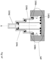
Fig. 1A shows an example cross-section of a frothing appliance. -
Fig. 1A' shows an example of the frothing appliance ofFig. 1A , in use. -
Fig. 1B shows a further example of the frothing appliance ofFig. 1A . -
Fig. 1 B' shows the frothing appliance ofFig. 1B , in use. -
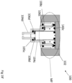
Fig. 1C shows a further example of the frothing appliance ofFigs. 1A and1B . -
Fig. 1C' shows the frothing appliance ofFig. 1C , in use. -
Figs 1A-1C' generally show afrothing appliance 100 that can be integrated with a coffee machine, a drinks dispenser or the like. Thefrothing appliance 100 may also be a standalone appliance or a modular appliance that can be fitted to an existing coffee machine, drinks dispenser or the like. -
Fig. 1A shows an example of a frothingappliance 100. The frothingappliance 100 includes ahousing 102 that has arecess 102a. The frothingappliance 100 also includes afroth wand 104 that has a longitudinal axis, A, and a radial axis, r. Thefroth wand 104 is configured to retract and extend along the longitudinal axis A, as will be described in more detail below.Fig. 1A shows thefroth wand 104 in a fully extended state. - The frothing
appliance 100, generally, includes means for retracting and extending thefroth wand 104 into, and out of, therecess 102a of thehousing 102. In general, when thefroth wand 104 is fully, or partially, retracted into therecess 102a of thehousing 102, means for cleaning the froth wand allows for cleaning of thefroth wand 104 when it is fully, or partially, retracted into therecess 102a of thehousing 102, as will be described in more detail below. - As shown in
Fig. 1A , thefroth wand 104 may include a at least one froth wand portion. For example, thefroth wand 104 includes afirst portion 104a, asecond portion 104b, athird portion 104c and afourth portion 104d. Thefroth wand 104, including thefirst portion 104a, thesecond portion 104b, thethird portion 104c, and thefourth portion 104d may be cylindrical in nature, but other shapes are envisaged. In general, thefirst portion 104a, thesecond portion 104b, thethird portion 104c and thefourth portion 104d of thefroth wand 104 may retract and extend along the longitudinal axis, A, in a manner similar to a telescopic arm. - In the example shown in
Fig. 1A , thefirst portion 104a may be fixed to thehousing 102 such that it is contained within therecess 102a of the housing. Thefirst portion 104a may include afirst portion flange 105a that extends inwardly along the radial axis, r, from thefirst portion 104a. In the example shown inFigure 1A , thefirst portion flange 105a is located at the bottom of thefirst portion 104a. Afirst sealing ring 107a may be coupled to an upper surface thefirst portion flange 105a. In the example shown inFig. 1A , thefirst portion flange 105a is located at the bottom of thehousing 102 and thefirst portion flange 105a extends inwardly along the radial axis, r, into the bottom of therecess 102a. - As shown in
Fig. 1A , thesecond portion 104b of thefroth wand 104 may include a second portionfirst flange 106b and a second portionsecond flange 105b. The second portionfirst flange 106b may be located at the top of thesecond portion 104b and extends outwardly along the radial axis, r. As mentioned above,Fig. 1A shows thefroth wand 104 in a fully extended state. Therefore, in the example shown inFig. 1A , the second portionfirst flange 106b is positioned to be resting on thefirst sealing ring 107a. Since the second portionfirst flange 106b is resting on thefirst sealing ring 107a, which is coupled to an upper surface of thefirst portion flange 105a, leaks are prevented between thefirst portion 104a and thesecond portion 104b of thefroth wand 104. The second portionfirst flange 106b may also be flush with thefirst portion 104a. Therefore, leaks are prevented between thefirst portion 104a and thesecond portion 104b of thefroth wand 104. - The
second portion 104b of thefroth wand 104 may include a second portionsecond flange 105b. The second portionsecond flange 105b may be located at the bottom of thesecond portion 104b and extends inwardly along the radial axis, r, from thesecond portion 104b. In the example shown inFigure 1A , the second portionsecond flange 105b is located at the bottom of thesecond portion 104b. Asecond sealing ring 107b may be coupled to an upper surface the second portionsecond flange 105b. - As shown in
Fig. 1A , thethird portion 104c of thefroth wand 104 may include a third portionfirst flange 106c and a third portionsecond flange 105c. The third portionfirst flange 106c may be located at the top of thethird portion 104c and extends outwardly along the radial axis, r. As mentioned above,Fig. 1A shows thefroth wand 104 in a fully extended state. Therefore, in the example shown inFig. 1A , the third portionfirst flange 106c is positioned to be resting on thesecond sealing ring 107b. Since the third portionfirst flange 106c is resting on thesecond sealing ring 107a, which is coupled to an upper surface of the second portionsecond flange 105b, leaks are prevented between thesecond portion 104b and thethird portion 104c of thefroth wand 104. The third portionfirst flange 106c may also be flush with thesecond portion 104b. Therefore, leaks are prevented between thesecond portion 104b and thethird portion 104c of thefroth wand 104. - The
third portion 104c of thefroth wand 104 may include a third portionsecond flange 105c. The third portionsecond flange 105c may be located at the bottom of thethird portion 104c and extends inwardly along the radial axis, r, from thethird portion 104c. In the example shown inFigure 1A , the third portionsecond flange 105c is located at the bottom of thethird portion 104c. Athird sealing ring 107c may be coupled to an upper surface the third portionsecond flange 105c. - As shown in
Fig. 1A , thefourth portion 104d of thefroth wand 104 may include a fourth portionfirst flange 106d and a fourth portionsecond flange 105d. The fourth portionfirst flange 106d may be located at the top of thefourth portion 104d and extends outwardly along the radial axis, r. As mentioned above,Fig. 1A shows thefroth wand 104 in a fully extended state. Therefore, in the example shown inFig. 1A , the fourth portionfirst flange 106d is positioned to be resting on thethird sealing ring 107c. Since the fourth portionfirst flange 106d is resting on thethird sealing ring 107c, which is coupled to an upper surface of the third portionsecond flange 105c, leaks are prevented between thethird portion 104c and thefourth portion 104d of thefroth wand 104. The fourth portionfirst flange 106d may also be flush with thethird portion 104c. Therefore, leaks are prevented between thethird portion 104c and thefourth portion 104d of thefroth wand 104. - The
fourth portion 104d of thefroth wand 104 may include a fourth portionsecond flange 105d. The fourth portionsecond flange 105d may be located at the bottom of thefourth portion 104d and extends inwardly along the radial axis, r, from thefourth portion 104d. In the example shown inFigure 1A , the fourth portionsecond flange 105d is located at the bottom of thefourth portion 104d. The fourth portionsecond flange 105d may define anoutlet 110 of thefroth wand 104. - In the extended state, steam can be passed through the
froth wand 104 via at least onenozzle 120 located in therecess 102a of thehousing 102. As shown inFig. 1A , the at least onenozzle 120 is located on aninner surface 112 of thehousing 102. The at least onenozzle 120 may be located at the top of therecess 102a of thehousing 102, as shown inFig. 1A . The at least onenozzle 120 may also extend into therecess 102a along the longitudinal axis, A. The at least one nozzle may also be provided on an inner surface (not shown) of thehousing 102 that may allow for the at least one nozzle to extend into therecess 102a of thehousing 102 along the radial axis, r. - The
froth wand 104 may include at least one magnetic or ferromagnetic material that can be used to retract and extend thefroth wand 104. For example, a first magnetic orferromagnetic material 108b may be included on a surface of the second portionfirst flange 106b, a second magnetic orferromagnetic material 108c may be included on a surface of the third portionfirst flange 106c, and a third magnetic orferromagnetic material 108d may be included on a surface of the fourth portionfirst flange 106d. The first magnetic orferromagnetic material 108b, second magnetic orferromagnetic material 108c and the third magnetic orferromagnetic material 108d may be a ferromagnetic ring. Thehousing 102 may be, or include, a solenoid that is configured to switch between an on and off mode, where, in the on mode, a magnetic field is provided around thehousing 102 to attract the at least one magnetic or ferromagnetic material such that thefroth wand 104 may be retracted and extended, as described in further detail below. In the off mode, the magnetic field is not present. - A
spring 130 may be provided extending from theinner surface 112 of thehousing 102, along the longitudinal axis, A, of thefroth wand 104 to maintain thefroth wand 104 in an extended state. In the example shown inFig. 1A , thespring 130 extends from theinner surface 112 of thehousing 102 to an upper surface of the fourth portionfirst flange 106d. Of course, if there were more, or less, than four portions in thefroth wand 104, thespring 130 could extend from theinner surface 112 of thehousing 102 to any of these portions. Thespring 130 is entirely optional and, in the absence of aspring 130, the at least one portion within thefroth wand 104 could extend due to the force of gravity and/or steam pressure. - At least one end stop may be provided on the
inner surface 112 of thehousing 102 to prevent the at least one portion of thefroth wand 104 from extending to the at least onenozzle 120. For example, and as shown inFig. 1A , afirst end stop 140b is in line with the second portionfirst flange 106b, asecond end stop 140c is in line with the third portionfirst flange 106c, and athird end stop 140d is in line with the fourth portionfirst flange 106d. Therefore, as an example, the second portionfirst flange 106b, the third portionfirst flange 106c, and the fourth portionfirst flange 106d are prevented from contacting the at least onenozzle 120 that provides steam. - Referring now to
Fig. 1A' , in conjunction withFig. 1A , a magnetic field, MF, is provided around thehousing 102 by the solenoid. When the magnetic field, MF, is activated, the second portionfirst flange 106b is in range of the magnetic field, MF, and the first magnetic orferromagnetic material 108b causes thesecond portion 104b to move along the longitudinal axis, A, and towards thefirst end stop 140b (e.g. in the direction of the arrows shown within therecess 102a of the housing 102). In turn,third portion 104c andfourth portion 104d also move upwards along the longitudinal axis, A, due to the arrangement of the flanges. For example, and referring toFig. 1A , the upward force of the second portionsecond flange 105b causes the third portionfirst flange 106c to also move upwards. Likewise, the upward force of the third portionsecond flange 105c causes the fourth portionfirst flange 106d to also move upwards. - Referring now to
Fig. 1B , an intermediate phase of retracting thefroth wand 104 is shown as an example. As can be seen inFig. 1B , thesecond portion 104b has been retracted into therecess 102a of thehousing 102 such that the second portionfirst flange 106b is in contact with thefirst end stop 140b. It is envisaged that thesecond portion 104b is fully, or partially, contained in therecess 102a. Now that thesecond portion 104b has been retracted into therecess 102a, the third portionfirst flange 106c and the second magnetic orferromagnetic material 108c are within the area surrounding thehousing 102. As shown inFig. 1B' , the third portionfirst flange 106c and the second magnetic orferromagnetic material 108c are within the magnetic field, MF. When the magnetic field, MF, is activated, the third portionfirst flange 106c is in range of the magnetic field, MF, and the second magnetic orferromagnetic material 108c causes thethird portion 104c to move along the longitudinal axis, A, and towards thesecond end stop 140c (e.g. in the direction of the arrows shown within therecess 102a of the housing 102). In turn, thefourth portion 104d also move upwards along the longitudinal axis, A, due to the arrangement of the flanges. For example, and referring toFig. 1A , the upward force of the third portionsecond flange 105c causes the fourth portionfirst flange 106d to also move upwards. Once thethird portion 104c has moved into therecess 102a, the fourth portionfirst flange 106d and the third magnetic orferromagnetic material 108c will then be within the area surrounding thehousing 102 and, similar to as described above, when the magnetic field, MF, is activated, thefourth portion 104d will also move into therecess 102a of thehousing 102. - As shown in
Fig. 1C , the froth wand is now in a fully retracted state. Thefirst portion 104a, second portion, 104b,third portion 104c andfourth portion 104d are all provided in therecess 102a of thehousing 102. The second portionfirst flange 106b, the third portionfirst flange 106c and the fourth portionfirst flange 106d are in contact with their respective end stops (shown as 140b, 140c and 140d inFig. 1A ). As shown inFig. 1C , the entirety of thefirst portion 104a,second portion 104b,third portion 104c andfourth portion 104d (including their respective flanges, as described above) are contained within therecess 102a of thehousing 102. Of course, it is to be understood that the portions of the froth wand may be partially contained in therecess 102a of thehousing 102. If aspring 130 is present, this would now be fully compressed, as shown inFig. 1C . As shown inFig. 1C' , in conjunction withFig. 1C , the magnetic field, MF, ensures that thefirst portion 104a, thesecond portion 104b, thethird portion 104c and thefourth portion 104d are maintained in therecess 102a of thehousing 102. - Once the
froth wand 104 is in the fully retracted state, a cleaning process may begin. Steam is provided from the at least one nozzle 120 (e.g. the nozzle shown inFig. 1C ) into therecess 102a of thehousing 102. Due to the proximity of the at least one portion of thefroth wand 104 in therecess 102a of thehousing 102, the force of the steam from the nozzle provides cleaning to all components of thefroth wand 104. For example, in this fully retracted state, both the outer parts and the inner parts of the froth wand 104 (including the seal rings) are exposed to the force of the steam which will clean thefroth wand 104 completely (e.g. all internal and external components). Of course, the cleaning process may be initiated at any point of retraction of thefroth wand 104 and is not necessarily limited to thefroth wand 104 being in a fully retracted state (e.g. the cleaning process may be initiated when thefroth wand 104 is at an intermediate phase, as shown inFig. 1B ). - After the cleaning process has been completed, the solenoid in the
housing 102 may be deactivated and the at least one portion of thefroth wand 104 may, due to gravity, return to a fully extended state (e.g. the state shown inFig. 1A ) by at least one portion of thefroth wand 104 moving downward along the longitudinal axis, A. As mentioned above, aspring 130 may be present. When aspring 130 is present, the spring moves from a compressed state to an extended state and the spring assists in moving thefourth portion 104d downward along the longitudinal axis, A, which, in turn, causes thethird portion 104c andsecond portion 104d to move out of therecess 102a and downward along the longitudinal axis until the second portionfirst flange 106b is in contact with thefirst portion flange 105a. Similarly, when the solenoid in thehousing 102 is deactivated, steam may be used to return thefroth wand 104 to a fully extended state. For example, the pressure of the steam may cause thefourth portion 104d to move downward along the longitudinal axis, A, which, in turn, causes thethird portion 104c andsecond portion 104b to move out of therecess 102a and downward along the longitudinal axis until the second portionfirst flange 106b is in contact with thefirst portion flange 105a. - The frothing
appliance 100, as described above, may be a standalone frothing appliance or may be provided to be installed on to a coffee machine, a drinks dispenser or the like. Further, the frothingappliance 100 may be integrated into a coffee machine, a drinks dispenser or the like. The frothingappliance 100 may include a controller (not shown) that can control the solenoid within thehousing 102 to automatically clean thefroth wand 104 after a certain period of time or after a certain number of froth cycles. Further, a user could provide instructions to the frothingappliance 100 for the cleaning process to be initiated. - Advantageously, the frothing appliance described above saves a user valuable time, provides an automated self-cleaning froth wand that can be used on its own or with a coffee machine, drinks dispenser, or the like. Although the frothing appliance allows for self-cleaning, it is to be understood that the self-cleaning process is not only for removing frothing residues or particles from the froth want but it also makes use of steam to decontaminate and kill harmful microorganisms and prevent growth of harmful microorganisms. Further, the frothing appliance reduces waste since no parts would need to be replaced. Further, the frothing appliance reduces waste in that no external cleaning agents and/or cleaning cloths are required to clean the frothing appliance.
- Although this disclosure has been described in terms of preferred examples, it should be understood that these examples are illustrative only and that the claims are not limited to those examples. Those skilled in the art will be able to make modifications and alternatives in view of the disclosure which are contemplated as falling within the scope of the appended claims.
Claims (15)
- A frothing appliance (100), comprising:a housing (102) having a recess (102a);a froth wand (104), wherein the froth wand (104) has a longitudinal axis (A);means for retracting the froth wand (104), along the longitudinal axis (A), into the recess (102a) of the housing (102); andmeans for cleaning the froth wand (104) when the froth wand (104) is fully or partially retracted into the recess (102a) of the housing (102).
- The frothing appliance (100) of claim 1, wherein the froth wand (104) comprises a plurality of portions (104a, 104b, 104c, 104d) arranged in a telescopic manner and wherein the plurality of portions (104a, 104b, 104c, 104d) include at least one magnetic or ferromagnetic material (108b, 108c, 108d).
- The frothing appliance (100) of claim 2, wherein the means for retracting the froth wand (104) comprises at least one solenoid that is configured to switch between an on and an off mode, wherein, in the on mode, a magnetic field is provided around the housing (102) to attract the at least one magnetic or ferromagnetic material (108b, 108c, 108d) such that at least one of the plurality of portions (104b, 104c, 104d) move along the longitudinal axis and into the recess (102a) of the housing (102).
- The frothing appliance (100) of claim 3, wherein the plurality of portions (104a, 104b, 104c, 104d) comprises:a first portion (104a) coupled to an inner surface of the housing (102);a second portion (104b) configured to move along the longitudinal axis, A, within the first portion (104a);a third portion (104c) configured to move along the longitudinal axis, A, within the second portion (104b); anda fourth portion (104d) configured to move along the longitudinal axis, A, within the third portion (104c).
- The frothing appliance (100) of claim 4, wherein the frothing appliance includes a radial axis, r, and wherein:the first portion (104a) includes a first portion flange (105a) that extends inwardly along the radial axis, r, from the first portion (104a), and wherein a first sealing ring (107a) is coupled to an upper surface of the first flange portion (105a);the second portion (104b) includes a second portion first flange (106b) that extends outwardly along the radial axis, r, from the second portion (104b), wherein the second portion first flange (106b) is configured to rest, in an extended state and when the at least one solenoid is in the off mode, on the first sealing ring (107a), and wherein the second portion (104b) includes a second portion second flange (105b) that extends inwardly along the radial axis, r, from the second portion (104b), and wherein a second sealing ring (107b) is coupled to an upper surface of the second portion second flange (105b);the third portion (104c) includes a third portion first flange (106c) that extends outwardly along the radial axis, r, from the third portion (104c), wherein the third portion first flange (106c) is configured to rest, in the extended state and when the at least one solenoid is in the off mode, on the second sealing ring (107b), and wherein the third portion (104c) includes a third portion second flange (105c) that extends inwardly along the radial axis, r, from the third portion (104c), and wherein a third sealing ring (107c) is coupled to an upper surface of the third portion second flange (105c); andthe fourth portion (104d) includes a fourth portion first flange (106d) that extends outwardly along the radial axis, r, from the fourth portion (104d), wherein the fourth portion first flange (106d) is configured to rest, in the extended state and when the at least one solenoid is in the off mode, on the third sealing ring (107c), and wherein the fourth portion (104d) includes a fourth portion second flange (105d) that extends inwardly along the radial axis, r, from the third portion (104c), and wherein the fourth portion second flange (105d) defines an outlet (110).
- The frothing appliance (100) of claim 5, wherein:a first magnetic or ferromagnetic material (108b) is included on a surface of the second portion first flange (106b);a second magnetic or ferromagnetic material (108c) is included on a surface of the third portion first flange (106c); anda third magnetic or ferromagnetic material (108d) is included on a surface of the fourth portion first flange (106d).
- The frothing appliance (100) of claim 6, wherein:
when the at least one solenoid is in the on mode, the first magnetic or ferromagnetic material (108b) is within range of a magnetic field (MF) such that the second portion (104b) is configured to move into the recess (102a); and further wherein:
when the second portion (104b) is within the recess (102a), and when the at least one solenoid is in the on mode, the second magnetic or ferromagnetic material (108c) is within range of the magnetic field (MF) such that the third portion (104c) is configured to move into the recess (102a); and further wherein:
when the third portion (104c) is within the recess (102a), and when the at least one solenoid is in the on mode, the third magnetic or ferromagnetic material (108d) is within range of the magnetic field (MF) such that the fourth portion (104d) is configured to move into the recess (102a). - The frothing appliance (100) of any preceding claim, wherein the means for cleaning includes at least one nozzle (120) located in the recess (102a) of the housing (102).
- The frothing appliance (100) of claim 8, wherein steam is provided from the at least one nozzle (120) and into the recess (102a).
- The frothing appliance (100) of claim 9, further comprising:
at least one stop (140b, 140c, 140d) provided on the inner surface of the housing (102). - The frothing appliance (100) of any preceding claim, further comprising:
a spring (130) that extends from an inner surface of the housing (102) to the froth wand (104). - The frothing appliance (100) of claim 11, when dependent on claim 5, wherein the spring (130) extends from the inner surface of the housing (102) to an upper surface of the fourth portion first flange (106d).
- A hot beverage dispensing machine, comprising:
the frothing appliance (100) of any preceding claim. - A method, the method comprising:providing a housing having a recess;providing a froth wand, wherein the froth wand has a longitudinal axis;retracting the froth wand, along the longitudinal axis, into the recess of the housing; andcleaning the froth wand when the froth wand is retracted into the recess of the housing.
- A method of using the frothing appliance of claim 1, the method comprising:activating the means for retracting the froth wand such that the froth wand is retracted fully or partially into the recess of the housing;activating the means for cleaning when the froth wand is retracted fully or partially into the recess of the housing such that the froth wand is cleaned.
Priority Applications (2)
| Application Number | Priority Date | Filing Date | Title |
|---|---|---|---|
| EP23207513.5A EP4548819A1 (en) | 2023-11-02 | 2023-11-02 | Frothing appliance |
| US18/924,376 US20250143507A1 (en) | 2023-11-02 | 2024-10-23 | Frothing machine |
Applications Claiming Priority (1)
| Application Number | Priority Date | Filing Date | Title |
|---|---|---|---|
| EP23207513.5A EP4548819A1 (en) | 2023-11-02 | 2023-11-02 | Frothing appliance |
Publications (1)
| Publication Number | Publication Date |
|---|---|
| EP4548819A1 true EP4548819A1 (en) | 2025-05-07 |
Family
ID=88689488
Family Applications (1)
| Application Number | Title | Priority Date | Filing Date |
|---|---|---|---|
| EP23207513.5A Pending EP4548819A1 (en) | 2023-11-02 | 2023-11-02 | Frothing appliance |
Country Status (2)
| Country | Link |
|---|---|
| US (1) | US20250143507A1 (en) |
| EP (1) | EP4548819A1 (en) |
Families Citing this family (1)
| Publication number | Priority date | Publication date | Assignee | Title |
|---|---|---|---|---|
| US12453440B2 (en) * | 2021-10-04 | 2025-10-28 | Hamilton Beach Brands, Inc. | Self-cleaning frothing appliance |
Citations (4)
| Publication number | Priority date | Publication date | Assignee | Title |
|---|---|---|---|---|
| US8047125B2 (en) * | 2004-12-21 | 2011-11-01 | Seb S.A. | Coffee maker equipped with a steam nozzle |
| US20170079464A1 (en) * | 2015-09-18 | 2017-03-23 | Starbucks Corporation | Beverage preparation systems and methods |
| US11103100B2 (en) * | 2016-04-04 | 2021-08-31 | Iacabucci HF Aerospace S.p.A. | Cappuccino maker |
| CN110934498B (en) * | 2018-09-24 | 2023-08-29 | Seb公司 | Rotary stirring device of beverage preparation machine |
-
2023
- 2023-11-02 EP EP23207513.5A patent/EP4548819A1/en active Pending
-
2024
- 2024-10-23 US US18/924,376 patent/US20250143507A1/en active Pending
Patent Citations (4)
| Publication number | Priority date | Publication date | Assignee | Title |
|---|---|---|---|---|
| US8047125B2 (en) * | 2004-12-21 | 2011-11-01 | Seb S.A. | Coffee maker equipped with a steam nozzle |
| US20170079464A1 (en) * | 2015-09-18 | 2017-03-23 | Starbucks Corporation | Beverage preparation systems and methods |
| US11103100B2 (en) * | 2016-04-04 | 2021-08-31 | Iacabucci HF Aerospace S.p.A. | Cappuccino maker |
| CN110934498B (en) * | 2018-09-24 | 2023-08-29 | Seb公司 | Rotary stirring device of beverage preparation machine |
Also Published As
| Publication number | Publication date |
|---|---|
| US20250143507A1 (en) | 2025-05-08 |
Similar Documents
| Publication | Publication Date | Title |
|---|---|---|
| US20250143507A1 (en) | Frothing machine | |
| US8844430B2 (en) | Filter holder particularly for espresso coffee machines | |
| RU2768328C2 (en) | Device for preparation of beverages with external cleaning of nozzle | |
| EP3253267B1 (en) | Blender with removable spindle and monitored reservoir | |
| CN107296477B (en) | Intelligent cooking equipment | |
| KR102784223B1 (en) | Ultrasonic cleaner for espresso coffee machine and espresso coffee machine including such cleaner | |
| CN108024648B (en) | Automatic tea maker, system and method for operating an automatic tea maker | |
| KR101558136B1 (en) | Filter basket cleaning apparatus for espresso coffee machine | |
| WO2009135034A1 (en) | Brewer including substance removal assembly | |
| CN111759174A (en) | Automatic tea making machine and working method thereof | |
| US20090013874A1 (en) | Beverage Making Device | |
| US3400824A (en) | Filtering apparatus for used cooking oils | |
| JP3169165U (en) | Container cleaning device | |
| CA2999017C (en) | Device for preparing a filtered coffee beverage | |
| US5271571A (en) | Water driven device for agitating and fragmenting debris in a sink drain | |
| JP7571958B2 (en) | Automatic dishwashing machine | |
| KR20190141187A (en) | Beverage feeder | |
| EP1694179A1 (en) | A beverage making device | |
| US5611261A (en) | Grounds disposal device | |
| US20160089645A1 (en) | Devices for Cleaning Automated Blenders | |
| RU2673348C2 (en) | Outlet valve for institutional kitchen kettle | |
| CN209331827U (en) | Household appliance and filter cup thereof | |
| CN110652266A (en) | High-efficient chopsticks purger | |
| JP5260713B2 (en) | Beverage production equipment | |
| CN112512385A (en) | Beverage dispensing system with enhanced cleaning and residue discharge and method of operation of the system |
Legal Events
| Date | Code | Title | Description |
|---|---|---|---|
| PUAI | Public reference made under article 153(3) epc to a published international application that has entered the european phase |
Free format text: ORIGINAL CODE: 0009012 |
|
| STAA | Information on the status of an ep patent application or granted ep patent |
Free format text: STATUS: THE APPLICATION HAS BEEN PUBLISHED |
|
| AK | Designated contracting states |
Kind code of ref document: A1 Designated state(s): AL AT BE BG CH CY CZ DE DK EE ES FI FR GB GR HR HU IE IS IT LI LT LU LV MC ME MK MT NL NO PL PT RO RS SE SI SK SM TR |
|
| STAA | Information on the status of an ep patent application or granted ep patent |
Free format text: STATUS: REQUEST FOR EXAMINATION WAS MADE |
|
| 17P | Request for examination filed |
Effective date: 20251027 |