EP4546999A1 - Superconducting quantum circuit - Google Patents
Superconducting quantum circuit Download PDFInfo
- Publication number
- EP4546999A1 EP4546999A1 EP22947932.4A EP22947932A EP4546999A1 EP 4546999 A1 EP4546999 A1 EP 4546999A1 EP 22947932 A EP22947932 A EP 22947932A EP 4546999 A1 EP4546999 A1 EP 4546999A1
- Authority
- EP
- European Patent Office
- Prior art keywords
- coupler
- josephson
- qubits
- electrode
- circuit
- Prior art date
- Legal status (The legal status is an assumption and is not a legal conclusion. Google has not performed a legal analysis and makes no representation as to the accuracy of the status listed.)
- Pending
Links
Images







Classifications
-
- G—PHYSICS
- G06—COMPUTING OR CALCULATING; COUNTING
- G06N—COMPUTING ARRANGEMENTS BASED ON SPECIFIC COMPUTATIONAL MODELS
- G06N10/00—Quantum computing, i.e. information processing based on quantum-mechanical phenomena
- G06N10/40—Physical realisations or architectures of quantum processors or components for manipulating qubits, e.g. qubit coupling or qubit control
Definitions
- the present disclosure relates to a superconducting quantum circuit.
- a SQUID (Superconducting Quantum Interference Device) loop of each JPO is driven by a flux pump whose amplitude and frequency are tunable.
- JPA Josephson Parametric Amplifier
- the present specification is directed to a resonator that parametrically oscillates and thus JPA in Figure 4 of NPL 1 is denoted here as JPO.
- a local four-body coupling is realized by a nonlinear inductance of a central Josephson junction JJ (coupler).
- the central Josephson junction JJ in a rotational coordinate system of a two-photon drive (two-photon drive), causes a coupling with the following form.
- C is a capacitance value of a coupling capacitor between the coupler and the qubit.
- NPL 1 C is used as a four-body coupling strength in Equations (1.2) and (1.3), but G is used here to distinguish the coupling strength from the coupling capacitor C or the like.
- JRM Josephson Ring Modulator
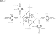
- Fig. 2 is based on Supplementary Figure 8 of NPL 1. It is noted that in Fig. 2 , JPA in Supplementary Figure 8 of Supplementary Note 8 of NPL 1 is denoted as JPO.
- Microwave drive signals with an equal signal strength and reverse phases (indicated by solid and dashed arrow lines for capacitors Cx and Cy) activate a four-body coupling between the JPOs.
- JRM includes two pairs of Josephson junctions (JJs) connected in parallel, each pair being connected in series between a first node which is a connection point of JPO1 and JPO2, and a second node which is a connection point of JPO3 and JPO4.
- a microwave drive signal is applied to each of the first and second nodes via a capacitor Cx, respectively.
- a microwave drive signal with a phase reversed to that of the microwave drive signal applied to the capacitor Cx is applied via a capacitor Cy to each connection point of Josephson junctions (JJ) of the two pair connected in parallel.
- ⁇ d ⁇ p , 1 + ⁇ p , 2 + ⁇ p , 3 ⁇ ⁇ p , 4 for the following drive signal, 2 ⁇ z n cos ⁇ d t (where n is the number of photons (photons) in mode z) under a rotating wave approximation, the following Hamiltonian is derived.
- Equation (1.11) is a term of the four-body interaction.
- Equation (1.12) is a coupling coefficient for a strength of the coupling of the four-body interaction, where n is proportional to a strength of the microwave drive.
- a circuit using a lumped constant type JPO is disclosed in, for example, PTL 2, as illustrated in Fig. 3 .
- Coupler connection portions 124A to 124D of JPO1(120A) to JPO4(120D) and the coupler 121 composed of a Josephson junction (JJ) are capacitively coupled via capacitors (coupling capacitors) 131A to 131D, respectively.
- Readout circuit connection portions 122A to 122D of JPO1 (120A) to JPO4 (120D) are capacitively coupled to readout circuits 140A to 140D via capacitors 132A-132D, respectively.
- JPO1 (120A) to JPO4 (120D) are connected respectively via control lines 123A to 123D to signal generators 150A to 150D that generate pump signals to generate magnetic fluxes that penetrate SQUID loops of JPO1 (120A) to JPO4 (120D).
- a nonlinear element 110 of the coupler 121 is an element that can be regarded as an LC resonator with a Josephson junction (JJ) as a nonlinear inductance.
- the nonlinear element 110 may be a SQUID including two Josephson junctions (JJ).
- NPL 2 A coupler including a circuit similar to a loop circuit of (B) of Fig. 5 described below, is disclosed in NPL 2. However, NPL 2 does not disclose a coupler for a four-body interaction of four qubits. Differences between the present disclosure and that of NPL 2 will be detailed in the example embodiments.
- NPL 1 and PTL 2 illustrated in Fig. 1 to Fig. 3 there is no mention on a method (technique) for strengthening a four-body interaction.
- the configuration in Fig. 2 allows a strength of the four-body interaction to be adjusted but requires another external input(s) (microwave drive signals input with reverse phases to the capacitors Cx and Cy).
- the present disclosure is originated in view of the above issues, and a purpose thereof is to provide a superconducting quantum circuit with a coupler configured to enable to strengthen a four-body interaction by circuit parameters.
- a superconducting quantum circuit includes: first to fourth qubits; and a coupler that couples the first to fourth qubits by a four-body interaction.
- the coupler includes: a loop circuit connected between one end and an other end of the coupler; and a capacitor connected in parallel to the loop circuit, wherein the loop circuit includes: n (n is a positive integer greater than or equal to 2) first Josephson junctions spaced apart from each other and arranged in series; and a second Josephson junction arranged in parallel with the n first Josephson junctions, the second Josephson junction having a junction size smaller than that of the first Josephson junction.
- the first and second qubits are capacitively coupled to the one end of the coupler, respectively, and the third and fourth qubits are capacitively coupled to the other end of the coupler, respectively, wherein a magnitude of a coupling coefficient of the four-body interaction by the coupler is made configurable based on circuit parameters including at least the n and ⁇ (0 ⁇ 1) that is a ratio of a Josephson energy of the second Josephson junction and that of the first Josephson junction.
- a superconducting quantum circuit with a coupler configured to enable to strengthen a four-body interaction by circuit parameters.
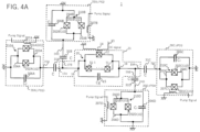
- a superconducting quantum circuit 1 includes four JPOs: JPO 1 (20A) to JPO4 (20D) and a coupler 21.
- JPO 1 (20A) to JPO4 (20D) are connected to the coupler 21 by capacitive coupling via coupling capacitors 31A to 31D, respectively.
- an example of a lumped constant type circuit is described as each JPO, but each JPO may, as a matter of course, be a distributed constant type.
- JPO1 (20A) to JPO4 (20D) include, respectively,
- the second superconducting parts 204A to 204D of JPO1 (20A) to JPO4 (20D) are connected to ground.
- Coupler connection portions 24A and 24B connected to the first superconducting parts 203A and 203B of JPO1 (20A) and JPO2 (20B) are connected to first and second opposing portions 17A and 17B of the coupler 21 via coupling capacitors 31A and 31B, respectively.
- Coupler connection portions 24C and 24D connected to the first superconducting parts 203C and 203D of JPO3 (20C) and JPO4 (20D) are connected to third and fourth opposing portions 19A and 19B of the coupler 21 via coupling capacitors 31C and 31D, respectively.
- the coupler 21 includes
- the loop circuit 10 includes, between the one end (first electrode) 16 and the other end (second electrode) 18 of the coupler 21,
- the magnetic field generation part 14 includes a line (inductor) inductively coupled to the loop circuit 10 of the coupler 21.
- a direct current signal may be supplied to the control line 13 from a current control part not shown to cause the magnetic field generation part 14 to generate a magnetic flux ⁇ ext that penetrates the loop circuit 10 including the first and second Josephson junctions 11-1 to 11-n and the second Josephson junction 12.
- the magnetic field generation part 14 may be made of a coplanar superconducting line or superconducting coil, etc. with one end connected to the control line 13 and the other end connected to ground.
- first Josephson junctions 11-1 to 11-n connected in series are connected such that ends of n+1 adjacent superconducting lines overlap each other, with n overlapping portions, each including a tunnel junction made up of (one end of a superconducting line)/(an insulating film)/(one end of a neighboring superconducting line).
- the other ends of the first and (n+1)-th superconducting lines are connected to the one end (first electrode) 16 and the other end (second electrode) 18 of the coupler 21, respectively.
- Coupler connection portions 24A and 24B of JPO1 (20A) and JPO2 (20B) are capacitively coupled to one end (first electrode) 16 of the coupler 21, respectively, and coupler connection portions 24C and 24D of JPO3 (20C) and JPO4 (20D) are capacitively coupled to the other end (second electrode) 18 of the coupler 21, respectively. That is, in Fig.
- the first and second opposing portions 17A and 17B connected to the one end (first electrode) 16 of the coupler 21 are capacitively coupled to the coupler connection portions 24A and 24B of JPO1 (20A) and JPO2 (20B), respectively, via coupling capacitors 31A and 31B
- the third and fourth opposing portions 19A and 19B connected to the other end (second electrode) 18 of the coupler 21 are capacitively coupled to the coupler connection portions 24C and 24D of PO3 (20C) and JPO4 (20D), respectively, via coupling capacitors 31C and 31D.
- C J denotes a capacitance of the capacitors 206A to 206D of JPO1 (20A) to JPO4 (20D)
- C g denotes a capacitance of the capacitor 15 of the coupler 21
- C denotes a capacitance of coupling capacitors 31A to 31D.
- the coupler 21 is configured to allow a coupling coefficient of the four-body interaction of JPO1 (20A) to JPO4 (20D) to be increased, as will be evident from the following description.
- the first Josephson junction 11 is composed of a portion (tunnel junction) where ends of the superconducting lines 101-1 and 101-2 are in contact with each other via an insulating film (oxide film).
- the second Josephson junction 12 is composed of a portion (tunnel junction) where ends of the superconducting lines 102-1 and 102-2 are in contact with each other via an insulating film (oxide film).
- the superconducting lines 103 and 104 which are connected to the superconducting lines 101-1 and 102-1 and the superconducting lines 101-2 and 102-2, respectively, and the superconducting lines 101-1, 102-1, 101-2 and 102-2 may be the same or different superconducting members.
- E J1 and E J2 are Josephson energies of the first and second Josephson junctions 11 and 12.
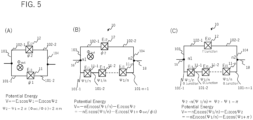
- the loop circuit 10 of the embodiments includes an array of n first Josephson junctions 11-1 to 11-n, spaced each other and connected in series between nodes n1 and n2, and the second Josephson junction 12 connected in parallel with the array.
- the n first Josephson junctions 11-1 to 11-n spaced each other and connected in series are composed of parts (tunnel junctions) where ends of a pair of adjacent lines among n+1 superconducting lines 101-1 to 101-n+1are in contact with each other via an insulating film (oxide film).
- the superconducting lines 101-1 and 101-n+1 are connected to the superconducting lines 103 and 104, respectively.
- the superconducting lines 103 and 104 may constitute the first and second electrodes 16 and 18.
- the second Josephson junction 12 is composed of a portion (tunnel junction) where ends of the superconducting lines 102-1 and 102-2 are in contact with each other via an insulating film (oxide film), as with (A) of Fig. 5 .
- a phase difference ⁇ /n which is obtained by dividing the phase difference ⁇ 1 between the two ends of the array equally, is a phase difference between an input and output at each Josephson junction 11-1 to 11-n.
- ⁇ 0 is a reduced magnetic quantum flux magnetic quantum flux of the above Equation (1.5).
- a Josephson junction has a structure in which a junction barrier layer is sandwiched between two superconductors. An insulating layer or a nonmagnetic metal layer is used as the barrier layer.
- a critical current of the Josephson junction is I 0 and a phase difference across the junction (a phase difference of wave functions in the two superconductors sandwiching the junction) is ⁇
- phase difference ⁇ is 0 rad(radian). For this reason, it is also called a zero junction (0 junction).
- a Josephson junction with a nonmagnetic oxide film (e.g., AlOx) as a junction barrier layer is a zero junction.
- a Josephson junction ferromagnetic Josephson junction
- a ferromagnetic layer e.g., copper-nickel alloy (CuNi) or palladium-nickel alloy (PdNi) or ferromagnetic insulating layer
- CuNi copper-nickel alloy
- PdNi palladium-nickel alloy
- a ⁇ junction alternately change.
- a ⁇ junction is a junction where the following holds.
- a phase difference differs from the zero junction by ⁇ rad in the ground state.
- a thickness dF of the ferromagnetic layer is less than a predetermined value t1
- a state is zero (0)
- t1 ⁇ dF ⁇ t2 a state is ⁇ .
- the phase difference around the loop is ⁇ ⁇ (odd number).
- FIG. 5 schematically illustrates an example of a loop circuit 10 using a ⁇ junction.
- n first Josephson junctions 11-1 to 11-n are zero-junctions and the second Josephson junction 12 is a ⁇ -junction.
- an array of the n first Josephson junctions 11-1 to 11-n connected in series assuming that a phase difference between the two ends of the array (between nodes n1 and n2) is ⁇ 1 and a phase difference at the second Josephson junction 12 is ⁇ 2, then an extra phase difference of ⁇ is generated as compared to the phase difference ⁇ 2 - ⁇ 1 by circumambulation of the loop circuit 10.
- ⁇ 1 ⁇ g
- E J1 E Jg
- E J2 ⁇ E Jg (where 0 ⁇ ⁇ ⁇ 1)
- Equation (2.11) becomes the following Equation (2.16).
- V g ⁇ g ⁇ nE Jg cos ⁇ g n + ⁇ E Jg cos ⁇ g
- the Josephson energy E J2 of the second Josephson junction 12 is set to be ⁇ times (0 ⁇ ⁇ ⁇ 1) each Josephson energy E Jg of the first Josephson junctions 11-1 to 11-n. Since the Josephson energy is proportional to a critical current, the critical current of the second Josephson junction 12 is set to be ⁇ times (0 ⁇ ⁇ ⁇ 1) each critical current I cg of the first Josephson junctions 11-1 to 11-n. A critical current value of a Josephson junction is proportional to a junction size (junction area) of the Josephson junction. Therefore, the junction size of the second Josephson junction 12 is smaller than that of each of the first Josephson junctions 11-1 to 11-n.
- the junction size of the second Josephson junction 12 is ⁇ times (0 ⁇ ⁇ ⁇ 1) a junction size of each of the first Josephson junctions 11-1 to 11-n. The same is also true for a case when n first Josephson junctions 11-1 to 11-n and the second Josephson junction 12 are both zero-junctions, and for a case when n first Josephson junctions 11-1 to 11-n are zero-junctions and the second Josephson junction 12 is a ⁇ -junction.
- Equation (2.16) cosine is subjected to a Tayler expansion, in which up to ⁇ g 4 are considered (higher order terms after ⁇ g 6 are ignored).
- V g ⁇ g ⁇ n ⁇ ⁇ E Jg + E Jg 2 2 ⁇ g 2 ⁇ E Jg 4 24 ⁇ g 4 + O ⁇ g 6
- V g ( ⁇ g ) is expressed as follows. V g ⁇ g ⁇ E Jg 2 2 ⁇ g 2 ⁇ E Jg 4 24 ⁇ g 4
- Fig. 6 illustrates the four-body interaction of four JPO1 (20A) to JPO4 (20D) described with reference to Fig. 3 to Fig. 5 .
- Fig.6 corresponds to Fig. 4A and Fig. 4B .
- the magnetic field generation parts 207A to 207D and 14 of Fig. 4A are not shown.
- Josephson junctions are indicated by symbols with an X surrounded by a square.
- ⁇ 1 to ⁇ 4 in the SQUID loops 210A to 210D of JPO1 (20A) to JPO4 (20D) each represent a magnetic flux that penetrates each SQUID loop.
- E J attached to each of the two Josephson junctions in the SQUID loops 210A to 210D of JPO1 to JPO4 represents the Josephson energy.
- E J ⁇ 2 e I c
- E Jg represents a Josephson energy of the first Josephson junction 11 of the coupler 21 (Equation (2.17)).
- Fluxes ⁇ 1 to ⁇ 4, ⁇ g1, and ⁇ g2 are placed at each node 1 to 4, g1 and g2, respectively (reference may be made to, e.g., NPL3 for fluxes placed at each node).
- C mat -1 is an inverse matrix of a capacitance connection (incidence) matrix (6 rows by 6 columns) C mat in Fig. 6 .
- V coupler V g ⁇ g 1 ⁇ ⁇ g 2 ⁇ 0
- a coordinate ⁇ and a momentum q are quantized using creation and annihilation operators a + and a of a boson (Cooper pair) according to the standard method according to NPL 3, etc.
- Equation (2.34) Ec is a charging energy of the capacitor C J .
- Equation (2.35) E' Cg is an effective energy with an effect of coupling with JPO taken into a charging energy of the capacitor Cg of the coupler 21.
- the coupler 21 has two flux degrees of freedom ⁇ g1 and ⁇ g2 .
- n gZ 1 2 Z g
- Cos( ⁇ i / ⁇ 0 ) in Equation. (2.28) is expressed in terms of creation and annihilation operators of a boson using a Tayler expansion to the fourth order, as follows.
- E J ⁇ i E J + ⁇ E J cos ⁇ p , i t
- Equation (2.29) The function V g in Equation (2.29) is defined by Equation (2.16) and thus contains a term cos(( ⁇ g1 - ⁇ g2 )/ ⁇ 0 ), which is expanded as follows as with Equation (2.42).
- H coupler is a Hamiltonian of the coupler 21 and is given by the following Equation (2.47).
- H coupler ⁇ + a g + ⁇ a g + ⁇ ⁇ + 2 a g + 2 + a g + ⁇ 2 + ⁇ ⁇ a g ⁇ ⁇ a g ⁇ ⁇ E ′ Cg 12 E Jg 4 E Jg 2 a g ⁇ + a g ⁇ ⁇ 4
- ⁇ is a resonant angular frequency of the JPO corresponding to ai
- ⁇ + and ⁇ - are resonant angular frequencies of the coupler 21 corresponding to a g+ and a g- , respectively.
- a difference in an angular frequency between different JPOs is not taken into consideration.
- H total includes an interaction between each JPO and the coupler 21.
- g+ and g- are a strength of an interaction between each JPO and the two degrees of freedom of the coupler 21.
- each JPO interacts with the coupler 21, it can be assumed that JPOs are also indirectly interacted with each other through the interaction with coupler 21.
- an interaction between JPOs 1 to 4 and the coupler 21 is transformed into a four-body interaction among JPOs. That is, it can be transformed to a Hamiltonian with a form in which JPOs are interacting directly with each other.
- This transformation can be expressed as a unitary transformation by the following unitary matrix U.
- the above unitary transformation looks similar to one in NPL 1, but it differs from NPL 1 in that NPL 1 considers only one degree of freedom of the coupler.
- a boson of each JPO is represented by a rotated coordinate system.
- a frequency of rotation of the coordinate system is different for each JPO.
- the coordinate system is represented by one that rotates at half the frequency of a pump signal to generate a magnetic flux penetrating the SQUID loop in each of JPOs 1 to 4.
- the pump frequency is different for each JPO.
- a transition to the rotating coordinate system causes an oscillating term(s) to appear in the Hamiltonian in time, but the oscillating term(s) can be ignored (rotating wave approximation) because they are averaged and their positive and negative values would cancel out on a time scale of interest here.
- Equation (2.50) The Hamiltonian H' total obtained through the above process can be expressed as the following Equation (2.50) by focusing on the four-body interaction term.
- Equation (2.50) is a coefficient (coupling coefficient) representing a strength of coupling of the four-body interaction and expressed by the following Equation (2.51), using:
- Equation (2.52) E c is a charging energy of the capacitance C J of each JPO.
- E C e 2 2 C J
- E J is a Josephson energy of the SQUID of each JPO.
- ⁇ - is a resonant angular frequency of the coupler 21 (resonant angular frequency corresponding to the boson operator a g- ) and is given by ⁇ _ ⁇ 8 E ′ Cg E Jg 2
- the resonant angular frequency ⁇ - of the coupler 21 depends on n and ⁇ , while the resonant frequency ⁇ of each JPO does not depend on n and ⁇ .
- the coupling coefficient g (4) of the four-body interaction becomes smaller.
- a value of ⁇ - needs to be adjusted by a parameter(s) other than n and ⁇ . This can be realized by adjusting a critical current I cg of individual Josephson junctions of the coupler 21.
- the parameters of the Josephson junction are adjusted so that the above frequencies are realized.
- the effect is evaluated by an absolute value of the coupling coefficient g (4) of the four-body interaction. The reason for this is as follows.
- Equation (2.51) regarding the coupling coefficient g (4) of the four-body interaction, the value of g (4) may be negative for some combinations of values of n and ⁇ . However, a sign of g (4) can be changed by adjusting another parameter(s) not explicitly shown here.
- the sign of the coupling coefficient g (4) of the four-body interaction is not essential, and it is sufficient to focus only on the absolute value of g (4)
- a vertical axis is an absolute value of g (4) divided by h/2 ⁇ and converted to MHz (megahertz) unit (h is Planck's constant (about 6.6 x 10 ⁇ (-34) joule-second).
- the other parameters are fixed to the above set values.
- the resonant angular frequency ⁇ - of the coupler 21 is also fixed.
- g (4) is constant regardless of ⁇ .
- the four-body interaction of a qubit made up of JPO is realized.
- adjustment is done for n (the number of first Josephson junctions 11 in the coupler 21) and ⁇ (a ratio of a Josephson energy of the second Josephson junction 12 to that of the first Josephson junction 1, or a ratio of a junction size of the second Josephson junction 12 to that of the first Josephson junction 1), where n and ⁇ are parameters included in the coupling coefficient g (4) of the four-body interaction.
- the coupling coefficient g (4) of the four-body interaction in Equation. (2.51) includes a factor with respect to capacitance C J , C g , and C which belong to circuit parameters, C 4 C J 2 C g + C 3
- the coupling coefficient of the four-body interaction g (4) can be enlarged by setting of the capacitance values C J , C g , and C. This is based on the four-body interaction coupling coefficient according to the example embodiment and is a major difference from NPL 2 directed to a two-body interaction.
- C g + C in a denominator of the coupling coefficient g (4) of the four-body interaction becomes smaller and the value of g (4) becomes larger.
- the capacitance C g of the capacitor 15 of the coupler 21 is made smaller as compared with the capacitance C J of each JPO.
- Figs. 4A and 4B the configuration of the example embodiment is described as a circuit diagram.
- the quantum annealing device will also be described after describing an example of mounting the device on a quantum chip where a superconducting circuit(s) is/are formed in a wiring layer on a substrate.
- Fig. 8 schematically illustrates an example of a configuration of the coupler 21 (wiring pattern formed on a substrate) in a case where JPO1 (20A) to JPO4 (20D) in Fig. 4A are configured as a lumped constant type.
- each JPO of JPO1 (20A) to JPO4 (20D) is composed of the configuration of Fig. 4A and configured as a waveguide resonator terminated to ground by each of the SQUIDs 210A to 210D.
- the waveguide resonator is made to oscillate in a parametric oscillation mode by modulating a magnetic flux penetrating each loop of SQUID 210A to 210D at a frequency approximately twice the resonant frequency with each pump signal (microwave) supplied from each of control lines 23A to 23D.
- the coupler connection portions 24A to 24D extending from the conductive portions (waveguides including superconducting members) 205A to 205D connecting to the first superconducting parts 203A to 203D of the SQUIDs 210A to 210D are capacitively coupled to the ends of the first and second opposing portions 17B, the third and fourth opposing portions 19A and 19B.
- the coupler connection portions 24A to 24D of JPO1 (20A) to JPO4 (20D) may, for example, include a coplanar waveguide with both sides sandwiched by a ground pattern not shown via gaps along the longitudinal direction.
- a ground pattern not shown via gaps along the longitudinal direction.
- the coupler 21 for the four-body interaction includes the first and second opposing portions 17A and 17B extended (elongated) from the first electrode 16 to the two JPOs 1 and 2 (20A, 20B), respectively, and have ends faced to and capacitively coupled to, via coupling capacitors 31A and 31B, ends of the coupler connection portions 24A and 24B of the JPOs 1 and 2 (20A, 20B).
- the second electrode 18 arranged opposing to the first electrode 16 includes third and fourth opposing portions 19A and 19B faced to and capacitively coupled to, via coupling capacitors 31C and 31D, ends of the coupler connection portions 24C and 24D of the JPOs 3 and 4 (20C and 20D).
- the loop circuit 10 that includes n first Josephson junctions 11-1 to 11-n connected in series and a second Josephson junction 12 connected in parallel to the n first Josephson junctions 11-1 to 11-n.
- the ends of the first and second opposing portions 17A and 17B extending from the first electrode 16 and the ends of the coupler connection portions 24A and 24B of JPOs 1 and 2 (20A and 20B), respectively opposed to the ends of the first and second opposing portions 17A and 17B are capacitively coupled via capacitors (coupling capacitors (C) 31A and 31B).
- the ends of the third and fourth opposing portions 19A and 19B and the ends of the coupler connection portions 24C and 24D of JPOs 3 and 4 (20C and 20D) respectively opposed to the ends of the third and fourth opposing portions 19A and 19B are capacitively coupled via capacitors (coupling capacitors (C) 31C and 31D).
- the first and second electrodes 16 and 18 are capacitively coupled via the capacitor (C g ) 15 between the first and second electrodes 16 and 18. There is only a gap present between the first and second electrodes 16 and 18.
- first and second opposing portions 17A and 17B and the third and fourth opposing portions 19A and 19B extend from the two side edges of the rectangular shaped first and second electrodes 16 and 18, respectively, but the planar shape of the first and second electrodes 16 and 18 is, as a matter of course, not limited to a rectangle.
- the coupler 21 and JPO1 (20A) to JPO4 (20D) are realized, for example, by lines (wiring) formed by a superconductor on a substrate.
- the substrate is silicon (Si), but other electronic materials such as sapphire or compound semiconductor materials (Group IV, III-V, II-VI) may be used.
- the substrate may preferably be monocrystalline but may also be polycrystalline or amorphous.
- As the line material (wiring material), Nb (niobium) or Al (aluminum) may be used, for example, but is not limited thereto.
- any metal that becomes a superconducting state when cooled to a very low temperature may be used, such as, niobium nitride, indium (In), lead (Pb), tin (Sn), rhenium (Re), palladium (Pd), titanium (Ti), titanium nitride, Mo (molybdenum), tantalum (Ta), tantalum nitrides, and alloys containing at least one of these, etc.
- a coupler circuit is utilized in a temperature environment of about 10 mK (millikelvin), which is realized by a refrigerator.
- the capacitance value of each capacitor may be set as C J > Cg > C
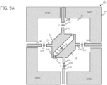
- Fig. 9A illustrates a non-limiting example of the example embodiments described above, and schematically illustrates a non-limiting example of a pattern (planar circuit) of the coupler 21 in Fig. 8 .
- JPO1 to JPO4 are illustrated with their respective coupler connection portions 24A to 24D.
- the coupler 21 is arranged surrounded by a ground pattern (ground plane) 40.
- the coupler connection portions 24A to 24D of JPOs 1 to 4 are surrounded on both sides by the ground pattern (ground plane) 40 via gaps, and the JPOs 1 to 4 themselves are also surrounded by the ground pattern (ground plane) 40.
- the coupler 21 is spaced apart from an edge of the ground pattern (ground plane) 40 by a gap of about a size of the coupler 21 (on the order of a fraction to several times the size), for example. If the coupler 21 is of the order of 10 to 100 ⁇ m (tens to hundreds of ⁇ m), a gap spacing may be approximately of this order.
- 41 is an area where no ground pattern is provided and the substrate is exposed.
- a planar shape of the first electrode 16 is of an almost trapezoidal shape, rotated about 45 degrees counterclockwise with respect to a horizontal direction of the drawing.
- the first and second opposing portions 17A and 17B of the first electrode 16 are extended from oblique sides (legs) of the trapezoid to the left and up in the drawing toward the coupler connection portions 24A and 24B of JPO1 and JPO2, respectively.
- the planar shape of the second electrode 18 is an upside-down trapezoidal shape with the first electrode 16 rotated 180 degrees, and the third and fourth opposing portions 19A and 19B of the second electrode 18 are extended from oblique sides to the right and down in the drawing toward the coupler connection portions 24C and 24D of JPO3 and JPO4, respectively.
- the first electrode 16 and the second electrode 18 are arranged with their respective trapezoidal bottom sides facing each other, and the planar shape of the bodies together, excluding the facing portions, is close to an almost hexagonal shape.
- a protrusion 16C protruding downwardly in the figure, and in a vicinity of the intersection of one end of the bottom of the second electrode 18 and the oblique side, there is a cut portion 18C that is cut off to be parallel to the protrusion 16C of the first electrode 16.
- the loop circuit 10 described with reference to (C) of Fig.5 is arranged (Note that due to the difference in dimensions of the loop circuit 10 and electrodes 16 and 18, the first Josephson junctions 11-1 to 11-n and the second Josephson junction 12 are not shown in the figure).
- the second Josephson junction 12 is a ⁇ -junction and the remaining n first Josephson junctions 11-1 to 11-n are 0-junctions, even without providing a magnetic flux ⁇ 0 /2 penetrating the loop circuit 10, the second Josephson junction 12 potential energy is given by Equation (2.15), and the potential energy V( ⁇ 1) of the loop circuit 10 is the same potential energy as in Equation (2.11).
- Fig. 9B there is provided an additional control line 13 to which a current is supplied from a current control unit not shown to generate a magnetic flux ⁇ ext penetrating the loop circuit 10.
- the control line 13 is configured as a line with a ground pattern 40 arranged via gaps on both sides in a longitudinal direction.
- An end portion of the control line 13 functions as the magnetic field generation part 14 in Fig. 8 and is connected to ground (ground pattern 40) in a vicinity of the loop circuit 10. Therefore, adjacent to the loop circuit 10, the ground pattern 40 has a region 30 that protrudes inwardly to become closer to the loop circuit 10.
- a distance between the part of the electrode and the ground pattern 40 is reduced.
- the control line 13 is formed in the vicinity of the loop circuit 10 and thus the magnetic flux ⁇ ext can be applied from an immediate vicinity of the loop circuit 10.
- the ground pattern 40 is basically separated from the first and second electrodes 16 and 18, as with Fig.9A , except for the region 30 that is arranged closer to the loop circuit 10.
- control line 13 and the magnetic field generation part 14 may be provided at or near a position opposing to the loop circuit 10 of the coupler 21, on a surface of a wiring substrate (interposer) not shown on which a quantum chip including the coupler 21 is flip-chip mounted via bumps.
- the capacitance C J of the capacitors of JPO1 (20A) to JPO4 (20D) (201A to 201D in Fig. 4A ) , the capacitance Cg of the capacitor of the coupler 21 (15 in Fig. 4A ), and the capacitance C of the coupling capacitors (31A to 31D in Fig. 4A ) between the coupler connection portions 24A to 24D and the opposing portions 17A, 17B, 19A, and 19B of the coupler 21, may be set as follows.
- NPL 2 a coupling device with a superconducting loop circuit with an array of n first Josephson junctions connected in series and a second Josephson junction connected in parallel with the array is disclosed.
- the following describes comparison of the disclosure of the present application with the disclosure of NPL 2. The following points are common.
- the structure of the loop circuit of the coupler 21 is also used as a coupler structure between qubits (or photons) also in NPL 2.
- a type of interaction generated by the coupler 21 is different.
- the disclosure of the present application utilizes the coupler 21 to generate the four-body interaction of a qubit (JPO), whereas NPL 2 utilizes this coupler to generate the two-body interaction of a qubit (the four-body interaction coupler is not described at all in NPL 2).
- JPO qubit
- NPL 2 utilizes this coupler to generate the two-body interaction of a qubit
- capacitors are needed to distinguish between JPO1 and JPO2, and between JPO3 and JPO4 whose connection can be done without the coupler targeted to the four-body interaction.
- a coupling capacitor is needed between the qubit (JPO).
- the devise of adjusting the value of the resonant angular frequency ⁇ - of the coupler 21 (such that it does not change) in order to enlarge the strength of the four-body interaction (coupling coefficient) is specific to the present application.
- the coupler is directed to the two-body interaction, which is different from four-body interaction. Therefore, ⁇ (quarton), etc. in Equation (7) of the coupling coefficients of the interaction in NPL 2 are completely different from the above described coupling coefficient g (4) of the four-body interaction in Equation (2.51) of the present application.
- the disclosure of the present application is directed to the four-body interaction of qubits, whereas the NPL 2 is directed to the two-body interaction of qubits. Due to this point, there are differences regarding presence or absence of a capacitor between the qubit and the coupler, presence or absence of resonance of the coupler, presence or absence of the need to adjust the resonant frequency of the coupler, and the expression (equation) of the interaction coefficient.
- the coupling capacitance C between each JPO and coupler 21, and the capacitance C g of the coupler 21 setting is done such that C J > C g > C.
- the coupling coefficient g (4) of the four-body interaction can be made large.
- Fig. 10 is a schematic diagram of a quantum computer 300 in which JPOs 20 are integrated, as an example configuration of another example embodiment.
- each four-body interaction coupler 21 is connected to four JPO 20s, as illustrated in Figs. 4A , 4B and 8 , respectively.
- the unit structures illustrated in Fig. 4A , Fig. 4B , Fig. 8 , etc. are arranged such that each JPO 20 is connected to one to four couplers 21 for a four-body interaction, and JPO 20 is shared and arranged by multiple unit structures.
- at least one JPO 20 is connected to a plurality of couplers 21 for a four-body interaction.
- Fig. 10 is a schematic diagram of a quantum computer 300 in which JPOs 20 are integrated, as an example configuration of another example embodiment.
- each four-body interaction coupler 21 is connected to four JPO 20s, as illustrated in Figs. 4A , 4B and 8 , respectively.
- the quantum computer 300 may also be described as follows.
- the quantum computer 300 has a plurality of JPOs 20, each JPO 20 being connected to one to four couplers 21 for a four-body interaction.
- the number of couplers 21 for a four-body interaction to which each JPO 20 is connected corresponds to how many of the JPOs 20 are shared in the unit structure.
- the quantum computer 300 has multiple unit structures and the JPO 20 is shared by multiple unit structures.
- 13 superconducting nonlinear JPOs 20 are integrated, but any number of JPOs 20 can be integrated in a similar manner.
- a current control part and a readout part are omitted for ease of understanding of the drawing, but JPO 20 is controlled and read out using a current control part and a readout part as described with reference to Fig. 3 .
- a superconducting quantum circuit includes first through fourth qubits and a coupler that couples the first through fourth qubits by a four-body interaction.
- the coupler includes a loop circuit connected between one end and an other end of the coupler; a capacitor connected in parallel to the loop circuit.
- the loop circuit includes n (n is a positive integer greater than or equal to 2) first Josephson junctions spaced apart from each other and arranged in series, and n (n is a positive integer greater than or equal to 2); a second Josephson junction arranged in parallel with the n first Josephson junctions and having a junction size smaller than that of the first Josephson junction.
- the first and second qubits are capacitively coupled to the one end of the coupler, respectively and the third and fourth qubits are capacitively coupled to the other end of the coupler, respectively.
- a magnitude of the coupling coefficient of the four-body interaction by the coupler is set based on circuit parameters including at least n and ⁇ (0 ⁇ ⁇ 1) which is a ratio of a Josephson energy of the second Josephson junction and that of the first Josephson junction.
- the ⁇ may be set to a predetermined value close to 1/n within a range smaller than 1/n which is an inverse of n.
- the superconducting quantum circuit according to Note 1 or 2 may include a magnetic field generation part that flows a DC current fed from a current control part to generate ⁇ 0 /2 or - ⁇ 0 /2 as a magnetic flux that penetrates the loop circuit of the coupler.
- an odd number (2k+1, where k is a predetermined non-negative integer) of the n first and second Josephson junctions of the loop circuit may be ⁇ junctions and rest may be 0 junctions.
- a phase difference when circumventing the loop circuit is ⁇ ⁇ ⁇ (2k+1)
- the loop circuit of the coupler has a first electrode and a second electrode arranged opposite each other spaced apart from a ground pattern in an area surrounded by the ground pattern in a wiring layer on a substrate.
- the n (n being two or more positive integers) first Josephson junctions and the second Josephson junction, and are arranged in parallel between the first electrode and the second electrode, respectively.
- the first electrode may include first and second opposing portions extended towards the first and second qubits from locations of the first electrode other than a side of the first electrode faced to the second electrode, respectively, the first and second opposing portions having ends capacitively coupled to ends of coupler connection portions of the first and second qubits, respectively.
- the second electrode may include third and fourth opposing portions extended towards the third and fourth qubits from locations of the second electrode other than a side of the second electrode faced to the first electrode, respectively, the third and fourth opposing portions having ends capacitively coupled to ends of coupler connection portions of the third and fourth qubits, respectively.
- each of the first and fourth qubits includes a Josephson parametric oscillator, wherein the Josephson parametric oscillator includes
- the circuit parameter defining the coupling coefficient of the four-body interaction includes, in addition to the ⁇ and the n,
- a superconducting quantum circuit apparatus wherein the superconducting quantum circuit according to any one of Notes 1 to 8, constitute a quantum computer that includes, as a unit structure, the first to fourth qubits that perform Josephson parametric oscillation; and the coupler.
- the superconducting quantum circuit apparatus as according to Note 9, wherein a plurality of the unit structures are provided, and the unit structure may constitute a quantum computer in which at least one of the first through fourth qubits are shared by one or more other the unit structures.
Landscapes
- Engineering & Computer Science (AREA)
- General Physics & Mathematics (AREA)
- Theoretical Computer Science (AREA)
- Physics & Mathematics (AREA)
- Mathematical Analysis (AREA)
- Data Mining & Analysis (AREA)
- Evolutionary Computation (AREA)
- Condensed Matter Physics & Semiconductors (AREA)
- Computational Mathematics (AREA)
- Mathematical Optimization (AREA)
- Pure & Applied Mathematics (AREA)
- Computing Systems (AREA)
- General Engineering & Computer Science (AREA)
- Mathematical Physics (AREA)
- Software Systems (AREA)
- Artificial Intelligence (AREA)
- Superconductor Devices And Manufacturing Methods Thereof (AREA)
Abstract
Description
- The present disclosure relates to a superconducting quantum circuit.
- As a method for solving a combinatorial optimization problem, there is a quantum annealing. As one of schemes of the quantum annealing, there is one called LHZ (Lechner, Hauke, Zoller) scheme (see, e.g., Patent Literature (PTL) 1). In order to physically implement an LHZ scheme-based quantum annealing, it is necessary to realize a qubit (quantum bit) which is a basic element, and a network of qubits, especially a network in which four qubits interact with each other simultaneously (four-body interaction). As one of implementation modes, a method (technique) using a Josephson Parametric Oscillator (JPO) as a qubit has been proposed (see, e.g., Non-Patent Literature (NPL) 1).
-
- (a) One of the methods can realize a four-body interaction with a simple structure, as illustrated in
Fig. 1. Fig. 1 is based on Figure a inFigure 4 ofNPL 1.Fig. 1 illustrates a system in which JPO1 to JPO4 with resonant angular frequencies ωr,i (i=1,2,3,4) interact through a single Josephson junction (JJ) (JPO1 to JPO4 with different resonant angular frequencies are illustrated with different patterns according toFigure. 4 of NPL 1). - A SQUID (Superconducting Quantum Interference Device) loop of each JPO is driven by a flux pump whose amplitude and frequency are tunable. An angular frequency ωp , k(t) (k=1,2,3,4) of the pump signal, is set to nearly twice an angular frequency of a resonator: 2 ωr,i. In a Josephson Parametric Amplifier (JPA), there is a certain threshold for a strength of a pump. When the strength of the pump exceeds the threshold, JPA begins to oscillate and output a signal with a resonant angular frequency ωr,i even when no input signal is present. This is called a parametric oscillation. The present specification is directed to a resonator that parametrically oscillates and thus JPA in
Figure 4 ofNPL 1 is denoted here as JPO. - A local four-body coupling is realized by a nonlinear inductance of a central Josephson junction JJ (coupler).
- As angular frequencies of the pump signals for JPO1 to JPO4, selection thereof is done as follows to detune the resonators.

- Assuming that the pump signals for JPO1 to JPO4 are detuned from each other, the central Josephson junction JJ (coupler), in a rotational coordinate system of a two-photon drive (two-photon drive), causes a coupling with the following form.

- This four-body interaction is always active and its strength G depends on a nonlinearity of the central Josephson junction JJ and a detuning of the resonators including JPO and the Josephson junction JJ. It is noted that ai (i=1 to 4) is an annihilation operator of a resonance mode (boson) of
JPOs 1 to 4, and ai + (i=1 to 4) is a creation operator.
G in Equation (1.2) is given by
- In Equation (1.3),
- Δk (k=1,2,3,4) is a difference (detuning) between a mode angular frequency ωr,k of k-th JPO and a mode angular frequency (resonant angular frequency) ωc defined by a capacitance and an inductance of the central Josephson junction JJ (coupler).

- ϕ0 is a magnetic flux quantum (reduced magnetic quantum flux):


- In Equation (1.3),
- ϕ c is a standard deviation of a zero-point flux variation of the JJ mode.
- EJ is a Josephson energy of the central Josephson junction JJ and is proportional to a critical current Ic of the Josephson junction.

- gk (k=1,2,3,4) expresses a magnitude of coupling of a k-th JPO with a mode of the central Josephson junction JJ.

- In Equation (1.8), ϕ k (k=1,2,3,4) is a zero-point flux variation of the JPO mode,
- C is a capacitance value of a coupling capacitor between the coupler and the qubit.
- It is noted that in
NPL 1, C is used as a four-body coupling strength in Equations (1.2) and (1.3), but G is used here to distinguish the coupling strength from the coupling capacitor C or the like. InNPL 1, a method of strengthening a four-body interaction is not clear with respect to the configuration ofFig. 1 .
(b) The other method uses a Josephson Ring Modulator (JRM), as illustrated inFig. 2. Fig. 2 is based on SupplementaryFigure 8 ofNPL 1. It is noted that inFig. 2 , JPA in SupplementaryFigure 8 of Supplementary Note 8 ofNPL 1 is denoted as JPO. Microwave drive signals with an equal signal strength and reverse phases (indicated by solid and dashed arrow lines for capacitors Cx and Cy) activate a four-body coupling between the JPOs. - In the example in
Fig. 2 , a tunable four-body interaction is realized by using an unbalanced shunt-type JRM. JRM includes two pairs of Josephson junctions (JJs) connected in parallel, each pair being connected in series between a first node which is a connection point of JPO1 and JPO2, and a second node which is a connection point of JPO3 and JPO4. A microwave drive signal is applied to each of the first and second nodes via a capacitor Cx, respectively. A microwave drive signal with a phase reversed to that of the microwave drive signal applied to the capacitor Cx is applied via a capacitor Cy to each connection point of Josephson junctions (JJ) of the two pair connected in parallel. - In this case, in order to implement a four-body interaction, when a combination of oscillation angular frequencies to be met by JPO1 to JPO4 and an angular frequency ωd of the drive signal input from capacitors Cx and Cy is, for example, as follows,


under a rotating wave approximation, the following Hamiltonian is derived.

where
- The second term on the right side of Equation (1.11) is a term of the four-body interaction. Equation (1.12) is a coupling coefficient for a strength of the coupling of the four-body interaction, where

- As a configuration of a related art similar to
Fig. 1 , a circuit using a lumped constant type JPO is disclosed in, for example,PTL 2, as illustrated inFig. 3 . - Referring to
Fig. 3 , four JPO1(120A) to JPO4(120D) and acoupler 121 are provided.Coupler connection portions 124A to 124D of JPO1(120A) to JPO4(120D) and thecoupler 121 composed of a Josephson junction (JJ) are capacitively coupled via capacitors (coupling capacitors) 131A to 131D, respectively. Readoutcircuit connection portions 122A to 122D of JPO1 (120A) to JPO4 (120D) are capacitively coupled toreadout circuits 140A to 140D viacapacitors 132A-132D, respectively. JPO1 (120A) to JPO4 (120D) are connected respectively viacontrol lines 123A to 123D tosignal generators 150A to 150D that generate pump signals to generate magnetic fluxes that penetrate SQUID loops of JPO1 (120A) to JPO4 (120D). Anonlinear element 110 of thecoupler 121 is an element that can be regarded as an LC resonator with a Josephson junction (JJ) as a nonlinear inductance. Thenonlinear element 110 may be a SQUID including two Josephson junctions (JJ). - A coupler including a circuit similar to a loop circuit of (B) of
Fig. 5 described below, is disclosed inNPL 2. However, NPL 2 does not disclose a coupler for a four-body interaction of four qubits. Differences between the present disclosure and that ofNPL 2 will be detailed in the example embodiments. -
- [PTL 1] International Publication No. 2017/001404
- [PTL 2] International Publication No. 2021/014885
-
- [NPL 1] Shruti Puri, et. al, "Quantum annealing with all-to-all connected nonlinear oscillators", Nature Communications 8, 15785 (2017)
- [NPL 2] Yufeng Ye, et. al, "Engineering Purely Nonlinear Coupling between Superconducting Qubits Using a Quarton", PHYSICAL REVIEW LETTERS 127, 050502 (2021)
- [NPL 3] Uri Vool, et. al, "Introduction to Quantum Electromagnetic Circuits", International Journal of Circuit Theory and )
- [NPL 4] T Yamashita, et. al, "Superconducting π qubits with three Josephson junctions", Appl. Phys. Lett. 88, 132501 (2006)
- [NPL 5] V. V. Ryazanov, et.al, "Coupling of Two Superconductors through a Ferromagnet: Evidence for a π Junction", Phys. Rev. Lett. 86, 2427 - Published 12 March 2001
- In
NPL 1 andPTL 2 illustrated inFig. 1 to Fig. 3 , there is no mention on a method (technique) for strengthening a four-body interaction. The configuration inFig. 2 allows a strength of the four-body interaction to be adjusted but requires another external input(s) (microwave drive signals input with reverse phases to the capacitors Cx and Cy). - The present disclosure is originated in view of the above issues, and a purpose thereof is to provide a superconducting quantum circuit with a coupler configured to enable to strengthen a four-body interaction by circuit parameters.
- According to an aspect of the present disclosure, a superconducting quantum circuit includes: first to fourth qubits; and a coupler that couples the first to fourth qubits by a four-body interaction. The coupler includes: a loop circuit connected between one end and an other end of the coupler; and a capacitor connected in parallel to the loop circuit, wherein the loop circuit includes: n (n is a positive integer greater than or equal to 2) first Josephson junctions spaced apart from each other and arranged in series; and a second Josephson junction arranged in parallel with the n first Josephson junctions, the second Josephson junction having a junction size smaller than that of the first Josephson junction. The first and second qubits are capacitively coupled to the one end of the coupler, respectively, and the third and fourth qubits are capacitively coupled to the other end of the coupler, respectively, wherein a magnitude of a coupling coefficient of the four-body interaction by the coupler is made configurable based on circuit parameters including at least the n and α (0<α<1) that is a ratio of a Josephson energy of the second Josephson junction and that of the first Josephson junction.
- According to the present disclosure, there is provided a superconducting quantum circuit with a coupler configured to enable to strengthen a four-body interaction by circuit parameters.
-
-
Fig. 1 is a diagram schematically illustrating a related art. -
Fig. 2 is a diagram schematically illustrating a related art. -
Fig. 3 is a diagram schematically illustrating a related art. -
Fig. 4A is a diagram schematically illustrating an example of embodiments. -
Fig. 4B is a diagram schematically illustrating another example of embodiments. - (A), (B), and (C) of
Fig. 5 are diagrams illustrating embodiments. -
Fig. 6 is a diagram illustrating embodiments. -
Fig. 7 is a diagram illustrating a strength of embodiments. -
Fig. 8 is a diagram schematically illustrating embodiments. -
Fig. 9A is a diagram schematically illustrating one example of a coupler of example embodiments. -
Fig. 9B is a diagram schematically illustrating another example of a coupler of example embodiments. -
Fig. 10 is a diagram schematically illustrating embodiments. - The following describes several embodiments.
Fig. 4A is a diagram illustrating one embodiment. Referring toFig. 4A , a superconductingquantum circuit 1 includes four JPOs: JPO 1 (20A) to JPO4 (20D) and acoupler 21. JPO 1 (20A) to JPO4 (20D) are connected to thecoupler 21 by capacitive coupling viacoupling capacitors 31A to 31D, respectively. In the following embodiments, an example of a lumped constant type circuit is described as each JPO, but each JPO may, as a matter of course, be a distributed constant type. - JPO1 (20A) to JPO4 (20D) include, respectively,
- SQUID (SQUID loop) 210A to 210D, in which first
superconducting parts 203A to 203D,first Josephson junctions 201A to 201D, secondsuperconducting parts 204A to 204D, andsecond Josephson junctions 202A to 202D are connected in a loop; - magnetic
field generation parts 207A to 207D including lines (inductors) inductively coupled to theSQUID loops 210A to 210D respectively, through which pump signals supplied to controllines 23A to 23D from signal generators not shown flow to generate magnetic fluxes that penetrate theSQUID loops 210A to 210D; and -
capacitors 206A to 206D connected, respectively, between the firstsuperconducting parts 203A to 203D and the secondsuperconducting parts 204A to 204D. - The second
superconducting parts 204A to 204D of JPO1 (20A) to JPO4 (20D) are connected to ground. -
Coupler connection portions superconducting parts portions coupler 21 viacoupling capacitors -
Coupler connection portions superconducting parts portions coupler 21 viacoupling capacitors - The
coupler 21 includes - a
loop circuit 10 that is connected to one end (first electrode) 16 and the other end (second electrode) 18 of thecoupler 21 and includes a plurality of Josephson junctions (JJs); and - a
capacitor 15 that is connected in parallel to theloop circuit 10. - More specifically, the
loop circuit 10 includes, between the one end (first electrode) 16 and the other end (second electrode) 18 of thecoupler 21, - first Josephson junctions 11-1 to 11-n that are connected in series and separated each other, and
- a
second Josephson junction 12 that is connected in parallel with the first Josephson junctions 11-1 to 11-n between the one end (first electrode) 16 and the other end (second electrode) 18 of thecoupler 21. - The magnetic
field generation part 14 includes a line (inductor) inductively coupled to theloop circuit 10 of thecoupler 21. A direct current signal may be supplied to thecontrol line 13 from a current control part not shown to cause the magneticfield generation part 14 to generate a magnetic flux Φext that penetrates theloop circuit 10 including the first and second Josephson junctions 11-1 to 11-n and thesecond Josephson junction 12. The magneticfield generation part 14 may be made of a coplanar superconducting line or superconducting coil, etc. with one end connected to thecontrol line 13 and the other end connected to ground. - In the
coupler 21 ofFig. 4A , n first Josephson junctions 11-1 to 11-n connected in series are connected such that ends of n+1 adjacent superconducting lines overlap each other, with n overlapping portions, each including a tunnel junction made up of (one end of a superconducting line)/(an insulating film)/(one end of a neighboring superconducting line). The other ends of the first and (n+1)-th superconducting lines are connected to the one end (first electrode) 16 and the other end (second electrode) 18 of thecoupler 21, respectively. -
Coupler connection portions coupler 21, respectively, andcoupler connection portions coupler 21, respectively. That is, inFig. 4A , the first and second opposingportions coupler 21 are capacitively coupled to thecoupler connection portions coupling capacitors portions coupler 21 are capacitively coupled to thecoupler connection portions coupling capacitors - CJ denotes a capacitance of the
capacitors 206A to 206D of JPO1 (20A) to JPO4 (20D), Cg denotes a capacitance of thecapacitor 15 of thecoupler 21, and C denotes a capacitance ofcoupling capacitors 31A to 31D. - In the embodiments of the disclosure, the
coupler 21 is configured to allow a coupling coefficient of the four-body interaction of JPO1 (20A) to JPO4 (20D) to be increased, as will be evident from the following description. - As illustrated in (A) of
Fig. 5 , in the SQUID, thefirst Josephson junction 11 is composed of a portion (tunnel junction) where ends of the superconducting lines 101-1 and 101-2 are in contact with each other via an insulating film (oxide film). Thesecond Josephson junction 12 is composed of a portion (tunnel junction) where ends of the superconducting lines 102-1 and 102-2 are in contact with each other via an insulating film (oxide film). Thesuperconducting lines - In a case where a magnetic flux Φext penetrates the loop of the SQUID in (A) of
Fig. 5 , assuming that phase differences of the first andsecond Josephson junctions 
- In Equation (2.1),
ϕ0 is a magnetic flux quantum as according to Equation (1.5).
From Equation (2.1),
- A potential energy V(φ1) of the SQUID loop in (A) of
Fig.5 is given by
- In Equation (2.3),
EJ1 and EJ2 are Josephson energies of the first andsecond Josephson junctions 
where IC,i (i=1,2) are critical currents of the first andsecond Josephson junctions - As illustrated in (B) of
Fig. 5 , theloop circuit 10 of the embodiments includes an array of n first Josephson junctions 11-1 to 11-n, spaced each other and connected in series between nodes n1 and n2, and thesecond Josephson junction 12 connected in parallel with the array. The n first Josephson junctions 11-1 to 11-n spaced each other and connected in series are composed of parts (tunnel junctions) where ends of a pair of adjacent lines among n+1 superconducting lines 101-1 to 101-n+1are in contact with each other via an insulating film (oxide film). The superconducting lines 101-1 and 101-n+ 1 are connected to thesuperconducting lines superconducting lines second electrodes second Josephson junction 12 is composed of a portion (tunnel junction) where ends of the superconducting lines 102-1 and 102-2 are in contact with each other via an insulating film (oxide film), as with (A) ofFig. 5 . - As for the array of the n first Josephson junctions 11-1 to 11-n connected in series, if a phase difference between two ends of the array (between nodes n1 and n2) is φ1 and a phase difference at the
second Josephson junction 12 is φ2, the above Equation (2.2) holds. A phase difference φ/n which is obtained by dividing the phase difference φ1 between the two ends of the array equally, is a phase difference between an input and output at each Josephson junction 11-1 to 11-n. By summing individual potential energies of the n first Josephson junctions 11-1 to 11-n,

- It is known that the above Equation (2.6) holds when a capacitance of each
first Josephson junction 11 is ignored. That is, assuming that the capacitance of the first Josephson junction is C1, the above Equation (2.6) holds under a condition that with respect to a charging energy Ec = e2/ (2C1), the following hold, and
assuming a capacitance between the array of the first 11-1 to 11-n Josephson junctions and ground is Cs, the following holds.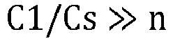
NPL 2,NPL 3, etc.). - When the magnetic flux Φext penetrates the
loop circuit 10 in (B) ofFig. 5 , the potential energy is given as follows.
- Here, the magnetic flux Φext penetrating the
loop circuit 10 is assumed to be given as follows.
- In Equation (2.8), Φ0 is a magnetic flux quantum.

- ϕ 0 is a reduced magnetic quantum flux magnetic quantum flux of the above Equation (1.5).
- From Equation (2.8),

- Therefore, from


- A Josephson junction has a structure in which a junction barrier layer is sandwiched between two superconductors. An insulating layer or a nonmagnetic metal layer is used as the barrier layer. In this case, assuming that a critical current of the Josephson junction is I0 and a phase difference across the junction (a phase difference of wave functions in the two superconductors sandwiching the junction) is φ, a superconducting current (Josephson current) is given as

- In a ground state (Is = 0), the phase difference φ is 0 rad(radian). For this reason, it is also called a zero junction (0 junction). A Josephson junction with a nonmagnetic oxide film (e.g., AlOx) as a junction barrier layer is a zero junction.
- In contrast, in a Josephson junction (ferromagnetic Josephson junction) using a ferromagnetic layer (e.g., copper-nickel alloy (CuNi) or palladium-nickel alloy (PdNi) or ferromagnetic insulating layer) as a barrier layer between the first and second superconductors, depending on a thickness of the ferromagnetic layer, a zero junction and a π junction alternately change.
- Here, a π junction is a junction where the following holds.

- (C) of
Fig. 5 schematically illustrates an example of aloop circuit 10 using a π junction. Although not limited thereto, in the example of (C) ofFig. 5 , n first Josephson junctions 11-1 to 11-n are zero-junctions and thesecond Josephson junction 12 is a π-junction. As for an array of the n first Josephson junctions 11-1 to 11-n connected in series, assuming that a phase difference between the two ends of the array (between nodes n1 and n2) is φ1 and a phase difference at thesecond Josephson junction 12 is φ2, then an extra phase difference of π is generated as compared to the phase difference φ2 - φ1 by circumambulation of theloop circuit 10. Thus, the following holds.
second Josephson junction 12 is,
loop circuit 10 is identical to the above Equation (2.11). That is, in a case where theloop circuit 10 is configured to include an odd number of π junctions (in (C) ofFig. 5 , there is one π junction), without applying an external magnetic flux Φext to the loop circuit 10 (with the magnetic flux Φext = 0), theloop circuit 10 can be set in a state equivalent to be biased with the magnetic flux Φ0/2 (or -Φ0/2) (where Φ0 (=h/(2e)is a magnetic flux quantum). Therefore, when theloop circuit 10 is configured to include an odd number of π junctions, the magneticfield generation part 14 andcontrol line 13 ofFig. 4A are unnecessary, as illustrated inFig. 4B . - Regarding a potential energy of the
loop circuit 10 of thecoupler 21 inFig.4A orFig.4B , the following notations are used in (B) or (C) ofFig.5 .
φ1 = φ g , EJ1 = EJg, EJ2 = αEJg (where 0 < α < 1) - Equation (2.11) becomes the following Equation (2.16).

- In Equation (2.16), each Josephson energy EJg of the first Josephson junctions 11-1 to 11-n is given as

- The Josephson energy EJ2 of the
second Josephson junction 12 is set to be α times (0 < α < 1) each Josephson energy EJg of the first Josephson junctions 11-1 to 11-n. Since the Josephson energy is proportional to a critical current, the critical current of thesecond Josephson junction 12 is set to be α times (0 < α < 1) each critical current Icg of the first Josephson junctions 11-1 to 11-n. A critical current value of a Josephson junction is proportional to a junction size (junction area) of the Josephson junction. Therefore, the junction size of thesecond Josephson junction 12 is smaller than that of each of the first Josephson junctions 11-1 to 11-n. The junction size of thesecond Josephson junction 12 is α times (0 < α < 1) a junction size of each of the first Josephson junctions 11-1 to 11-n. The same is also true for a case when n first Josephson junctions 11-1 to 11-n and thesecond Josephson junction 12 are both zero-junctions, and for a case when n first Josephson junctions 11-1 to 11-n are zero-junctions and thesecond Josephson junction 12 is a π-junction. - In Equation (2.16), cosine is subjected to a Tayler expansion, in which up to


- where


- The first term on the right side of Equation (2.18) is a constant term and does not affect the later discussion and thus by ignoring the first term, Vg(φ g) is expressed as follows.

- In a case where n = 1 and α = 0, there is provided a single first Josephson junction, corresponding to the coupler in
NPL 1, and the following holds.
- In a case where n >= 2, EJg (2) ≠ EJg (4). This difference affects the coupling coefficient of the four-body interaction.
-
Fig. 6 illustrates the four-body interaction of four JPO1 (20A) to JPO4 (20D) described with reference toFig. 3 to Fig. 5 .Fig.6 corresponds toFig. 4A andFig. 4B . InFig. 6 , the magneticfield generation parts 207A to 207D and 14 ofFig. 4A are not shown. InFig. 6 , Josephson junctions are indicated by symbols with an X surrounded by a square. Φ1 to Φ4 in theSQUID loops 210A to 210D of JPO1 (20A) to JPO4 (20D) each represent a magnetic flux that penetrates each SQUID loop. EJ attached to each of the two Josephson junctions in theSQUID loops 210A to 210D of JPO1 to JPO4 represents the Josephson energy.
- EJg represents a Josephson energy of the
first Josephson junction 11 of the coupler 21 (Equation (2.17)). - Fluxes ϕ1 to ϕ4, ϕg1, and ϕg2 are placed at each
node 1 to 4, g1 and g2, respectively (reference may be made to, e.g., NPL3 for fluxes placed at each node). A classical Hamiltonian for the circuit shown inFig. 7 is as follows.
- In Equation (2.23), Cmat -1 is an inverse matrix of a capacitance connection (incidence) matrix (6 rows by 6 columns) Cmat in
Fig. 6 .


- V(ϕ) is a sum of a sum of potential energies Vsquid,i (i=1 to 4) of the SQUIDs in JPOi (i=1 to 4) and a potential energy Vcoupler of the
coupler 21 in Equation (2.20).
- Vsquid,i (i=1 to 4) is derived by assuming that EJ1 = EJ2 = EJ, ignoring the term cos(φi) and taking out the term including ϕ i/ϕ 0 in Equation (2.3) of the potential energy of the SQUID of JPOs1 to 4.

where Φi and ϕ i (i=1~4) are an external magnetic flux Φi and a flux ϕ i at node i inFig. 6 . - From Equation (2.16) and fluxes ϕ g1 and ϕ g2 of nodes g1 and g2 in
Fig. 6 , Vcoupler is given as follows.
- For the Hamiltonian of the circuit shown in
Fig. 6 , a coordinate ϕ and a momentum q are quantized using creation and annihilation operators a+ and a of a boson (Cooper pair) according to the standard method according toNPL 3, etc. Here, a phase φ k = ϕ k / ϕ 0 and the number of bosons (Cooper pairs) nk = qk/2e (k=1,2,3,4,g1,g2) are quantized using creation and annihilation operators of a boson.

where

- In Equations (2.32) and (2.33),


- In Equation (2.34), Ec is a charging energy of the capacitor CJ. In Equation (2.35), E'Cg is an effective energy with an effect of coupling with JPO taken into a charging energy of the capacitor Cg of the
coupler 21. - Let a+ k and ak (k=1,2,3,4,g1,g2) be creation and annihilation operators of a boson. The
coupler 21 has two flux degrees of freedom ϕ g1 and ϕ g2 . - The following operators are defined for ^φ k, ^nk, and ak (k=g1,g2).


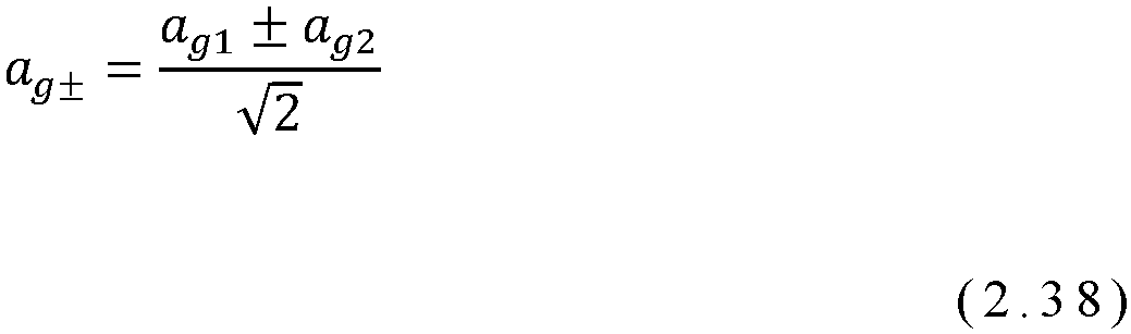
- In Equation (2.36),

- In Equation (2.37),
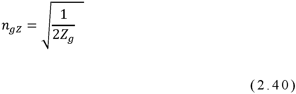
- Zg in Equations (2.39) and (2.40) is given by

- Cos(ϕ i/ϕ 0) in Equation. (2.28) is expressed in terms of creation and annihilation operators of a boson using a Tayler expansion to the fourth order, as follows.

- In Equation (2.28), with respect to the magnetic flux ϕ i that penetrates the loop of each SQUID of JPOi (i=1,2,3,4), a pump wave with an angular frequency ωp,i is applied such that the following holds.

- The function Vg in Equation (2.29) is defined by Equation (2.16) and thus contains a term cos((ϕ g1-ϕ g2)/ϕ 0), which is expanded as follows as with Equation (2.42).

- A quantized Hamiltonian is expressed by

- In Equation (2.45), HJPO,i is a Hamiltonian of each JPOi (i=1,2,3,4) and is given by,

- In Equation (2.45), Hcoupler is a Hamiltonian of the
coupler 21 and is given by the following Equation (2.47).
- In Equations (2.46) and (2.47), ω is a resonant angular frequency of the JPO corresponding to ai, ω+ and ω- are resonant angular frequencies of the
coupler 21 corresponding to ag+ and ag-, respectively. A difference in an angular frequency between different JPOs is not taken into consideration. - Htotal includes an interaction between each JPO and the
coupler 21. In Equation (2.45), g+ and g- are a strength of an interaction between each JPO and the two degrees of freedom of thecoupler 21. - In Equation (2.45),

- Since each JPO interacts with the
coupler 21, it can be assumed that JPOs are also indirectly interacted with each other through the interaction withcoupler 21. With a variable transformation to a form in which an influence of thecoupler 21 on each JPO is incorporated, an interaction betweenJPOs 1 to 4 and thecoupler 21 is transformed into a four-body interaction among JPOs. That is, it can be transformed to a Hamiltonian with a form in which JPOs are interacting directly with each other. This transformation can be expressed as a unitary transformation by the following unitary matrix U.
where ω, ω+ and ω- are resonant angular frequencies corresponding to ai, ag+ and ag- (where a frequency difference between different JPOs is not considered). g+/(ω - ω+) and g-/(ω - ω-) are assumed to be less than 1. - The above unitary transformation looks similar to one in
NPL 1, but it differs fromNPL 1 in thatNPL 1 considers only one degree of freedom of the coupler. After performing the unitary transformation, a boson of each JPO is represented by a rotated coordinate system. A frequency of rotation of the coordinate system is different for each JPO. As forJPOs 1 to 4, the coordinate system is represented by one that rotates at half the frequency of a pump signal to generate a magnetic flux penetrating the SQUID loop in each ofJPOs 1 to 4. The pump frequency is different for each JPO. A transition to the rotating coordinate system causes an oscillating term(s) to appear in the Hamiltonian in time, but the oscillating term(s) can be ignored (rotating wave approximation) because they are averaged and their positive and negative values would cancel out on a time scale of interest here. - Due to a difference in frequencies of the pump signals, many of terms representing an interaction among JPOs and an interaction between each JPO and the
coupler 21, which can oscillate and are ignored for the above reasons. By paying attention to various transformations and characteristic time scales described above, an estimation of a strength of the interaction among JPOs that occurs through thecoupler 21 is made possible. The Hamiltonian H'total obtained through the above process can be expressed as the following Equation (2.50) by focusing on the four-body interaction term.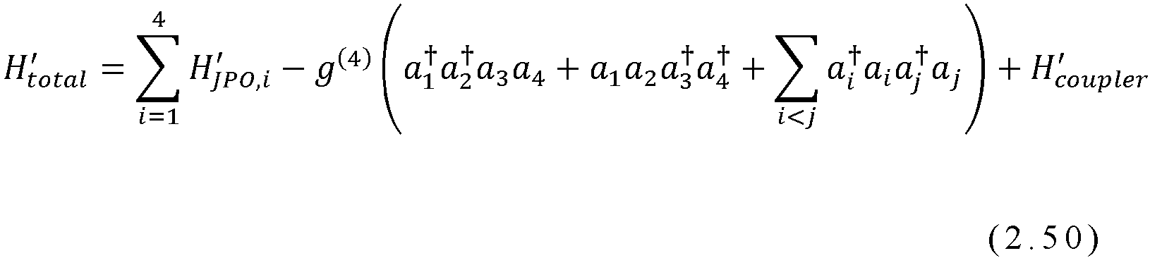
- In Equation (2.50),
- H' JPO,i (i = 1, 2, 3, 4) is each Hamiltonian of JPO1 (20A) to JPO4 (20D).
- H' coupler is a Hamiltonian of
coupler 21. - In Equation (2.50), g(4) is a coefficient (coupling coefficient) representing a strength of coupling of the four-body interaction and expressed by the following Equation (2.51), using:
- α which is a ratio of the Josephson energy of the
second Josephson junction 12 to that of thefirst Josephson junction 11 in the coupler 21 (ratio of the junction size of the Josephson junctions); - n which is a number of the
first Josephson junctions 11 connected in series in thecoupler 21; - a capacitance Cg of the
coupler 21; - a coupling capacitance C of a capacitive coupling between the
coupler 21 and each JPO; and - a resonance angular frequency ω of each JPO and a resonance angular frequency ω- of the
coupler 21. - In Equation (2.51), the resonant angular frequency ω of each JPO is given by (2.52)

- In Equation (2.52), Ec is a charging energy of the capacitance CJ of each JPO.

- EJ is a Josephson energy of the SQUID of each JPO.
- ω- is a resonant angular frequency of the coupler 21 (resonant angular frequency corresponding to the boson operator ag-) and is given by

- In Equation (2.54), E'cg is a charging energy of a composite capacitance: Cg + C and is given by

- In Equation (2.54), EJg (2) is given by Equation (2.19) and the resonant angular frequency of the
coupler 21 is given by
- The resonant angular frequency ω- of the
coupler 21 depends on n and α, while the resonant frequency ω of each JPO does not depend on n and α. - When a value of the resonant angular frequency ω- of the
coupler 21 is away from the resonant angular frequency ω of each JPO by changing n and α, the coupling coefficient g(4) of the four-body interaction becomes smaller. A value of ω- needs to be adjusted by a parameter(s) other than n and α. This can be realized by adjusting a critical current Icg of individual Josephson junctions of thecoupler 21. - The following studies a specific circuit parameter setting and shows an effect with n and α adjusted. The following setting is considered.
Frequency of JPO ω/2π 10GHz(gigaherz) Resonant frequency of coupler 21 ω - /2π9.98GHz Capacitance of each JPO CJ 1000fF(femtoFarad) Coupling capacitance of coupler 21 Cg 200fF Coupling capacitance between each JPO and coupler 21 C 1 fF - The parameters of the Josephson junction are adjusted so that the above frequencies are realized. The effect is evaluated by an absolute value of the coupling coefficient g(4) of the four-body interaction. The reason for this is as follows.
- According to Equation (2.51) regarding the coupling coefficient g(4) of the four-body interaction, the value of g(4) may be negative for some combinations of values of n and α. However, a sign of g(4) can be changed by adjusting another parameter(s) not explicitly shown here.
- Therefore, the sign of the coupling coefficient g(4) of the four-body interaction is not essential, and it is sufficient to focus only on the absolute value of g(4)
-
Fig. 7 shows a change in the absolute value of the coupling coefficient g(4) of the four-body interaction under a condition that only α is varied in the above setting for each case of n= 1, 3, 5 and 10 where n is the number of thefirst Josephson junctions 11 connected in series in thecoupler 21. InFig. 7 , a vertical axis is an absolute value of g(4) divided by h/2π and converted to MHz (megahertz) unit (h is Planck's constant (about 6.6 x 10^(-34) joule-second). The other parameters are fixed to the above set values. In particular, the resonant angular frequency ω- of thecoupler 21 is also fixed. - In
Fig. 7 , the result for n = 1 corresponds to the case of the coupler in NPL 1 (Fig. 1 in the present application). In this case, g(4) is constant regardless of α. - According to the
coupler 21 of the embodiment, n is set to 2 or more, and in a region where a value of α is large, in particular,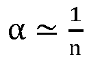
the absolute value of the coupling coefficient g(4) of the four-body interaction rapidly increases and exceeds in case of n = 1. That is, the absolute value of the coupling coefficient of the four-body interaction can be made larger than that disclosed inNPL 1. - As described above, in the above embodiment, the four-body interaction of a qubit made up of JPO is realized. In the
coupler 21, adjustment is done for n (the number offirst Josephson junctions 11 in the coupler 21) and α (a ratio of a Josephson energy of thesecond Josephson junction 12 to that of thefirst Josephson junction 1, or a ratio of a junction size of thesecond Josephson junction 12 to that of the first Josephson junction 1), where n and α are parameters included in the coupling coefficient g(4) of the four-body interaction. In particular, in the range of α = < 1/n, a change in the resonant frequency of thecoupler 21 caused by the change in α is avoided by adjusting the critical current Ic of the Josephson junction, which can enlarge the absolute value of the coupling coefficient of the four-body interaction. - The coupling coefficient g(4) of the four-body interaction in Equation. (2.51) includes a factor with respect to capacitance CJ, Cg, and C which belong to circuit parameters,

- Therefore, in addition to the circuit parameters n and α in the
coupler 21, the coupling coefficient of the four-body interaction g(4) can be enlarged by setting of the capacitance values CJ, Cg, and C. This is based on the four-body interaction coupling coefficient according to the example embodiment and is a major difference fromNPL 2 directed to a two-body interaction. - For example, by reducing the capacitance Cg of the
capacitor 15 of thecoupler 21 and the capacitance C of thecoupling capacitors 31A to 31D, Cg + C in a denominator of the coupling coefficient g(4) of the four-body interaction becomes smaller and the value of g(4) becomes larger. - Furthermore, the capacitance Cg of the
capacitor 15 of thecoupler 21 is made smaller as compared with the capacitance CJ of each JPO. - In order to realize a network for a four-body interaction which is assumed in an LHZ-scheme based quantum annealing, it is needed to weaken a two-body interaction in which only two of the four JPOs interact with each other.
- These two-body interactions are proportional to C/CJ. In the example embodiment, in order to weaken these two-body interactions, the capacitance C of the
coupling capacitors 31A to 31D between each JPO and thecoupler 21 is made smaller as compared with the capacitance CJ of each JPO, and thus CJ/C is made large. - In
Figs. 4A and4B , the configuration of the example embodiment is described as a circuit diagram. In the following, the quantum annealing device will also be described after describing an example of mounting the device on a quantum chip where a superconducting circuit(s) is/are formed in a wiring layer on a substrate. -
Fig. 8 schematically illustrates an example of a configuration of the coupler 21 (wiring pattern formed on a substrate) in a case where JPO1 (20A) to JPO4 (20D) inFig. 4A are configured as a lumped constant type. InFig. 8 , each JPO of JPO1 (20A) to JPO4 (20D) is composed of the configuration ofFig. 4A and configured as a waveguide resonator terminated to ground by each of theSQUIDs 210A to 210D. The waveguide resonator is made to oscillate in a parametric oscillation mode by modulating a magnetic flux penetrating each loop ofSQUID 210A to 210D at a frequency approximately twice the resonant frequency with each pump signal (microwave) supplied from each ofcontrol lines 23A to 23D. - In JPO1 (20A) to JPO4 (20D), the
coupler connection portions 24A to 24D extending from the conductive portions (waveguides including superconducting members) 205A to 205D connecting to the firstsuperconducting parts 203A to 203D of theSQUIDs 210A to 210D are capacitively coupled to the ends of the first and second opposingportions 17B, the third and fourth opposingportions - The
coupler connection portions 24A to 24D of JPO1 (20A) to JPO4 (20D) may, for example, include a coplanar waveguide with both sides sandwiched by a ground pattern not shown via gaps along the longitudinal direction. However, as a matter of course not limited to the above configuration. - The
coupler 21 for the four-body interaction, includes the first and second opposingportions first electrode 16 to the twoJPOs 1 and 2 (20A, 20B), respectively, and have ends faced to and capacitively coupled to, viacoupling capacitors coupler connection portions JPOs 1 and 2 (20A, 20B). Thesecond electrode 18 arranged opposing to thefirst electrode 16, includes third and fourth opposingportions coupling capacitors coupler connection portions JPOs 3 and 4 (20C and 20D). Provided between thefirst electrode 16 and thesecond electrode 18, theloop circuit 10 that includes n first Josephson junctions 11-1 to 11-n connected in series and asecond Josephson junction 12 connected in parallel to the n first Josephson junctions 11-1 to 11-n. - The ends of the first and second opposing
portions first electrode 16 and the ends of thecoupler connection portions JPOs 1 and 2 (20A and 20B), respectively opposed to the ends of the first and second opposingportions portions coupler connection portions JPOs 3 and 4 (20C and 20D) respectively opposed to the ends of the third and fourth opposingportions portions coupler connection portions portions portions coupler connection portions portions - The first and
second electrodes second electrodes second electrodes - In the example of
Fig. 8 , for simplicity, the first and second opposingportions portions second electrodes second electrodes - In the example embodiment, the
coupler 21 and JPO1 (20A) to JPO4 (20D) are realized, for example, by lines (wiring) formed by a superconductor on a substrate. The substrate is silicon (Si), but other electronic materials such as sapphire or compound semiconductor materials (Group IV, III-V, II-VI) may be used. The substrate may preferably be monocrystalline but may also be polycrystalline or amorphous. As the line material (wiring material), Nb (niobium) or Al (aluminum) may be used, for example, but is not limited thereto. Any metal that becomes a superconducting state when cooled to a very low temperature may be used, such as, niobium nitride, indium (In), lead (Pb), tin (Sn), rhenium (Re), palladium (Pd), titanium (Ti), titanium nitride, Mo (molybdenum), tantalum (Ta), tantalum nitrides, and alloys containing at least one of these, etc. In order to minimize thermal noise as much as possible, a coupler circuit is utilized in a temperature environment of about 10 mK (millikelvin), which is realized by a refrigerator. - In
Fig. 8 , the capacitance value of each capacitor may be set as
- In
Fig. 8 , when an odd number of Josephson junctions among the n first 11-1 to 11-n and thesecond Josephson junction 12 of theloop circuit 10 are π junctions, as described above, a phase difference around theloop circuit 10 is ±π × (odd number). That is, theloop circuit 10 can be biased with a magnetic flux of odd multiples of Φ0/2 (or -Φ0/2) (where Φ0 (=h/2e) is the magnetic flux quantum) without applying any external magnetic flux Φext. For this reason, thecontrol line 13 and the magneticfield generation part 14, which connect to a current control unit not shown, are not needed. -
Fig. 9A illustrates a non-limiting example of the example embodiments described above, and schematically illustrates a non-limiting example of a pattern (planar circuit) of thecoupler 21 inFig. 8 . InFig. 9A , for the sake of drawing convenience, JPO1 to JPO4 are illustrated with their respectivecoupler connection portions 24A to 24D. - Referring to
Fig. 9A , thecoupler 21 is arranged surrounded by a ground pattern (ground plane) 40. Though not limited thereto, thecoupler connection portions 24A to 24D ofJPOs 1 to 4 are surrounded on both sides by the ground pattern (ground plane) 40 via gaps, and theJPOs 1 to 4 themselves are also surrounded by the ground pattern (ground plane) 40. As shown schematically inFig. 9A , thecoupler 21 is spaced apart from an edge of the ground pattern (ground plane) 40 by a gap of about a size of the coupler 21 (on the order of a fraction to several times the size), for example. If thecoupler 21 is of the order of 10 to 100 µm (tens to hundreds of µm), a gap spacing may be approximately of this order. InFig. 9A , 41 is an area where no ground pattern is provided and the substrate is exposed. - In the non-limiting example of
FIG. 9A , a planar shape of thefirst electrode 16 is of an almost trapezoidal shape, rotated about 45 degrees counterclockwise with respect to a horizontal direction of the drawing. The first and second opposingportions first electrode 16 are extended from oblique sides (legs) of the trapezoid to the left and up in the drawing toward thecoupler connection portions second electrode 18 is an upside-down trapezoidal shape with thefirst electrode 16 rotated 180 degrees, and the third and fourth opposingportions second electrode 18 are extended from oblique sides to the right and down in the drawing toward thecoupler connection portions first electrode 16 and thesecond electrode 18 are arranged with their respective trapezoidal bottom sides facing each other, and the planar shape of the bodies together, excluding the facing portions, is close to an almost hexagonal shape. - In a vicinity of the intersection of one end of the bottom of the
first electrode 16 and the oblique side, there is provided aprotrusion 16C protruding downwardly in the figure, and in a vicinity of the intersection of one end of the bottom of thesecond electrode 18 and the oblique side, there is acut portion 18C that is cut off to be parallel to theprotrusion 16C of thefirst electrode 16. Between theprotrusion 16C in the vicinity of the intersection of one end of the lower bottom of thefirst electrode 16 and the oblique edge and thecut portion 18C in the vicinity of the intersection of one end of the lower bottom of thesecond electrode 18 and the oblique edge, theloop circuit 10 described with reference to (C) ofFig.5 is arranged (Note that due to the difference in dimensions of theloop circuit 10 andelectrodes second Josephson junction 12 are not shown in the figure). In theloop circuit 10, for example, when thesecond Josephson junction 12 is a π-junction and the remaining n first Josephson junctions 11-1 to 11-n are 0-junctions, even without providing a magnetic flux Φ0/2 penetrating theloop circuit 10, thesecond Josephson junction 12 potential energy is given by Equation (2.15), and the potential energy V(φ1) of theloop circuit 10 is the same potential energy as in Equation (2.11). - On the other hand,
Fig. 9B schematically illustrates a non-limiting example of a pattern (planar circuit) of thecoupler 21 in which in theloop circuit 10, the n first Josephson junctions 11-1 to 11-n and thesecond Josephson junction 12 are all zero junctions, and a magnetic flux Φext = Φ0/2 (Φ0 is the flux quantum = h/(2e)) penetrating theloop circuit 10 is provided from the magneticfield generation part 14. InFig. 9B , there is provided anadditional control line 13 to which a current is supplied from a current control unit not shown to generate a magnetic flux Φext penetrating theloop circuit 10. Thecontrol line 13 is configured as a line with aground pattern 40 arranged via gaps on both sides in a longitudinal direction. An end portion of thecontrol line 13 functions as the magneticfield generation part 14 inFig. 8 and is connected to ground (ground pattern 40) in a vicinity of theloop circuit 10. Therefore, adjacent to theloop circuit 10, theground pattern 40 has aregion 30 that protrudes inwardly to become closer to theloop circuit 10. DC current is supplied to thecontrol line 13 from a current control unit not shown so that the magnetic flux Φext generated by the magnetic field generation part 14 (Fig. 8 ) to penetrate theloop circuit 10 is 1/2 (= h/(4e)) of the flux quantum Φ0. - In the example illustrated in
Fig. 9B , in order to efficiently apply a magnetic flux via an inductive coupling with thecontrol line 13, out of the first andsecond electrodes loop circuit 10 including the Josephson junctions, a distance between the part of the electrode and theground pattern 40 is reduced. Thecontrol line 13 is formed in the vicinity of theloop circuit 10 and thus the magnetic flux Φext can be applied from an immediate vicinity of theloop circuit 10. As described above, theground pattern 40 is basically separated from the first andsecond electrodes Fig.9A , except for theregion 30 that is arranged closer to theloop circuit 10. InFig. 9B , thecontrol line 13 and the magneticfield generation part 14 ofFig. 8 are arranged on the same wiring layer as thecoupler 21, but the configuration is, as a matter of course, not limited to such a configuration. Thecontrol line 13 and the magneticfield generation part 14 may be provided at or near a position opposing to theloop circuit 10 of thecoupler 21, on a surface of a wiring substrate (interposer) not shown on which a quantum chip including thecoupler 21 is flip-chip mounted via bumps. - In the configuration of the
coupler 21 inFigs.9A and9B , the capacitance CJ of the capacitors of JPO1 (20A) to JPO4 (20D) (201A to 201D inFig. 4A ) , the capacitance Cg of the capacitor of the coupler 21 (15 inFig. 4A ), and the capacitance C of the coupling capacitors (31A to 31D inFig. 4A ) between thecoupler connection portions 24A to 24D and the opposingportions coupler 21, may be set as follows.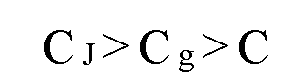
- In
NPL 2, a coupling device with a superconducting loop circuit with an array of n first Josephson junctions connected in series and a second Josephson junction connected in parallel with the array is disclosed. The following describes comparison of the disclosure of the present application with the disclosure ofNPL 2. The following points are common. - The structure of the loop circuit of the
coupler 21 is also used as a coupler structure between qubits (or photons) also inNPL 2. - A loop circuit of the Josephson junction has an array of n first Josephson junctions connected in series and one second Josephson junction connected in parallel to the array, the Josephson energy of the second Josephson junction is α times that of the first Josephson junction, and the
loop circuit 10 has an external flux Φext = h/(4e) = πϕ 0. By setting α ≈ 1/n, the interaction coefficient between the qubits can be enlarged. - There are numerous differences between the disclosure of the present application and
NPL 2. - For example, a type of interaction generated by the
coupler 21 is different. The disclosure of the present application utilizes thecoupler 21 to generate the four-body interaction of a qubit (JPO), whereasNPL 2 utilizes this coupler to generate the two-body interaction of a qubit (the four-body interaction coupler is not described at all in NPL 2). As a result, the differences are as follows. - In the embodiment, capacitors are needed to distinguish between JPO1 and JPO2, and between JPO3 and JPO4 whose connection can be done without the coupler targeted to the four-body interaction. In the example embodiments, a coupling capacitor is needed between the qubit (JPO).
- The presence or absence of this capacitor also causes the following differences.
- In the present disclosure, a resonance occurs in the
coupler 21, whereas inNPL 2, a resonance of the coupler itself cannot be conceived. Therefore, the circuit setup and ω- that appears in g(4) do not appear inNPL 2. - The devise of adjusting the value of the resonant angular frequency ω- of the coupler 21 (such that it does not change) in order to enlarge the strength of the four-body interaction (coupling coefficient) is specific to the present application.
- Furthermore, in
NPL 2, the coupler is directed to the two-body interaction, which is different from four-body interaction. Therefore, χ (quarton), etc. in Equation (7) of the coupling coefficients of the interaction inNPL 2 are completely different from the above described coupling coefficient g(4) of the four-body interaction in Equation (2.51) of the present application. - The main difference is that the disclosure of the present application is directed to the four-body interaction of qubits, whereas the
NPL 2 is directed to the two-body interaction of qubits. Due to this point, there are differences regarding presence or absence of a capacitor between the qubit and the coupler, presence or absence of resonance of the coupler, presence or absence of the need to adjust the resonant frequency of the coupler, and the expression (equation) of the interaction coefficient. - In order to enlarge the coupling coefficient of the four-body interaction in Equation (2.51), according to the present embodiment, in addition to setting the circuit parameters n and α of the
coupler 21, regarding the shunt capacitor CJ of the SQUID of each JPO, the coupling capacitance C between each JPO andcoupler 21, and the capacitance Cg of thecoupler 21, setting is done such that CJ > Cg > C. Thus, the coupling coefficient g(4) of the four-body interaction can be made large. - Furthermore, the resonant angular frequency ω of each JPO and the resonant angular frequency ω - of the
coupler 21 should not be too close. More specifically, with respect to the factor (ωω-)2/(ω - ω-)4 in Equation (2.51) of the strength of the four-body interaction,
letting

-
Fig. 10 is a schematic diagram of aquantum computer 300 in which JPOs 20 are integrated, as an example configuration of another example embodiment. In the configuration illustrated inFig. 10 , each four-body interaction coupler 21 is connected to four JPO 20s, as illustrated inFigs. 4A ,4B and8 , respectively. The unit structures illustrated inFig. 4A ,Fig. 4B ,Fig. 8 , etc. are arranged such that eachJPO 20 is connected to one to fourcouplers 21 for a four-body interaction, andJPO 20 is shared and arranged by multiple unit structures. In thequantum computer 300, at least oneJPO 20 is connected to a plurality ofcouplers 21 for a four-body interaction. In particular, in the example illustrated inFig. 10 , at least oneJPO 20 is connected to fourcouplers 21 for a four-body interaction. Thequantum computer 300 may also be described as follows. Thequantum computer 300 has a plurality of JPOs 20, eachJPO 20 being connected to one to fourcouplers 21 for a four-body interaction. The number ofcouplers 21 for a four-body interaction to which eachJPO 20 is connected corresponds to how many of theJPOs 20 are shared in the unit structure. Thus, in the example illustrated inFig. 10 , thequantum computer 300 has multiple unit structures and theJPO 20 is shared by multiple unit structures. In the example illustrated inFig. 10 , 13 superconductingnonlinear JPOs 20 are integrated, but any number ofJPOs 20 can be integrated in a similar manner. InFig. 10 , a current control part and a readout part are omitted for ease of understanding of the drawing, butJPO 20 is controlled and read out using a current control part and a readout part as described with reference toFig. 3 . - The disclosure of the above embodiments may be annexed as follows (but, as a matter of course, not limited to the following).
- A superconducting quantum circuit includes first through fourth qubits and a coupler that couples the first through fourth qubits by a four-body interaction. The coupler includes a loop circuit connected between one end and an other end of the coupler; a capacitor connected in parallel to the loop circuit.
- The loop circuit includes n (n is a positive integer greater than or equal to 2) first Josephson junctions spaced apart from each other and arranged in series, and n (n is a positive integer greater than or equal to 2); a second Josephson junction arranged in parallel with the n first Josephson junctions and having a junction size smaller than that of the first Josephson junction.
- The first and second qubits are capacitively coupled to the one end of the coupler, respectively and the third and fourth qubits are capacitively coupled to the other end of the coupler, respectively.
- A magnitude of the coupling coefficient of the four-body interaction by the coupler is set based on circuit parameters including at least n and α (0 < α< 1) which is a ratio of a Josephson energy of the second Josephson junction and that of the first Josephson junction.
- The superconducting quantum circuit according to
Note 1, wherein in the coupler, the α may be set to a predetermined value close to 1/n within a range smaller than 1/n which is an inverse of n. - The loop circuit may be biased with a magnetic flux ±Φ0/2× (2k+1) (where Φ0 (=h/(2e)) is a magnetic flux quantum: h is a Planck's constant and e is an elementary charge). The superconducting quantum circuit according to
Note - In the superconducting quantum circuit according to
Note - In the superconducting quantum circuit device according to any one of
Notes 1 to 4, wherein the loop circuit of the coupler has a first electrode and a second electrode arranged opposite each other spaced apart from a ground pattern in an area surrounded by the ground pattern in a wiring layer on a substrate. The n (n being two or more positive integers) first Josephson junctions and the second Josephson junction, and are arranged in parallel between the first electrode and the second electrode, respectively. - The first electrode may include first and second opposing portions extended towards the first and second qubits from locations of the first electrode other than a side of the first electrode faced to the second electrode, respectively, the first and second opposing portions having ends capacitively coupled to ends of coupler connection portions of the first and second qubits, respectively.
- The second electrode may include third and fourth opposing portions extended towards the third and fourth qubits from locations of the second electrode other than a side of the second electrode faced to the first electrode, respectively, the third and fourth opposing portions having ends capacitively coupled to ends of coupler connection portions of the third and fourth qubits, respectively.
- In the superconducting quantum circuit according to
Note 5, each of the first and fourth qubits includes a Josephson parametric oscillator, wherein the Josephson parametric oscillator includes - a superconducting quantum interference device (SQUID) including two Josephson junctions at both ends where a first superconducting line and a second superconducting line that constitute a loop intersect;
- a capacitor connected in parallel to the SQUID; and
- a line that is inductively coupled to the SQUID to generate a magnetic flux that penetrates the loop of the SQUID, wherein one of the first and second superconducting lines of the SQUID is set to a ground potential, and the other of the first and second superconducting lines of the SQUID is connected to the coupler connection portion and the SQUID may be configured to oscillate parametrically according to the microwave current supplied to the line.
- In the superconducting quantum circuit according to Note 6, the circuit parameter defining the coupling coefficient of the four-body interaction includes, in addition to the α and the n,
- C, a value of capacitance of the capacitive coupling between the coupler connection portion of each of the first to fourth qubits and each of the first to fourth opposing portions of the coupler;
- CJ, a value of capacitance of the capacitor connected in parallel to the SQUID of each of the first and fourth qubits; and,
- Cg, a value of capacitance between the first and second electrodes of the coupler,
- with a magnitude relationship thereamong set to

- In the superconducting quantum circuit according to Note 6 or 7, with respect to circuit parameters including
- the α and the n;
- C, a value of the capacitance of the capacitive coupling between the coupler connection portion of each of the first and fourth qubits and each of the first and fourth opposing portions of the coupler;
- CJ, a value of the capacitance of the capacitors connected in parallel to the loop circuit of each of the first and fourth qubits; ,
- Cg, a value of the capacitance between the first and second electrodes of the coupler, and
- a difference between a resonant angular frequency ω- of the coupler and a resonant angular frequency ω of each qubit,
- the coupling coefficient of the four-body interaction may be configured to be expressed as follows.

- A superconducting quantum circuit apparatus, wherein the superconducting quantum circuit according to any one of
Notes 1 to 8, constitute a quantum computer that includes, as a unit structure, the first to fourth qubits that perform Josephson parametric oscillation; and the coupler. - The superconducting quantum circuit apparatus as according to Note 9, wherein a plurality of the unit structures are provided, and the unit structure may constitute a quantum computer in which at least one of the first through fourth qubits are shared by one or more other the unit structures.
- Each disclosure of
PTLs NPLs 1 to 5 cited above is incorporated herein in its entirety by reference thereto. It is to be noted that it is possible to modify or adjust the example embodiments or examples within the whole disclosure of the present invention (including the Claims) and based on the basic technical concepts thereof. Further, it is possible to variously combine or select a wide variety of the disclosed elements (including the individual elements of the individual claims, the individual elements of the individual examples and the individual elements of the individual figures) within the scope of the Claims of the present invention. That is, it is self-explanatory that the present invention includes any types of variations and modifications to be done by a skilled person according to the whole disclosure including the Claims, and the technical concept thereof. -
- 1 Superconducting quantum circuit
- 10 Loop circuit (nonlinear element)
- 11, 11-1 to 11-n First Josephson junction
- 12 Second Josephson junction
- 13 Control line
- 14 Magnetic field generation part
- 15 Capacitor
- 16 Electrode (first electrode)
- 16C Protrusions
- 17A, 17B First and second opposing portions
- 18 Electrode (second electrode)
- 19A, 19B Third and fourth opposing portion
- 20A-20D, 120A-120D Superconducting qubit (JPO)
- 21, 121 Coupler
- 122A-122D Readout circuit connections
- 23A-23D, 123A-123D Control lines (flux lines)
- 24A to 24D, 124A-124D Coupler connections
- 30 Part (ground pattern overhang)
- 31A to 31D Capacitor (coupling capacitor)
- 40 Ground (GND) pattern (ground plane)
- 41 Substrate surface
- 101-1 to 101-n Superconducting lines
- 102-1, 102-2 Superconducting lines
- 103, 104 Superconducting lines
- 110 Non-linear elements
- 132A-132D Capacitors
- 140A-140D Readout circuits
- 150A to 150D Signal generation section
- 201A, 201B, 201C, 201D First Josephson junction
- 202A, 202B, 202C, 202D Second Josephson junction
- 203A, 203B, 203C, 203D First superconducting section
- 204A, 204B, 204C, 204D Second superconducting section
- 205A, 205B, 205C, 205D Conducting part
- 206A, 206B, 206C, 206D Capacitor
- 207A, 207B, 207C, 207D Magnetic field generation part
- 300 Quantum computer

Claims (10)
- A superconducting quantum circuit comprising:first to fourth qubits; anda coupler that couples the first to fourth qubits by a four-body interaction,wherein the coupler includes:a loop circuit connected between one end and an other end of the coupler; anda capacitor connected in parallel to the loop circuit,wherein the loop circuit includes:n (n is a positive integer greater than or equal to 2) first Josephson junctions spaced apart from each other and arranged in series; anda second Josephson junction arranged in parallel with the n first Josephson junctions, the second Josephson junction having a junction size smaller than that of the first Josephson junction,wherein the first and second qubits are capacitively coupled to the one end of the coupler, respectively, andthe third and fourth qubits are capacitively coupled to the other end of the coupler, respectively, andwherein a magnitude of a coupling coefficient of the four-body interaction by the coupler is made configurable based on circuit parameters including at least the n; andα (0<α<1) that is a ratio of a Josephson energy of the second Josephson junction and that of the first Josephson junction.
- The superconducting quantum circuit according to claim 1, wherein in the coupler, the α is set to a predetermined value close to 1/n within a range smaller than 1/n an inverse of the n.
- The superconducting quantum circuit according to claim 1 or 2, comprisinga magnetic field generation part,wherein the magnetic field generation part, when a DC current from a current control part is passed therethrough, generates a magnetic flux Φ0/2 or - Φ0/2 (where Φ0 (=h/(2e)) is a magnetic flux quantum: h is a Planck's constant and e is an elementary charge), the magnetic flux penetrating the loop circuit of the coupler.
- The superconducting quantum circuit according to claim 1 or 2, wherein, out of the n first Josephson junctions and the second Josephson junction of the loop circuit,odd number (2k+1, where k is a predetermined non-negative integer) junctions are set to π-junctions and rest are set to zero-junctions, anda phase difference when going around the loop circuit is ±π × (2k+1),the loop circuit being in a state biased with a magnetic flux ± Φ0/2 × (2k+1) (where Φ0 (=h/(2e)) is a magnetic flux quantum: h is a Planck's constant and e is an elementary charge) without applying any magnetic flux that penetrates the loop circuit.
- The superconducting quantum circuit device according to any one of claims 1 to 4, wherein the loop circuit of the coupler includesa first electrode and a second electrode arranged opposite to each other, and spaced apart from a ground pattern in a region surrounded by the ground pattern in a wiring layer on a substrate,wherein the n (n being two or more positive integers) first Josephson junctions and the second Josephson junction are arranged in parallel between the first electrode and the second electrode, respectively,wherein the first electrode includesfirst and second opposing portions extended towards the first and second qubits from locations of the first electrode different from a side where the first electrode is opposed to the second electrode, respectively, the first and second opposing portions having ends capacitively coupled to ends of coupler connection portions of the first and second qubits, respectively, andwherein the second electrode includesthird and fourth opposing portions extended towards the third and fourth qubits from locations of the second electrode different from a side where the second electrode is opposed to the first electrode, respectively, the third and fourth opposing portions having ends capacitively coupled to ends of coupler connection portions of the third and fourth qubits, respectively.
- The superconducting quantum circuit according to claim 5, where each of the first to fourth qubits includesa Josephson parametric oscillator,wherein the Josephson parametric oscillator includes:a superconducting quantum interference device (SQUID) includingtwo Josephson junctions at both ends where a first superconducting line and a second superconducting line that constitute a loop intersect;a capacitor connected in parallel to the SQUID; anda line configured to inductively couple to the SQUID to generate a magnetic flux that penetrates the loop of the SQUID,wherein one of the first and second superconducting lines of the SQUID is set to a ground potential, andan other of the first and second superconducting lines of the SQUID is connected to the coupler connection portion, andwherein the Josephson parametric oscillator is configured to perform parametric oscillation according to a microwave current supplied to the line.
- The superconducting quantum circuit according to claim 6, wherein circuit parameter defining the coupling coefficient of the four-body interaction includes, in addition to the α and the n,C which is a value of capacitance of a capacitive coupling between the coupler connection portion of each of the first to fourth qubits and each of the first to fourth opposing portions of the coupler;CJ which is a value of capacitance of the capacitor connected in parallel to the SQUID of each of the first and fourth qubits; and,Cg which is a value of capacitance between the first and second electrodes of the coupler, with a magnitude relationship thereamong set to CJ>Cg>C.
- The superconducting quantum circuit according to claim 6 or 7, wherein with respect to circuit parameters including:the α and the n;C which is a value of the capacitance of the capacitive coupling between the coupler connection portion of each of the first and fourth qubits and each of the first and fourth opposing portions of the coupler;CJ which is a value of the capacitance of the capacitors connected in parallel to the loop circuit of each of the first and fourth qubits;Cg which is a value of the capacitance between the first and second electrodes of the coupler; anda difference between a resonant angular frequency ω- of the coupler and a resonant angular frequency ω of each qubit,the coupling coefficient of the four-body interaction is given by

- A superconducting quantum circuit apparatus including the superconducting quantum circuit according to any one of claims 1 to 8, that constitutes a quantum computer including, as a unit structure, the first to fourth qubits that are each configured to perform Josephson parametric oscillation and the coupler.
- The superconducting quantum circuit apparatus as according to claim 9, including a plurality of the unit structures, wherein the unit structure constitutes a quantum computer in which at least one of the first through fourth qubits are shared by one or more other the unit structures.
Applications Claiming Priority (1)
| Application Number | Priority Date | Filing Date | Title |
|---|---|---|---|
| PCT/JP2022/024825 WO2023248370A1 (en) | 2022-06-22 | 2022-06-22 | Superconducting quantum circuit |
Publications (2)
| Publication Number | Publication Date |
|---|---|
| EP4546999A1 true EP4546999A1 (en) | 2025-04-30 |
| EP4546999A4 EP4546999A4 (en) | 2025-08-20 |
Family
ID=89379619
Family Applications (1)
| Application Number | Title | Priority Date | Filing Date |
|---|---|---|---|
| EP22947932.4A Pending EP4546999A4 (en) | 2022-06-22 | 2022-06-22 | SUPERCONDUCTING QUANTUM CIRCUIT |
Country Status (4)
| Country | Link |
|---|---|
| US (1) | US20250328799A1 (en) |
| EP (1) | EP4546999A4 (en) |
| JP (1) | JPWO2023248370A1 (en) |
| WO (1) | WO2023248370A1 (en) |
Families Citing this family (1)
| Publication number | Priority date | Publication date | Assignee | Title |
|---|---|---|---|---|
| WO2024023176A1 (en) * | 2022-07-27 | 2024-02-01 | Socpra Sciences Et Génie S.E.C. | Method of operating a quantum system |
Family Cites Families (10)
| Publication number | Priority date | Publication date | Assignee | Title |
|---|---|---|---|---|
| ES2850151T3 (en) | 2015-06-29 | 2021-08-25 | Parity Quantum Computing GmbH | Quantum processing device and procedure |
| US9843312B2 (en) * | 2015-09-30 | 2017-12-12 | International Business Machines Corporation | Multimode Josephson parametric converter: coupling Josephson ring modulator to metamaterial |
| US9929978B2 (en) * | 2015-10-07 | 2018-03-27 | Northrop Grumman Systems Corporation | Superconducting cross-bar switch system |
| CA2968830C (en) * | 2017-05-29 | 2024-04-02 | Socpra Sciences Et Genie S.E.C. | Quantum processor, and method of quantum processing |
| US10398031B2 (en) * | 2017-09-29 | 2019-08-27 | International Business Machines Corporation | Integrating Josephson amplifiers or Josephson mixers into printed circuit boards |
| JP7279792B2 (en) * | 2019-07-19 | 2023-05-23 | 日本電気株式会社 | Resonators, Oscillators, and Quantum Computers |
| WO2021014885A1 (en) * | 2019-07-19 | 2021-01-28 | 日本電気株式会社 | Resonator, oscillator, and quantum computer |
| JP7351338B2 (en) * | 2019-07-19 | 2023-09-27 | 日本電気株式会社 | Superconducting circuits and quantum computers |
| US11615336B2 (en) * | 2020-03-02 | 2023-03-28 | Massachusetts Institute Of Technology | Cancellation of unwanted interactions in a superconducting quantum architecture |
| EP4128081A4 (en) * | 2020-03-27 | 2024-04-24 | D-Wave Systems Inc. | Systems and methods for scalable quantum computing |
-
2022
- 2022-06-22 JP JP2024528164A patent/JPWO2023248370A1/ja active Pending
- 2022-06-22 WO PCT/JP2022/024825 patent/WO2023248370A1/en not_active Ceased
- 2022-06-22 EP EP22947932.4A patent/EP4546999A4/en active Pending
- 2022-06-22 US US18/872,941 patent/US20250328799A1/en active Pending
Also Published As
| Publication number | Publication date |
|---|---|
| WO2023248370A1 (en) | 2023-12-28 |
| US20250328799A1 (en) | 2025-10-23 |
| EP4546999A4 (en) | 2025-08-20 |
| JPWO2023248370A1 (en) | 2023-12-28 |
Similar Documents
| Publication | Publication Date | Title |
|---|---|---|
| US10847705B2 (en) | Reducing crosstalk from flux bias lines in qubit devices | |
| US12063035B2 (en) | Superconducting quantum circuit apparatus and control method for a super conducting quantum circuit | |
| US10319896B2 (en) | Shielded interconnects | |
| US7369093B2 (en) | Superconducting quantum antenna | |
| US11494682B2 (en) | Quantum computing assemblies | |
| US10042805B2 (en) | Tunable bus-mediated coupling between remote qubits | |
| EP3262697B1 (en) | Techniques for producing quantum amplifiers and related systems and methods | |
| US8975912B2 (en) | Multi-tunable superconducting circuits | |
| Zorin et al. | Traveling-wave parametric amplifier based on three-wave mixing in a Josephson metamaterial | |
| US20200265334A1 (en) | Improved qubit designs for quantum circuits | |
| US10819281B2 (en) | Electronic circuit, oscillator, and calculating device | |
| WO2019004991A1 (en) | Quantum computing assemblies | |
| US12188999B2 (en) | Superconducting quantum circuit | |
| US20250007462A1 (en) | Oscillation apparatus, quantum computer, and control method | |
| US10553775B2 (en) | Electronic circuit, oscillator, quantum bit, and computing device | |
| JP7578157B2 (en) | Resonators, oscillators, and quantum computers | |
| US12244306B2 (en) | Superconducting quantum circuit | |
| US10998891B2 (en) | Frequency converter based on non-linear transmission line including dispersion control elements | |
| CN112385140A (en) | Superconducting device mixing surface acoustic wave and microwave signals | |
| US20220263467A1 (en) | Oscillation apparatus, quantum computer, and control method | |
| EP4546999A1 (en) | Superconducting quantum circuit | |
| EP4682778A1 (en) | Non-linear superconducting quantum circuit | |
| US20250272590A1 (en) | Superconducting quantum circuit apparatus | |
| US20250131306A1 (en) | Non-Galvanic and Differential Coupling of Quantum Bit Chips | |
| US20230318601A1 (en) | Superconducting quantum circuit apparatus |
Legal Events
| Date | Code | Title | Description |
|---|---|---|---|
| STAA | Information on the status of an ep patent application or granted ep patent |
Free format text: STATUS: THE INTERNATIONAL PUBLICATION HAS BEEN MADE |
|
| PUAI | Public reference made under article 153(3) epc to a published international application that has entered the european phase |
Free format text: ORIGINAL CODE: 0009012 |
|
| STAA | Information on the status of an ep patent application or granted ep patent |
Free format text: STATUS: REQUEST FOR EXAMINATION WAS MADE |
|
| 17P | Request for examination filed |
Effective date: 20250118 |
|
| AK | Designated contracting states |
Kind code of ref document: A1 Designated state(s): AL AT BE BG CH CY CZ DE DK EE ES FI FR GB GR HR HU IE IS IT LI LT LU LV MC MK MT NL NO PL PT RO RS SE SI SK SM TR |
|
| REG | Reference to a national code |
Ref country code: DE Ref legal event code: R079 Free format text: PREVIOUS MAIN CLASS: H10N0060120000 Ipc: G06N0010400000 |
|
| A4 | Supplementary search report drawn up and despatched |
Effective date: 20250721 |
|
| RIC1 | Information provided on ipc code assigned before grant |
Ipc: G06N 10/40 20220101AFI20250715BHEP Ipc: H10N 60/12 20230101ALI20250715BHEP Ipc: G06F 7/38 20060101ALI20250715BHEP |
|
| DAV | Request for validation of the european patent (deleted) | ||
| DAX | Request for extension of the european patent (deleted) | ||
| GRAP | Despatch of communication of intention to grant a patent |
Free format text: ORIGINAL CODE: EPIDOSNIGR1 |
|
| STAA | Information on the status of an ep patent application or granted ep patent |
Free format text: STATUS: GRANT OF PATENT IS INTENDED |
|
| INTG | Intention to grant announced |
Effective date: 20260210 |
|
| GRAS | Grant fee paid |
Free format text: ORIGINAL CODE: EPIDOSNIGR3 |