EP4546961A1 - Fixed structure and electronic apparatus - Google Patents
Fixed structure and electronic apparatus Download PDFInfo
- Publication number
- EP4546961A1 EP4546961A1 EP24189115.9A EP24189115A EP4546961A1 EP 4546961 A1 EP4546961 A1 EP 4546961A1 EP 24189115 A EP24189115 A EP 24189115A EP 4546961 A1 EP4546961 A1 EP 4546961A1
- Authority
- EP
- European Patent Office
- Prior art keywords
- fixed structure
- region
- electronic module
- mainboard
- supporting base
- Prior art date
- Legal status (The legal status is an assumption and is not a legal conclusion. Google has not performed a legal analysis and makes no representation as to the accuracy of the status listed.)
- Pending
Links
Images

Classifications
-
- H—ELECTRICITY
- H05—ELECTRIC TECHNIQUES NOT OTHERWISE PROVIDED FOR
- H05K—PRINTED CIRCUITS; CASINGS OR CONSTRUCTIONAL DETAILS OF ELECTRIC APPARATUS; MANUFACTURE OF ASSEMBLAGES OF ELECTRICAL COMPONENTS
- H05K7/00—Constructional details common to different types of electric apparatus
- H05K7/14—Mounting supporting structure in casing or on frame or rack
- H05K7/1401—Mounting supporting structure in casing or on frame or rack comprising clamping or extracting means
- H05K7/1402—Mounting supporting structure in casing or on frame or rack comprising clamping or extracting means for securing or extracting printed circuit boards
- H05K7/1405—Mounting supporting structure in casing or on frame or rack comprising clamping or extracting means for securing or extracting printed circuit boards by clips or resilient members, e.g. hooks
-
- H—ELECTRICITY
- H05—ELECTRIC TECHNIQUES NOT OTHERWISE PROVIDED FOR
- H05K—PRINTED CIRCUITS; CASINGS OR CONSTRUCTIONAL DETAILS OF ELECTRIC APPARATUS; MANUFACTURE OF ASSEMBLAGES OF ELECTRICAL COMPONENTS
- H05K7/00—Constructional details common to different types of electric apparatus
- H05K7/02—Arrangements of circuit components or wiring on supporting structure
- H05K7/12—Resilient or clamping means for holding component to structure
-
- H—ELECTRICITY
- H05—ELECTRIC TECHNIQUES NOT OTHERWISE PROVIDED FOR
- H05K—PRINTED CIRCUITS; CASINGS OR CONSTRUCTIONAL DETAILS OF ELECTRIC APPARATUS; MANUFACTURE OF ASSEMBLAGES OF ELECTRICAL COMPONENTS
- H05K1/00—Printed circuits
- H05K1/18—Printed circuits structurally associated with non-printed electric components
- H05K1/182—Printed circuits structurally associated with non-printed electric components associated with components mounted in printed circuit boards [PCB], e.g. insert-mounted components [IMC]
- H05K1/183—Printed circuits structurally associated with non-printed electric components associated with components mounted in printed circuit boards [PCB], e.g. insert-mounted components [IMC] associated with components mounted in and supported by recessed areas of the PCBs
-
- H—ELECTRICITY
- H05—ELECTRIC TECHNIQUES NOT OTHERWISE PROVIDED FOR
- H05K—PRINTED CIRCUITS; CASINGS OR CONSTRUCTIONAL DETAILS OF ELECTRIC APPARATUS; MANUFACTURE OF ASSEMBLAGES OF ELECTRICAL COMPONENTS
- H05K1/00—Printed circuits
- H05K1/02—Details
-
- H—ELECTRICITY
- H05—ELECTRIC TECHNIQUES NOT OTHERWISE PROVIDED FOR
- H05K—PRINTED CIRCUITS; CASINGS OR CONSTRUCTIONAL DETAILS OF ELECTRIC APPARATUS; MANUFACTURE OF ASSEMBLAGES OF ELECTRICAL COMPONENTS
- H05K7/00—Constructional details common to different types of electric apparatus
- H05K7/02—Arrangements of circuit components or wiring on supporting structure
- H05K7/10—Plug-in assemblages of components, e.g. IC sockets
-
- H—ELECTRICITY
- H05—ELECTRIC TECHNIQUES NOT OTHERWISE PROVIDED FOR
- H05K—PRINTED CIRCUITS; CASINGS OR CONSTRUCTIONAL DETAILS OF ELECTRIC APPARATUS; MANUFACTURE OF ASSEMBLAGES OF ELECTRICAL COMPONENTS
- H05K2201/00—Indexing scheme relating to printed circuits covered by H05K1/00
- H05K2201/10—Details of components or other objects attached to or integrated in a printed circuit board
- H05K2201/10431—Details of mounted components
- H05K2201/10568—Integral adaptations of a component or an auxiliary PCB for mounting, e.g. integral spacer element
-
- H—ELECTRICITY
- H05—ELECTRIC TECHNIQUES NOT OTHERWISE PROVIDED FOR
- H05K—PRINTED CIRCUITS; CASINGS OR CONSTRUCTIONAL DETAILS OF ELECTRIC APPARATUS; MANUFACTURE OF ASSEMBLAGES OF ELECTRICAL COMPONENTS
- H05K2201/00—Indexing scheme relating to printed circuits covered by H05K1/00
- H05K2201/10—Details of components or other objects attached to or integrated in a printed circuit board
- H05K2201/10431—Details of mounted components
- H05K2201/10598—Means for fastening a component, a casing or a heat sink whereby a pressure is exerted on the component towards the PCB
Definitions
- the present invention relates to a fixed structure, and in particular to a fixed structure configured to fix an electronic module to a mainboard of an electronic apparatus and an electronic apparatus including such fixed structure.
- the present invention provides a fixed structure and an electronic apparatus.
- the fixed structure can be used to fix the electronic module to the mainboard without screws, and the fixed structure can be adjusted based on requirements to fix electronic modules in at least two different sizes.
- the fixed structure provided by the present invention is suitable for fixing an electronic module to a mainboard, and the mainboard is provided with an insertion slot.
- the electronic module has a first end and a second end opposite to each other, the first end is connected to the insertion slot, and an interval space is present between the electronic module and the mainboard.
- the fixed structure includes a supporting base and a movable base.
- the supporting base includes a top, and the top is at least predefined with a first region and a second region.
- the movable base includes a positioning body and an elastic clamping portion.
- the elastic clamping portion is connected to the positioning body, and the positioning body is disposed in the first region or the second region of the supporting base.
- the supporting base is opposite to the insertion slot, part of the supporting base and part of the positioning body disposed thereon are accommodated in the interval space to support part of the electronic module, and the elastic clamping portion is suitable for clamping the second end of the electronic module.
- the top of the supporting base is provided with a fixed hole
- the fixed structure further includes a fastener, and the fastener passes through the fixed holes to fix the supporting base on the mainboard.
- the fixed hole is of a countersunk hole structure
- the fastener is a countersunk screw
- the positioning body of the movable base includes a main body, two side portions, and a plurality of clamped portions.
- the main body has a front edge, a rear edge, and two side edges opposite to each other.
- the front edge is opposite to the rear edge, the two side portions are respectively disposed on the two side edges, and each side portion is connected to two clamped portions.
- the supporting base further includes two side plates respectively connected to two opposite sides of the top, and each side plate is configured with a first clamping groove, a second clamping groove, and a third clamping groove that are spaced apart, wherein the second clamping groove is between the first clamping groove and the third clamping groove.
- the elastic clamping portion of the movable base includes an elastic arm, a connecting portion, and an abutting portion.
- One end of the elastic arm is connected to the rear edge of the main body, and the other end of the elastic arm is connected to one side of the connecting portion.
- the connecting portion is opposite to the main body, the abutting portion is connected to an opposite side of the connecting portion away from the elastic arm, and the abutting portion is suitable for being abutting against the electronic module.
- the movable base further includes a stop pillar, the stop pillar is disposed on the main body and adjacent to the abutting portion, the second end of the electronic module is provided with a notch, and the stop pillar corresponds to the notch.
- a first accommodation length is present from the stop pillar to the insertion slot
- a second accommodation length is present from the stop pillar to the insertion slot, wherein the first accommodation length is smaller than the second accommodation length
- part of the first region overlaps part of the second region.
- the mainboard includes a first block and a second block apart from each other, the insertion slot is disposed in the first block, and the fixed structure is disposed in the second block.
- the electronic apparatus includes a mainboard, an electronic module, and the foregoing fixed structure.
- the mainboard is provided with an insertion slot.
- the electronic module has a first end and a second end opposite to each other, the first end is connected to the insertion slot, and an interval space is present between the electronic module and the mainboard.
- the fixed structure fixes the electronic module to the mainboard.
- the fixed structure includes a supporting base and a movable base.
- the supporting base includes a top and side plates, and the top is at least predefined with a first region and a second region.
- the movable base includes a positioning body and an elastic clamping portion.
- the elastic clamping portion is connected to the positioning body, and the positioning body is disposed in the first region or the second region of the supporting base.
- the supporting base is opposite to the insertion slot, part of the supporting base and part of the positioning body disposed thereon are accommodated in the interval space to support part of the electronic module, and the elastic clamping portion is suitable for clamping the second end
- the elastic clamping portion is formed on the movable base, and the movable base is movable with respect to the supporting base, different accommodation lengths can be present between the movable base and the insertion slots of the mainboard, and thus are suitable for fixing electronic modules in different sizes.
- the elastic clamping portion clamps one end of the electronic module.
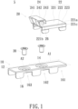
- FIG. 1 is a schematic exploded diagram of a fixed structure according to an embodiment of the present invention.
- a fixed structure 5 includes a supporting base 10 and a movable base 20.
- the supporting base 10 includes a top 12 and two opposite side plates 16.
- the two opposite side plates 16 are respectively connected to two opposite sides of the top 12, and the top 12 is predefined with a first region A1 and a second region A2.
- the movable base 20 includes a positioning body 22 and an elastic clamping portion 24, and the elastic clamping portion 24 is connected to the positioning body 22.
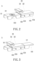
- FIG. 2 is a schematic three-dimensional diagram in which a movable base of a fixed structure is located in a first region of a supporting base according to an embodiment of the present invention.
- FIG. 1 is a schematic exploded diagram of a fixed structure according to an embodiment of the present invention.
- FIG. 3 is a schematic three-dimensional diagram in which a movable base of a fixed structure is located in a second region of a supporting base according to an embodiment of the present invention.
- the positioning body 22 of the movable base 20 can be detachably disposed in the first region A1 (shown in FIG. 1 ) or the second region A2 (shown in FIG. 1 ) of the supporting base 10 based on requirements.
- the positioning body 22 of the movable base 20 includes a main body 221, two opposite side portions 222, and a plurality of clamped portions 223.
- the main body 221 has a front edge 221a, a rear edge 221b, and two opposite side edges 221c, and the front edge 221a is opposite to the rear edge 221b.
- the two opposite side portions 222 are respectively connected to two side edges 221c of the main body 221.
- four clamped portions 223 are provided, of which, two and two are respectively connected to two side portions 222. That is, each side portion 222 is connected to two clamped portions 223.
- the elastic clamping portion 24 of the movable base 20 is connected to the positioning body 22.
- the elastic clamping portion 24 includes an elastic arm 241, a connecting portion 242, and an abutting portion 243.
- One end of the elastic arm 241 is connected to the rear edge 221b of the main body 221, and the other end of the elastic arm 241 is connected to a side of the connecting portion 242.
- the connecting portion 242 is opposite to the main body 221.
- the abutting portion 243 is connected to an opposite side of the connecting portion 242 away from the elastic arm 241.
- two elastic arms 241 and two abutting portions 243 are provided, which is not limited thereto.
- the movable base 20 further includes a stop pillar 26, and the stop pillar 26 is disposed on the main body 221 and adjacent to the abutting portion 243 and the rear edge 221b of the main body 221, which is not limited thereto.
- the two side plates 16 of the supporting base 10 are each provided with a first clamping groove 161, a second clamping groove 162, and a third clamping groove 163 that are spaced apart, wherein the second clamping groove 162 is between the first clamping groove 161 and the third clamping groove 163.
- FIG. 2 when the clamped portions 223 of the movable base 20 are clamped at the first clamping grooves 161 and the second clamping grooves 162, and the main body 221 of the movable base 20 is located in the first region A1.
- the first region A1 and the second region A2 of the supporting base 10 partially overlap, that is, the first region A1 and the second region A2 both cover the top 12 corresponding to the second clamping groove 162.
- the supporting base 10 is made of, for example, stainless steel.
- the movable base 20 is made of, for example, soft metal plate, which is elastic and allows the side portion 222 and the clamped portion 223 to be deformable, so as to be clamped with the side plate 16 (or the clamping grooves) of the supporting base 10, and the movable base 20 can be easily detached from the supporting base 10 to be readjusted and assembled in a different position of the top 12 of the supporting base 10.
- the top 12 of the supporting base 10 is provided with a fixed hole 14, and the fixed structure 5 further includes a fastener 30.
- the fastener 30 passing through the fixed hole 14 and the mainboard 2 as described later, the supporting base 10 can be fixed on the mainboard 2.
- the fixed hole 14 is of, for example, a countersunk hole structure
- the fastener 30 is, for example, a countersunk screw.
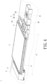
- FIG. 4 is a schematic diagram of an application state of a fixed structure according to an embodiment of the present invention.
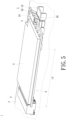
- FIG. 5 is a schematic diagram of another application state of a fixed structure according to an embodiment of the present invention.
- FIG. 4 shows the application state of the movable base 20 of the fixed structure 5 being in the first region A1 (shown in FIG. 1 ) of the supporting base 10
- FIG. 5 is an application state of the movable base 20 of the fixed structure 5 being in the second region A2 (shown in FIG. 1 ) of the supporting base 10.
- the fixed structure 5 is suitable for fixing an electronic module 4 in a different size on the mainboard 2 of the electronic apparatus 1.
- FIG. 4 shows the application state of the movable base 20 of the fixed structure 5 being in the first region A1 (shown in FIG. 1 ) of the supporting base 10
- FIG. 5 is an application state of the movable base 20 of the fixed structure 5 being in the second region A2 (shown in FIG. 1 ) of the supporting base 10.
- the electronic apparatus 1 includes a mainboard 2, an electronic module 4, and a fixed structure 5.
- the mainboard 2 is provided with an insertion slot 3
- the supporting base 10 of the fixed structure 5 is suitable for being disposed opposite to the insertion slot 3
- the mainboard 2 is provided with, for example, a stud 31.
- the supporting base 10 is fixed on the mainboard 2 by the fastener 30 passing through the fixed holes 14 and the studs 31.
- the electronic module 4 has a first end 41 and a second end 42 opposite to each other, the first end 41 is electrically connected to the insertion slot 3, and the second end 42 is disposed on the movable base 20 of the fixed structure 5 to be clamped by the elastic clamping portion 24.
- an interval space S is present between the electronic module 4 and the mainboard 2, and part of the supporting base 10 and part of the movable base 20 disposed thereon are accommodated in the interval space S to support part of the electronic module 4, and the elastic clamping portion 24 clamps the second end 42 of the electronic module 4.
- the second end 42 of the electronic module 4 is provided with a notch G, and the shape of the notch G can correspond to a partial contour of the stop pillar 26 of the movable base 20.
- the notch G is engaged with the stop pillar 26, such that the electronic module 4 does not fall off easily, thus enhancing the positioning effect of the electronic module 4.
- the electronic apparatus 1 is, for example, a laptop, a tablet, or a monitor
- the mainboard 2 is, for example, a host board or a circuit board of the electronic apparatus 1
- the electronic module 4 is, for example, a 4G or 5G communication module.
- the present invention is not limited thereto.
- the length of the 4G communication module is smaller than the length of the 5G communication module.
- the mainboard 2 of the electronic apparatus 1 can include a first block and a second block apart from each other.
- the insertion slot 3 is, for example, disposed in the first block
- the stud 31 is, for example, disposed in the second block, such that the fixed structure 5 is disposed in the second block.
- the electronic module 4 is partially hanged between the insertion slot 3 and the fixed structure 5.
- a first accommodation length L1 is present from the stop pillar 26 to the insertion slot 3.
- a second accommodation length L2 is present from the stop pillar 26 to the insertion slot 3, and the first accommodation length L1 is smaller than the second accommodation length L2.
- the first accommodation length L1 is suitable for accommodating the 4G communication module
- the second accommodation length L2 is suitable for accommodating the 5G communication module.
- the fixed structure in the embodiments of the present invention can fix electronic modules in different sizes.
- the elastic clamping portion clamps one end of the electronic module
- the fixed structure can fix the electronic module to the mainboard of the electronic apparatus without the screw. This may improve the inconvenient replacement caused by the traditional use of screws to lock electronic modules (such as communication modules) that require the assistance of tools to disassemble and assemble.
Landscapes
- Engineering & Computer Science (AREA)
- Microelectronics & Electronic Packaging (AREA)
- Mounting Of Printed Circuit Boards And The Like (AREA)
- Connection Of Plates (AREA)
Abstract
Description
- The present invention relates to a fixed structure, and in particular to a fixed structure configured to fix an electronic module to a mainboard of an electronic apparatus and an electronic apparatus including such fixed structure.
- Most of the 4G or 5G communication modules currently configured on the market are fixed to the circuit board of the electronic apparatus in a screw-locking manner, where the circuit board must be provided with fixed-position screw holes for the positioning of screws. However, due to the development of communication modules, the sizes of communication modules also change, and communication modules of different generations always have different lengths or sizes. Once the position of the screw holes on the circuit board is restricted, it will be difficult to install the communication module. In addition, the method for locking a communication module with screws requires the assistance of a tool for disassembling and reassembling, which makes it inconvenient to replace the communication module.
- The present invention provides a fixed structure and an electronic apparatus. The fixed structure can be used to fix the electronic module to the mainboard without screws, and the fixed structure can be adjusted based on requirements to fix electronic modules in at least two different sizes.
- The fixed structure provided by the present invention is suitable for fixing an electronic module to a mainboard, and the mainboard is provided with an insertion slot. The electronic module has a first end and a second end opposite to each other, the first end is connected to the insertion slot, and an interval space is present between the electronic module and the mainboard. The fixed structure includes a supporting base and a movable base. The supporting base includes a top, and the top is at least predefined with a first region and a second region. The movable base includes a positioning body and an elastic clamping portion. The elastic clamping portion is connected to the positioning body, and the positioning body is disposed in the first region or the second region of the supporting base. The supporting base is opposite to the insertion slot, part of the supporting base and part of the positioning body disposed thereon are accommodated in the interval space to support part of the electronic module, and the elastic clamping portion is suitable for clamping the second end of the electronic module.
- In an embodiment of the present invention, the top of the supporting base is provided with a fixed hole, the fixed structure further includes a fastener, and the fastener passes through the fixed holes to fix the supporting base on the mainboard.
- In an embodiment of the present invention, the fixed hole is of a countersunk hole structure, and the fastener is a countersunk screw.
- In an embodiment of the present invention, the positioning body of the movable base includes a main body, two side portions, and a plurality of clamped portions. The main body has a front edge, a rear edge, and two side edges opposite to each other. The front edge is opposite to the rear edge, the two side portions are respectively disposed on the two side edges, and each side portion is connected to two clamped portions.
- In an embodiment of the present invention, the supporting base further includes two side plates respectively connected to two opposite sides of the top, and each side plate is configured with a first clamping groove, a second clamping groove, and a third clamping groove that are spaced apart, wherein the second clamping groove is between the first clamping groove and the third clamping groove. When the clamped portions are clamped at the first clamping grooves and the second clamping grooves, the main body is located in the first region, and when the clamped portions are clamped at the second clamping grooves and the third clamping grooves, the main body is located in the second region.
- In an embodiment of the present invention, the elastic clamping portion of the movable base includes an elastic arm, a connecting portion, and an abutting portion. One end of the elastic arm is connected to the rear edge of the main body, and the other end of the elastic arm is connected to one side of the connecting portion. The connecting portion is opposite to the main body, the abutting portion is connected to an opposite side of the connecting portion away from the elastic arm, and the abutting portion is suitable for being abutting against the electronic module.
- In an embodiment of the present invention, the movable base further includes a stop pillar, the stop pillar is disposed on the main body and adjacent to the abutting portion, the second end of the electronic module is provided with a notch, and the stop pillar corresponds to the notch.
- In an embodiment of the present invention, when the movable base is located in the first region, a first accommodation length is present from the stop pillar to the insertion slot, and when the movable base is located in the second region, a second accommodation length is present from the stop pillar to the insertion slot, wherein the first accommodation length is smaller than the second accommodation length.
- In an embodiment of the present invention, part of the first region overlaps part of the second region.
- In an embodiment of the present invention, the mainboard includes a first block and a second block apart from each other, the insertion slot is disposed in the first block, and the fixed structure is disposed in the second block.
- The electronic apparatus provided by the present invention includes a mainboard, an electronic module, and the foregoing fixed structure. The mainboard is provided with an insertion slot. The electronic module has a first end and a second end opposite to each other, the first end is connected to the insertion slot, and an interval space is present between the electronic module and the mainboard. The fixed structure fixes the electronic module to the mainboard. The fixed structure includes a supporting base and a movable base. The supporting base includes a top and side plates, and the top is at least predefined with a first region and a second region. The movable base includes a positioning body and an elastic clamping portion. The elastic clamping portion is connected to the positioning body, and the positioning body is disposed in the first region or the second region of the supporting base. The supporting base is opposite to the insertion slot, part of the supporting base and part of the positioning body disposed thereon are accommodated in the interval space to support part of the electronic module, and the elastic clamping portion is suitable for clamping the second end of the electronic module.
- In the present invention, as the elastic clamping portion is formed on the movable base, and the movable base is movable with respect to the supporting base, different accommodation lengths can be present between the movable base and the insertion slots of the mainboard, and thus are suitable for fixing electronic modules in different sizes. In addition, the elastic clamping portion clamps one end of the electronic module.
- The present invention will become more readily apparent to those ordinarily skilled in the art after reviewing the following detailed description and accompanying drawings, in which:
-
FIG. 1 is a schematic exploded diagram of a fixed structure according to an embodiment of the present invention; -
FIG. 2 is a schematic three-dimensional diagram in which a movable base of a fixed structure is located in a first region of a supporting base according to an embodiment of the present invention; -
FIG. 3 is a schematic three-dimensional diagram in which a movable base of a fixed structure is located in a second region of a supporting base according to an embodiment of the present invention; -
FIG. 4 is a schematic diagram of an application state of a fixed structure according to an embodiment of the present invention; -
FIG. 5 is a schematic diagram of another application state of a fixed structure according to an embodiment of the present invention; and -
FIG. 6 is a partially schematic exploded view of an electronic apparatus according to an embodiment of the present invention. - The present invention will now be described more specifically with reference to the following embodiments. It is to be noted that the following descriptions of preferred embodiments of this invention are presented herein for purpose of illustration and description only. It is not intended to be exhaustive or to be limited to the precise form disclosed.
-
FIG. 1 is a schematic exploded diagram of a fixed structure according to an embodiment of the present invention. As shown inFIG. 1 , afixed structure 5 includes a supportingbase 10 and amovable base 20. The supportingbase 10 includes atop 12 and twoopposite side plates 16. The twoopposite side plates 16 are respectively connected to two opposite sides of thetop 12, and thetop 12 is predefined with a first region A1 and a second region A2. Themovable base 20 includes apositioning body 22 and anelastic clamping portion 24, and theelastic clamping portion 24 is connected to thepositioning body 22.FIG. 2 is a schematic three-dimensional diagram in which a movable base of a fixed structure is located in a first region of a supporting base according to an embodiment of the present invention.FIG. 3 is a schematic three-dimensional diagram in which a movable base of a fixed structure is located in a second region of a supporting base according to an embodiment of the present invention. As shown inFIGs. 2 and 3 , thepositioning body 22 of themovable base 20 can be detachably disposed in the first region A1 (shown inFIG. 1 ) or the second region A2 (shown inFIG. 1 ) of the supportingbase 10 based on requirements. - In an embodiment, still referring to
FIG.1 , thepositioning body 22 of themovable base 20 includes amain body 221, twoopposite side portions 222, and a plurality of clampedportions 223. Themain body 221 has afront edge 221a, arear edge 221b, and twoopposite side edges 221c, and thefront edge 221a is opposite to therear edge 221b. The twoopposite side portions 222 are respectively connected to twoside edges 221c of themain body 221. For example, four clampedportions 223 are provided, of which, two and two are respectively connected to twoside portions 222. That is, eachside portion 222 is connected to two clampedportions 223. Theelastic clamping portion 24 of themovable base 20 is connected to thepositioning body 22. In an embodiment, theelastic clamping portion 24 includes anelastic arm 241, a connectingportion 242, and anabutting portion 243. One end of theelastic arm 241 is connected to therear edge 221b of themain body 221, and the other end of theelastic arm 241 is connected to a side of the connectingportion 242. The connectingportion 242 is opposite to themain body 221. The abuttingportion 243 is connected to an opposite side of the connectingportion 242 away from theelastic arm 241. In an embodiment, twoelastic arms 241 and two abuttingportions 243 are provided, which is not limited thereto. In another embodiment, themovable base 20 further includes astop pillar 26, and thestop pillar 26 is disposed on themain body 221 and adjacent to the abuttingportion 243 and therear edge 221b of themain body 221, which is not limited thereto. - In addition, as shown in
FIG. 1 , the twoside plates 16 of the supportingbase 10 are each provided with afirst clamping groove 161, asecond clamping groove 162, and athird clamping groove 163 that are spaced apart, wherein thesecond clamping groove 162 is between thefirst clamping groove 161 and thethird clamping groove 163. Referring toFIG. 2 , when the clampedportions 223 of themovable base 20 are clamped at thefirst clamping grooves 161 and thesecond clamping grooves 162, and themain body 221 of themovable base 20 is located in the first region A1. Referring toFIG. 3 , when the clampedportions 223 of themovable base 20 are clamped at thesecond clamping grooves 162 and thethird clamping grooves 163, and themain body 221 of themovable base 20 is located in the first region A2. In an embodiment, the first region A1 and the second region A2 of the supportingbase 10 partially overlap, that is, the first region A1 and the second region A2 both cover the top 12 corresponding to thesecond clamping groove 162. - The supporting
base 10 is made of, for example, stainless steel. Themovable base 20 is made of, for example, soft metal plate, which is elastic and allows theside portion 222 and the clampedportion 223 to be deformable, so as to be clamped with the side plate 16 (or the clamping grooves) of the supportingbase 10, and themovable base 20 can be easily detached from the supportingbase 10 to be readjusted and assembled in a different position of the top 12 of the supportingbase 10. - In an embodiment, the top 12 of the supporting
base 10 is provided with a fixedhole 14, and the fixedstructure 5 further includes afastener 30. By thefastener 30 passing through the fixedhole 14 and themainboard 2 as described later, the supportingbase 10 can be fixed on themainboard 2. In an embodiment, the fixedhole 14 is of, for example, a countersunk hole structure, and thefastener 30 is, for example, a countersunk screw. -
FIG. 4 is a schematic diagram of an application state of a fixed structure according to an embodiment of the present invention.FIG. 5 is a schematic diagram of another application state of a fixed structure according to an embodiment of the present invention.FIG. 4 shows the application state of themovable base 20 of the fixedstructure 5 being in the first region A1 (shown inFIG. 1 ) of the supportingbase 10, andFIG. 5 is an application state of themovable base 20 of the fixedstructure 5 being in the second region A2 (shown inFIG. 1 ) of the supportingbase 10. As shown inFIGs. 4 and5 , the fixedstructure 5 is suitable for fixing anelectronic module 4 in a different size on themainboard 2 of theelectronic apparatus 1.FIG. 6 is a partially schematic exploded view of an electronic apparatus according to an embodiment of the present invention. As shown inFIG. 6 , theelectronic apparatus 1 includes amainboard 2, anelectronic module 4, and a fixedstructure 5. In an embodiment, themainboard 2 is provided with aninsertion slot 3, the supportingbase 10 of the fixedstructure 5 is suitable for being disposed opposite to theinsertion slot 3, and themainboard 2 is provided with, for example, astud 31. Referring toFIGs. 4 ,5 , and6 , the supportingbase 10 is fixed on themainboard 2 by thefastener 30 passing through the fixedholes 14 and thestuds 31. Theelectronic module 4 has afirst end 41 and asecond end 42 opposite to each other, thefirst end 41 is electrically connected to theinsertion slot 3, and thesecond end 42 is disposed on themovable base 20 of the fixedstructure 5 to be clamped by theelastic clamping portion 24. Specifically, an interval space S is present between theelectronic module 4 and themainboard 2, and part of the supportingbase 10 and part of themovable base 20 disposed thereon are accommodated in the interval space S to support part of theelectronic module 4, and theelastic clamping portion 24 clamps thesecond end 42 of theelectronic module 4. - The
second end 42 of theelectronic module 4 is provided with a notch G, and the shape of the notch G can correspond to a partial contour of thestop pillar 26 of themovable base 20. When thesecond end 42 of theelectronic module 4 is disposed on themovable base 20 of the fixedstructure 5, the notch G is engaged with thestop pillar 26, such that theelectronic module 4 does not fall off easily, thus enhancing the positioning effect of theelectronic module 4. - In an embodiment, the
electronic apparatus 1 is, for example, a laptop, a tablet, or a monitor, themainboard 2 is, for example, a host board or a circuit board of theelectronic apparatus 1, and theelectronic module 4 is, for example, a 4G or 5G communication module. The present invention is not limited thereto. Generally, the length of the 4G communication module is smaller than the length of the 5G communication module. In another embodiment not shown, themainboard 2 of theelectronic apparatus 1 can include a first block and a second block apart from each other. Theinsertion slot 3 is, for example, disposed in the first block, and thestud 31 is, for example, disposed in the second block, such that the fixedstructure 5 is disposed in the second block. And theelectronic module 4 is partially hanged between theinsertion slot 3 and the fixedstructure 5. - In addition, as shown in
FIG. 4 , when themovable base 20 is located in the first region A1 of the supportingbase 10, a first accommodation length L1 is present from thestop pillar 26 to theinsertion slot 3. As shown inFIG. 5 , when themovable base 20 is located in the second region A2, a second accommodation length L2 is present from thestop pillar 26 to theinsertion slot 3, and the first accommodation length L1 is smaller than the second accommodation length L2. In an embodiment, the first accommodation length L1 is suitable for accommodating the 4G communication module, and the second accommodation length L2 is suitable for accommodating the 5G communication module. - According to the foregoing description, as the elastic clamping portion is formed on the movable base, the movable base is movable with respect to the supporting base, and different accommodation lengths are present between the movable base (or the elastic clamping portion) and the insertion slots of the mainboard, the fixed structure in the embodiments of the present invention can fix electronic modules in different sizes. In addition, as the elastic clamping portion clamps one end of the electronic module, the fixed structure can fix the electronic module to the mainboard of the electronic apparatus without the screw. This may improve the inconvenient replacement caused by the traditional use of screws to lock electronic modules (such as communication modules) that require the assistance of tools to disassemble and assemble.
- While the invention has been described in terms of what is presently considered to be the most practical and preferred embodiments, it is to be understood that the invention needs not be limited to the disclosed embodiment. On the contrary, it is intended to cover various modifications and similar arrangements included within the spirit and scope of the appended claims which are to be accorded with the broadest interpretation so as to encompass all such modifications and similar structures.
Claims (11)
- A fixed structure (5), suitable for fixing an electronic module (4) to a mainboard (2), wherein the mainboard (2) is provided with an insertion slot (3), the electronic module (4) has a first end (41) and a second end (42) opposite to the first end (41), the first end (41) is connected to the insertion slot (3), an interval space (S) is present between the electronic module (4) and the mainboard (2), and the fixed structure (5) comprises:a supporting base (10) comprising a top (12), wherein the top (12) is at least predefined with a first region (A1) and a second region (A2); anda movable base (20) comprising a positioning body (22) and an elastic clamping portion (24), wherein the elastic clamping portion (24) is connected to the positioning body (22), the positioning body (22) is disposed in the first region (A1) or the second region (A2) of the supporting base (10), the supporting base (10) is suitable for being disposed opposite to the insertion slot (3), part of the supporting base (10) and part of the positioning body (22) disposed on the part of the supporting base (10) are accommodated in the interval space (S) to support part of the electronic module (4), and the elastic clamping portion (24) is suitable for clamping the second end (42) of the electronic module (4).
- The fixed structure (5) according to claim 1, wherein the top (12) of the supporting base (10) is provided with at least one fixed hole (14), the fixed structure (5) further comprises at least one fastener (30), and the at least one fastener (30) passes through the at least one fixed hole (14) to fix the supporting base (10) on the mainboard (2).
- The fixed structure (5) according to claim 2, wherein the at least one fixed hole (14) is of a countersunk hole structure, and the at least one fastener (30) is a countersunk screw.
- The fixed structure (5) according to one of the preceding claims, wherein the positioning body (22) of the movable base (20) comprises a main body (221), two side portions (222), and a plurality of clamped portions (223), the main body (221) has a front edge (221a), a rear edge (221b), and two side edges (221c) opposite to each other, the front edge (221a) is opposite to the rear edge (221b), the two side portions (222) are respectively disposed on the two side edges (221c), and each of the two side portions (222) is connected to two of the plurality of clamped portions (223).
- The fixed structure (5) according to claim 4, wherein the supporting base (10) further comprises two side plates (16) respectively connected to two opposite sides of the top (12), each of the two side plates (16) is configured with a first clamping groove (161), a second clamping groove (162), and a third clamping groove (163) that are spaced apart, the second clamping groove (162) is between the first clamping groove (161) and the third clamping groove (163), when the plurality of clamped portions (223) are clamped at the first clamping grooves (161) and the second clamping grooves (162), the main body (221) is located in the first region (A1), and when the plurality of clamped portions (223) are clamped at the second clamping grooves (162) and the third clamping grooves (163), the main body (221) is located in the second region (A2).
- The fixed structure (5) according to claim 4 or 5, wherein the elastic clamping portion (24) of the movable base (20) comprises two elastic arms (241), one connecting portion (242), and two abutting portions (243), one end of each of the two elastic arms (241) is connected to the rear edge (221b) of the main body (221), a second end (42) of each of the two elastic arms (241) is connected to a side of the one connecting portion (242), the one connecting portion (242) is opposite to the main body (221), the two abutting portions (243) are respectively connected to two opposite sides of the one connecting portion (242) away from the two elastic arms (241), and the two abutting portions (243) are suitable for abutting against the electronic module (4).
- The fixed structure (5) according to claim 6, wherein the movable base (20) further comprises a stop pillar (26), the stop pillar (26) is disposed on the main body (221) and adjacent to two abutting portions (243) of the elastic clamping portion (24), the second end (42) of the electronic module (4) is provided with a notch (G), and the stop pillar (26) corresponds to the notch (G).
- The fixed structure (5) according to claim 7, wherein when the movable base (20) is located in the first region (A1), a first accommodation length (L1) is present from the stop pillar (26) to the insertion slot (3), when the movable base (20) is located in the second region (A2), a second accommodation length (L2) is present from the stop pillar (26) to the insertion slot (3), and the first accommodation length (L1) is smaller than the second accommodation length (L2).
- The fixed structure (5) according to one of the preceding claims, wherein part of the first region (A1) overlaps part of the second region (A2).
- The fixed structure (5) according to one of the preceding claims, wherein the mainboard (2) comprises a first block and a second block apart from the first block, the insertion slot (3) is disposed in the first block, and the fixed structure (5) is disposed in the second block.
- An electronic apparatus, comprising:a mainboard (2) provided with an insertion slot (3);an electronic module (4) having a first end (41) and a second end (42) opposite to the first end (41), the first end (41) is connected to the insertion slot (3), and an interval space (S) is present between the electronic module (4) and the mainboard (2); andthe fixed structure (5) as claimed in any one of claims 1 to 10, configured to fix the electronic module (4) to the mainboard (2).
Applications Claiming Priority (1)
| Application Number | Priority Date | Filing Date | Title |
|---|---|---|---|
| CN202311402375.6A CN119907182A (en) | 2023-10-26 | 2023-10-26 | Fixed structures and electronic devices |
Publications (1)
| Publication Number | Publication Date |
|---|---|
| EP4546961A1 true EP4546961A1 (en) | 2025-04-30 |
Family
ID=91958736
Family Applications (1)
| Application Number | Title | Priority Date | Filing Date |
|---|---|---|---|
| EP24189115.9A Pending EP4546961A1 (en) | 2023-10-26 | 2024-07-17 | Fixed structure and electronic apparatus |
Country Status (3)
| Country | Link |
|---|---|
| US (1) | US20250142754A1 (en) |
| EP (1) | EP4546961A1 (en) |
| CN (1) | CN119907182A (en) |
Citations (4)
| Publication number | Priority date | Publication date | Assignee | Title |
|---|---|---|---|---|
| EP2203034A1 (en) * | 2008-12-26 | 2010-06-30 | Fujitsu Limited | Attachment device and electronic apparatus |
| US20160165738A1 (en) * | 2014-12-05 | 2016-06-09 | Inventec (Pudong) Technology Corporation | Electronic device and fastening module thereof |
| CN207802619U (en) * | 2018-01-12 | 2018-08-31 | 纬创资通股份有限公司 | Fixing mechanism and circuit board device thereof |
| US20230232563A1 (en) * | 2022-01-17 | 2023-07-20 | Na Li | Circuit board fixing base |
-
2023
- 2023-10-26 CN CN202311402375.6A patent/CN119907182A/en active Pending
-
2024
- 2024-03-20 US US18/610,703 patent/US20250142754A1/en active Pending
- 2024-07-17 EP EP24189115.9A patent/EP4546961A1/en active Pending
Patent Citations (4)
| Publication number | Priority date | Publication date | Assignee | Title |
|---|---|---|---|---|
| EP2203034A1 (en) * | 2008-12-26 | 2010-06-30 | Fujitsu Limited | Attachment device and electronic apparatus |
| US20160165738A1 (en) * | 2014-12-05 | 2016-06-09 | Inventec (Pudong) Technology Corporation | Electronic device and fastening module thereof |
| CN207802619U (en) * | 2018-01-12 | 2018-08-31 | 纬创资通股份有限公司 | Fixing mechanism and circuit board device thereof |
| US20230232563A1 (en) * | 2022-01-17 | 2023-07-20 | Na Li | Circuit board fixing base |
Also Published As
| Publication number | Publication date |
|---|---|
| US20250142754A1 (en) | 2025-05-01 |
| CN119907182A (en) | 2025-04-29 |
Similar Documents
| Publication | Publication Date | Title |
|---|---|---|
| US6424540B1 (en) | Computer enclosure incorporating means for positioning a circuit board | |
| US6238026B1 (en) | System for mounting components in a computer chassis | |
| US6494749B1 (en) | Connector with mounting fixture for removable storage device | |
| TWI793728B (en) | Baffle and expansion card and electronic device having the same | |
| US6906914B2 (en) | Method and apparatus for mounting a backplane in a chassis | |
| US20130021743A1 (en) | Expansion card mounting assembly | |
| CN115250304B (en) | Terminal Equipment | |
| JP2016071832A (en) | Server unit and its interface card fixing device | |
| CN104202942B (en) | Printer | |
| JPH03151695A (en) | Supporting device of planer board and its supporting method | |
| US12267990B2 (en) | Shielding cover and display device | |
| US20250142754A1 (en) | Fixed structure and electronic apparatus | |
| US7330358B2 (en) | Mounting apparatus for motherboards | |
| TW202339582A (en) | Electronic device and supporting member thereof | |
| TWI862244B (en) | Fixed structure and electronic device | |
| TWI880355B (en) | Adjustable interface card fixing structure | |
| CN222838394U (en) | Electronic device | |
| US20250380352A1 (en) | Heat dissipation module | |
| US12144140B2 (en) | Server, electronic device assembly thereof and electronic device fixing mechanism thereof | |
| CN113641221B (en) | Server device and fixing device thereof | |
| CN116263613B (en) | Multi-axis adjustable retention system for expansion cards | |
| CN113867486B (en) | Dual-middle backboard mounting structure of server | |
| CN217360710U (en) | Computer host and computer case | |
| JP2020095443A (en) | Adaptor | |
| CN201066481Y (en) | Fixed clip |
Legal Events
| Date | Code | Title | Description |
|---|---|---|---|
| PUAI | Public reference made under article 153(3) epc to a published international application that has entered the european phase |
Free format text: ORIGINAL CODE: 0009012 |
|
| STAA | Information on the status of an ep patent application or granted ep patent |
Free format text: STATUS: THE APPLICATION HAS BEEN PUBLISHED |
|
| AK | Designated contracting states |
Kind code of ref document: A1 Designated state(s): AL AT BE BG CH CY CZ DE DK EE ES FI FR GB GR HR HU IE IS IT LI LT LU LV MC ME MK MT NL NO PL PT RO RS SE SI SK SM TR |
|
| STAA | Information on the status of an ep patent application or granted ep patent |
Free format text: STATUS: REQUEST FOR EXAMINATION WAS MADE |
|
| 17P | Request for examination filed |
Effective date: 20250910 |
|
| STAA | Information on the status of an ep patent application or granted ep patent |
Free format text: STATUS: EXAMINATION IS IN PROGRESS |
|
| 17Q | First examination report despatched |
Effective date: 20260120 |