EP4546960A1 - Slide rail kit - Google Patents
Slide rail kit Download PDFInfo
- Publication number
- EP4546960A1 EP4546960A1 EP24170755.3A EP24170755A EP4546960A1 EP 4546960 A1 EP4546960 A1 EP 4546960A1 EP 24170755 A EP24170755 A EP 24170755A EP 4546960 A1 EP4546960 A1 EP 4546960A1
- Authority
- EP
- European Patent Office
- Prior art keywords
- rail
- rack
- wall
- kit
- locking member
- Prior art date
- Legal status (The legal status is an assumption and is not a legal conclusion. Google has not performed a legal analysis and makes no representation as to the accuracy of the status listed.)
- Pending
Links
- 238000010586 diagram Methods 0.000 description 13
- 230000000903 blocking effect Effects 0.000 description 9
- 238000000034 method Methods 0.000 description 3
- 238000003780 insertion Methods 0.000 description 2
- 230000037431 insertion Effects 0.000 description 2
- 230000001419 dependent effect Effects 0.000 description 1
- 238000011161 development Methods 0.000 description 1
- 230000018109 developmental process Effects 0.000 description 1
Images






Classifications
-
- H—ELECTRICITY
- H05—ELECTRIC TECHNIQUES NOT OTHERWISE PROVIDED FOR
- H05K—PRINTED CIRCUITS; CASINGS OR CONSTRUCTIONAL DETAILS OF ELECTRIC APPARATUS; MANUFACTURE OF ASSEMBLAGES OF ELECTRICAL COMPONENTS
- H05K7/00—Constructional details common to different types of electric apparatus
- H05K7/14—Mounting supporting structure in casing or on frame or rack
- H05K7/1485—Servers; Data center rooms, e.g. 19-inch computer racks
- H05K7/1488—Cabinets therefor, e.g. chassis or racks or mechanical interfaces between blades and support structures
- H05K7/1489—Cabinets therefor, e.g. chassis or racks or mechanical interfaces between blades and support structures characterized by the mounting of blades therein, e.g. brackets, rails, trays
-
- E—FIXED CONSTRUCTIONS
- E05—LOCKS; KEYS; WINDOW OR DOOR FITTINGS; SAFES
- E05B—LOCKS; ACCESSORIES THEREFOR; HANDCUFFS
- E05B65/00—Locks or fastenings for special use
- E05B65/46—Locks or fastenings for special use for drawers
-
- A—HUMAN NECESSITIES
- A47—FURNITURE; DOMESTIC ARTICLES OR APPLIANCES; COFFEE MILLS; SPICE MILLS; SUCTION CLEANERS IN GENERAL
- A47B—TABLES; DESKS; OFFICE FURNITURE; CABINETS; DRAWERS; GENERAL DETAILS OF FURNITURE
- A47B88/00—Drawers for tables, cabinets or like furniture; Guides for drawers
- A47B88/40—Sliding drawers; Slides or guides therefor
- A47B88/423—Fastening devices for slides or guides
-
- A—HUMAN NECESSITIES
- A47—FURNITURE; DOMESTIC ARTICLES OR APPLIANCES; COFFEE MILLS; SPICE MILLS; SUCTION CLEANERS IN GENERAL
- A47B—TABLES; DESKS; OFFICE FURNITURE; CABINETS; DRAWERS; GENERAL DETAILS OF FURNITURE
- A47B88/00—Drawers for tables, cabinets or like furniture; Guides for drawers
- A47B88/40—Sliding drawers; Slides or guides therefor
- A47B88/423—Fastening devices for slides or guides
- A47B88/43—Fastening devices for slides or guides at cabinet side
Definitions
- the present invention is related to a slide rail kit.
- a carried object such as electronic equipment
- the rack has a plurality of posts.
- the posts have a plurality of different mounting features for mounting a plurality of mounting parts of the at least one slide rail.
- the mounting features and the mounting parts usually require tools (such as screws) to mount the at least one slide rail to the rack.
- US patent number US 11,647,836 B2 discloses a slide rail kit that can be mounted to a rack without tools.
- the rack comprises at least one mounting structure, and the at least one mounting structure has a first predetermined portion and a second predetermined portion. The first predetermined portion and the second predetermined portion are located at different heights of the rack.
- the slide rail kit comprises a rail member and a bracket.
- the bracket is arranged on the rail member and comprises a first mounting feature and a second mounting feature.
- the first mounting feature is configured to be mounted to the first predetermined portion of the rack.
- the bracket is higher than the rail member, such that the second mounting feature is located at a position higher than the rail member and substantially corresponds to the second predetermined portion.
- the second mounting feature comprises an elastic member and a mounting member.
- the mounting member is configured to be mounted to the second predetermined portion of the rack from an outer side of the bracket in response to an elastic force of the elastic member.
- the present invention aims at providing a slide rail kit.
- the claimed slide rail kit comprises a first rail and a locking member.
- the first rail comprises a side wall.
- the first rail has a mounting feature, and the side wall has an inner side and an outer side facing toward the rack.
- the locking member is arranged on the first rail and comprises a locking part and an operating part.
- the mounting feature is configured to mount the first rail to a mounting structure of the rack.
- the locking part is configured to be held at the outer side of the side wall of the first rail to be blocked by the rack in response to an elastic force of an elastic structure.
- the operating part is configured to be operated to move the locking part toward the inner side of the side wall of the first rail, such that the locking part is no longer blocked by the rack.
- the bracket 26 is attached to the first rail 22.
- the bracket 26 is fixed to the first rail 22, such that the bracket 26 and the first rail 22 can be seen as one piece; or in an alternative embodiment, the bracket 26 can be integrated into the first rail 22.
- the present invention is not limited thereto.
- the locking member 24 is arranged on the first rail 22. Furthermore, the locking member 24 is movably mounted to the bracket 26.
- the slide rail kit 20 further comprises at least one first slide assisting device 40 movably mounted between the first rail 22 and the second rail 28 and configured to assist relative movement between the first rail 22 and the second rail 28.
- the slide rail kit 20 of the first embodiment comprises two first slide assisting devices 40 located inside the passage 36 of the first rail 22 and adjacent to the first wall 34a and the second wall 34b respectively, but the present invention is not limited thereto.
- Each of the first slide assisting devices 40 comprises a plurality of balls 41. Due to the viewing angle, only the first slide assisting device 40 adjacent to the second wall 34b is shown in FIG. 1 and FIG. 2 .
- the slide rail kit 20 further comprises a second slide assisting device 42 movably mounted between the second rail 28 and the third rail 30 and configured to assist relative movement between the second rail 28 and the third rail 30.
- the second slide assisting device 42 comprises a ball retainer 44 and a plurality of balls 46 mounted on the ball retainer 44.
- the bracket 26 comprises a first edge part 48a, a second edge part 48b, and a side part 50 connected between the first edge part 48a and the second edge part 48b.
- the side part 50 of the bracket 26 is fixed to the outer side L1 of the side wall 32 of the first rail 22 (as shown in FIG. 3 ), and the first edge part 48a and the second edge part 48b of the bracket 26 are configured to respectively hold the first wall 34a and the second wall 34b of the first rail 22, so as to improve structural strength or supporting strength of the first rail 22.
- the first rail 22 is arranged with at least one mounting feature 52.
- the mounting feature 52 is arranged on the side part 50 of the bracket 26 on the first rail 22 (as shown in FIG. 3 ).
- the mounting feature 52 can be an insertion structure.
- the mounting feature 52 has a first predetermined section 54 and a second predetermined section 56.
- the first predetermined section 54 is transversely (laterally) extended from the side part 50 of the bracket 26.
- the second predetermined section 56 is bent relative to the first predetermined section 54.
- the second predetermined section 56 is substantially perpendicularly connected to the first predetermined section 54, and the second predetermined section 56 is substantially parallel to a length direction of the first rail 22 (and the bracket 26) (as shown in FIG. 3 ), but the present invention is not limited thereto.
- the locking member 24 comprises at least one locking part 58 and an operating part 60.
- the locking part 58 is configured to be held at the outer side L1 of the side wall 32 of the first rail 22 (as shown in FIG. 3 ) in response to an elastic force F of an elastic structure 62.
- the locking member 24 is configured to be held in a locking state K1 in response to the elastic force F of the elastic structure 62, such that the locking part 58 of the locking member 24 is held at the outer side L1 of the side wall 32 of the first rail 22.
- the locking member 24 is pivotally connected to the bracket 26 through a shaft member 64.
- the locking member 24 is pivotally connected to at least one lug 65 of the bracket 26 through the shaft member 64.
- the elastic structure 62 comprises a first elastic section 66, a second elastic section 68 and a middle part 70 connected between the first elastic section 66 and the second elastic section 68.
- the middle part 70 is mounted to the shaft member 64.
- the first elastic section 66 contacts one of the bracket 26 and the first rail 22.
- the first elastic section 66 is connected to a predetermined part 72 of the bracket 26.
- the second elastic section 68 contacts the locking member 24.
- the first rail 22 has a first end part 22a and a second end part 22b opposite to each other (such as a front end part and a rear end part) .
- the locking member 24 is located adjacent to the first end part 22a of the first rail 22.
- the first rail 22 is formed with a predetermined hole 74 communicating the outer side L1 and the inner side L2 of the side wall 32.
- the predetermined hole 74 is arranged at a position at least corresponding to the operating part 60 of the locking member 24 so as to allow a user to easily operate the operating part 60 of the locking member 24 by a finger.
- the user can apply an operating force J to the locking member 24.
- the finger of the user can pass through a predetermined space 75 of the predetermined hole 74 from the inner side L2 of the first rail 22 to the outer side L1 of the first rail 22, and apply the operating force J to the operating part 60 of the locking member 24 in a direction opposite to the elastic force F to overcome the elastic force F, so as to move the locking member 24 to switch from the locking state K1 (as shown in FIG. 4 ) to an unlocking state K2 (as shown in FIG. 5 ), such that the locking part 58 of the locking member 24 is moved toward the inner side L2 of the side wall 32 of the first rail 22.
- the slide rail kit 20 can be mounted to a rack 76.
- the rack 76 comprises at least one post, such as a first post 78 and a second post 80.
- the first post 78 of the rack 76 comprises a plurality of mounting structures 82 which are spaced apart from each other along a height direction of the rack 76.
- the plurality of mounting structures 82 are mounting holes, but the present invention is not limited thereto.
- the rack 76 further comprises a blocking wall 83.
- the second post 80 comprises the blocking wall 83, but the present invention is not limited thereto.
- the locking part 58 of the locking member 24 comprises a guiding section 84, and the guiding section 84 has an inclined surface or an arc surface.
- the slide rail kit 20 is configured to be mounted to the rack 76 (as shown in FIG. 7 ) .
- the mounting feature 52 on the bracket 26 of the first rail 22 can be transversely (laterally) inserted into the mounting structure 82 (the mounting hole) .
- the first rail 22 is located at a predetermined position P1 relative to the rack 76 (as shown in FIG. 6 ), and the guiding section 84 of the locking part 58 corresponds to or contacts a lateral side of the blocking wall 83 of the rack 76, such that the elastic structure 62 is in a state of accumulating the elastic force F (as shown in FIG. 6 ) .
- the mounting feature 52 of the first rail 22 is configured to mount the first rail 22 to the mounting structure 82 of the rack 76.
- the mounting feature 52 of the first rail 22 is configured to be mounted to the mounting structure 82 and blocked by a hole wall W of the mounting structure 82 in order to prevent the first rail 22 from being moved relative to the rack 76 along the first predetermined direction D1.
- the first rail 22 is located at the mounting position P2 relative to the rack 76 (as shown in FIG.
- the guiding section 84 of the locking part 58 no longer corresponds to (or no longer contacts) the lateral side of the blocking wall 83 of the rack 76, such that the locking member 24 is in the locking state K1 (as shown in FIG. 7 ) in response to the elastic force F released by the elastic structure 62.
- the locking part 58 is configured to be held at the outer side L1 of the side wall 32 of the first rail 22 in response to the elastic force F of the elastic structure 62 to be in a state being blocked by the rack 76, such that the locking part 58 of the locking member 24 is configured to be blocked by the blocking wall 83 of the second post 80 of the rack 76.
- the locking part 58 of the locking member 24 is blocked by the blocking wall 83 of the rack 76, in order to prevent the first rail 22 from being moved along a second predetermined direction D2 relative to the rack 76, such that the mounting feature 52 of the first rail 22 cannot be detached from the mounting structure 82 (as shown in FIG. 7 ) .
- the second predetermined direction D2 is opposite to the first predetermined direction D1.
- the first predetermined section 54 of the mounting feature 52 is blocked by the hole wall W of the mounting structure 82 in the first predetermined direction D1
- the first predetermined section 54 of the mounting feature 52 is blocked by an upper hole wall 77 and a lower hole wall 79 of the mounting structure 82 in the height direction to prevent the first rail 22 from being moved relative to the rack 76 along the height direction.
- the second predetermined section 56 of the mounting feature 52 is configured to hold a predetermined lateral surface 86 (please refer to FIG. 6 ) adjacent to the hole wall W.
- the user when the user is going to detach the first rail 22 from the rack 76, the user can apply the operating force J to the operating part 60 of the locking member 24, so as to move the locking member 24 to switch from the locking state K1 (as shown in FIG. 7 ) to the unlocking state K2 (as shown in FIG. 8 ).
- the operating part 60 can be operated to move the locking part 58 toward the inner side L2 of the side wall 32, so as to prevent the locking part 58 of the locking member 24 from being blocked by the blocking wall 83 of the rack 76 (as shown in FIG. 8 ), such that the locking part 58 of the locking member 24 is no longer in the state being blocked by the blocking wall 83 of the rack 76.
- the first rail 22 is movable relative to the rack 76 from the mounting position P2 along the second predetermined direction D2, and the mounting feature 52 can be detached and separated from the mounting structure 82 of the rack 76, so as to detach the first rail 22 from the rack 76.
- the user when the user is going to detach the first rail 22 from the rack 76, the user can first detach the third rail 30 from the passage 38 of the second rail 28 (the third rail 30 is not shown in FIG. 8 ) .
- the third rail 30 is detached from the passage 38 of the second rail 28 and when the second rail 28 is located at a retracted position R relative to the first rail 22 (as shown in FIG. 8 )
- the second rail 28 does not cover the operating part 60 of the locking member 24, such that the user can easily operate the locking member 24 from the inner side L2 of the side wall 32 of the first rail 22.
- the finger of the user can pass through the predetermined space 75 of the predetermined hole 74 from the inner side L2 of the first rail 22 to the outer side L1 of the first rail 22, and apply the operating force J to the operating part 60 of the locking member 24, in order to move the locking member 24 to switch from the locking state K1 (as shown in FIG. 7 ) to the unlocking state K2 (as shown in FIG. 8 ), such that the locking part 58 of the locking member 24 is moved away from the state being blocked by the blocking wall 83 of the rack 76.
- a first rail 202 comprises a first wall 212a, a second wall 212b and a side wall 214 connected between the first wall 212a and the second wall 212b.
- a passage 216 is defined by the first wall 212a, the second wall 212b and the side wall 214 of the first rail 202.
- a second rail 208 is movably mounted in the passage 216 of the first rail 202, and the second rail 208 is located at an inner side L2' of a side wall 214 of the first rail 202.
- the slide rail kit 200 further comprises at least one first slide assisting device 218 movably mounted between the first rail 202 and the second rail 208, and configured to assist relative movement between the first rail 202 and the second rail 208.
- the slide rail kit 200 of the second embodiment comprises two first slide assisting devices 218 respectively located inside the passage 216 of the first rail 202 and adjacent to the first wall 212a and the second wall 212b respectively, but the present invention is not limited thereto.
- Each of the first slide assisting devices 218 comprises a plurality of balls 220. Due to the viewing angle, only the first slide assisting device 218 adjacent to the second wall 212b is shown in FIG. 10 .
- a third rail 210 is movably mounted in a passage 222 of the second rail 208, and a second slide assisting device 224 is movably mounted between the second rail 208 and the third rail 210 and configured to assist relative movement between the second rail 208 and the third rail 210.
- the second slide assisting device 224 comprises a ball retainer 226 and a plurality of balls 228 mounted on the ball retainer 226.
- the first rail 202 is arranged with at least one mounting feature 223 (as shown in FIG. 11 and FIG. 12 ).
- the mounting feature 223 is arranged on an outer side L1' of the side wall 214 of the first rail 202, and the mounting feature 223 is an insertion structure, but the present is not limited thereto.
- the first rail 202 is arranged with an auxiliary member 225 attached (such as fixed) to the outer side L1' of the side wall 214 of the first rail 202, such that the auxiliary member 225 and the first rail 202 can be seen as one piece (as shown in FIG. 12 ) ; or in an alternative embodiment, the auxiliary member 225 can be integrated into the first rail 202.
- the mounting feature 223 is arranged on the auxiliary member 225.
- the mounting feature 223 has a first predetermined section 227 and a second predetermined section 229.
- the first predetermined section 227 is transversely (laterally) extended from a side part of the auxiliary member 225.
- the second predetermined section 229 is bent relative to the first predetermined section 227.
- the second predetermined section 229 is substantially perpendicularly connected to the first predetermined section 227, and the second predetermined section 229 is substantially parallel to a length direction of the first rail 202 (and the auxiliary member 225) (as shown in FIG. 12 ), but the present invention is not limited thereto.
- the locking part 230 is configured to be held at the outer side L1' of the side wall 214 of the first rail 202 (as shown in FIG. 12 ) in response to an elastic force of the elastic structure 234. Furthermore, the locking member 204 is configured to be held in a locking state K1' in response to the elastic force of the elastic structure 234, such that the locking part 230 of the locking member 204 is held at the outer side L1' of the side wall 214 of the first rail 202.
- the first rail 202 is formed with an auxiliary hole 238 communicating the outer side L1' and the inner side L2' of the side wall 214 of the first rail 202, and the locking part 230 of the locking member 204 is partially extended from the inner side L2' of the side wall 214 of the first rail 202 to the outer side L1' of the side wall 214 of the first rail 202 through the auxiliary hole 238.
- the auxiliary member 225 has a corresponding hole 240 corresponding to the auxiliary hole 238.
- the corresponding hole 240 is configured to allow the locking part 230 of the locking member 204 to pass through to be located at the outer side L1' of the side wall 214 of the first rail 202 (as shown in FIG. 12 ).
- the first rail 202 is formed with a predetermined hole 242 communicating the outer side L1' and the inner side L2' of the side wall 214 of the first rail 202.
- the predetermined hole 242 is arranged at a position at least corresponding to the operating part 232 of the locking member 204 so as to allow the user to easily operate the operating part 232 of the locking member 204 by the finger.
- the locking part 230 of the locking member 204 comprises a guiding section 243.
- the guiding section 243 has an inclined surface or an arc surface (as shown in FIG. 12 ) .
- the second rail 208 has an opening 244, and the ball retainer 226 has a through hole 246 corresponding to the opening 244 of the second rail 208 (as shown in FIG. 10 ).
- the slide rail kit 200 is applicable to a rack 248.
- the rack 248 comprises a plurality of mounting structures 250.
- the plurality of mounting structures 250 are mounting holes, but the present invention is not limited thereto.
- Each of the mounting structures 250 is defined by a plurality of hole walls, such as a first hole wall W1 and a second hole wall W2.
- the first hole wall W1 and the second hole wall W2 are a front hole wall and a rear hole wall respectively.
- the slide rail kit 200 is configured to be mounted to the rack 248.
- the mounting feature 223 the first rail 202 can be transversely (laterally) inserted into the mounting structure 250 (the mounting hole) .
- the mounting feature 223 of the first rail 202 is configured to mount the first rail 202 to the mounting structure 250 of the rack 248.
- the mounting feature 223 of the first rail 202 is configured to be mounted to the mounting structure 250 and blocked by the first hole wall W1 of the mounting structure 250 in order to prevent the first rail 202 from being moved relative to the rack 248 along the second predetermined direction D2.
- the locking part 230 is configured to be held at the outer side L1' of the side wall 214 of the first rail 202 in response to the elastic force F' of the elastic structure 234 to be in a state being blocked by the rack 248, such that the locking part 230 of the locking member 204 is configured to be blocked by the second hole wall W2 of the mounting structure 250 of the rack 248.
- the locking part 230 of the locking member 204 is blocked by the second hole wall W2 of the rack 248, in order to prevent the first rail 202 from being moved along a first predetermined direction D1 relative to the rack 248, such that the mounting feature 223 of the first rail 202 cannot be detached from the mounting structure 250.
- the first predetermined direction D1 is opposite to the second predetermined direction D2.
- the first predetermined section 227 of the mounting feature 223 is blocked by the first hole wall W1 of the mounting structure 250 in the second predetermined direction D2, and the first predetermined section 227 of the mounting feature 223 is blocked by an upper hole wall 252 and a lower hole wall 254 of the mounting structure 250 in the height direction to prevent the first rail 202 from being moved relative to the rack 248 along the height direction.
- the second predetermined section 229 of the mounting feature 223 is configured to hold a predetermined lateral surface 256 adjacent to the first hole wall W1.
- the user when the user is going to detach the first rail 202 from the rack 248, the user can apply an operating force J' to the operating part 232 of the locking member 204 (as shown in FIG. 14 ), so as to move the locking member 204 to switch from the locking state K1' to an unlocking state K2'.
- the operating part 232 can be operated to move the locking part 230 toward the inner side L2' of the side wall 214, so as to prevent the locking part 230 of the locking member 204 from being blocked by the second hole wall W2 of the rack 248 (as shown in FIG.
- the first rail 202 is movable relative to the rack 248 from the mounting position P2' along the first predetermined direction D1, and the mounting feature 223 can be detached and separated from the mounting structure 250 of the rack 248, so as to detach the first rail 202 from the rack 248.
- the user when the user is going to detach the first rail 202 from the rack 248, the user can first detach the third rail 210 from the passage 222 of the second rail 208 (the third rail 210 is not shown in FIG. 14 ) .
- the third rail 210 is detached from the passage 222 of the second rail 208 and when the second rail 208 is located at a retracted position R' relative to the first rail 202 (as shown in FIG. 14 )
- the opening 244 of the second rail 208 corresponds to the operating part 232 of the locking member 204.
- the second rail 208 does not cover the operating part 232 of the locking member 204, such that the user can easily operate the locking member 204 from the inner side L2' of the side wall 214 of the first rail 202 (as shown in FIG. 14 ).
- the through hole 246 of the ball retainer 226 of the second slide assisting device 224 corresponds to the opening 244 of the second rail 208. Accordingly, the operating part 232 of the locking member 204 can be exposed to allow the user to easily operate the locking member 204 from the inner side L2' of the side wall 214 of the first rail 202 (as shown in FIG. 14 ).
- the user can easily apply the operating force J' by the finger to the operating part 232 of the locking member 204 through the predetermined hole 242 from the inner side L2' of the first rail 202, so as to move the locking member 204 to switch from the locking state K1' to the unlocking state K2' (as shown in FIG. 14 and FIG. 15 ), such that the locking part 230 of the locking member 204 is moved away from the state being blocked by the second hole wall W2 of the rack 248 (as shown in FIG. 15 ) .
- the first rail 202 is movable relative to the rack 248 from the mounting position P2' along the first predetermined direction D1, and the mounting feature 223 can be detached and separated from the mounting structure 250 of the rack 248, so as to detach the first rail 202 from the rack 248.
- the slide rail kit (20, 200) according to the embodiment of the present invention has the following technical features:
Landscapes
- Engineering & Computer Science (AREA)
- Computer Hardware Design (AREA)
- General Engineering & Computer Science (AREA)
- Microelectronics & Electronic Packaging (AREA)
- Drawers Of Furniture (AREA)
Abstract
A slide rail kit (20, 200) includes a first rail (22, 202) and a locking member (24, 204) . The first rail (22, 202) is arranged with a mounting feature (52, 223). The locking member (24, 204) is arranged on the first rail (22, 202) . The mounting feature (52, 223) is configured to mount the first rail (22, 202) to a mounting structure (82, 250) of a rack (76, 248) . The locking member (24, 204) includes a locking part (58, 230) and an operating part (60, 232). The locking part (58, 230) is configured to be held in a state being blocked by the rack (76, 248) in response to an elastic force of an elastic structure (62, 234) . The operating part (60, 232) is configured to be operated to move the locking part (58, 230) away from the state being blocked by the rack (76, 248).
Description
- The present invention is related to a slide rail kit.
- Generally, in a rack system, a carried object (such as electronic equipment) can be mounted to a rack through at least one slide rail. The rack has a plurality of posts. Depending on the specifications or types of the rack, the posts have a plurality of different mounting features for mounting a plurality of mounting parts of the at least one slide rail. The mounting features and the mounting parts usually require tools (such as screws) to mount the at least one slide rail to the rack.
- Currently, there are products capable of mounting the slide rail to the rack without tools. For example, US patent number
US 11,647,836 B2 - However, for different market requirements, it is important to develop various slide rail products.
- This in mind, the present invention aims at providing a slide rail kit.
- This is achieved by a slide rail kit according to claim 1. The dependent claims pertain to corresponding further developments and improvements.
- As will be seen more clearly from the detailed description following below, the claimed slide rail kit comprises a first rail and a locking member. The first rail comprises a side wall. The first rail has a mounting feature, and the side wall has an inner side and an outer side facing toward the rack. The locking member is arranged on the first rail and comprises a locking part and an operating part. The mounting feature is configured to mount the first rail to a mounting structure of the rack. The locking part is configured to be held at the outer side of the side wall of the first rail to be blocked by the rack in response to an elastic force of an elastic structure. The operating part is configured to be operated to move the locking part toward the inner side of the side wall of the first rail, such that the locking part is no longer blocked by the rack.
- In the following, the invention is further illustrated by way of example, taking reference to the accompanying drawings thereof:
-
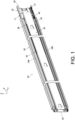
FIG. 1 is a diagram showing a slide rail kit according to a first embodiment of the present invention; -
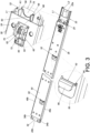
FIG. 2 is an exploded view of the slide rail kit comprising a first rail, a second rail and a third rail according to the first embodiment of the present invention; -
FIG. 3 is a diagram showing the first rail from a first viewing angle according to the first embodiment of the present invention; -
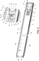
FIG. 4 is a diagram showing the first rail from a second viewing angle with a locking member being in a locking state according to the first embodiment of the present invention; -
FIG. 5 is a diagram showing the first rail from the second viewing angle with the locking member being in an unlocking state according to the first embodiment of the present invention; -
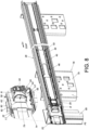
FIG. 6 is a diagram showing a process of mounting the slide rail kit to a rack according to the first embodiment of the present invention; -
FIG. 7 is a diagram showing the slide rail kit being mounted to the rack with the locking member being blocked by the rack according to the first embodiment of the present invention; -
FIG. 8 is a diagram showing the slide rail kit being on the rack with the locking member being no longer blocked by the rack according to the first embodiment of the present invention; -
FIG.9 is a diagram showing a slide rail kit according to a second embodiment of the present invention; -
FIG. 10 is an exploded view of the slide rail kit comprising a first rail, a second rail and a third rail according to the second embodiment of the present invention; -
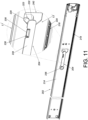
FIG. 11 is a diagram showing the first rail from a first viewing angle according to the second embodiment of the present invention; -
FIG. 12 is a diagram showing the first rail from a second viewing angle with a locking member being in a locking state according to the second embodiment of the present invention; -
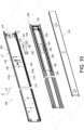
FIG. 13 is a diagram showing the slide rail kit being mounted to the rack with the locking member being blocked by the rack according to the second embodiment of the present invention; -
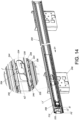
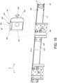
FIG. 14 is a diagram showing the slide rail kit being mounted on the rack from a first viewing angle with the locking member being no longer blocked by the rack according to the second embodiment of the present invention; and -
FIG. 15 is a diagram showing the slide rail kit being mounted on the rack from a second viewing angle with the locking member being no longer blocked by the rack according to the second embodiment of the present invention. - As shown in
FIG. 1 andFIG. 2 , aslide rail kit 20 comprises a first rail 22 (such as an outer rail) and alocking member 24 according to a first embodiment of the present invention. Preferably, theslide rail kit 20 further comprises abracket 26, a second rail 28 (such as a middle rail) and a third rail 30 (such as an inner rail) . Thefirst rail 22, thesecond rail 28 and thethird rail 30 are longitudinally movable relative to each other. In the present embodiment, the X-axis is a longitudinal direction (or a length direction of the slide rail), the Y-axis is a transverse direction (or a lateral direction of the slide rail), and the Z-axis is a vertical direction (or a height direction of the slide rail). - The
first rail 22 comprises aside wall 32. Preferably, thefirst rail 22 further comprises afirst wall 34a and asecond wall 34b. Theside wall 32 of thefirst rail 22 is connected between thefirst wall 34a and thesecond wall 34b of thefirst rail 22. Apassage 36 is defined by thefirst wall 34a, thesecond wall 34b and theside wall 32 of thefirst rail 22. Preferably, theside wall 32 of thefirst rail 22 has an outer side L1 and an inner side L2. Thesecond rail 28 is movably mounted in thepassage 36 of thefirst rail 22, and thesecond rail 28 is located at the inner side L2 of theside wall 32 of thefirst rail 22. In addition, thethird rail 30 is movably mounted in apassage 38 of thesecond rail 28. - The
bracket 26 is attached to thefirst rail 22. In the present embodiment, thebracket 26 is fixed to thefirst rail 22, such that thebracket 26 and thefirst rail 22 can be seen as one piece; or in an alternative embodiment, thebracket 26 can be integrated into thefirst rail 22. However, the present invention is not limited thereto. - The
locking member 24 is arranged on thefirst rail 22. Furthermore, thelocking member 24 is movably mounted to thebracket 26. - Preferably, the
slide rail kit 20 further comprises at least one firstslide assisting device 40 movably mounted between thefirst rail 22 and thesecond rail 28 and configured to assist relative movement between thefirst rail 22 and thesecond rail 28. Preferably, theslide rail kit 20 of the first embodiment comprises two firstslide assisting devices 40 located inside thepassage 36 of thefirst rail 22 and adjacent to thefirst wall 34a and thesecond wall 34b respectively, but the present invention is not limited thereto. Each of the firstslide assisting devices 40 comprises a plurality ofballs 41. Due to the viewing angle, only the firstslide assisting device 40 adjacent to thesecond wall 34b is shown inFIG. 1 andFIG. 2 . - Preferably, the
slide rail kit 20 further comprises a secondslide assisting device 42 movably mounted between thesecond rail 28 and thethird rail 30 and configured to assist relative movement between thesecond rail 28 and thethird rail 30. The secondslide assisting device 42 comprises aball retainer 44 and a plurality ofballs 46 mounted on theball retainer 44. - As shown in
FIG. 3 andFIG. 4 , thebracket 26 comprises afirst edge part 48a, asecond edge part 48b, and aside part 50 connected between thefirst edge part 48a and thesecond edge part 48b. Theside part 50 of thebracket 26 is fixed to the outer side L1 of theside wall 32 of the first rail 22 (as shown inFIG. 3 ), and thefirst edge part 48a and thesecond edge part 48b of thebracket 26 are configured to respectively hold thefirst wall 34a and thesecond wall 34b of thefirst rail 22, so as to improve structural strength or supporting strength of thefirst rail 22. - Furthermore, the
first rail 22 is arranged with at least one mountingfeature 52. In the present embodiment, the mountingfeature 52 is arranged on theside part 50 of thebracket 26 on the first rail 22 (as shown inFIG. 3 ). The mountingfeature 52 can be an insertion structure. Preferably, the mountingfeature 52 has a firstpredetermined section 54 and a secondpredetermined section 56. The firstpredetermined section 54 is transversely (laterally) extended from theside part 50 of thebracket 26. The secondpredetermined section 56 is bent relative to the firstpredetermined section 54. For example, the secondpredetermined section 56 is substantially perpendicularly connected to the firstpredetermined section 54, and the secondpredetermined section 56 is substantially parallel to a length direction of the first rail 22 (and the bracket 26) (as shown inFIG. 3 ), but the present invention is not limited thereto. - The locking
member 24 comprises at least one lockingpart 58 and an operatingpart 60. The lockingpart 58 is configured to be held at the outer side L1 of theside wall 32 of the first rail 22 (as shown inFIG. 3 ) in response to an elastic force F of anelastic structure 62. Furthermore, the lockingmember 24 is configured to be held in a locking state K1 in response to the elastic force F of theelastic structure 62, such that the lockingpart 58 of the lockingmember 24 is held at the outer side L1 of theside wall 32 of thefirst rail 22. - Preferably, the locking
member 24 is pivotally connected to thebracket 26 through ashaft member 64. In the present embodiment, the lockingmember 24 is pivotally connected to at least onelug 65 of thebracket 26 through theshaft member 64. - Preferably, the
elastic structure 62 comprises a firstelastic section 66, a secondelastic section 68 and amiddle part 70 connected between the firstelastic section 66 and the secondelastic section 68. Themiddle part 70 is mounted to theshaft member 64. The firstelastic section 66 contacts one of thebracket 26 and thefirst rail 22. In the present embodiment, the firstelastic section 66 is connected to apredetermined part 72 of thebracket 26. The secondelastic section 68 contacts the lockingmember 24. - Preferably, the
first rail 22 has afirst end part 22a and asecond end part 22b opposite to each other (such as a front end part and a rear end part) . The lockingmember 24 is located adjacent to thefirst end part 22a of thefirst rail 22. - Preferably, the
first rail 22 is formed with apredetermined hole 74 communicating the outer side L1 and the inner side L2 of theside wall 32. Thepredetermined hole 74 is arranged at a position at least corresponding to the operatingpart 60 of the lockingmember 24 so as to allow a user to easily operate the operatingpart 60 of the lockingmember 24 by a finger. - As shown in
FIG. 4 andFIG. 5 , if the user is going to operate the lockingmember 24 to move away from the locking state K1, the user can apply an operating force J to the lockingmember 24. For example, the finger of the user can pass through apredetermined space 75 of thepredetermined hole 74 from the inner side L2 of thefirst rail 22 to the outer side L1 of thefirst rail 22, and apply the operating force J to the operatingpart 60 of the lockingmember 24 in a direction opposite to the elastic force F to overcome the elastic force F, so as to move the lockingmember 24 to switch from the locking state K1 (as shown inFIG. 4 ) to an unlocking state K2 (as shown inFIG. 5 ), such that the lockingpart 58 of the lockingmember 24 is moved toward the inner side L2 of theside wall 32 of thefirst rail 22. - As shown in
FIG. 6 andFIG. 7 , theslide rail kit 20 can be mounted to arack 76. Therack 76 comprises at least one post, such as afirst post 78 and asecond post 80. However, the number of the posts is not limited. Thefirst post 78 of therack 76 comprises a plurality of mountingstructures 82 which are spaced apart from each other along a height direction of therack 76. In the present embodiment, the plurality of mountingstructures 82 are mounting holes, but the present invention is not limited thereto. Therack 76 further comprises a blockingwall 83. In the present embodiment, thesecond post 80 comprises the blockingwall 83, but the present invention is not limited thereto. In addition, the lockingpart 58 of the lockingmember 24 comprises a guidingsection 84, and the guidingsection 84 has an inclined surface or an arc surface. - Furthermore, the
slide rail kit 20 is configured to be mounted to the rack 76 (as shown inFIG. 7 ) . During such mounting process, the mountingfeature 52 on thebracket 26 of thefirst rail 22 can be transversely (laterally) inserted into the mounting structure 82 (the mounting hole) . In the meantime, thefirst rail 22 is located at a predetermined position P1 relative to the rack 76 (as shown inFIG. 6 ), and the guidingsection 84 of the lockingpart 58 corresponds to or contacts a lateral side of the blockingwall 83 of therack 76, such that theelastic structure 62 is in a state of accumulating the elastic force F (as shown inFIG. 6 ) . - When the
first rail 22 is moved relative to therack 76 from the predetermined position P1 along a first predetermined direction D1 (as shown inFIG. 6 ) to a mounting position P2 (as shown inFIG. 7 ), the mountingfeature 52 of thefirst rail 22 is configured to mount thefirst rail 22 to the mountingstructure 82 of therack 76. Specifically, the mountingfeature 52 of thefirst rail 22 is configured to be mounted to the mountingstructure 82 and blocked by a hole wall W of the mountingstructure 82 in order to prevent thefirst rail 22 from being moved relative to therack 76 along the first predetermined direction D1. In addition, when thefirst rail 22 is located at the mounting position P2 relative to the rack 76 (as shown inFIG. 7 ), the guidingsection 84 of the lockingpart 58 no longer corresponds to (or no longer contacts) the lateral side of the blockingwall 83 of therack 76, such that the lockingmember 24 is in the locking state K1 (as shown inFIG. 7 ) in response to the elastic force F released by theelastic structure 62. Furthermore, the lockingpart 58 is configured to be held at the outer side L1 of theside wall 32 of thefirst rail 22 in response to the elastic force F of theelastic structure 62 to be in a state being blocked by therack 76, such that the lockingpart 58 of the lockingmember 24 is configured to be blocked by the blockingwall 83 of thesecond post 80 of therack 76. In other words, the lockingpart 58 of the lockingmember 24 is blocked by the blockingwall 83 of therack 76, in order to prevent thefirst rail 22 from being moved along a second predetermined direction D2 relative to therack 76, such that the mountingfeature 52 of thefirst rail 22 cannot be detached from the mounting structure 82 (as shown inFIG. 7 ) . In addition, the second predetermined direction D2 is opposite to the first predetermined direction D1. - Preferably, when the
first rail 22 is located at the mounting position P2 relative to the rack 76 (as shown inFIG. 7 ), the firstpredetermined section 54 of the mountingfeature 52 is blocked by the hole wall W of the mountingstructure 82 in the first predetermined direction D1, and the firstpredetermined section 54 of the mountingfeature 52 is blocked by anupper hole wall 77 and alower hole wall 79 of the mountingstructure 82 in the height direction to prevent thefirst rail 22 from being moved relative to therack 76 along the height direction. In addition, the secondpredetermined section 56 of the mountingfeature 52 is configured to hold a predetermined lateral surface 86 (please refer toFIG. 6 ) adjacent to the hole wall W. - As shown in
FIG. 7 andFIG. 8 , when the user is going to detach thefirst rail 22 from therack 76, the user can apply the operating force J to the operatingpart 60 of the lockingmember 24, so as to move the lockingmember 24 to switch from the locking state K1 (as shown inFIG. 7 ) to the unlocking state K2 (as shown inFIG. 8 ). In other words, the operatingpart 60 can be operated to move the lockingpart 58 toward the inner side L2 of theside wall 32, so as to prevent the lockingpart 58 of the lockingmember 24 from being blocked by the blockingwall 83 of the rack 76 (as shown inFIG. 8 ), such that the lockingpart 58 of the lockingmember 24 is no longer in the state being blocked by the blockingwall 83 of therack 76. Therefore, thefirst rail 22 is movable relative to therack 76 from the mounting position P2 along the second predetermined direction D2, and the mountingfeature 52 can be detached and separated from the mountingstructure 82 of therack 76, so as to detach thefirst rail 22 from therack 76. - Preferably, when the user is going to detach the
first rail 22 from therack 76, the user can first detach thethird rail 30 from thepassage 38 of the second rail 28 (thethird rail 30 is not shown inFIG. 8 ) . When thethird rail 30 is detached from thepassage 38 of thesecond rail 28 and when thesecond rail 28 is located at a retracted position R relative to the first rail 22 (as shown inFIG. 8 ), thesecond rail 28 does not cover the operatingpart 60 of the lockingmember 24, such that the user can easily operate the lockingmember 24 from the inner side L2 of theside wall 32 of thefirst rail 22. For example, the finger of the user can pass through thepredetermined space 75 of thepredetermined hole 74 from the inner side L2 of thefirst rail 22 to the outer side L1 of thefirst rail 22, and apply the operating force J to the operatingpart 60 of the lockingmember 24, in order to move the lockingmember 24 to switch from the locking state K1 (as shown inFIG. 7 ) to the unlocking state K2 (as shown inFIG. 8 ), such that the lockingpart 58 of the lockingmember 24 is moved away from the state being blocked by the blockingwall 83 of therack 76. -
FIG. 9 andFIG. 10 show aslide rail kit 200 according to a second embodiment of the present invention. In contrast to theslide rail kit 20 of the first embodiment, a lockingmember 204 of theslide rail kit 200 of the second embodiment has different configuration. - Furthermore, a
first rail 202 comprises afirst wall 212a, asecond wall 212b and aside wall 214 connected between thefirst wall 212a and thesecond wall 212b. Apassage 216 is defined by thefirst wall 212a, thesecond wall 212b and theside wall 214 of thefirst rail 202. Asecond rail 208 is movably mounted in thepassage 216 of thefirst rail 202, and thesecond rail 208 is located at an inner side L2' of aside wall 214 of thefirst rail 202. - Preferably, the
slide rail kit 200 further comprises at least one firstslide assisting device 218 movably mounted between thefirst rail 202 and thesecond rail 208, and configured to assist relative movement between thefirst rail 202 and thesecond rail 208. Preferably, theslide rail kit 200 of the second embodiment comprises two firstslide assisting devices 218 respectively located inside thepassage 216 of thefirst rail 202 and adjacent to thefirst wall 212a and thesecond wall 212b respectively, but the present invention is not limited thereto. Each of the firstslide assisting devices 218 comprises a plurality ofballs 220. Due to the viewing angle, only the firstslide assisting device 218 adjacent to thesecond wall 212b is shown inFIG. 10 . - A
third rail 210 is movably mounted in apassage 222 of thesecond rail 208, and a secondslide assisting device 224 is movably mounted between thesecond rail 208 and thethird rail 210 and configured to assist relative movement between thesecond rail 208 and thethird rail 210. The secondslide assisting device 224 comprises aball retainer 226 and a plurality ofballs 228 mounted on theball retainer 226. - As shown in
FIG. 10 ,FIG. 11 andFIG. 12 , thefirst rail 202 is arranged with at least one mounting feature 223 (as shown inFIG. 11 andFIG. 12 ). In the present embodiment, the mountingfeature 223 is arranged on an outer side L1' of theside wall 214 of thefirst rail 202, and the mountingfeature 223 is an insertion structure, but the present is not limited thereto. Preferably, thefirst rail 202 is arranged with anauxiliary member 225 attached (such as fixed) to the outer side L1' of theside wall 214 of thefirst rail 202, such that theauxiliary member 225 and thefirst rail 202 can be seen as one piece (as shown inFIG. 12 ) ; or in an alternative embodiment, theauxiliary member 225 can be integrated into thefirst rail 202. However, the present invention is not limited thereto. The mountingfeature 223 is arranged on theauxiliary member 225. - Preferably, the mounting
feature 223 has a firstpredetermined section 227 and a secondpredetermined section 229. The firstpredetermined section 227 is transversely (laterally) extended from a side part of theauxiliary member 225. The secondpredetermined section 229 is bent relative to the firstpredetermined section 227. For example, the secondpredetermined section 229 is substantially perpendicularly connected to the firstpredetermined section 227, and the secondpredetermined section 229 is substantially parallel to a length direction of the first rail 202 (and the auxiliary member 225) (as shown inFIG. 12 ), but the present invention is not limited thereto. - The locking
member 204 comprises a lockingpart 230, an operatingpart 232 and anelastic structure 234. Theelastic structure 234 is connected (such as fixed) to the inner side L2' of theside wall 214 of thefirst rail 202 through a connecting member 236 (as shown inFIG. 10 andFIG. 11 ) . Theelastic structure 234 has a predetermined longitudinal length. Preferably, the lockingpart 230 is arranged on theelastic structure 234, and theoperating part 232 is operably connected to the lockingpart 230. In the present embodiment, the lockingpart 230, theelastic structure 234 and theoperating part 232 are integrated into the lockingmember 204 as a single component. The lockingpart 230 is configured to be held at the outer side L1' of theside wall 214 of the first rail 202 (as shown inFIG. 12 ) in response to an elastic force of theelastic structure 234. Furthermore, the lockingmember 204 is configured to be held in a locking state K1' in response to the elastic force of theelastic structure 234, such that the lockingpart 230 of the lockingmember 204 is held at the outer side L1' of theside wall 214 of thefirst rail 202. - Preferably, the
first rail 202 is formed with anauxiliary hole 238 communicating the outer side L1' and the inner side L2' of theside wall 214 of thefirst rail 202, and the lockingpart 230 of the lockingmember 204 is partially extended from the inner side L2' of theside wall 214 of thefirst rail 202 to the outer side L1' of theside wall 214 of thefirst rail 202 through theauxiliary hole 238. Theauxiliary member 225 has acorresponding hole 240 corresponding to theauxiliary hole 238. Thecorresponding hole 240 is configured to allow thelocking part 230 of the lockingmember 204 to pass through to be located at the outer side L1' of theside wall 214 of the first rail 202 (as shown inFIG. 12 ). - Preferably, the
first rail 202 is formed with apredetermined hole 242 communicating the outer side L1' and the inner side L2' of theside wall 214 of thefirst rail 202. Thepredetermined hole 242 is arranged at a position at least corresponding to theoperating part 232 of the lockingmember 204 so as to allow the user to easily operate theoperating part 232 of the lockingmember 204 by the finger. - Preferably, the locking
part 230 of the lockingmember 204 comprises aguiding section 243. For example, the guidingsection 243 has an inclined surface or an arc surface (as shown inFIG. 12 ) . - Preferably, the
second rail 208 has anopening 244, and theball retainer 226 has a throughhole 246 corresponding to theopening 244 of the second rail 208 (as shown inFIG. 10 ). - As shown in
FIG. 13 , theslide rail kit 200 is applicable to arack 248. Therack 248 comprises a plurality of mountingstructures 250. In the present embodiment, the plurality of mountingstructures 250 are mounting holes, but the present invention is not limited thereto. Each of the mountingstructures 250 is defined by a plurality of hole walls, such as a first hole wall W1 and a second hole wall W2. The first hole wall W1 and the second hole wall W2 are a front hole wall and a rear hole wall respectively. - Furthermore, the
slide rail kit 200 is configured to be mounted to therack 248. During such mounting process, the mountingfeature 223 thefirst rail 202 can be transversely (laterally) inserted into the mounting structure 250 (the mounting hole) . When thefirst rail 202 is moved relative to therack 248 from a predetermined position along a second predetermined direction D2 to a mounting position P2', the mountingfeature 223 of thefirst rail 202 is configured to mount thefirst rail 202 to the mountingstructure 250 of therack 248. Specifically, the mountingfeature 223 of thefirst rail 202 is configured to be mounted to the mountingstructure 250 and blocked by the first hole wall W1 of the mountingstructure 250 in order to prevent thefirst rail 202 from being moved relative to therack 248 along the second predetermined direction D2. In addition, when thefirst rail 202 is located at the mounting position P2' relative to therack 248, the guidingsection 243 of the lockingpart 230 has crossed a lateral surface adjacent to the second hole wall W2 of therack 248, such that the lockingmember 204 is in the locking state K1' in response to an elastic force F' released by theelastic structure 234. Furthermore, the lockingpart 230 is configured to be held at the outer side L1' of theside wall 214 of thefirst rail 202 in response to the elastic force F' of theelastic structure 234 to be in a state being blocked by therack 248, such that the lockingpart 230 of the lockingmember 204 is configured to be blocked by the second hole wall W2 of the mountingstructure 250 of therack 248. In other words, the lockingpart 230 of the lockingmember 204 is blocked by the second hole wall W2 of therack 248, in order to prevent thefirst rail 202 from being moved along a first predetermined direction D1 relative to therack 248, such that the mountingfeature 223 of thefirst rail 202 cannot be detached from the mountingstructure 250. In addition, the first predetermined direction D1 is opposite to the second predetermined direction D2. - Preferably, when the
first rail 202 is located at the mounting position P2' relative to therack 248, the firstpredetermined section 227 of the mountingfeature 223 is blocked by the first hole wall W1 of the mountingstructure 250 in the second predetermined direction D2, and the firstpredetermined section 227 of the mountingfeature 223 is blocked by anupper hole wall 252 and alower hole wall 254 of the mountingstructure 250 in the height direction to prevent thefirst rail 202 from being moved relative to therack 248 along the height direction. In addition, the secondpredetermined section 229 of the mountingfeature 223 is configured to hold a predeterminedlateral surface 256 adjacent to the first hole wall W1. - As shown in
FIG. 14 andFIG. 15 , when the user is going to detach thefirst rail 202 from therack 248, the user can apply an operating force J' to theoperating part 232 of the locking member 204 (as shown inFIG. 14 ), so as to move the lockingmember 204 to switch from the locking state K1' to an unlocking state K2'. In other words, the operatingpart 232 can be operated to move the lockingpart 230 toward the inner side L2' of theside wall 214, so as to prevent thelocking part 230 of the lockingmember 204 from being blocked by the second hole wall W2 of the rack 248 (as shown inFIG. 15 ), such that the lockingpart 230 of the lockingmember 204 is no longer in the state being blocked by the second hole wall W2 of therack 248. Therefore, thefirst rail 202 is movable relative to therack 248 from the mounting position P2' along the first predetermined direction D1, and the mountingfeature 223 can be detached and separated from the mountingstructure 250 of therack 248, so as to detach thefirst rail 202 from therack 248. - Preferably, when the user is going to detach the
first rail 202 from therack 248, the user can first detach thethird rail 210 from thepassage 222 of the second rail 208 (thethird rail 210 is not shown inFIG. 14 ) . When thethird rail 210 is detached from thepassage 222 of thesecond rail 208 and when thesecond rail 208 is located at a retracted position R' relative to the first rail 202 (as shown inFIG. 14 ), theopening 244 of thesecond rail 208 corresponds to theoperating part 232 of the lockingmember 204. In other words, thesecond rail 208 does not cover theoperating part 232 of the lockingmember 204, such that the user can easily operate the lockingmember 204 from the inner side L2' of theside wall 214 of the first rail 202 (as shown inFIG. 14 ). Preferably, the throughhole 246 of theball retainer 226 of the secondslide assisting device 224 corresponds to theopening 244 of thesecond rail 208. Accordingly, the operatingpart 232 of the lockingmember 204 can be exposed to allow the user to easily operate the lockingmember 204 from the inner side L2' of theside wall 214 of the first rail 202 (as shown inFIG. 14 ). For example, the user can easily apply the operating force J' by the finger to theoperating part 232 of the lockingmember 204 through thepredetermined hole 242 from the inner side L2' of thefirst rail 202, so as to move the lockingmember 204 to switch from the locking state K1' to the unlocking state K2' (as shown inFIG. 14 andFIG. 15 ), such that the lockingpart 230 of the lockingmember 204 is moved away from the state being blocked by the second hole wall W2 of the rack 248 (as shown inFIG. 15 ) . As such, thefirst rail 202 is movable relative to therack 248 from the mounting position P2' along the first predetermined direction D1, and the mountingfeature 223 can be detached and separated from the mountingstructure 250 of therack 248, so as to detach thefirst rail 202 from therack 248. - Therefore, the slide rail kit (20, 200) according to the embodiment of the present invention has the following technical features:
- 1. The slide rail kit (20, 200) can be rapidly mounted to the rack (76, 248) or detached from the rack (76, 248) by the user without a tool.
- 2. In the first embodiment, the locking
member 24 is movable relative to the first rail 22 (or the bracket 26). For example, the lockingmember 24 is pivotally connected to thebracket 26 on thefirst rail 22. When thefirst rail 22 is mounted to the mountingstructure 82 of therack 76 through the mountingfeature 52 on the first rail 22 (or the bracket 26), the lockingpart 58 of the lockingmember 24 is configured to be held at the outer side L1 of theside wall 32 of thefirst rail 22 in response to the elastic force F of theelastic structure 62 to be in the state being blocked by therack 76, such that the mountingfeature 52 of thefirst rail 22 cannot be detached from the mountingstructure 82 of therack 76 . - 3. In the first embodiment, when the
second rail 28 is located at the retracted position R relative to thefirst rail 22, thesecond rail 28 does not cover the operatingpart 60 of the lockingmember 24, such that the user can easily operate the lockingmember 24 from the inner side L2 of theside wall 32 of thefirst rail 22. For example, the user can apply the operating force J to the operatingpart 60 of the lockingmember 24, to move the lockingmember 24 to switch from the locking state K1 to the unlocking state K2. Therefore, the lockingmember 24 is no longer in the state being blocked by therack 76, such that the mountingfeature 52 of thefirst rail 22 can be detached from the mountingstructure 82 of therack 76. According to such arrangement, the slide rail kit can meet different market requirements. - 4. In the second embodiment, the locking
part 230, theelastic structure 234 and theoperating part 232 are integrated into the lockingmember 204 as a single component. The lockingmember 204 is connected (such as fixed) to thefirst rail 202 through theelastic structure 234. The mountingfeature 223 on thefirst rail 202 is configured to be mounted to the mountingstructure 250 of therack 248, and the lockingpart 230 of the locking member is configured to be held at the outer side L1' of theside wall 214 of thefirst rail 202 in response to the elastic force F' of theelastic structure 234 to be in the state being blocked by therack 248, such that the mountingfeature 223 of thefirst rail 202 cannot be detached from the mountingstructure 250 of therack 248. - 5. In the second embodiment, when the
second rail 208 is located at the retracted position R' relative to thefirst rail 202, theopening 244 of thesecond rail 208 corresponds to theoperating part 232 of the lockingmember 204. In other words, thesecond rail 208 does not cover theoperating part 232 of the lockingmember 204, such that the user can easily operate the lockingmember 204 from the inner side L2' of theside wall 214 of thefirst rail 202 to move the lockingmember 204 to switch from the locking state K1' to the unlocking state K2', such that the mountingfeature 223 of thefirst rail 202 can be detached from the mountingstructure 250 of therack 248. According to such arrangement, the slide rail kit can meet different market requirements
Claims (15)
- A slide rail kit (20, 200) applicable to a rack (76, 248), the slide rail kit (20, 200) comprising:a first rail (22, 202) comprising a side wall (32, 214), wherein the first rail (22, 202) has a mounting feature (52, 223), and the side wall (32, 214) has an inner side and an outer side facing toward the rack (76, 248); andcharacterized by:a locking member (24, 204) arranged on the first rail (22, 202) and comprising a locking part (58, 230) and an operating part (60, 232);wherein the mounting feature (52, 223) is configured to mount the first rail (22, 202) to a mounting structure (82, 250) of the rack (76, 248);wherein the locking part (58, 230) is configured to be held at the outer side of the side wall (32, 214) of the first rail (22, 202) to be blocked by the rack (76, 248) in response to an elastic force of an elastic structure (62, 234);wherein the operating part (60, 232) is configured to be operated to move the locking part (58, 230) toward the inner side of the side wall (32, 214) of the first rail (22, 202), such that the locking part (58, 230) is no longer blocked by the rack (76, 248).
- The slide rail kit of claim 1, characterized in that the mounting structure (82, 250) of the rack (76, 248) is a mounting hole, and the mounting feature (52, 223) of the first rail (22, 202) is configured to be mounted to the mounting hole and blocked by a hole wall of the mounting hole to prevent the first rail (22, 202) from being moved relative to the rack (76, 248) along a first predetermined direction; wherein when the locking part (58, 230) is blocked by the rack (76, 248), the locking part (58, 230) is configured to prevent the first rail (22, 202) from being moved relative to the rack (76, 248) along a second predetermined direction different from the first predetermined direction.
- The slide rail kit of claim 1 or 2, further characterized by a bracket (26) attached to the first rail (22), wherein the mounting feature (52) is arranged on the bracket (26) on the first rail (22), and the locking member (24) is movably mounted to the bracket (26) on the first rail (22).
- The slide rail kit of claim 3, characterized in that the locking member (24) is pivotally connected to the bracket (26) on the first rail (22) through a shaft member (64).
- The slide rail kit of claim 4, characterized in that the elastic structure (62) comprises a first elastic section (66) and a second elastic section (68), the first elastic section (66) is configured to contact one of the bracket (26) and the first rail (22), and the second elastic section (68) is configured to contact the locking member (24).
- The slide rail kit of claim 1, characterized in that the first rail (22) has a first end part and a second end part opposite to each other, and the locking member (24) is located adjacent to the first end part of the first rail (22).
- The slide rail kit of any of claims 1-6, characterized in that the first rail (22, 202) is formed with a predetermined hole (74, 242) communicating the outer side and the inner side of the side wall (32, 214), and the predetermined hole (74, 242) at least corresponds to the operating part (60, 232) of the locking member (204) .
- The slide rail kit of claim 7, characterized in that the first rail (22, 202) further comprises a first wall and a second wall, the side wall (32, 214) is connected between the first wall and the second wall, and a passage (36, 216) is defined by the first wall, the second wall and the side wall (32, 214); wherein the slide rail kit (20, 200) further comprises a second rail (28, 208) movably mounted in the passage (36, 216) of the first rail (22, 202), and the second rail (28, 208) is located at the inner side of the side wall (32, 214) of the first rail (22, 202); wherein when the second rail (28, 208) is located at a retracted position relative to the first rail (22, 202), the second rail (28, 208) does not cover the operating part (60, 232).
- The slide rail kit of claim 8, further characterized by at least one first slide assisting device (40, 218) mounted between the first rail (22, 202) and the second rail (28, 208) and configured to assist relative movement between the first rail (22, 202) and the second rail (28, 208).
- The slide rail kit of claim 9, further characterized by a third rail (30, 210) movably mounted to the second rail (28, 208), and a second slide assisting device (42, 224) mounted between the second rail (28, 208) and the third rail (30, 210) and configured to assist relative movement between the second rail (28, 208) and the third rail (30, 210).
- The slide rail kit of claim 1, characterized in that the first rail (202) further comprises a first wall and a second wall, the side wall (214) is connected between the first wall and the second wall, and a passage (216) is defined by the first wall, the second wall and the side wall; wherein the slide rail kit (200) further comprises a second rail (208) movably mounted in the passage (216) of the first rail (202), and the second rail (208) is located at an inner side of the side wall (214) of the first rail (202); wherein the locking part (230), the elastic structure (234) and the operating part (232) are integrated into the locking member (204), and the locking member (204) is connected to the first rail (202) through the elastic structure (234).
- The slide rail kit of claim 11, characterized in that the locking part (230) of the locking member (204) partially extends from the inner side of the side wall (214) of the first rail (202) to the outer side of the side wall (214) of the first rail (202) .
- The slide rail kit of claim 11, characterized in that the first rail (202) is formed with a predetermined hole (242) communicating the outer side and the inner side of the side wall (214), and the predetermined hole (242) at least corresponds to the operating part (232) of the locking member (204) ; the second rail (208) has an opening (244); when the second rail (208) is located at a retracted position relative to the first rail (202), the opening (244) of the second rail (208) corresponds to the operating part (232) of the locking member (204).
- The slide rail kit of claim 13, further characterized by at least one first slide assisting device (218) mounted between the first rail (202) and the second rail (208) and configured to assist relative movement between the first rail (202) and the second rail (208) ; wherein the slide rail kit (200) further comprises a third rail (210) movably mounted to the second rail (208), and a second slide assisting device (224) mounted between the second rail (208) and the third rail (210) and configured to assist relative movement between the second rail (208) and the third rail (210) .
- The slide rail kit of claim 14, characterized in that the second slide assisting device (224) comprises a ball retainer (226) and a plurality of balls (228) mounted on the ball retainer (226), and the ball retainer (226) is formed with a through hole (246) corresponding to the opening (244) of the second rail (208).
Applications Claiming Priority (1)
| Application Number | Priority Date | Filing Date | Title |
|---|---|---|---|
| TW112140960A TWI847899B (en) | 2023-10-24 | 2023-10-24 | Slide rail kit |
Publications (1)
| Publication Number | Publication Date |
|---|---|
| EP4546960A1 true EP4546960A1 (en) | 2025-04-30 |
Family
ID=90789349
Family Applications (1)
| Application Number | Title | Priority Date | Filing Date |
|---|---|---|---|
| EP24170755.3A Pending EP4546960A1 (en) | 2023-10-24 | 2024-04-17 | Slide rail kit |
Country Status (4)
| Country | Link |
|---|---|
| US (1) | US20250129637A1 (en) |
| EP (1) | EP4546960A1 (en) |
| JP (1) | JP7782790B2 (en) |
| TW (1) | TWI847899B (en) |
Citations (4)
| Publication number | Priority date | Publication date | Assignee | Title |
|---|---|---|---|---|
| JP2018061827A (en) * | 2016-10-12 | 2018-04-19 | 川湖科技股▲分▼有限公司 | Bracket device |
| US20200107636A1 (en) * | 2018-10-04 | 2020-04-09 | King Slide Works Co., Ltd. | Slide Rail Assembly |
| EP3886546A1 (en) * | 2020-03-25 | 2021-09-29 | King Slide Works Co., Ltd. | Slide rail assembly |
| US11647836B2 (en) | 2020-09-24 | 2023-05-16 | King Slide Works Co., Ltd. | Slide rail kit |
Family Cites Families (11)
| Publication number | Priority date | Publication date | Assignee | Title |
|---|---|---|---|---|
| US9681573B2 (en) * | 2014-10-07 | 2017-06-13 | King Slide Works Co., Ltd. | Slide rail assembly |
| EP3005901B1 (en) * | 2014-10-08 | 2019-05-22 | King Slide Works Co., Ltd. | Slide rail assembly |
| TWI607722B (en) * | 2015-05-15 | 2017-12-11 | 川湖科技股份有限公司 | Slide rail assembly |
| TWI598026B (en) * | 2015-09-18 | 2017-09-01 | King Slide Works Co Ltd | Slide rail assembly with interlock device |
| US9743767B1 (en) * | 2016-04-14 | 2017-08-29 | Seagate Technology Llc | Tool-free quick install rail-kit for rack systems |
| US10485132B2 (en) * | 2016-05-27 | 2019-11-19 | Hewlett Packard Enterprise Development Lp | Rail kits |
| TWI619423B (en) * | 2016-09-13 | 2018-03-21 | 川湖科技股份有限公司 | Bracket device |
| TWI649046B (en) * | 2018-03-08 | 2019-02-01 | 川湖科技股份有限公司 | Slide rail assembly and bracket device thereof |
| TWI664892B (en) * | 2018-05-30 | 2019-07-01 | 川湖科技股份有限公司 | Bracket device for rack system and slide rail assembly |
| TWI674859B (en) * | 2018-11-12 | 2019-10-21 | 川湖科技股份有限公司 | Bracket device |
| TWI702020B (en) * | 2019-06-12 | 2020-08-21 | 川湖科技股份有限公司 | Slide rail assembly |
-
2023
- 2023-10-24 TW TW112140960A patent/TWI847899B/en active
-
2024
- 2024-03-13 US US18/603,939 patent/US20250129637A1/en active Pending
- 2024-04-17 EP EP24170755.3A patent/EP4546960A1/en active Pending
- 2024-05-29 JP JP2024086765A patent/JP7782790B2/en active Active
Patent Citations (4)
| Publication number | Priority date | Publication date | Assignee | Title |
|---|---|---|---|---|
| JP2018061827A (en) * | 2016-10-12 | 2018-04-19 | 川湖科技股▲分▼有限公司 | Bracket device |
| US20200107636A1 (en) * | 2018-10-04 | 2020-04-09 | King Slide Works Co., Ltd. | Slide Rail Assembly |
| EP3886546A1 (en) * | 2020-03-25 | 2021-09-29 | King Slide Works Co., Ltd. | Slide rail assembly |
| US11647836B2 (en) | 2020-09-24 | 2023-05-16 | King Slide Works Co., Ltd. | Slide rail kit |
Also Published As
| Publication number | Publication date |
|---|---|
| JP7782790B2 (en) | 2025-12-09 |
| TWI847899B (en) | 2024-07-01 |
| JP2025072277A (en) | 2025-05-09 |
| US20250129637A1 (en) | 2025-04-24 |
| TW202517183A (en) | 2025-05-01 |
Similar Documents
| Publication | Publication Date | Title |
|---|---|---|
| EP3975674B1 (en) | Slide rail kit | |
| EP3505007B1 (en) | Slide rail assembly | |
| US10806256B1 (en) | Slide rail assembly | |
| EP3322269A1 (en) | Bracket device and slide rail assembly comprising the same | |
| US6413122B2 (en) | Wrong insertion preventing mechanism | |
| EP3567994B1 (en) | Slide rail assembly and slide rail kit thereof | |
| EP3505008B1 (en) | Slide rail assembly | |
| EP3352546A1 (en) | Slide rail assembly | |
| EP3352547A1 (en) | Slide rail assembly | |
| EP3253189A1 (en) | Slide rail device | |
| EP3300348A1 (en) | Rail mounting adapter assembly for rack | |
| EP3292789A1 (en) | Slide rail assembly and rail kit thereof | |
| EP3576507B1 (en) | Bracket device for rack system and slide rail assembly | |
| EP3505009B1 (en) | Slide rail assembly | |
| EP3656251A1 (en) | Slide rail assembly | |
| US10736230B2 (en) | Cable management assembly | |
| US20120075815A1 (en) | Electronic apparatus | |
| EP3886546A1 (en) | Slide rail assembly | |
| EP3193569A1 (en) | Bracket device | |
| EP4537705B1 (en) | Slide rail assembly | |
| EP4548808B1 (en) | Slide rail assembly | |
| US20250129637A1 (en) | Slide rail kit | |
| US10076051B2 (en) | Structure for fixing printed board in electronic device unit | |
| EP3914057B1 (en) | Slide rail assembly | |
| EP4666911A1 (en) | Slide rail assembly |
Legal Events
| Date | Code | Title | Description |
|---|---|---|---|
| PUAI | Public reference made under article 153(3) epc to a published international application that has entered the european phase |
Free format text: ORIGINAL CODE: 0009012 |
|
| STAA | Information on the status of an ep patent application or granted ep patent |
Free format text: STATUS: REQUEST FOR EXAMINATION WAS MADE |
|
| 17P | Request for examination filed |
Effective date: 20241223 |
|
| AK | Designated contracting states |
Kind code of ref document: A1 Designated state(s): AL AT BE BG CH CY CZ DE DK EE ES FI FR GB GR HR HU IE IS IT LI LT LU LV MC ME MK MT NL NO PL PT RO RS SE SI SK SM TR |