EP4546955A1 - Motherboard assembly, motherboard module and assembling method thereof - Google Patents
Motherboard assembly, motherboard module and assembling method thereof Download PDFInfo
- Publication number
- EP4546955A1 EP4546955A1 EP24188653.0A EP24188653A EP4546955A1 EP 4546955 A1 EP4546955 A1 EP 4546955A1 EP 24188653 A EP24188653 A EP 24188653A EP 4546955 A1 EP4546955 A1 EP 4546955A1
- Authority
- EP
- European Patent Office
- Prior art keywords
- motherboard
- sealing component
- electrical connector
- extension part
- disposed
- Prior art date
- Legal status (The legal status is an assumption and is not a legal conclusion. Google has not performed a legal analysis and makes no representation as to the accuracy of the status listed.)
- Pending
Links
Images




Classifications
-
- H—ELECTRICITY
- H01—ELECTRIC ELEMENTS
- H01R—ELECTRICALLY-CONDUCTIVE CONNECTIONS; STRUCTURAL ASSOCIATIONS OF A PLURALITY OF MUTUALLY-INSULATED ELECTRICAL CONNECTING ELEMENTS; COUPLING DEVICES; CURRENT COLLECTORS
- H01R13/00—Details of coupling devices of the kinds covered by groups H01R12/70 or H01R24/00 - H01R33/00
- H01R13/46—Bases; Cases
- H01R13/52—Dustproof, splashproof, drip-proof, waterproof, or flameproof cases
- H01R13/5219—Sealing means between coupling parts, e.g. interfacial seal
-
- H—ELECTRICITY
- H01—ELECTRIC ELEMENTS
- H01R—ELECTRICALLY-CONDUCTIVE CONNECTIONS; STRUCTURAL ASSOCIATIONS OF A PLURALITY OF MUTUALLY-INSULATED ELECTRICAL CONNECTING ELEMENTS; COUPLING DEVICES; CURRENT COLLECTORS
- H01R12/00—Structural associations of a plurality of mutually-insulated electrical connecting elements, specially adapted for printed circuits, e.g. printed circuit boards [PCB], flat or ribbon cables, or like generally planar structures, e.g. terminal strips, terminal blocks; Coupling devices specially adapted for printed circuits, flat or ribbon cables, or like generally planar structures; Terminals specially adapted for contact with, or insertion into, printed circuits, flat or ribbon cables, or like generally planar structures
- H01R12/50—Fixed connections
- H01R12/59—Fixed connections for flexible printed circuits, flat or ribbon cables or like structures
- H01R12/592—Fixed connections for flexible printed circuits, flat or ribbon cables or like structures connections to contact elements
-
- H—ELECTRICITY
- H05—ELECTRIC TECHNIQUES NOT OTHERWISE PROVIDED FOR
- H05K—PRINTED CIRCUITS; CASINGS OR CONSTRUCTIONAL DETAILS OF ELECTRIC APPARATUS; MANUFACTURE OF ASSEMBLAGES OF ELECTRICAL COMPONENTS
- H05K3/00—Apparatus or processes for manufacturing printed circuits
- H05K3/22—Secondary treatment of printed circuits
- H05K3/28—Applying non-metallic protective coatings
- H05K3/284—Applying non-metallic protective coatings for encapsulating mounted components
-
- G—PHYSICS
- G06—COMPUTING OR CALCULATING; COUNTING
- G06F—ELECTRIC DIGITAL DATA PROCESSING
- G06F1/00—Details not covered by groups G06F3/00 - G06F13/00 and G06F21/00
- G06F1/16—Constructional details or arrangements
- G06F1/18—Packaging or power distribution
- G06F1/183—Internal mounting support structures, e.g. for supporting printed circuit boards
- G06F1/184—Mounting of motherboards
-
- G—PHYSICS
- G06—COMPUTING OR CALCULATING; COUNTING
- G06F—ELECTRIC DIGITAL DATA PROCESSING
- G06F1/00—Details not covered by groups G06F3/00 - G06F13/00 and G06F21/00
- G06F1/16—Constructional details or arrangements
- G06F1/18—Packaging or power distribution
- G06F1/183—Internal mounting support structures, e.g. for supporting printed circuit boards
- G06F1/185—Mounting of expansion boards
-
- H—ELECTRICITY
- H01—ELECTRIC ELEMENTS
- H01R—ELECTRICALLY-CONDUCTIVE CONNECTIONS; STRUCTURAL ASSOCIATIONS OF A PLURALITY OF MUTUALLY-INSULATED ELECTRICAL CONNECTING ELEMENTS; COUPLING DEVICES; CURRENT COLLECTORS
- H01R12/00—Structural associations of a plurality of mutually-insulated electrical connecting elements, specially adapted for printed circuits, e.g. printed circuit boards [PCB], flat or ribbon cables, or like generally planar structures, e.g. terminal strips, terminal blocks; Coupling devices specially adapted for printed circuits, flat or ribbon cables, or like generally planar structures; Terminals specially adapted for contact with, or insertion into, printed circuits, flat or ribbon cables, or like generally planar structures
- H01R12/70—Coupling devices
- H01R12/71—Coupling devices for rigid printing circuits or like structures
-
- H—ELECTRICITY
- H01—ELECTRIC ELEMENTS
- H01R—ELECTRICALLY-CONDUCTIVE CONNECTIONS; STRUCTURAL ASSOCIATIONS OF A PLURALITY OF MUTUALLY-INSULATED ELECTRICAL CONNECTING ELEMENTS; COUPLING DEVICES; CURRENT COLLECTORS
- H01R43/00—Apparatus or processes specially adapted for manufacturing, assembling, maintaining, or repairing of line connectors or current collectors or for joining electric conductors
- H01R43/002—Maintenance of line connectors, e.g. cleaning
-
- H—ELECTRICITY
- H01—ELECTRIC ELEMENTS
- H01R—ELECTRICALLY-CONDUCTIVE CONNECTIONS; STRUCTURAL ASSOCIATIONS OF A PLURALITY OF MUTUALLY-INSULATED ELECTRICAL CONNECTING ELEMENTS; COUPLING DEVICES; CURRENT COLLECTORS
- H01R43/00—Apparatus or processes specially adapted for manufacturing, assembling, maintaining, or repairing of line connectors or current collectors or for joining electric conductors
- H01R43/005—Apparatus or processes specially adapted for manufacturing, assembling, maintaining, or repairing of line connectors or current collectors or for joining electric conductors for making dustproof, splashproof, drip-proof, waterproof, or flameproof connection, coupling, or casing
-
- H—ELECTRICITY
- H01—ELECTRIC ELEMENTS
- H01R—ELECTRICALLY-CONDUCTIVE CONNECTIONS; STRUCTURAL ASSOCIATIONS OF A PLURALITY OF MUTUALLY-INSULATED ELECTRICAL CONNECTING ELEMENTS; COUPLING DEVICES; CURRENT COLLECTORS
- H01R43/00—Apparatus or processes specially adapted for manufacturing, assembling, maintaining, or repairing of line connectors or current collectors or for joining electric conductors
- H01R43/26—Apparatus or processes specially adapted for manufacturing, assembling, maintaining, or repairing of line connectors or current collectors or for joining electric conductors for engaging or disengaging the two parts of a coupling device
-
- H—ELECTRICITY
- H01—ELECTRIC ELEMENTS
- H01R—ELECTRICALLY-CONDUCTIVE CONNECTIONS; STRUCTURAL ASSOCIATIONS OF A PLURALITY OF MUTUALLY-INSULATED ELECTRICAL CONNECTING ELEMENTS; COUPLING DEVICES; CURRENT COLLECTORS
- H01R12/00—Structural associations of a plurality of mutually-insulated electrical connecting elements, specially adapted for printed circuits, e.g. printed circuit boards [PCB], flat or ribbon cables, or like generally planar structures, e.g. terminal strips, terminal blocks; Coupling devices specially adapted for printed circuits, flat or ribbon cables, or like generally planar structures; Terminals specially adapted for contact with, or insertion into, printed circuits, flat or ribbon cables, or like generally planar structures
- H01R12/70—Coupling devices
- H01R12/77—Coupling devices for flexible printed circuits, flat or ribbon cables or like structures
- H01R12/79—Coupling devices for flexible printed circuits, flat or ribbon cables or like structures connecting to rigid printed circuits or like structures
-
- H—ELECTRICITY
- H05—ELECTRIC TECHNIQUES NOT OTHERWISE PROVIDED FOR
- H05K—PRINTED CIRCUITS; CASINGS OR CONSTRUCTIONAL DETAILS OF ELECTRIC APPARATUS; MANUFACTURE OF ASSEMBLAGES OF ELECTRICAL COMPONENTS
- H05K2201/00—Indexing scheme relating to printed circuits covered by H05K1/00
- H05K2201/10—Details of components or other objects attached to or integrated in a printed circuit board
- H05K2201/10007—Types of components
- H05K2201/10189—Non-printed connector
-
- H—ELECTRICITY
- H05—ELECTRIC TECHNIQUES NOT OTHERWISE PROVIDED FOR
- H05K—PRINTED CIRCUITS; CASINGS OR CONSTRUCTIONAL DETAILS OF ELECTRIC APPARATUS; MANUFACTURE OF ASSEMBLAGES OF ELECTRICAL COMPONENTS
- H05K2201/00—Indexing scheme relating to printed circuits covered by H05K1/00
- H05K2201/10—Details of components or other objects attached to or integrated in a printed circuit board
- H05K2201/10613—Details of electrical connections of non-printed components, e.g. special leads
- H05K2201/10954—Other details of electrical connections
- H05K2201/10977—Encapsulated connections
-
- H—ELECTRICITY
- H05—ELECTRIC TECHNIQUES NOT OTHERWISE PROVIDED FOR
- H05K—PRINTED CIRCUITS; CASINGS OR CONSTRUCTIONAL DETAILS OF ELECTRIC APPARATUS; MANUFACTURE OF ASSEMBLAGES OF ELECTRICAL COMPONENTS
- H05K2203/00—Indexing scheme relating to apparatus or processes for manufacturing printed circuits covered by H05K3/00
- H05K2203/11—Treatments characterised by their effect, e.g. heating, cooling, roughening
- H05K2203/1147—Sealing or impregnating, e.g. of pores
-
- H—ELECTRICITY
- H05—ELECTRIC TECHNIQUES NOT OTHERWISE PROVIDED FOR
- H05K—PRINTED CIRCUITS; CASINGS OR CONSTRUCTIONAL DETAILS OF ELECTRIC APPARATUS; MANUFACTURE OF ASSEMBLAGES OF ELECTRICAL COMPONENTS
- H05K2203/00—Indexing scheme relating to apparatus or processes for manufacturing printed circuits covered by H05K3/00
- H05K2203/13—Moulding and encapsulation; Deposition techniques; Protective layers
- H05K2203/1305—Moulding and encapsulation
- H05K2203/1311—Foil encapsulation, e.g. of mounted components
-
- H—ELECTRICITY
- H05—ELECTRIC TECHNIQUES NOT OTHERWISE PROVIDED FOR
- H05K—PRINTED CIRCUITS; CASINGS OR CONSTRUCTIONAL DETAILS OF ELECTRIC APPARATUS; MANUFACTURE OF ASSEMBLAGES OF ELECTRICAL COMPONENTS
- H05K2203/00—Indexing scheme relating to apparatus or processes for manufacturing printed circuits covered by H05K3/00
- H05K2203/13—Moulding and encapsulation; Deposition techniques; Protective layers
- H05K2203/1305—Moulding and encapsulation
- H05K2203/1322—Encapsulation comprising more than one layer
Definitions
- the invention relates to a motherboard assembly, a motherboard module and an assembling method thereof.
- an electronic module in an electronic device e.g., a desktop computer, a notebook computer and a server
- a motherboard e.g., a motherboard
- a common solution is to apply a waterproof glue at the place where the flexible flat cable is connected to the motherboard.
- the invention provides a motherboard assembly, a motherboard module and an assembling method thereof which can ensure the waterproof effect to the place where the flexible flat cable is connected to the motherboard while enabling the maintenance of electronic device to be convenient.
- the motherboard module includes a motherboard assembly and an insertion piece.
- the motherboard assembly includes a motherboard, an electrical connector, a first sealing component and a second sealing component.
- the electrical connector is disposed on the motherboard.
- the first sealing component is disposed on the motherboard and located around a periphery of the electrical connector.
- the second sealing component is disposed on the first sealing component.
- the insertion piece has an insertion portion. The insertion portion is inserted into the electrical connector, and the second sealing component and the first sealing component cover the electrical connector and the insertion portion of the insertion piece together.
- the motherboard assembly is configured for insertion of an insertion piece.
- the motherboard assembly includes a motherboard, an electrical connector, a first sealing component and a second sealing component.
- the electrical connector is disposed on the motherboard and configured for insertion of an insertion portion of the insertion piece.
- the first sealing component is disposed on the motherboard and located around a periphery of the electrical connector.
- the second sealing component is disposed on the first sealing component. The second sealing component and the first sealing component are configured to cover the electrical connector and the insertion portion of the insertion piece together.
- Still another embodiment of the invention provides an assembling method of a motherboard module.
- the assembling method includes assembling a first sealing component on a motherboard to surround a periphery of an electrical connector disposed on the motherboard, inserting an insertion portion of an insertion piece into the electrical connector and assembling a second sealing component on the first sealing component to allow the second sealing component and the first sealing component cover the electrical connector and the insertion portion of the insertion piece together.
- the first sealing component is disposed on the motherboard and located around the periphery of the electrical connector
- the second sealing component is disposed on the first sealing component for allowing the second sealing component and the first sealing component to cover the electrical connector on the motherboard and the insertion portion of the insertion piece, which not only provides a waterproof effect to a place where the insertion portion of the insertion piece is inserted into the electrical connector, but also facilitates the removal of the insertion portion of the insertion piece from the electrical connector on the motherboard during maintenance.
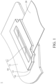
- FIG. 1 is a partial perspective view of a motherboard module 1 according to a first embodiment of the invention
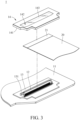
- FIG. 2 is an exploded view of the motherboard module 1 in FIG. 1 .
- the motherboard module 1 is applied to an electronic device, such as a notebook computer or a tablet computer.
- the motherboard module 1 includes a motherboard assembly 10 and an insertion piece 20.
- the motherboard assembly 10 includes a motherboard 11, an electrical connector 12, a first sealing component 13 and a second sealing component 14.
- the electrical connector 12 for example, mates with a flexible flat cable or a flexible printed circuit.
- the electrical connector 12 is disposed on the motherboard 11.
- the second sealing component 14 is, for example, made of a composite material containing a foam and a light-permeable sheet, and the second sealing component 14 and the first sealing component 13 have a same shape.
- the second sealing component 14 is disposed on the first sealing component 13, and the light permeable sheet thereof corresponds to the electrical connector 12.
- the second sealing component 14 includes an annular portion 141, a hollow portion 142 and a light permeable portion 143.
- the annular portion 141 is, for example, a part in the second sealing component 14 as the foam, and the annular portion 141 is fixed on the first sealing component 13 via, for example, adhering manner.
- the annular portion 141 surrounds the hollow portion 142, and the hollow portion 142 corresponds to the electrical connector 12.
- the insertion piece 20 is, for example, a flexible flat cable or a flexible printed circuit.
- the insertion piece 20 has an insertion portion 21 located at one end of the insertion piece 20, and another end of the insertion piece 20 is connected to another electronic component of the electronic device.
- the insertion portion 21 of the insertion piece 20 is inserted into the electrical connector 12, and the second sealing component 14 and the first sealing component 13 cover the electrical connector 12 and the insertion portion 21 of the insertion piece 20 together.
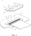
- FIGS. 3 and 4 show an assembling process of the motherboard module 1 in FIG. 1 .
- the first sealing component 13 is adhered on the motherboard 11, such that the first sealing component 13 surrounds the periphery of the electrical connector 12 on the motherboard 11.
- the insertion portion 21 of the insertion piece 20 is inserted into the electrical connector 12 of the motherboard 11.
- the annular portion 141 of the second sealing component 14 is adhered on the first sealing component 13, such that the first sealing component 13 and the second sealing component 14 cover the electrical connector 12 and the insertion portion 21 of the insertion piece 20 together (e.g., shown in FIG. 1 ).
- the assembly of the motherboard module 1 is finished.
- a user can remove the insertion piece 20 from the electrical connector 12 after the second sealing component 14 is tore off from the first sealing component 13.
- the first sealing component 13 is disposed on the motherboard 11 and located around the periphery of the electrical connector 12, and the second sealing component 14 is disposed on the first sealing component 13 for allowing the second sealing component 14 and the first sealing component 13 to cover the electrical connector 12 on the motherboard 11 and the insertion portion 21 of the insertion piece 20, which not only provides a waterproof effect to a place where the insertion portion 21 of the insertion piece 20 is inserted into the electrical connector 12, but also facilitates the removal of the insertion portion 21 of the insertion piece 20 from the electrical connector 12 on the motherboard 11 during the maintenance of the electronic device.
- the second sealing component 14 and the first sealing component 13 has the same shape, which facilitates the second sealing component 14 to be aligned with and adhered on the first sealing component 13.
- the second sealing component 14 and the first sealing component 13 are not restricted to having the same shape. In some other embodiments, the second sealing component and the first sealing component may have different shapes.
- the second sealing component 14 is provided with the hollow portion 142 corresponding to the electrical connector 12, and the hollow portion 142 is provided at the light permeable portion 143, which enables the user to observe the connection between the insertion portion 21 of the insertion piece 20 and the electrical connector 12 from the light permeable portion 143, thereby ensuring the insertion portion 21 of the insertion piece 20 to be inserted into the electrical connector 12 accurately.
- the hollow portion 142 and the light permeable portion 143 of the second sealing component 14 are optional structures.
- the second sealing component may not include the hollow portion and the light permeable portion; that is, the second sealing component visually blocks the electrical connector. As a result, before the second sealing component is adhered on the first sealing component, the insertion portion of the insertion piece need to be ensured to be accurately inserted into the electrical connector.
- the insertion portion 21 of the insertion piece 20 is inserted into the electrical connector 12a on the motherboard 11.
- the second sealing component 14 is adhered on the fixed part 1311a and the extension part 1312a of the first sealing component 13a, such that the first sealing component 13a and the second sealing component 14 together cover the electrical connector 12a and the insertion portion 21 of the insertion piece 20 (e.g., as shown in FIG. 5 ).
- the assembly of the motherboard module 1a is finished.
- one side of the electrical connector 12a is located close to the side surface 112 of the motherboard 11, and thus the annular portion 131a of the first sealing component 13a has the extension part 1312a which protrudes from the side surface 112 of the motherboard 11 for the second sealing component 14 to be adhered thereon, which ensures the periphery of the electrical connector 12a is covered by the first sealing component 13a and the second sealing component 14, thereby providing a waterproof effect to a place where the insertion portion 21 of the insertion piece 20 is inserted into the electrical connector 12a on the motherboard 11.
- the support portion 132a of the first sealing component 13a is located at one side of the extension part 1312a located farther away from the second sealing component 14; that is, the support portion 132a of the first sealing component 13a is located below the extension part 1312a for supporting the extension part 1312a and a part of the second sealing component 14.
- reverse folded portion 133a is bent along the profile of the support portion 132a and is fixed to the lower surface 113 of the motherboard 11, which can further strengthen the effect of supporting the extension part 1312a and a part of the second sealing component 14.
- the reverse folded portion 133a of the first sealing component 13 is an optional structure.
- the support portion of the first sealing component can sufficiently support the extension part and a part of the second sealing component, the first sealing component may not include the reverse folded portion.
- the support portion 132a of the first sealing component 13 is an optional structure.
- the first sealing component may not include the extension part.
- the first sealing component is disposed on the motherboard and located around the periphery of the electrical connector
- the second sealing component is disposed on the first sealing component for allowing the second sealing component and the first sealing component to cover the electrical connector on the motherboard and the insertion portion of the insertion piece, which not only provides a waterproof effect to a place where the insertion portion of the insertion piece is inserted into the electrical connector, but also facilitates the removal of the insertion portion of the insertion piece from the electrical connector on the motherboard during the maintenance of the electronic device.
- the second sealing component and the first sealing component has the same shape, which facilitates the second sealing component to be aligned with and adhered on the first sealing component.
- the second sealing component is provided with the hollow portion corresponding to the electrical connector, and the hollow portion is provided at the light permeable portion, which enable the user to observe the connection between the insertion portion of the insertion piece and the electrical connector from the light permeable portion, thereby ensuring the insertion portion of the insertion piece to be inserted into the electrical connector accurately.
Landscapes
- Engineering & Computer Science (AREA)
- Theoretical Computer Science (AREA)
- Manufacturing & Machinery (AREA)
- Computer Hardware Design (AREA)
- Power Engineering (AREA)
- Human Computer Interaction (AREA)
- Physics & Mathematics (AREA)
- General Engineering & Computer Science (AREA)
- General Physics & Mathematics (AREA)
- Microelectronics & Electronic Packaging (AREA)
- Connector Housings Or Holding Contact Members (AREA)
- Coupling Device And Connection With Printed Circuit (AREA)
Abstract
A motherboard module (1, 1a) includes a motherboard assembly (10) and an insertion piece (20). The motherboard assembly (10) includes a motherboard (11), an electrical connector (12, 12a), a first sealing component (13, 13a) and a second sealing component (14). The electrical connector (12, 12a) is disposed on the motherboard (11). The first sealing component (13, 13a) is disposed on the motherboard (11) and located around a periphery of the electrical connector (12, 12a). The second sealing component (14) is disposed on the first sealing component (13, 13a). The insertion piece (20) has an insertion portion (21). The insertion portion (21) is inserted into the electrical connector (12, 12a), and the second sealing component (14) and the first sealing component (13, 13a) cover the electrical connector (12, 12a) and the insertion portion (21) of the insertion piece (20) together.
Description
- The invention relates to a motherboard assembly, a motherboard module and an assembling method thereof.
- Currently, an electronic module in an electronic device (e.g., a desktop computer, a notebook computer and a server) is connected to a motherboard through a flexible cable. In order to prevent moisture from causing corrosion at a place where the flexible flat cable is connected to the motherboard and affecting signal transmission, a common solution is to apply a waterproof glue at the place where the flexible flat cable is connected to the motherboard. However, it is difficult to apply the waterproof glue at such place, and the waterproof glue may cause the maintenance of electronic device to be inconvenient. Therefore, how to address the aforementioned issues is one of the crucial topics in this field.
- The invention provides a motherboard assembly, a motherboard module and an assembling method thereof which can ensure the waterproof effect to the place where the flexible flat cable is connected to the motherboard while enabling the maintenance of electronic device to be convenient.
- One embodiment of the invention provides a motherboard module. The motherboard module includes a motherboard assembly and an insertion piece. The motherboard assembly includes a motherboard, an electrical connector, a first sealing component and a second sealing component. The electrical connector is disposed on the motherboard. The first sealing component is disposed on the motherboard and located around a periphery of the electrical connector. The second sealing component is disposed on the first sealing component. The insertion piece has an insertion portion. The insertion portion is inserted into the electrical connector, and the second sealing component and the first sealing component cover the electrical connector and the insertion portion of the insertion piece together.
- Another embodiment of the invention provides a motherboard assembly. The motherboard assembly is configured for insertion of an insertion piece. The motherboard assembly includes a motherboard, an electrical connector, a first sealing component and a second sealing component. The electrical connector is disposed on the motherboard and configured for insertion of an insertion portion of the insertion piece. The first sealing component is disposed on the motherboard and located around a periphery of the electrical connector. The second sealing component is disposed on the first sealing component. The second sealing component and the first sealing component are configured to cover the electrical connector and the insertion portion of the insertion piece together.
- Still another embodiment of the invention provides an assembling method of a motherboard module. The assembling method includes assembling a first sealing component on a motherboard to surround a periphery of an electrical connector disposed on the motherboard, inserting an insertion portion of an insertion piece into the electrical connector and assembling a second sealing component on the first sealing component to allow the second sealing component and the first sealing component cover the electrical connector and the insertion portion of the insertion piece together.
- According to the motherboard modules and the motherboard assemblies as discussed in the above embodiments, the first sealing component is disposed on the motherboard and located around the periphery of the electrical connector, and the second sealing component is disposed on the first sealing component for allowing the second sealing component and the first sealing component to cover the electrical connector on the motherboard and the insertion portion of the insertion piece, which not only provides a waterproof effect to a place where the insertion portion of the insertion piece is inserted into the electrical connector, but also facilitates the removal of the insertion portion of the insertion piece from the electrical connector on the motherboard during maintenance.
- The present invention will become better understood from the detailed description given herein below and the accompanying drawings which are given by way of illustration only and thus are not intending to limit the present invention and wherein:
-
FIG. 1 is a partial perspective view of a motherboard module according to a first embodiment of the invention; -
FIG. 2 is an exploded view of the motherboard module inFIG. 1 ; -
FIGS. 3 and4 show an assembling process of the motherboard module inFIG. 1 ; -
FIG. 5 is a partial perspective view of a motherboard module according to a second embodiment of the invention; -
FIG. 6 is an exploded view of the motherboard module inFIG. 5 ; -
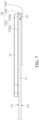
FIG. 7 is a side view of the motherboard module inFIG. 5 ; and -
FIGS. 8 to 10 show an assembling process of the motherboard module inFIG. 5 . - In the following detailed description, for purposes of explanation, numerous specific details are set forth in order to provide a thorough understanding of the disclosed embodiments. It will be apparent, however, that one or more embodiments may be practiced without these specific details. In other instances, well-known structures and devices are schematically shown in order to simplify the drawing.
- In addition, the terms used in the present invention, such as technical and scientific terms, have its own meanings and can be comprehended by those skilled in the art, unless the terms are additionally defined in the present invention. That is, the terms used in the following paragraphs should be read on the meaning commonly used in the related fields and will not be overly explained, unless the terms have a specific meaning in the present invention.
- Referring to
FIGS. 1 and2 ,FIG. 1 is a partial perspective view of amotherboard module 1 according to a first embodiment of the invention, andFIG. 2 is an exploded view of themotherboard module 1 inFIG. 1 . - In this embodiment, the
motherboard module 1 is applied to an electronic device, such as a notebook computer or a tablet computer. Themotherboard module 1 includes amotherboard assembly 10 and aninsertion piece 20. Themotherboard assembly 10 includes amotherboard 11, anelectrical connector 12, afirst sealing component 13 and asecond sealing component 14. - The
electrical connector 12, for example, mates with a flexible flat cable or a flexible printed circuit. Theelectrical connector 12 is disposed on themotherboard 11. - The
first sealing component 13 is, for example but not limited to, a foam. Thefirst sealing component 13 is in a ring shape and surrounds anaccommodation hole 131. Specifically, theaccommodation hole 131 is opened in thefirst sealing component 13. Thefirst sealing component 13 is fixed on themotherboard 11 via, for example, adhering manner, and theelectrical connector 12 is located in theaccommodation hole 131, such that thefirst sealing component 13 is located around a periphery of theelectrical connector 12. - The
second sealing component 14 is, for example, made of a composite material containing a foam and a light-permeable sheet, and thesecond sealing component 14 and thefirst sealing component 13 have a same shape. Thesecond sealing component 14 is disposed on thefirst sealing component 13, and the light permeable sheet thereof corresponds to theelectrical connector 12. Specifically, thesecond sealing component 14 includes anannular portion 141, ahollow portion 142 and a lightpermeable portion 143. Theannular portion 141 is, for example, a part in thesecond sealing component 14 as the foam, and theannular portion 141 is fixed on thefirst sealing component 13 via, for example, adhering manner. Theannular portion 141 surrounds thehollow portion 142, and thehollow portion 142 corresponds to theelectrical connector 12. The lightpermeable portion 143 is, for example, a part in thesecond sealing component 14 as the light permeable sheet, and the light permeable sheet is, for example, made of Mylar. The lightpermeable portion 143 is disposed on theannular portion 141 and seals thehollow portion 142. - The
insertion piece 20 is, for example, a flexible flat cable or a flexible printed circuit. Theinsertion piece 20 has aninsertion portion 21 located at one end of theinsertion piece 20, and another end of theinsertion piece 20 is connected to another electronic component of the electronic device. Theinsertion portion 21 of theinsertion piece 20 is inserted into theelectrical connector 12, and thesecond sealing component 14 and thefirst sealing component 13 cover theelectrical connector 12 and theinsertion portion 21 of theinsertion piece 20 together. - Then, the following descriptions will introduce an assembling process of the
motherboard module 1. Referring toFIGS. 3 and4 ,FIGS. 3 and4 show an assembling process of themotherboard module 1 inFIG. 1 . Firstly, as shown inFIG. 3 , thefirst sealing component 13 is adhered on themotherboard 11, such that thefirst sealing component 13 surrounds the periphery of theelectrical connector 12 on themotherboard 11. Then, as shown inFIG. 4 , theinsertion portion 21 of theinsertion piece 20 is inserted into theelectrical connector 12 of themotherboard 11. Then, theannular portion 141 of thesecond sealing component 14 is adhered on thefirst sealing component 13, such that thefirst sealing component 13 and thesecond sealing component 14 cover theelectrical connector 12 and theinsertion portion 21 of theinsertion piece 20 together (e.g., shown inFIG. 1 ). As a result, the assembly of themotherboard module 1 is finished. On the other hand, during the maintenance of the electronic device, a user can remove theinsertion piece 20 from theelectrical connector 12 after thesecond sealing component 14 is tore off from thefirst sealing component 13. - In this embodiment, the
first sealing component 13 is disposed on themotherboard 11 and located around the periphery of theelectrical connector 12, and thesecond sealing component 14 is disposed on thefirst sealing component 13 for allowing thesecond sealing component 14 and thefirst sealing component 13 to cover theelectrical connector 12 on themotherboard 11 and theinsertion portion 21 of theinsertion piece 20, which not only provides a waterproof effect to a place where theinsertion portion 21 of theinsertion piece 20 is inserted into theelectrical connector 12, but also facilitates the removal of theinsertion portion 21 of theinsertion piece 20 from theelectrical connector 12 on themotherboard 11 during the maintenance of the electronic device. - On the other hand, the
second sealing component 14 and thefirst sealing component 13 has the same shape, which facilitates thesecond sealing component 14 to be aligned with and adhered on thefirst sealing component 13. Note that thesecond sealing component 14 and thefirst sealing component 13 are not restricted to having the same shape. In some other embodiments, the second sealing component and the first sealing component may have different shapes. - Moreover, the
second sealing component 14 is provided with thehollow portion 142 corresponding to theelectrical connector 12, and thehollow portion 142 is provided at the lightpermeable portion 143, which enables the user to observe the connection between theinsertion portion 21 of theinsertion piece 20 and theelectrical connector 12 from the lightpermeable portion 143, thereby ensuring theinsertion portion 21 of theinsertion piece 20 to be inserted into theelectrical connector 12 accurately. - Note that the
hollow portion 142 and the lightpermeable portion 143 of thesecond sealing component 14 are optional structures. In some other embodiments, the second sealing component may not include the hollow portion and the light permeable portion; that is, the second sealing component visually blocks the electrical connector. As a result, before the second sealing component is adhered on the first sealing component, the insertion portion of the insertion piece need to be ensured to be accurately inserted into the electrical connector. - Then, referring to
FIGS. 5 to 7 ,FIG. 5 is a partial perspective view of a motherboard module 1a according to a second embodiment of the invention,FIG. 6 is an exploded view of the motherboard module 1a inFIG. 5 , andFIG. 7 is a side view of the motherboard module 1a inFIG. 5 . - The motherboard module 1a of this embodiment is similar to the
motherboard module 1 of the previous embodiment, and the main differences between them are the position of the electrical connector on the motherboard and the structure of the first sealing component. - In this embodiment, the motherboard module 1a includes a
motherboard assembly 10 and aninsertion piece 20. Themotherboard assembly 10 includes amotherboard 11, anelectrical connector 12a, afirst sealing component 13a and asecond sealing component 14. Themotherboard 11 has anupper surface 111, aside surface 112 and alower surface 113, and theupper surface 111, theside surface 112 and thelower surface 113 face different directions, respectively. Theupper surface 111 is connected to thelower surface 113 via theside surface 112, and thelower surface 113 faces away from theupper surface 111. Theelectrical connector 12a is disposed on theupper surface 111 of themotherboard 11, and one side of theelectrical connector 12a is located close to theside surface 112 of themotherboard 11. For example, one side of theelectrical connector 12a substantially abuts theside surface 112 of themotherboard 11. In other words, the side of theelectrical connector 12a is flush with theside surface 112 of themotherboard 11. - The
first sealing component 13a includes anannular portion 131a, asupport portion 132a and a reverse foldedportion 133a. Theannular portion 131a includes afixed part 1311a and anextension part 1312a connected to each other, and thefixed part 1311a and theextension part 1312a together form anaccommodation hole 1313a. Specifically, theaccommodation hole 1313a is opened in theannular portion 131a. Thefixed part 1311a is fixed on theupper surface 111 of themotherboard 11 via, for example, adhering manner. Theextension part 1312a protrudes from theside surface 112 of themotherboard 11. Theelectrical connector 12a on themotherboard 11 is located in the accommodation hole1313a so as to be surrounded by the fixedpart 1311a and theextension part 1312a together. Thesupport portion 132a is fixed to theextension part 1312a, and the reverse foldedportion 133a is connected to one side of theextension part 1312a located farther away from the fixedpart 1311a. The reverse foldedportion 133a is bent along a profile of thesupport portion 132a and is fixed to thelower surface 113 of themotherboard 11. - The
second sealing component 14 is adhered on thefixed part 1311a and theextension part 1312a of thefirst sealing component 13a. Thesecond sealing component 14 and thefixed part 1311a and theextension part 1312a of thefirst sealing component 13a together cover theelectrical connector 12a and theinsertion portion 21 of theinsertion piece 20 inserted into theelectrical connector 12a. - Then, the following descriptions will introduce an assembling method of the motherboard module 1a. Referring to
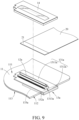
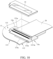
FIGS. 8 to 10, FIGS. 8 to 10 show an assembling process of the motherboard module 1a inFIG. 5 . Firstly, as shown inFIG. 8 , thefixed part 1311a of thefirst sealing component 13a is adhered on the uppers surface 111 of themotherboard 11, such that thefixed part 1311a and theextension part 1312a of thefirst sealing component 13a together surround the periphery of theelectrical connector 12a on themotherboard 11. Then, as shown inFIG. 9 , the reverse foldedportion 133a of thefirst sealing component 13a is bent along the profile of thesupport portion 132a and is adhered to thelower surface 113 of themotherboard 11. Then, as shown inFIG. 10 , theinsertion portion 21 of theinsertion piece 20 is inserted into theelectrical connector 12a on themotherboard 11. Then, thesecond sealing component 14 is adhered on thefixed part 1311a and theextension part 1312a of thefirst sealing component 13a, such that thefirst sealing component 13a and thesecond sealing component 14 together cover theelectrical connector 12a and theinsertion portion 21 of the insertion piece 20 (e.g., as shown inFIG. 5 ). As a result, the assembly of the motherboard module 1a is finished. - In this embodiment, one side of the
electrical connector 12a is located close to theside surface 112 of themotherboard 11, and thus theannular portion 131a of thefirst sealing component 13a has theextension part 1312a which protrudes from theside surface 112 of themotherboard 11 for thesecond sealing component 14 to be adhered thereon, which ensures the periphery of theelectrical connector 12a is covered by thefirst sealing component 13a and thesecond sealing component 14, thereby providing a waterproof effect to a place where theinsertion portion 21 of theinsertion piece 20 is inserted into theelectrical connector 12a on themotherboard 11. - Moreover, after the
second sealing component 14 is adhered on thefixed part 1311a and theextension part 1312a of thefirst sealing component 13a, thesupport portion 132a of thefirst sealing component 13a is located at one side of theextension part 1312a located farther away from thesecond sealing component 14; that is, thesupport portion 132a of thefirst sealing component 13a is located below theextension part 1312a for supporting theextension part 1312a and a part of thesecond sealing component 14. - In addition, the reverse folded
portion 133a is bent along the profile of thesupport portion 132a and is fixed to thelower surface 113 of themotherboard 11, which can further strengthen the effect of supporting theextension part 1312a and a part of thesecond sealing component 14. - Note that the reverse folded
portion 133a of thefirst sealing component 13 is an optional structure. When the support portion of the first sealing component can sufficiently support the extension part and a part of the second sealing component, the first sealing component may not include the reverse folded portion. Furthermore, thesupport portion 132a of thefirst sealing component 13 is an optional structure. When a rigidity of the extension part of the first sealing component is sufficient to support the second sealing component, the first sealing component may not include the extension part. - According to the motherboard modules and the motherboard assemblies as discussed in the above embodiments, the first sealing component is disposed on the motherboard and located around the periphery of the electrical connector, and the second sealing component is disposed on the first sealing component for allowing the second sealing component and the first sealing component to cover the electrical connector on the motherboard and the insertion portion of the insertion piece, which not only provides a waterproof effect to a place where the insertion portion of the insertion piece is inserted into the electrical connector, but also facilitates the removal of the insertion portion of the insertion piece from the electrical connector on the motherboard during the maintenance of the electronic device.
- On the other hand, the second sealing component and the first sealing component has the same shape, which facilitates the second sealing component to be aligned with and adhered on the first sealing component.
- Moreover, the second sealing component is provided with the hollow portion corresponding to the electrical connector, and the hollow portion is provided at the light permeable portion, which enable the user to observe the connection between the insertion portion of the insertion piece and the electrical connector from the light permeable portion, thereby ensuring the insertion portion of the insertion piece to be inserted into the electrical connector accurately.
- It will be apparent to those skilled in the art that various modifications and variations can be made to the present invention. It is intended that the specification and examples be considered as exemplary embodiments only, with a scope of the invention being indicated by the following claims and their equivalents.
Claims (15)
- A motherboard module (1, 1a), comprising:a motherboard assembly (10), comprising:a motherboard (11);an electrical connector (12, 12a), disposed on the motherboard (11);a first sealing component (13, 13a), disposed on the motherboard (11) and located around a periphery of the electrical connector (12, 12a); anda second sealing component (14), disposed on the first sealing component (13, 13a); andan insertion piece (20), having an insertion portion (21), wherein the insertion portion (21) is inserted into the electrical connector (12, 12a), and the second sealing component (14) and the first sealing component (13, 13a) cover the electrical connector (12, 12a) and the insertion portion (21) of the insertion piece (20) together.
- The motherboard module (1, 1a) according to claim 1, wherein the second sealing component (14) comprises an annular portion (141), a hollow portion (142) and a light permeable portion (143), the annular portion (141) is fixed to the first sealing component (13, 13a), the annular portion (141) surrounds the hollow portion (142), the hollow portion (142) corresponds to the electrical connector (12, 12a), and the light permeable portion (143) seals the hollow portion (142).
- The motherboard module (1a) according to claim 1, wherein the motherboard (11) has an upper surface (111) and a side surface (112), the upper surface (111) and the side surface (112) respectively face different directions, the electrical connector (12a) is disposed on the upper surface (111) of the motherboard (11), one side of the electrical connector (12a) is located close to the side surface (112) of the motherboard (11), the first sealing component (13a) comprises an annular portion (131a), the annular portion (131a) comprises a fixed part (1311a) and an extension part (1312a) connected to each other, the fixed part (1311a) is fixed to the upper surface (111) of the motherboard (11), the extension part (1312a) protrudes from the side surface (112) of the motherboard (11), and the fixed part (1311a) and the extension part (1312a) together surround the electrical connector (12a).
- The motherboard module (1a) according to claim 3, wherein the side of the electrical connector (12a) abuts the side surface (112) of the motherboard (11).
- The motherboard module (1a) according to claim 3, wherein the second sealing component (14) is adhered on the fixed part (1311a) and the extension part (1312a) of the annular portion (131a) of the first sealing component (13a).
- The motherboard module (1a) according to claim 5, wherein the first sealing component (13a) further comprises a support portion (132a), and the support portion (132a) is fixed on the extension part (1312a).
- The motherboard module (1a) according to claim 6, wherein the motherboard (11) further has a lower surface (113), the lower surface (113) faces away from the upper surface (111), the side surface (112) is connected to the lower surface (113) and the upper surface (111), the first sealing component (13a) further comprises a reverse folded portion (133a), the reverse folded portion (133a) is connected to one side of the extension part (1312a) located farther away from the fixed part (1311a), and the reverse folded portion (133a) is bent along the support portion (132a) and is fixed to the lower surface (113).
- A motherboard assembly (10), configured for insertion of an insertion piece (20), the motherboard assembly (10) comprising:a motherboard (11);an electrical connector (12, 12a), disposed on the motherboard (11) and configured for insertion of an insertion portion (21) of the insertion piece (20);a first sealing component (13, 13a), disposed on the motherboard (11) and located around a periphery of the electrical connector (12, 12a); anda second sealing component (14), disposed on the first sealing component (13, 13a), wherein the second sealing component (14) and the first sealing component (13, 13a) are configured to cover the electrical connector (12, 12a) and the insertion portion (21) of the insertion piece (20) together.
- The motherboard assembly (10) according to claim 8, wherein the second sealing component (14) comprises an annular portion (141), a hollow portion (142) and a light permeable portion (143), the annular portion (141) is fixed to the first sealing component (13, 13a), the annular portion (141) surrounds the hollow portion (142), the hollow portion (142) corresponds to the electrical connector (12, 12a), and the light permeable portion (143) seals the hollow portion (142).
- The motherboard assembly (10) according to claim 8, wherein the motherboard (11) has an upper surface (111) and a side surface (112), the upper surface (111) and the side surface (112) respectively face different directions, the electrical connector (12a) is disposed on the upper surface (111) of the motherboard (11), one side of the electrical connector (12a) is located close to the side surface (112) of the motherboard (11), the first sealing component (13a) comprises an annular portion (131a), the annular portion (131a) comprises a fixed part (1311a) and an extension part (1312a) connected to each other, the fixed part (1311a) is fixed to the upper surface (111) of the motherboard (11), the extension part (1312a) protrudes from the side surface (112) of the motherboard (11), and the fixed part (1311a) and the extension part (1312a) together surround the electrical connector (12a).
- The motherboard assembly (10) according to claim 10, wherein the side of the electrical connector (12a) abuts the side surface (112) of the motherboard (11).
- The motherboard assembly (10) according to claim 10, wherein the second sealing component (14) is adhered on the fixed part (1311a) and the extension part (1312a) of the annular portion (131a) of the first sealing component (13a).
- The motherboard assembly (10) according to claim 12, wherein the first sealing component (13a) further comprises a support portion (132a), and the support portion (132a) is fixed on the extension part (1312a).
- The motherboard assembly (10) according to claim 13, wherein the motherboard (11) further has a lower surface (113), the lower surface (113) faces away from the upper surface (111), the side surface (112) is connected to the lower surface (113) and the upper surface (111), the first sealing component (13a) further comprises a reverse folded portion (133a), the reverse folded portion (133a) is connected to one side of the extension part (1312a) located farther away from the fixed part (1311a), and the reverse folded portion (133a) is bent along the support portion (132a) and is fixed to the lower surface (113).
- An assembling method of a motherboard module (1, 1a), comprising:assembling a first sealing component (13, 13a) on a motherboard (11) to surround a periphery of an electrical connector (12, 12a) disposed on the motherboard (11);inserting an insertion portion (21) of an insertion piece (20) into the electrical connector (12, 12a); andassembling a second sealing component (14) on the first sealing component (13, 13a) to allow the second sealing component (14) and the first sealing component (13, 13a) cover the electrical connector (12, 12a) and the insertion portion (21) of the insertion piece (20) together.
Applications Claiming Priority (1)
| Application Number | Priority Date | Filing Date | Title |
|---|---|---|---|
| US202363545789P | 2023-10-26 | 2023-10-26 |
Publications (1)
| Publication Number | Publication Date |
|---|---|
| EP4546955A1 true EP4546955A1 (en) | 2025-04-30 |
Family
ID=91950251
Family Applications (1)
| Application Number | Title | Priority Date | Filing Date |
|---|---|---|---|
| EP24188653.0A Pending EP4546955A1 (en) | 2023-10-26 | 2024-07-15 | Motherboard assembly, motherboard module and assembling method thereof |
Country Status (4)
| Country | Link |
|---|---|
| US (1) | US20250141133A1 (en) |
| EP (1) | EP4546955A1 (en) |
| CN (1) | CN119905846A (en) |
| TW (1) | TWI876710B (en) |
Citations (5)
| Publication number | Priority date | Publication date | Assignee | Title |
|---|---|---|---|---|
| WO2005060100A1 (en) * | 2003-12-16 | 2005-06-30 | Pancomp Electronics Oy | Control and user interface for electronic device |
| US20070279877A1 (en) * | 2006-05-30 | 2007-12-06 | Stephan Dobritz | Circuit board arrangement |
| US20150085457A1 (en) * | 2013-09-20 | 2015-03-26 | Lotes Co., Ltd | Electrical connector and manufacturing method thereof |
| US20170373431A1 (en) * | 2016-06-22 | 2017-12-28 | Samsung Electronics Co., Ltd. | Sealed circuit board connectors and electronic device including same |
| US10985484B1 (en) * | 2018-10-01 | 2021-04-20 | Flex Ltd. | Electronic conductive interconnection for bridging across irregular areas in a textile product |
Family Cites Families (3)
| Publication number | Priority date | Publication date | Assignee | Title |
|---|---|---|---|---|
| TWM412507U (en) * | 2011-03-25 | 2011-09-21 | Advanced Connection Tech Inc | Electrical connector |
| CN102447195A (en) * | 2011-12-26 | 2012-05-09 | 广东步步高电子工业有限公司 | Waterproof method of BTB connector |
| CN210016026U (en) * | 2019-03-27 | 2020-02-04 | 上海绿联软件股份有限公司 | Packaging structure of electric connector, mainboard of white power product and white power product |
-
2023
- 2023-11-28 TW TW112145974A patent/TWI876710B/en active
- 2023-11-28 CN CN202311616186.9A patent/CN119905846A/en active Pending
-
2024
- 2024-06-03 US US18/731,463 patent/US20250141133A1/en active Pending
- 2024-07-15 EP EP24188653.0A patent/EP4546955A1/en active Pending
Patent Citations (5)
| Publication number | Priority date | Publication date | Assignee | Title |
|---|---|---|---|---|
| WO2005060100A1 (en) * | 2003-12-16 | 2005-06-30 | Pancomp Electronics Oy | Control and user interface for electronic device |
| US20070279877A1 (en) * | 2006-05-30 | 2007-12-06 | Stephan Dobritz | Circuit board arrangement |
| US20150085457A1 (en) * | 2013-09-20 | 2015-03-26 | Lotes Co., Ltd | Electrical connector and manufacturing method thereof |
| US20170373431A1 (en) * | 2016-06-22 | 2017-12-28 | Samsung Electronics Co., Ltd. | Sealed circuit board connectors and electronic device including same |
| US10985484B1 (en) * | 2018-10-01 | 2021-04-20 | Flex Ltd. | Electronic conductive interconnection for bridging across irregular areas in a textile product |
Also Published As
| Publication number | Publication date |
|---|---|
| CN119905846A (en) | 2025-04-29 |
| TW202518210A (en) | 2025-05-01 |
| TWI876710B (en) | 2025-03-11 |
| US20250141133A1 (en) | 2025-05-01 |
Similar Documents
| Publication | Publication Date | Title |
|---|---|---|
| US11058000B1 (en) | Flexible display device | |
| US20030008566A1 (en) | Connector for plural mating connectiors having different shapes of interfaces | |
| EP3255963A1 (en) | Electronic apparatus | |
| US20050185365A1 (en) | Display apparatus | |
| CN104967707A (en) | Mobile device | |
| EP2712470B1 (en) | Usb connector having vertical to horizontal conversion contacts | |
| JPH03151695A (en) | Supporting device of planer board and its supporting method | |
| US20250141133A1 (en) | Motherboard assembly, motherboard module and assembling method thereof | |
| CN105792506A (en) | FPC, FPC connector and FPC connecting device | |
| US9184521B2 (en) | Connector assembly and electronic device | |
| KR101402931B1 (en) | Methode for Flexible Printed Circuit Board Process with Vaccum Zig System | |
| US9244488B2 (en) | Display device | |
| CN104509225B (en) | Bracket assembly structure | |
| US8525046B2 (en) | Electronic apparatus | |
| US20070238352A1 (en) | Electrical connector | |
| CN106060734A (en) | FPCB structure, loudspeaker module and manufacturing method of FPCB | |
| CN215681015U (en) | Module structure and electronic equipment | |
| CN209267872U (en) | A kind of wiring construction controlling box | |
| US20240405463A1 (en) | Connector and electronic device including same | |
| JP3301529B2 (en) | Optical cable extra length processing device | |
| EP4071547B1 (en) | Display device | |
| WO2025187523A1 (en) | Electronic device | |
| CN202838862U (en) | Display module and fixing mechanism thereof | |
| TWI521806B (en) | Connector assembly and electronic device | |
| JPH10161557A (en) | Display device |
Legal Events
| Date | Code | Title | Description |
|---|---|---|---|
| PUAI | Public reference made under article 153(3) epc to a published international application that has entered the european phase |
Free format text: ORIGINAL CODE: 0009012 |
|
| STAA | Information on the status of an ep patent application or granted ep patent |
Free format text: STATUS: THE APPLICATION HAS BEEN PUBLISHED |
|
| AK | Designated contracting states |
Kind code of ref document: A1 Designated state(s): AL AT BE BG CH CY CZ DE DK EE ES FI FR GB GR HR HU IE IS IT LI LT LU LV MC ME MK MT NL NO PL PT RO RS SE SI SK SM TR |
|
| STAA | Information on the status of an ep patent application or granted ep patent |
Free format text: STATUS: REQUEST FOR EXAMINATION WAS MADE |
|
| 17P | Request for examination filed |
Effective date: 20250514 |