EP4546951A1 - Acceleration cavity - Google Patents
Acceleration cavity Download PDFInfo
- Publication number
- EP4546951A1 EP4546951A1 EP23850026.8A EP23850026A EP4546951A1 EP 4546951 A1 EP4546951 A1 EP 4546951A1 EP 23850026 A EP23850026 A EP 23850026A EP 4546951 A1 EP4546951 A1 EP 4546951A1
- Authority
- EP
- European Patent Office
- Prior art keywords
- housing
- vacuum manifold
- accelerating cavity
- cell portions
- central axis
- Prior art date
- Legal status (The legal status is an assumption and is not a legal conclusion. Google has not performed a legal analysis and makes no representation as to the accuracy of the status listed.)
- Pending
Links
Images





Classifications
-
- H—ELECTRICITY
- H05—ELECTRIC TECHNIQUES NOT OTHERWISE PROVIDED FOR
- H05H—PLASMA TECHNIQUE; PRODUCTION OF ACCELERATED ELECTRICALLY-CHARGED PARTICLES OR OF NEUTRONS; PRODUCTION OR ACCELERATION OF NEUTRAL MOLECULAR OR ATOMIC BEAMS
- H05H7/00—Details of devices of the types covered by groups H05H9/00, H05H11/00, H05H13/00
- H05H7/14—Vacuum chambers
- H05H7/18—Cavities; Resonators
- H05H7/20—Cavities; Resonators with superconductive walls
-
- H—ELECTRICITY
- H05—ELECTRIC TECHNIQUES NOT OTHERWISE PROVIDED FOR
- H05H—PLASMA TECHNIQUE; PRODUCTION OF ACCELERATED ELECTRICALLY-CHARGED PARTICLES OR OF NEUTRONS; PRODUCTION OR ACCELERATION OF NEUTRAL MOLECULAR OR ATOMIC BEAMS
- H05H9/00—Linear accelerators
- H05H9/04—Standing-wave linear accelerators
- H05H9/041—Hadron LINACS
- H05H9/042—Drift tube LINACS
-
- H—ELECTRICITY
- H05—ELECTRIC TECHNIQUES NOT OTHERWISE PROVIDED FOR
- H05H—PLASMA TECHNIQUE; PRODUCTION OF ACCELERATED ELECTRICALLY-CHARGED PARTICLES OR OF NEUTRONS; PRODUCTION OR ACCELERATION OF NEUTRAL MOLECULAR OR ATOMIC BEAMS
- H05H9/00—Linear accelerators
- H05H9/04—Standing-wave linear accelerators
- H05H9/048—Lepton LINACS
Definitions
- the present disclosure relates to an accelerating cavity.
- an accelerating cavity that includes forming a plurality of divided members divided on a dividing surface formed on a plane taken along a central axis in advance and joining the divided members on the dividing surface in a case where the accelerating cavity described above is manufactured has been proposed.
- a configuration for efficiently evacuating the inside of the accelerating cavity is required.
- the present disclosure has been made in view of the above circumstances, and an object of the present disclosure is to provide an accelerating cavity of which the inside can be efficiently evacuated.
- An accelerating cavity includes a housing that has conductivity and a tubular shape and in which a plurality of divided members divided on planar dividing surfaces taken along a central axis are provided in a state where the dividing surfaces along the plane face each other with a gap therebetween, a plurality of cell portions that are arranged in the housing in a state of being lined up in an axial direction of the central axis of the housing and communicate with each other via communication portions through which charged particles are capable of passing, and a vacuum manifold that is connected to the plurality of cell portions via the gap.
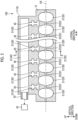
- Fig. 1 is a plan view showing an example of an accelerating cavity 100 according to a first embodiment.
- Fig. 2 is a diagram showing a configuration taken along a cross section taken along line A-A of Fig. 1 . Although being not a cross section, a dividing surface 12 is shown with hatching in Fig. 2 .
- Fig. 3 is a diagram showing a configuration taken along a cross section taken along line B-B of Fig. 2 .
- the accelerating cavity 100 shown in Figs. 1 to 3 generates accelerating electric fields therein in a case where high-frequency waves are input to the accelerating cavity 100, and accelerates charged particles M such as electrons emitted from a beam source BS.
- An accelerator AC is formed using the accelerating cavity 100 and the beam source BS.
- the accelerator AC is used in various fields, such as an academic field such as a high-energy physics experiment and a synchrotron radiation facility, a medical field such as radiation therapy and radiographic examination, and an industrial field such as non-destructive inspection.
- the housing 10 has conductivity and a tubular shape.
- the housing 10 is formed in a state where a plurality of divided members 11 are joined to each other.
- the divided member 11 has a planar dividing surface 12 taken along the central axis AX.
- the respective divided members 11 are joined to each other in a state where the dividing surfaces 12 face each other.
- the respective divided members 11 are provided in a state where a gap 13 is provided between the dividing surfaces 12 facing each other.
- a configuration in which the housing 10 is divided in a lateral direction of the central axis AX along a plane orthogonal to a horizontal plane and passing through the central axis AX will be described as an example.
- the number of divisions of the housing 10 is not limited to two and may be three or more. Portions of the divided members 11 facing each other have a rounded shape as a whole. For this reason, the local application of a voltage is suppressed.
- the cell portions 20 are formed in the housing 10.
- the cell portions 20 are arranged in a state of being lined up in the axial direction of the central axis AX of the housing 10.
- the cell portions 20 communicate with each other via communication portions 22 through which charged particles pass.
- the communication portions 22 are formed along the central axis AX.
- the cell portions 20 accelerate charged particles with high-frequency waves.
- the coupling cavity 30 connects the adjacent cell portions 20.
- the coupling cavity 30 propagates high-frequency waves between the adjacent cell portions 20.
- the coupling cavities 30 are disposed at portions that do not contribute to the acceleration of charged particles.
- the coupling cavities 30 are disposed outside the cell portions 20 in the same direction among directions orthogonal to the central axis AX. In the first embodiment, all the coupling cavities 30 are disposed above the cell portions 20 with respect to the central axis AX as a reference.
- the vacuum manifold 40 is a portion that forms negative pressure in a case where the plurality of cell portions 20 are evacuated.
- the vacuum manifold 40 is connected to a vacuum forming unit 42, such as a vacuum pump, via a pipe 43.
- the vacuum manifold 40 is provided, for example, in the housing 10.
- the vacuum manifold 40 is formed as one space and is disposed above the respective coupling cavities 30.
- the vacuum manifold 40 is connected to the plurality of cell portions 20 via the gap 13 between the divided members 11.
- the respective cell portions 20 are connected to one vacuum manifold 40.
- the vacuum manifold 40 communicates with the coupling cavities 30 via the communication portions 45. Therefore, the vacuum manifold 40 is connected to the plurality of cell portions 20 via the respective coupling cavities 30. With this configuration, the vacuum manifold 40 and the plurality of cell portions 20 are reliably connected to each other.
- unit cell portions 21 and unit communication portions 23 that form a part of the cell portions 20 and the communication portions 22, unit coupling cavities 31 that form a part of the coupling cavities 30, and a unit manifold 41 that forms a part of the vacuum manifold 40 are formed on the dividing surface 12 of each divided member 11 in the housing 10.
- the unit cell portions 21 provided in the respective divided members 11 are combined to form the cell portions 20.
- the unit communication portions 24 provided in the respective divided members 11 are combined to form the communication portions 22.
- the unit coupling cavities 31 provided in the respective divided members 11 are combined to form the coupling cavities 30.
- the unit manifolds 41 formed in the respective divided members 11 are combined to form the vacuum manifold 40.
- the accelerating cavity 100 includes the housing 10 which has conductivity and a tubular shape and in which the plurality of divided members 11 divided on a plane taken along the central axis AX are provided in a state where the dividing surfaces 12 along the plane face each other with the gap 13 therebetween, the plurality of cell portions 20 that are arranged in the housing 10 in a state of being lined up in the axial direction of the central axis AX of the housing 10 and communicate with each other via the communication portions 22 through which charged particles can pass, and the vacuum manifold 40 that is connected to the plurality of cell portions 20 via the gap 13.
- the vacuum manifold 40 is connected to the plurality of cell portions 20 via the gap 13. Therefore, the inside of the cell portions 20 can be efficiently evacuated.
- the vacuum manifold 40 is connected to the gap 13 of the housing 10 in a direction orthogonal to the central axis AX. According to this configuration, the vacuum manifold 40 can be disposed in the housing 10 in the direction orthogonal to the central axis AX.
- all the coupling cavities 30 are arranged on the same side of the cell portions 20 in the direction orthogonal to the central axis AX. Since the coupling cavities 30 are arranged on the same side of the cell portions 20 in the direction orthogonal to the central axis AX to be close to the cell portions 20 in this configuration, directions of electric fields in the direction (vertical direction) orthogonal to the central axis AX are opposite to each other in two coupling cavities 30 connected to one cell portion 20. Accordingly, since the electric fields in the vertical direction cancel out, the shift of the center of the electric field distribution in the cell portion 20 in the vertical direction can be suppressed. For this reason, the bias of a beam of charged particles can be suppressed.
- the accelerating cavity 100 further includes coupling cavities 30 which are provided in the housing 10 and each of which connects the adjacent cell portions 20, and the coupling cavities 30 are connected to the vacuum manifold 40. According to this configuration, since the vacuum manifold 40 is connected to the cell portions 20 via the coupling cavities 30, the cell portions 20 can be more reliably evacuated by the vacuum manifold 40.
- the vacuum manifold 40 is provided in the housing 10. Since the vacuum manifold 40 is provided in the housing 10 in this configuration, the number of components can be reduced.
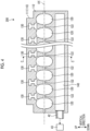
- FIG. 4 is a cross-sectional view showing an example of an accelerating cavity 200 according to a second embodiment. Although being not a cross section, a dividing surface 112 is shown with hatching in Fig. 4 .
- Fig. 5 is a diagram showing a configuration taken along a cross section taken along line C-C of Fig. 4 .
- the accelerating cavity 200 includes a housing 110, cell portions 120, coupling cavities 130, and a vacuum manifold 140.
- the housing 110 is formed in a state where a plurality of divided members 111 are joined to each other.
- the respective divided members 111 are joined to each other in a state where dividing surfaces 112 face each other, and are provided in a state where a gap 113 is provided between the dividing surfaces 112 facing each other.
- the plurality of cell portions 120 are formed in the housing 110 in a state of being lined up in an axial direction of a central axis AX, and communicate with each other via communication portions 122.
- unit cell portions and unit communication portions that form a part of the cell portions 120 and the communication portions 122, unit coupling cavities that form a part of the coupling cavities 130, and a unit manifold that forms a part of the vacuum manifold 140 are formed on the dividing surface 112 of each divided member 111 in the housing 110 as in the first embodiment.
- the coupling cavities 130 and the vacuum manifold 140 are disposed on opposite sides of the cell portions 120 in a direction orthogonal to the central axis AX. That is, the coupling cavities 130 are arranged on one side of the cell portions 120 in the direction orthogonal to the central axis AX, and the vacuum manifold 140 is disposed on the other side opposite to the one side of the cell portions 120. In the example shown in Fig. 4 , the coupling cavities 130 are arranged on an upper side of the cell portions 120, and the vacuum manifold 140 is disposed on a lower side of the cell portions 120.
- the vacuum manifold 140 and the cell portions 120 are connected to each other via the gap 113. Therefore, the cell portions 120 can be evacuated via the gap 113 by the vacuum manifold 140. For this reason, the cell portions 120 can be efficiently evacuated.
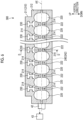
- Fig. 6 is a cross-sectional view showing an example of an accelerating cavity 300 according to a third embodiment. Although being not a cross section, a dividing surface 212 is shown with hatching in Fig. 6 .
- Fig. 7 is a diagram showing a configuration taken along a cross section taken along line D-D of Fig. 6 .
- the accelerating cavity 300 includes a housing 210, cell portions 220, coupling cavities 230, and a vacuum manifold 240.
- the housing 210 is formed in a state where a plurality of divided members 211 are joined to each other.
- the respective divided members 211 are joined to each other in a state where the dividing surfaces 212 face each other, and are provided in a state where a gap 213 is provided between the dividing surfaces 212 facing each other.
- the gap 213 is sealed by welding, adhesion, a seal member, or the like at a portion excluding the vacuum manifold 240 provided outside the housing 210 and communication portions 222.
- the plurality of cell portions 220 are formed in the housing 210 in a state of being lined up in an axial direction of a central axis AX, and communicate with each other via the communication portions 222.
- unit cell portions and unit communication portions that form a part of the cell portions 220 and the communication portions 222, unit coupling cavities that form a part of the coupling cavities 230, and a unit manifold that forms a part of the vacuum manifold 240 are formed on the dividing surface 212 of each divided member 211 in the housing 210 as in each embodiment described above.
- the vacuum manifold 240 is provided outside the housing 210 in the accelerating cavity 300 according to the third embodiment. That is, the vacuum manifold 240 and the housing 210 are provided as separate components. With this configuration, the degree of freedom of the disposition of the vacuum manifold 240 is increased.
- the vacuum manifold 240 is provided in a manifold forming member 242 disposed on a lateral side of the housing 210 in the axial direction of the central axis AX.
- the manifold forming member 242 has, for example, an arc-shaped cross section as shown in Fig. 7 , but is not limited to this configuration.
- the manifold forming member 242 may have other shapes such as a rectangular shape or a triangular shape.
- the housing 210 includes exhaust holes 214.
- the exhaust holes 214 are disposed in the housing 210 at positions away from each cell portion 220.
- the exhaust holes 214 are formed in a direction intersecting the dividing surface 212.
- the exhaust holes 214 communicate with the gap 213 and the vacuum manifold 240.
- Fig. 8 is a cross-sectional view showing another example of the accelerating cavity according to the third embodiment. Although being not a cross section, a dividing surface 212 is shown with hatching in Fig. 8 .
- Fig. 9 is a diagram showing a configuration taken along a cross section taken along line E-E of Fig. 8 .
- the configuration of an accelerating cavity 300A shown in Figs. 8 and 9 is different from the configuration of the accelerating cavity 300A in that a vacuum manifold 240A (manifold forming member 242A) is disposed under the housing 210. In this configuration, the vacuum manifold 240A is connected to the cell portions 220 via the gap 213.
- a vacuum manifold 240A manifold forming member 242A
- the vacuum manifold 240 is provided outside the housing 210. With this configuration, the degree of freedom of the disposition of the vacuum manifold 240 is increased.
- the housing 210 includes the exhaust holes 214 that are formed in a direction intersecting the dividing surface 212 at positions away from the plurality of cell portions 220 and communicate with the gap 213 and the vacuum manifold 240 provided outside the housing 210.
- the cell portions 220 can be efficiently evacuated via the exhaust holes 214 by the vacuum manifold 240.
- an accelerating cavity includes a housing 10 which has conductivity and a tubular shape and in which a plurality of divided members 11 divided on a plane taken along a central axis AX are provided in a state where dividing surfaces 12 along the plane face each other with a gap 13 therebetween, a plurality of cell portions 20 that are arranged in the housing 10 in a state of being lined up in an axial direction of the central axis AX of the housing 10 and communicate with each other via communication portions 22 through which charged particles are capable of passing, and a vacuum manifold 40 that is connected to the plurality of cell portions 20 via the gap 13.
- the vacuum manifold 40 is connected to the plurality of cell portions 20 via the gap 13. Therefore, the inside of the cell portions 20 can be efficiently evacuated.
- the vacuum manifold 40 is connected to the gap 13 of the housing 10 in a direction orthogonal to the central axis AX.
- the vacuum manifold 40 can be disposed in the housing 10 in the direction orthogonal to the central axis AX.
- the accelerating cavity according to the first or second aspect further includes coupling cavities 30 which are provided in the housing 10 and each of which connects the adjacent cell portions 20, and all the coupling cavities 30 are arranged on the same side of the cell portions 20 in a direction orthogonal to the central axis AX.
- the coupling cavities 30 are arranged on the same side of the cell portions 20 in the direction orthogonal to the central axis AX to be close to the cell portions 20 in this configuration, the center of the electric field distribution in the direction orthogonal to the central axis AX can be aligned with the central axis AX. For this reason, the bias of a beam of charged particles can be suppressed.
- the coupling cavities 30 are connected to the vacuum manifold 40.
- the vacuum manifold 40 is connected to the cell portions 20 via the coupling cavities 30, the cell portions 20 can be more reliably evacuated by the vacuum manifold 40.
- the coupling cavities 130 and the vacuum manifold 140 are disposed on opposite sides of the cell portions 120 in the direction orthogonal to the central axis AX.
- the vacuum manifold 140 and the cell portions 120 are connected to each other via the gap 113. Therefore, the cell portions 120 can be evacuated via the gap 113 by the vacuum manifold 140. For this reason, the cell portions 120 can be efficiently evacuated.
- the vacuum manifold 40 is provided in the housing 10.
- the vacuum manifold 40 is provided in the housing 10 in this configuration, the number of components can be reduced.
- the vacuum manifold 240 is provided outside the housing 210.
- the housing 210 includes exhaust holes 214 that are formed in a direction intersecting the dividing surface 212 at positions away from the plurality of cell portions 220 and communicate with the gap 213 and the vacuum manifold 240 provided outside the housing 210.
- the cell portions 220 can be efficiently evacuated via the exhaust holes 214 by the vacuum manifold 240.
Landscapes
- Physics & Mathematics (AREA)
- Engineering & Computer Science (AREA)
- Plasma & Fusion (AREA)
- Spectroscopy & Molecular Physics (AREA)
- Particle Accelerators (AREA)
Abstract
Description
- The present disclosure relates to an accelerating cavity.
- An accelerating cavity generates accelerating electric fields therein in a case where high-frequency waves are input to the accelerating cavity, and accelerates charged particles such as electrons. As such an accelerating cavity, a configuration is known in which, for example, a plurality of cell portions lined up in an axial direction of a central axis are provided and the cell portions communicate with each other via communication portions (see, for example, PTL 1).
- [PTL 1]
Japanese Unexamined Patent Application Publication No. H01-107499 - In recent years, a method of forming an accelerating cavity that includes forming a plurality of divided members divided on a dividing surface formed on a plane taken along a central axis in advance and joining the divided members on the dividing surface in a case where the accelerating cavity described above is manufactured has been proposed. In the accelerating cavity manufactured by such a method, a configuration for efficiently evacuating the inside of the accelerating cavity is required.
- The present disclosure has been made in view of the above circumstances, and an object of the present disclosure is to provide an accelerating cavity of which the inside can be efficiently evacuated.
- An accelerating cavity according to the present disclosure includes a housing that has conductivity and a tubular shape and in which a plurality of divided members divided on planar dividing surfaces taken along a central axis are provided in a state where the dividing surfaces along the plane face each other with a gap therebetween, a plurality of cell portions that are arranged in the housing in a state of being lined up in an axial direction of the central axis of the housing and communicate with each other via communication portions through which charged particles are capable of passing, and a vacuum manifold that is connected to the plurality of cell portions via the gap.
- According to the present disclosure, it is possible to provide an accelerating cavity of which the inside can be efficiently evacuated.
-
-
Fig. 1 is a plan view showing an example of an accelerating cavity according to a first embodiment. -
Fig. 2 is a diagram showing a configuration taken along a cross section taken along line A-A ofFig. 1 . -
Fig. 3 is a diagram showing a configuration taken along a cross section taken along line B-B ofFig. 2 . -
Fig. 4 is a cross-sectional view showing an example of an accelerating cavity according to a second embodiment. -
Fig. 5 is a diagram showing a configuration taken along a cross section taken along line C-C ofFig. 4 . -
Fig. 6 is a cross-sectional view showing an example of an accelerating cavity according to a third embodiment. -
Fig. 7 is a diagram showing a configuration taken along a cross section taken along line D-D ofFig. 6 . -
Fig. 8 is a cross-sectional view showing another example of the accelerating cavity according to the third embodiment. -
Fig. 9 is a diagram showing a configuration taken along a cross section taken along line E-E ofFig. 8 . - Accelerating cavities according to embodiments of the present disclosure will be described below with reference to the drawings. The present invention is not limited by the embodiments. Further, components of the following embodiments include components that can be easily substituted by those skilled in the art or components that are substantially the same as the components of the following embodiments.
-
Fig. 1 is a plan view showing an example of an acceleratingcavity 100 according to a first embodiment.Fig. 2 is a diagram showing a configuration taken along a cross section taken along line A-A ofFig. 1 . Although being not a cross section, a dividingsurface 12 is shown with hatching inFig. 2 .Fig. 3 is a diagram showing a configuration taken along a cross section taken along line B-B ofFig. 2 . - The accelerating
cavity 100 shown inFigs. 1 to 3 generates accelerating electric fields therein in a case where high-frequency waves are input to the acceleratingcavity 100, and accelerates charged particles M such as electrons emitted from a beam source BS. An accelerator AC is formed using the acceleratingcavity 100 and the beam source BS. The accelerator AC is used in various fields, such as an academic field such as a high-energy physics experiment and a synchrotron radiation facility, a medical field such as radiation therapy and radiographic examination, and an industrial field such as non-destructive inspection. In the following description, in a case where an axial direction of a central axis AX is described among directions of the acceleratingcavity 100, a side facing the beam source BS (a side from which charged particles M are incident) is referred to as an incident side and a side opposite to the incident side (a side from which the charged particles are emitted) is referred to as an emission side. - As shown in
Figs. 1 to 3 , the acceleratingcavity 100 according to the present embodiment includes ahousing 10,cell portions 20,coupling cavities 30, and avacuum manifold 40. - The
housing 10 has conductivity and a tubular shape. Thehousing 10 is formed in a state where a plurality of dividedmembers 11 are joined to each other. The dividedmember 11 has a planar dividingsurface 12 taken along the central axis AX. The respective dividedmembers 11 are joined to each other in a state where the dividingsurfaces 12 face each other. The respective dividedmembers 11 are provided in a state where agap 13 is provided between the dividingsurfaces 12 facing each other. In the present embodiment, a configuration in which thehousing 10 is divided in a lateral direction of the central axis AX along a plane orthogonal to a horizontal plane and passing through the central axis AX will be described as an example. The number of divisions of thehousing 10 is not limited to two and may be three or more. Portions of the dividedmembers 11 facing each other have a rounded shape as a whole. For this reason, the local application of a voltage is suppressed. - The
cell portions 20 are formed in thehousing 10. Thecell portions 20 are arranged in a state of being lined up in the axial direction of the central axis AX of thehousing 10. Thecell portions 20 communicate with each other viacommunication portions 22 through which charged particles pass. Thecommunication portions 22 are formed along the central axis AX. Thecell portions 20 accelerate charged particles with high-frequency waves. - The
coupling cavity 30 connects theadjacent cell portions 20. Thecoupling cavity 30 propagates high-frequency waves between theadjacent cell portions 20. Thecoupling cavities 30 are disposed at portions that do not contribute to the acceleration of charged particles. Thecoupling cavities 30 are disposed outside thecell portions 20 in the same direction among directions orthogonal to the central axis AX. In the first embodiment, all thecoupling cavities 30 are disposed above thecell portions 20 with respect to the central axis AX as a reference. - The
vacuum manifold 40 is a portion that forms negative pressure in a case where the plurality ofcell portions 20 are evacuated. Thevacuum manifold 40 is connected to avacuum forming unit 42, such as a vacuum pump, via apipe 43. In the present embodiment, thevacuum manifold 40 is provided, for example, in thehousing 10. Thevacuum manifold 40 is formed as one space and is disposed above therespective coupling cavities 30. Thevacuum manifold 40 is connected to the plurality ofcell portions 20 via thegap 13 between the dividedmembers 11. Therespective cell portions 20 are connected to onevacuum manifold 40. Further, in the present embodiment, thevacuum manifold 40 communicates with thecoupling cavities 30 via thecommunication portions 45. Therefore, thevacuum manifold 40 is connected to the plurality ofcell portions 20 via therespective coupling cavities 30. With this configuration, thevacuum manifold 40 and the plurality ofcell portions 20 are reliably connected to each other. - As shown in
Fig. 2 ,unit cell portions 21 andunit communication portions 23 that form a part of thecell portions 20 and thecommunication portions 22,unit coupling cavities 31 that form a part of thecoupling cavities 30, and aunit manifold 41 that forms a part of thevacuum manifold 40 are formed on the dividingsurface 12 of each dividedmember 11 in thehousing 10. - The
unit cell portions 21 provided in the respective dividedmembers 11 are combined to form thecell portions 20. The unit communication portions 24 provided in the respective dividedmembers 11 are combined to form thecommunication portions 22. Theunit coupling cavities 31 provided in the respective dividedmembers 11 are combined to form thecoupling cavities 30. The unit manifolds 41 formed in the respective dividedmembers 11 are combined to form thevacuum manifold 40. - The accelerating
cavity 100 according to the present embodiment includes thehousing 10 which has conductivity and a tubular shape and in which the plurality of dividedmembers 11 divided on a plane taken along the central axis AX are provided in a state where the dividing surfaces 12 along the plane face each other with thegap 13 therebetween, the plurality ofcell portions 20 that are arranged in thehousing 10 in a state of being lined up in the axial direction of the central axis AX of thehousing 10 and communicate with each other via thecommunication portions 22 through which charged particles can pass, and thevacuum manifold 40 that is connected to the plurality ofcell portions 20 via thegap 13. - According to this configuration, in a configuration in which the
housing 10 is provided in a state where the dividing surfaces 12 of the plurality of dividedmembers 11 face each other with thegap 13 therebetween, thevacuum manifold 40 is connected to the plurality ofcell portions 20 via thegap 13. Therefore, the inside of thecell portions 20 can be efficiently evacuated. - In the accelerating
cavity 100 according to the present embodiment, thevacuum manifold 40 is connected to thegap 13 of thehousing 10 in a direction orthogonal to the central axis AX. According to this configuration, thevacuum manifold 40 can be disposed in thehousing 10 in the direction orthogonal to the central axis AX. - In the accelerating
cavity 100 according to the present embodiment, all thecoupling cavities 30 are arranged on the same side of thecell portions 20 in the direction orthogonal to the central axis AX. Since thecoupling cavities 30 are arranged on the same side of thecell portions 20 in the direction orthogonal to the central axis AX to be close to thecell portions 20 in this configuration, directions of electric fields in the direction (vertical direction) orthogonal to the central axis AX are opposite to each other in twocoupling cavities 30 connected to onecell portion 20. Accordingly, since the electric fields in the vertical direction cancel out, the shift of the center of the electric field distribution in thecell portion 20 in the vertical direction can be suppressed. For this reason, the bias of a beam of charged particles can be suppressed. - The accelerating
cavity 100 according to the present embodiment further includescoupling cavities 30 which are provided in thehousing 10 and each of which connects theadjacent cell portions 20, and thecoupling cavities 30 are connected to thevacuum manifold 40. According to this configuration, since thevacuum manifold 40 is connected to thecell portions 20 via thecoupling cavities 30, thecell portions 20 can be more reliably evacuated by thevacuum manifold 40. - In the accelerating
cavity 100 according to the present embodiment, thevacuum manifold 40 is provided in thehousing 10. Since thevacuum manifold 40 is provided in thehousing 10 in this configuration, the number of components can be reduced. - Next, a second embodiment will be described.
Fig. 4 is a cross-sectional view showing an example of an acceleratingcavity 200 according to a second embodiment. Although being not a cross section, a dividingsurface 112 is shown with hatching inFig. 4 .Fig. 5 is a diagram showing a configuration taken along a cross section taken along line C-C ofFig. 4 . - As shown in
Figs. 4 and5 , the acceleratingcavity 200 according to the second embodiment includes ahousing 110,cell portions 120,coupling cavities 130, and avacuum manifold 140. Thehousing 110 is formed in a state where a plurality of dividedmembers 111 are joined to each other. The respective dividedmembers 111 are joined to each other in a state where dividingsurfaces 112 face each other, and are provided in a state where agap 113 is provided between the dividingsurfaces 112 facing each other. The plurality ofcell portions 120 are formed in thehousing 110 in a state of being lined up in an axial direction of a central axis AX, and communicate with each other viacommunication portions 122. Although reference numerals are omitted in the acceleratingcavity 200 according to the second embodiment, unit cell portions and unit communication portions that form a part of thecell portions 120 and thecommunication portions 122, unit coupling cavities that form a part of thecoupling cavities 130, and a unit manifold that forms a part of thevacuum manifold 140 are formed on the dividingsurface 112 of each dividedmember 111 in thehousing 110 as in the first embodiment. - In the accelerating
cavity 200 according to the present embodiment, thecoupling cavities 130 and thevacuum manifold 140 are disposed on opposite sides of thecell portions 120 in a direction orthogonal to the central axis AX. That is, thecoupling cavities 130 are arranged on one side of thecell portions 120 in the direction orthogonal to the central axis AX, and thevacuum manifold 140 is disposed on the other side opposite to the one side of thecell portions 120. In the example shown inFig. 4 , thecoupling cavities 130 are arranged on an upper side of thecell portions 120, and thevacuum manifold 140 is disposed on a lower side of thecell portions 120. - In this configuration, the
vacuum manifold 140 and thecell portions 120 are connected to each other via thegap 113. Therefore, thecell portions 120 can be evacuated via thegap 113 by thevacuum manifold 140. For this reason, thecell portions 120 can be efficiently evacuated. - Next, a third embodiment will be described.
Fig. 6 is a cross-sectional view showing an example of an acceleratingcavity 300 according to a third embodiment. Although being not a cross section, a dividingsurface 212 is shown with hatching inFig. 6 .Fig. 7 is a diagram showing a configuration taken along a cross section taken along line D-D ofFig. 6 . - As shown in
Figs. 6 and7 , the acceleratingcavity 300 according to the third embodiment includes ahousing 210,cell portions 220,coupling cavities 230, and avacuum manifold 240. Thehousing 210 is formed in a state where a plurality of dividedmembers 211 are joined to each other. The respective dividedmembers 211 are joined to each other in a state where the dividing surfaces 212 face each other, and are provided in a state where agap 213 is provided between the dividingsurfaces 212 facing each other. Thegap 213 is sealed by welding, adhesion, a seal member, or the like at a portion excluding thevacuum manifold 240 provided outside thehousing 210 andcommunication portions 222. The plurality ofcell portions 220 are formed in thehousing 210 in a state of being lined up in an axial direction of a central axis AX, and communicate with each other via thecommunication portions 222. Although reference numerals are omitted in the acceleratingcavity 300 according to the third embodiment, unit cell portions and unit communication portions that form a part of thecell portions 220 and thecommunication portions 222, unit coupling cavities that form a part of thecoupling cavities 230, and a unit manifold that forms a part of thevacuum manifold 240 are formed on the dividingsurface 212 of each dividedmember 211 in thehousing 210 as in each embodiment described above. - As shown in
Figs. 6 and7 , thevacuum manifold 240 is provided outside thehousing 210 in the acceleratingcavity 300 according to the third embodiment. That is, thevacuum manifold 240 and thehousing 210 are provided as separate components. With this configuration, the degree of freedom of the disposition of thevacuum manifold 240 is increased. - In the example shown in
Figs. 6 and7 , thevacuum manifold 240 is provided in amanifold forming member 242 disposed on a lateral side of thehousing 210 in the axial direction of the central axis AX. Themanifold forming member 242 has, for example, an arc-shaped cross section as shown inFig. 7 , but is not limited to this configuration. Themanifold forming member 242 may have other shapes such as a rectangular shape or a triangular shape. - As shown in
Figs. 6 and7 , thehousing 210 includes exhaust holes 214. The exhaust holes 214 are disposed in thehousing 210 at positions away from eachcell portion 220. The exhaust holes 214 are formed in a direction intersecting the dividingsurface 212. The exhaust holes 214 communicate with thegap 213 and thevacuum manifold 240. -
Fig. 8 is a cross-sectional view showing another example of the accelerating cavity according to the third embodiment. Although being not a cross section, a dividingsurface 212 is shown with hatching inFig. 8 .Fig. 9 is a diagram showing a configuration taken along a cross section taken along line E-E ofFig. 8 . The configuration of an acceleratingcavity 300A shown inFigs. 8 and9 is different from the configuration of the acceleratingcavity 300A in that avacuum manifold 240A (manifold forming member 242A) is disposed under thehousing 210. In this configuration, thevacuum manifold 240A is connected to thecell portions 220 via thegap 213. - In the accelerating
cavities vacuum manifold 240 is provided outside thehousing 210. With this configuration, the degree of freedom of the disposition of thevacuum manifold 240 is increased. - Further, in the accelerating
cavity 300, thehousing 210 includes the exhaust holes 214 that are formed in a direction intersecting the dividingsurface 212 at positions away from the plurality ofcell portions 220 and communicate with thegap 213 and thevacuum manifold 240 provided outside thehousing 210. With this configuration, thecell portions 220 can be efficiently evacuated via the exhaust holes 214 by thevacuum manifold 240. - As described above, an accelerating cavity according to a first aspect of the present disclosure includes a
housing 10 which has conductivity and a tubular shape and in which a plurality of dividedmembers 11 divided on a plane taken along a central axis AX are provided in a state where dividingsurfaces 12 along the plane face each other with agap 13 therebetween, a plurality ofcell portions 20 that are arranged in thehousing 10 in a state of being lined up in an axial direction of the central axis AX of thehousing 10 and communicate with each other viacommunication portions 22 through which charged particles are capable of passing, and avacuum manifold 40 that is connected to the plurality ofcell portions 20 via thegap 13. - According to this configuration, in a configuration in which the
housing 10 is provided in a state where the dividing surfaces 12 of the plurality of dividedmembers 11 face each other with thegap 13 therebetween, thevacuum manifold 40 is connected to the plurality ofcell portions 20 via thegap 13. Therefore, the inside of thecell portions 20 can be efficiently evacuated. - According to a second aspect of the present disclosure, in the accelerating cavity according to the first aspect, the
vacuum manifold 40 is connected to thegap 13 of thehousing 10 in a direction orthogonal to the central axis AX. - According to this configuration, the
vacuum manifold 40 can be disposed in thehousing 10 in the direction orthogonal to the central axis AX. - According to a third aspect of the present disclosure, the accelerating cavity according to the first or second aspect further includes
coupling cavities 30 which are provided in thehousing 10 and each of which connects theadjacent cell portions 20, and all thecoupling cavities 30 are arranged on the same side of thecell portions 20 in a direction orthogonal to the central axis AX. - Since the
coupling cavities 30 are arranged on the same side of thecell portions 20 in the direction orthogonal to the central axis AX to be close to thecell portions 20 in this configuration, the center of the electric field distribution in the direction orthogonal to the central axis AX can be aligned with the central axis AX. For this reason, the bias of a beam of charged particles can be suppressed. - According to a fourth aspect of the present disclosure, in the accelerating cavity according to the third aspect, the
coupling cavities 30 are connected to thevacuum manifold 40. - According to this configuration, since the
vacuum manifold 40 is connected to thecell portions 20 via thecoupling cavities 30, thecell portions 20 can be more reliably evacuated by thevacuum manifold 40. - According to a fifth aspect of the present disclosure, in the accelerating cavity according to the third aspect, the
coupling cavities 130 and thevacuum manifold 140 are disposed on opposite sides of thecell portions 120 in the direction orthogonal to the central axis AX. - In this configuration, the
vacuum manifold 140 and thecell portions 120 are connected to each other via thegap 113. Therefore, thecell portions 120 can be evacuated via thegap 113 by thevacuum manifold 140. For this reason, thecell portions 120 can be efficiently evacuated. - According to a sixth aspect of the present disclosure, in the accelerating cavity according to any one of the first to fifth aspects, the
vacuum manifold 40 is provided in thehousing 10. - Since the
vacuum manifold 40 is provided in thehousing 10 in this configuration, the number of components can be reduced. - According to a seventh aspect of the present disclosure, in the accelerating cavity according to any one of the first to fifth aspects, the
vacuum manifold 240 is provided outside thehousing 210. - With this configuration, the degree of freedom of the disposition of the
vacuum manifold 240 is increased. - According to an eighth aspect of the present disclosure, in the accelerating cavity according to the seventh aspect, the
housing 210 includes exhaust holes 214 that are formed in a direction intersecting the dividingsurface 212 at positions away from the plurality ofcell portions 220 and communicate with thegap 213 and thevacuum manifold 240 provided outside thehousing 210. - With this configuration, the
cell portions 220 can be efficiently evacuated via the exhaust holes 214 by thevacuum manifold 240. -
- 10, 110, 210: housing
- 11, 111: divided member
- 12, 112, 212: dividing surface
- 13, 113, 213: gap
- 20, 120, 220: cell portion
- 21: unit cell portion
- 22, 45, 122: communication portion
- 23, 24: unit communication portion
- 30, 130: coupling cavity
- 31: unit coupling cavity
- 40, 140, 240: vacuum manifold
- 41: unit manifold
- 42: vacuum forming unit
- 43: pipe
- 100, 200, 300, 300A: accelerating cavity
- 214: exhaust hole
- 242: manifold forming member
- AC: accelerator
- AX: central axis
- BS: beam source
- M: charged particle
Claims (8)
- An accelerating cavity comprising:a housing which has conductivity and a tubular shape and in which a plurality of divided members divided on a plane taken along a central axis are provided in a state where dividing surfaces along the plane face each other with a gap therebetween;a plurality of cell portions that are arranged in the housing in a state of being lined up in an axial direction of the central axis of the housing and communicate with each other via communication portions through which charged particles are capable of passing; anda vacuum manifold that is connected to the plurality of cell portions via the gap.
- The accelerating cavity according to claim 1,
wherein the vacuum manifold is connected to the gap of the housing in a direction orthogonal to the central axis. - The accelerating cavity according to claim 1, further comprising:coupling cavities which are provided in the housing and each of which connects the adjacent cell portions,wherein all the coupling cavities are arranged on a same side of the cell portions in a direction orthogonal to the central axis.
- The accelerating cavity according to claim 3,
wherein the coupling cavities are connected to the vacuum manifold. - The accelerating cavity according to claim 3,
wherein the coupling cavities and the vacuum manifold are disposed on opposite sides of the cell portions in the direction orthogonal to the central axis. - The accelerating cavity according to claim 1,
wherein the vacuum manifold is provided in the housing. - The accelerating cavity according to claim 1,
wherein the vacuum manifold is provided outside the housing. - The accelerating cavity according to claim 7,
wherein the housing includes an exhaust hole that is formed in a direction intersecting the dividing surface at a position away from the plurality of cell portions and communicates with the gap and the vacuum manifold provided outside the housing.
Applications Claiming Priority (2)
| Application Number | Priority Date | Filing Date | Title |
|---|---|---|---|
| JP2022123802A JP2024021159A (en) | 2022-08-03 | 2022-08-03 | acceleration cavity |
| PCT/JP2023/027835 WO2024029471A1 (en) | 2022-08-03 | 2023-07-28 | Acceleration cavity |
Publications (2)
| Publication Number | Publication Date |
|---|---|
| EP4546951A1 true EP4546951A1 (en) | 2025-04-30 |
| EP4546951A4 EP4546951A4 (en) | 2025-11-05 |
Family
ID=89849287
Family Applications (1)
| Application Number | Title | Priority Date | Filing Date |
|---|---|---|---|
| EP23850026.8A Pending EP4546951A4 (en) | 2022-08-03 | 2023-07-28 | ACCELERATION VENTILATION |
Country Status (4)
| Country | Link |
|---|---|
| EP (1) | EP4546951A4 (en) |
| JP (1) | JP2024021159A (en) |
| CN (1) | CN119547569A (en) |
| WO (1) | WO2024029471A1 (en) |
Family Cites Families (5)
| Publication number | Priority date | Publication date | Assignee | Title |
|---|---|---|---|---|
| JPH01107499A (en) | 1987-10-20 | 1989-04-25 | Mitsubishi Electric Corp | Standing wave type accelerating tube |
| JP5409186B2 (en) * | 2009-08-17 | 2014-02-05 | 三菱重工業株式会社 | Manufacturing method of superconducting acceleration cavity |
| US9386682B2 (en) * | 2014-07-09 | 2016-07-05 | The Board Of Trustees Of The Leland Stanford Junior University | Distributed coupling and multi-frequency microwave accelerators |
| JP6708422B2 (en) * | 2016-02-02 | 2020-06-10 | 俊 保坂 | Micro accelerator, micro mass spectrometer and ion implanter |
| WO2020061204A1 (en) * | 2018-09-21 | 2020-03-26 | Radiabeam Technologies, Llc | Modified split structure particle accelerators |
-
2022
- 2022-08-03 JP JP2022123802A patent/JP2024021159A/en active Pending
-
2023
- 2023-07-28 EP EP23850026.8A patent/EP4546951A4/en active Pending
- 2023-07-28 WO PCT/JP2023/027835 patent/WO2024029471A1/en not_active Ceased
- 2023-07-28 CN CN202380055281.8A patent/CN119547569A/en active Pending
Also Published As
| Publication number | Publication date |
|---|---|
| JP2024021159A (en) | 2024-02-16 |
| CN119547569A (en) | 2025-02-28 |
| WO2024029471A1 (en) | 2024-02-08 |
| EP4546951A4 (en) | 2025-11-05 |
Similar Documents
| Publication | Publication Date | Title |
|---|---|---|
| JP5619144B2 (en) | Isotope production system and cyclotron | |
| Dowell et al. | The development of the linac coherent light source RF gun | |
| CN106999729A (en) | Charged Particle Beam Irradiation Device | |
| EP2731409B1 (en) | Accelerating structure | |
| CN115843146B (en) | Thin-wall vacuum tube and vacuum chamber | |
| CN105705808B (en) | Device for sealing magnetic fluid | |
| CN216982176U (en) | Alternating phase focusing drift tube accelerator | |
| WO2024029471A1 (en) | Acceleration cavity | |
| JP2022073477A (en) | High Frequency Accelerator Cavity and High Frequency Accelerator System | |
| JP4991266B2 (en) | Multi-beam klystron | |
| JP2024021159A5 (en) | ||
| JP2018072211A (en) | Target container and production method of target container | |
| Borchard et al. | Fabrication of split-section X-band structure using elastic averaging | |
| CN116456569A (en) | Beam linear integrated accelerating structure | |
| US20260059644A1 (en) | Accelerating cavity and method of manufacturing accelerating cavity | |
| JP2019215294A (en) | Neutron generator and neutron generation method | |
| JP2000208300A (en) | Accelerator capable of highly accurate alignment and highly accurate alignment method in this accelerator | |
| US20260122753A1 (en) | Support structure for charged particle beam target | |
| JP7054635B2 (en) | Particle accelerator | |
| WO2025220589A1 (en) | Acceleration cavity | |
| CN120897312A (en) | Radiofrequency devices for radiotherapy systems | |
| KR20260066070A (en) | Magnet assembly with integrated charged particle beam dump | |
| KR20260040325A (en) | Vacuum ducts and accelerators | |
| JP2016213100A (en) | Vacuum vessel, circular accelerator, beam transport device, and particle beam therapy system | |
| JP6598005B2 (en) | Charged particle source and charged particle beam irradiation apparatus |
Legal Events
| Date | Code | Title | Description |
|---|---|---|---|
| STAA | Information on the status of an ep patent application or granted ep patent |
Free format text: STATUS: THE INTERNATIONAL PUBLICATION HAS BEEN MADE |
|
| PUAI | Public reference made under article 153(3) epc to a published international application that has entered the european phase |
Free format text: ORIGINAL CODE: 0009012 |
|
| STAA | Information on the status of an ep patent application or granted ep patent |
Free format text: STATUS: REQUEST FOR EXAMINATION WAS MADE |
|
| 17P | Request for examination filed |
Effective date: 20250122 |
|
| AK | Designated contracting states |
Kind code of ref document: A1 Designated state(s): AL AT BE BG CH CY CZ DE DK EE ES FI FR GB GR HR HU IE IS IT LI LT LU LV MC ME MK MT NL NO PL PT RO RS SE SI SK SM TR |
|
| A4 | Supplementary search report drawn up and despatched |
Effective date: 20251009 |
|
| RIC1 | Information provided on ipc code assigned before grant |
Ipc: H05H 7/18 20060101AFI20251002BHEP |
|
| DAV | Request for validation of the european patent (deleted) | ||
| DAX | Request for extension of the european patent (deleted) |