EP4546816A1 - Ear-wearable electronic device including elastomeric light pipe with ingress resistance features - Google Patents
Ear-wearable electronic device including elastomeric light pipe with ingress resistance features Download PDFInfo
- Publication number
- EP4546816A1 EP4546816A1 EP24207136.3A EP24207136A EP4546816A1 EP 4546816 A1 EP4546816 A1 EP 4546816A1 EP 24207136 A EP24207136 A EP 24207136A EP 4546816 A1 EP4546816 A1 EP 4546816A1
- Authority
- EP
- European Patent Office
- Prior art keywords
- elastomeric
- light pipe
- housing
- housing wall
- aperture
- Prior art date
- Legal status (The legal status is an assumption and is not a legal conclusion. Google has not performed a legal analysis and makes no representation as to the accuracy of the status listed.)
- Pending
Links
Images


Classifications
-
- H—ELECTRICITY
- H04—ELECTRIC COMMUNICATION TECHNIQUE
- H04R—LOUDSPEAKERS, MICROPHONES, GRAMOPHONE PICK-UPS OR LIKE ACOUSTIC ELECTROMECHANICAL TRANSDUCERS; ELECTRIC HEARING AIDS; PUBLIC ADDRESS SYSTEMS
- H04R1/00—Details of transducers, loudspeakers or microphones
- H04R1/44—Special adaptations for subaqueous use, e.g. for hydrophone
-
- H—ELECTRICITY
- H04—ELECTRIC COMMUNICATION TECHNIQUE
- H04R—LOUDSPEAKERS, MICROPHONES, GRAMOPHONE PICK-UPS OR LIKE ACOUSTIC ELECTROMECHANICAL TRANSDUCERS; ELECTRIC HEARING AIDS; PUBLIC ADDRESS SYSTEMS
- H04R25/00—Electric hearing aids
- H04R25/60—Mounting or interconnection of hearing aid parts, e.g. inside tips, housings or to ossicles
-
- H—ELECTRICITY
- H04—ELECTRIC COMMUNICATION TECHNIQUE
- H04R—LOUDSPEAKERS, MICROPHONES, GRAMOPHONE PICK-UPS OR LIKE ACOUSTIC ELECTROMECHANICAL TRANSDUCERS; ELECTRIC HEARING AIDS; PUBLIC ADDRESS SYSTEMS
- H04R1/00—Details of transducers, loudspeakers or microphones
- H04R1/10—Earpieces; Attachments therefor ; Earphones; Monophonic headphones
- H04R1/1041—Mechanical or electronic switches, or control elements
-
- H—ELECTRICITY
- H04—ELECTRIC COMMUNICATION TECHNIQUE
- H04R—LOUDSPEAKERS, MICROPHONES, GRAMOPHONE PICK-UPS OR LIKE ACOUSTIC ELECTROMECHANICAL TRANSDUCERS; ELECTRIC HEARING AIDS; PUBLIC ADDRESS SYSTEMS
- H04R25/00—Electric hearing aids
- H04R25/65—Housing parts, e.g. shells, tips or moulds, or their manufacture
-
- H—ELECTRICITY
- H04—ELECTRIC COMMUNICATION TECHNIQUE
- H04R—LOUDSPEAKERS, MICROPHONES, GRAMOPHONE PICK-UPS OR LIKE ACOUSTIC ELECTROMECHANICAL TRANSDUCERS; ELECTRIC HEARING AIDS; PUBLIC ADDRESS SYSTEMS
- H04R1/00—Details of transducers, loudspeakers or microphones
- H04R1/10—Earpieces; Attachments therefor ; Earphones; Monophonic headphones
-
- H—ELECTRICITY
- H04—ELECTRIC COMMUNICATION TECHNIQUE
- H04R—LOUDSPEAKERS, MICROPHONES, GRAMOPHONE PICK-UPS OR LIKE ACOUSTIC ELECTROMECHANICAL TRANSDUCERS; ELECTRIC HEARING AIDS; PUBLIC ADDRESS SYSTEMS
- H04R2225/00—Details of deaf aids covered by H04R25/00, not provided for in any of its subgroups
- H04R2225/021—Behind the ear [BTE] hearing aids
-
- H—ELECTRICITY
- H04—ELECTRIC COMMUNICATION TECHNIQUE
- H04R—LOUDSPEAKERS, MICROPHONES, GRAMOPHONE PICK-UPS OR LIKE ACOUSTIC ELECTROMECHANICAL TRANSDUCERS; ELECTRIC HEARING AIDS; PUBLIC ADDRESS SYSTEMS
- H04R2225/00—Details of deaf aids covered by H04R25/00, not provided for in any of its subgroups
- H04R2225/61—Aspects relating to mechanical or electronic switches or control elements, e.g. functioning
Definitions
- This application relates generally to ear-level electronic devices and systems, including hearing devices, personal amplification devices, hearing aids, bone conduction hearing devices, medical and consumer hearables, in-ear electronic appliances, electronic ear plugs, physiologic monitoring devices, biometric devices, and other ear-wearable electronic devices.
- Some embodiments are directed to an ear-wearable electronic device comprising a housing having a housing wall.
- the housing wall comprises an outer surface, an inner surface, and an aperture extending between the outer and inner surfaces.
- a light emitting device is disposed in the housing.
- An elastomeric light pipe is disposed within the aperture of the housing wall and arranged to receive light from the light emitting device.
- An interface between a section of the housing wall comprising the aperture and the elastomeric light pipe defines a convoluted path for impeding passage of fluid between the outer and inner surfaces of the housing wall.
- an ear-wearable electronic device comprising a housing having a housing wall.
- the housing wall comprises an outer surface, an inner surface, and an aperture extending between the outer and inner surfaces.
- a light emitting device is disposed in the housing.
- An elastomeric light pipe is disposed within the aperture of the housing wall and configured to receive light from the light emitting device.
- the elastomeric light pipe comprises an outer section exposed to an environment external of the housing, a flange in abutment with the inner surface, and an intermediate section extending from the outer section to the flange.
- the intermediate section and a section of the housing wall comprising the aperture are configured to define a convoluted path for impeding passage of fluid between the outer and inner surfaces of the housing wall.
- Embodiments disclosed herein are directed to any ear-wearable or ear-level electronic device without departing from the scope of this disclosure.
- the devices depicted in the figures are intended to demonstrate the subject matter, but not in a limited, exhaustive, or exclusive sense.
- Ear-wearable electronic devices such as hearables (e.g., ear monitors, earbuds, electronic earplugs), hearing aids, hearing instruments, and hearing assistance devices, typically include an enclosure, such as a housing or shell, within which internal components are disposed.
- Typical components of an ear-wearable electronic device can include a processor (e.g., a digital signal processor or DSP), memory circuitry, power management and charging circuitry, one or more communication devices (e.g., one or more radios, a near-field magnetic induction (NFMI) device), one or more antennas, one or more microphones, buttons and/or switches, and a receiver/speaker, for example.
- Ear-wearable electronic devices can incorporate a long-range communication device, such as a Bluetooth ® transceiver or other type of radio frequency (RF) transceiver.
- a communication facility (e.g., a radio or NFMI device) of an ear-wearable electronic device can be configured to facilitate communication between a left hearing device and a right hearing device of a hearing device system.
- Some embodiments are directed to hearing devices that can aid a person with impaired hearing.
- Hearing devices include, but are not limited to, behind-the-ear (BTE), in-the-ear (ITE), in-the-canal (ITC), invisible-in-canal (IIC), receiver-in-canal (RIC), receiver-in-the-ear (RITE) or completely-in-the-canal (CIC) type hearing devices or some combination of the above.
- BTE behind-the-ear
- ITE in-the-ear
- ITC invisible-in-canal
- IIC receiver-in-canal
- RIC receiver-in-the-ear
- CIC completely-in-the-canal type hearing devices or some combination of the above.
- an ear-wearable electronic device which is understood to refer to a system comprising a single left ear device, a single right ear device, or a combination of a left ear device and a right ear device.
- a conventional ear-level electronic device such as a hearing device, may communicate different states of the device to the wearer through audio output.
- Audio output alone provides insufficient information to the wearer or a caregiver (e.g., a hearing professional) in a variety of circumstances.
- a caregiver e.g., a hearing professional
- audio output from the hearing device cannot be perceived by the caregiver.
- the caregiver may be unaware of the device status (e.g., programming status, Bluetooth connectivity status) while fitting the new hearing device to the wearer.
- different states of a conventional ear-level electronic device may be communicated to the wearer via an app executed by a mobile electronic device (e.g., a smartphone).
- a mobile electronic device e.g., a smartphone
- Such communication with the ear-level electronic device requires the wearer to have access to the mobile electronic device, which may not be possible in some instances. Also, the wearer must have sufficient training to use the app executed by the mobile electronic device, which may be challenging for less sophisticated users.
- Embodiments of the disclosure are directed to an ear-wearable electronic device which incorporates a light emitting device optically coupled to an elastomeric light pipe with ingress resistance features.
- the light emitting device and elastomeric light pipe are arranged to provide a visual indication as to the status of the ear-wearable electronic device. For example, visual indications of device programming status, Bluetooth pairing status, state of charge status, and device malfunctions can be communicated to the wearer via the light emitting device and elastomeric light pipe arrangement.
- a light emitting device in the ear-wearable electronic device requires an opening in the device housing in order for light to be transmitted to the external environment. Such an opening, however, provides a potential ingress path for fluids (e.g., water) to pass into the interior of the device housing.
- An elastomeric light pipe of the present disclosure incorporates ingress resistance features which mitigate the ingress of fluid passing through an opening in the device housing.
- the elastomeric light pipe communicates light produced by the light emitting device to the external environment, providing visual indications to the wearer as to the status of the device.
- Example Ex2 The device according to Ex1, wherein the elastomeric light pipe comprises a first retention feature and the section of the housing wall comprising the aperture comprises a second retention feature configured to receive the first retention feature.
- Example Ex3 The device according to Ex2, wherein the first retention feature of the elastomeric light pipe comprises a snap-fit feature.
- Example Ex4 The device according to Ex2 or Ex3, wherein the first retention feature comprises one or more recessed regions of the elastomeric light pipe, and the second retention feature comprises one or more protruding regions of the section of the housing wall comprising the aperture.
- Example Ex5. The device according to one or more of Ex1 to Ex4, wherein the elastomeric light pipe comprises a solid elastomeric member.
- Example Ex6 The device according to one or more of Ex1 to Ex5, wherein the elastomeric light pipe comprises a thermoplastic elastomeric material or a thermoset elastomeric material.
- Example Ex7 The device according to one or more of Ex1 to Ex6, comprising a plurality of lap joints formed between the housing wall section comprising the aperture and the elastomeric light pipe.
- Example Ex8 The device according to Ex7, wherein the plurality of lap joints comprises two-surface or three-surface lap joints.
- Example Ex9 The device according to one or more of Ex1 to Ex8, wherein the elastomeric light pipe comprises a flange configured to form a compression axial seal with the inner surface of the housing wall.
- Example Ex10 The device according to one or more of Ex1 to Ex9, comprising a spine disposed within the housing and configured to support components of the ear-wearable electronic device, wherein the light emitting device is disposed on a top surface of the spine that faces the inner surface of the housing wall, and the elastomeric light pipe is positioned over the light emitting device.
- Example Ex11 The device according to one or more of Ex1 to Ex9, comprising a spine disposed within the housing and configured to support components of the ear-wearable electronic device, wherein the light emitting device is disposed in the housing proximate a cutout through the spine, and the elastomeric light pipe is positioned over the cutout.
- Example Ex12 The device according to one or more of Ex1 to Ex11, wherein the light emitting device and the elastomeric light pipe are situated within or proximate a switch area of the housing.
- Example Ex13 The device according to one or more of Ex1 to Ex12, comprising an elastomeric gasket member disposed between first and second sections of the housing, wherein the elastomeric light pipe is integral to the elastomeric gasket member.
- An ear-wearable electronic device comprises a housing having a housing wall comprising an outer surface, an inner surface, and an aperture extending between the outer and inner surfaces.
- a light emitting device is disposed in the housing.
- An elastomeric light pipe is disposed within the aperture and configured to receive light from the light emitting device.
- the elastomeric light pipe comprises an outer section exposed to an environment external of the housing, a flange in abutment with the inner surface, and an intermediate section extending from the outer section to the flange, the intermediate section and a section of the housing wall comprising the aperture configured to define a convoluted path for impeding passage of fluid between the outer and inner surfaces of the housing wall.
- Example Ex15 The device according to Ex 14, wherein the flange is configured to form a compression axial seal with the inner surface of the housing wall.
- Example Ex16 The device according to Ex14 or Ex15, wherein the intermediate section of the elastomeric light pipe comprises a first retention feature and the section of the housing wall comprising the aperture comprises a second retention feature configured to receive the first retention feature.
- Example Ex17 The device according to Ex16, wherein the first retention feature comprises a snap-fit feature.
- Example Ex18 The device according to Ex16 or Ex17, wherein the first retention feature comprises one or more recessed regions of the elastomeric light pipe, and the second retention feature comprises one or more protruding regions of the section of the housing wall comprising the aperture.
- Example Ex19 The device according to one or more of Ex14 to Ex18, wherein the elastomeric light pipe comprises a solid elastomeric member.
- Example Ex20 The device according to one or more of Ex14 to Ex19, wherein the elastomeric light pipe comprises a thermoplastic elastomeric material or a thermoset elastomeric material.
- Example Ex21 The device according to one or more of Ex14 to Ex20, comprising a plurality of lap joints formed between the housing wall section comprising the aperture and the intermediate section of the elastomeric light pipe.
- Example Ex22 The device according to Ex21, wherein the plurality of lap joints comprises two-surface or three-surface lap joints.
- Example Ex23 The device according to one or more of Ex14 to Ex22, comprising a spine disposed within the housing and configured to support components of the ear-wearable electronic device, wherein the light emitting device is disposed on a top surface of the spine that faces the inner surface of the housing wall, and the elastomeric light pipe is positioned over the light emitting device.
- Example Ex24 The device according to one or more of Ex 14 to Ex22, comprising a spine disposed within the housing and configured to support components of the ear-wearable electronic device, wherein the light emitting device is disposed in the housing proximate a cutout through the spine, and the elastomeric light pipe is positioned over the cutout.
- Example Ex26 The device according to one or more of Ex14 to Ex25, comprising an elastomeric gasket member disposed between first and second sections of the housing, wherein the elastomeric light pipe is integral to the elastomeric gasket member.
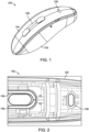
- FIG. 1 illustrates a representative ear-wearable electronic device in accordance with any of the embodiments disclosed herein.
- the ear-wearable electronic device 100 shown in FIG. 1 is representative of the behind-the-ear component of a Receiver-In-Canal (RIC) hearing device. It is understood that embodiments of the disclosure are not limited to a specific type of ear-wearable electronic device (e.g., a RIC hearing device), but may be implemented in any ear-wearable electronic device including those listed hereinabove.
- a RIC hearing device e.g., a RIC hearing device
- the ear-wearable electronic device 100 includes a housing 102 which is configured to rest behind an ear of the wearer.
- a RIC cable (not shown) is connected to the housing 102, at one end, and includes an earpiece, at the other end.
- the earpiece includes an acoustic transducer (e.g., a receiver) which produces audio output that is communicated through the wearer's ear canal to the eardrum.
- the housing 102 shown in FIG. 1 includes a housing wall 104, which can define a cover to the housing 102. Protruding through the housing wall 104 is a switch actuator 106, which can be configured as a rocker switch in some implementations.
- An elastomeric light pipe 108 is disposed in the housing wall 104 and optically coupled to a light source (e.g., an LED) positioned within the housing 102.
- a light source e.g., an LED
- the elastomeric light pipe 108 is spaced apart from the switch actuator 106 in an anterior direction.
- FIGS. 1 and 2 it is understood that more than one elastomeric light pipe 108 can be incorporated in the housing 102.
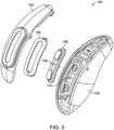
- FIG. 3 illustrates another configuration of the ear-wearable electronic device 100 in accordance with any of the embodiments disclosed herein.
- FIG. 3 is an exploded view of the ear-wearable electronic device 100 which shows various components of the device 100.
- the elastomeric light pipe 108 is positioned within the switch area of the housing 102.
- the elastomeric light pipe 108 can be disposed within a midsection of the switch actuator 106.
- the elastomeric light pipe 108 is positioned above an LED 110 disposed within the housing 102.
- a gasket member 109 is disposed between the switch actuator 106 and the housing wall 104 which defines a cover of the housing 102.
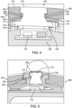
- FIGS. 4 and 5 illustrate a portion of a representative ear-wearable electronic device 100 in accordance with any of the embodiments disclosed herein.
- FIG. 4 is a lateral cross-sectional view of the housing 102.
- FIG. 5 is a longitudinal cross-sectional view of the housing 102.
- FIGS. 4 and 5 show the elastomeric light pipe 108 disposed in the housing wall 104 of the ear-wearable electronic device 100.
- the housing wall 104 can be a cover of the housing 102.
- the portion of the housing wall 104 shown in FIGS. 4 and 5 includes an outer surface 112, an inner surface 114, and an aperture 116 extending between the outer surface 112 and the inner surface 114.
- the elastomeric light pipe 108 is disposed within the aperture 116 and arranged to receive light from the light emitting device 110 (e.g., an LED).
- the light emitting device 110 e.g., an LED
- the elastomeric light pipe 108 shown in FIGS. 4 and 5 includes an outer section 115 which is exposed to an environment external of the housing 102.
- the elastomeric light pipe 108 also includes a flange 124 which abuts the inner surface 114 of the housing wall 104. In some configurations, the flange 124 forms a compression axial seal with the inner surface 114 of the housing wall 104.
- the elastomeric light pipe 108 further includes an intermediate section 117 which extends from the outer section 115 to the flange 124.
- the intermediate section 117 and the section of the housing wall 104 comprising the aperture 116 are configured to define a convoluted path (e.g., a tortuous path) for impeding passage of fluid between the outer and inner surfaces 112, 114 of the housing wall 104.
- a convoluted path e.g., a tortuous path
- the convoluted path extends along at least 50% of the aperture 116 in the housing wall 104. In other implementations, the convoluted path extends along at least 60% of the aperture 116 in the housing wall 104. In further implementations, the convoluted path extends along at least 70% of the aperture 116 in the housing wall 104. In other implementations, the convoluted path extends along at least 80% of the aperture 116 in the housing wall 104.
- the intermediate section 117 of the elastomeric light pipe 108 includes a first retention feature 120 comprising one or more recessed regions of the elastomeric light pipe 108.
- the first retention feature 120 can define a snap-fit feature of the elastomeric light pipe 108.
- the section of the housing wall 104 comprising the aperture 116 includes a second retention feature 122 configured to receive the first retention feature 120.
- the second retention feature 122 includes one or more protruding regions of the section of the housing wall 104 comprising the aperture 116.
- a snap-fit joint can be defined between the first retention feature 120 of the elastomeric light pipe 108 and the second retention feature 122 of the housing wall 104.
- one or more lap joints are formed between the section of the housing wall 104 comprising the aperture 116 and the intermediate section 117 of the elastomeric light pipe 108.
- the one or more lap joints can comprise two-surface or three-surface lap joints, for example.
- the LED 110 is mounted on an internal framework or spine 126 that is contained within the housing 102 and upon which may be mounted various internal components of the ear-wearable electronic device 100.
- sufficient space is provided between the spine 126 and the housing wall 104 to accommodate the LED 110 (e.g., as in the configuration shown in FIG. 3 ).
- the spacing between the spine 126 and the housing wall 104 can vary along the longitudinal axis of the housing wall 104.
- the LED 110 is mounted to a top surface of the spine 126 that faces the housing wall 104.
- the elastomeric light pipe 108 is positioned directly over the LED 110. At this location, the LED 110 can transmit light directly to the elastomeric light pipe 108.
- FIGS. 6 and 7 illustrate a portion of a representative ear-wearable electronic device 100 in accordance with any of the embodiments disclosed herein.
- FIG. 6 is a partial longitudinal cross-sectional view of the housing 102.
- FIG. 7 is an expanded view of FIG. 6 showing features of the elastomeric light pipe 108.
- the housing wall 104 of housing 102 includes an outer surface 112, an inner surface 114, and an aperture 116 extending between the outer and inner surfaces 112, 114.
- a light emitting device 110 e.g., an LED
- the elastomeric light pipe 108 is disposed within the aperture 116 and arranged to receive light from the LED 110.
- An interface 118 between a section of the housing wall 104 comprising the aperture 116 and the elastomeric light pipe 108 defines a convoluted path for impeding passage of fluid between the outer and inner surfaces 112, 114 of the housing wall 104.
- the LED 110 is disposed in the housing 102 below the spine 126.
- a cutout 128 (e.g., a void or via) is provided in the spine 126.
- a first end 127 of the cutout 128 is positioned above the LED 110.
- a second end 129 of the cutout 128 is positioned below the elastomeric light pipe 108.
- the cutout 128 is provided to facilitate transmission of light from the LED 110, through the spine 126, and to the elastomeric light pipe 108.
- FIGS. 4-6 are directed to a housing 102 of an ear-wearable electronic device 100 which incorporates a discrete elastomeric light pipe 108.
- the elastomeric light pipe 108 can be incorporated as an integral component of a gasket member.
- the gasket member 130 can be a full seam gasket member disposed between the housing 102 and the housing wall 104 (e.g., a cover of the housing 102).
- the gasket member 130 shown in FIG. 8 includes a first side 133 and an opposing second side 135.
- a support beam 131 is attached to, and extends between, the first and second sides 133, 135 of the gasket member 130.
- the support beam 131 includes an integral elastomeric light pipe 108.
- the integral elastomeric light pipe 108 can have a configuration similar or equivalent to that of the elastomeric light pipe 108 illustrated in FIGS. 4-7 .
- the elastomeric light pipe 108 can be an integral component of the gasket member 109 illustrated in FIG. 3 .
- the gasket member 109 can incorporate a support beam which includes an integral elastomeric light pipe 108 in a manner similar to that shown in FIG. 8 .
- the elastomeric light pipe 108 disclosed herein can comprise a substantially transparent elastomeric material, which can be a thermoplastic or thermoset elastomeric material.
- Suitable thermoplastic elastomers include TPU (thermoplastic polyurethanes) and TPV (thermoplastic vulcanizates, such as EPDM - ethylene propylene diene monomer).
- a suitable thermoset elastomer is silicone.
- the elastomeric light pipe 108 can comprise a translucent elastomeric material.
- FIG. 9 illustrates an installation tool 132 configured to facilitate installation of an elastomeric light pipe 108 in an aperture of a switch actuator 106.
- the installation tool 132 includes a handle 136 which can be grasped and manipulated by a technician.
- a pair of prongs 134 are connected to, and support, the elastomeric light pipe 108 at a distal and 137 of the handle 136.
- the technician forces the elastomeric light pipe 108 into the aperture of the switch actuator 106.
- the technician After installing the elastomeric light pipe 108 in the aperture of the switch actuator 106, the technician removes the installation tool 132 from the switch actuator 106, causing the elastomeric light pipe 108 to detach from the prongs 134 and leaving the elastomeric light pipe 108 in the aperture of the switch actuator 106.
- FIGS. 10A-10B are cross-sectional views of an elastomeric light pipe 108 with representative dimensions in accordance with any of the embodiments disclosed herein.
- the representative dimensions shown in FIGS. 10A-10B are given in inches. Representative dimensions are provided for the major structural features of the elastomeric light pipe 108, including a cap 111, an intermediate section 117, and a flange 124. It is understood that the representative dimensions shown in FIGS. 10A-10B are provided for illustration only, and that the elastomeric light pipe 108 can have dimensions that differ from those shown in FIGS. 10A-10B .
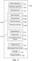
- FIG. 11 is a block diagram of a representative ear-wearable electronic device 1102 which incorporates a light emitting device 1101 and an elastomeric light pipe 1103 in accordance with any of the embodiments disclosed herein.
- the device 1102 is representative of a wide variety of electronic devices configured to be deployed in, on or about an ear of a wearer, including any of the devices discussed hereinabove.
- the device 1102 can include one or more RF radios/antennae 1107 (e.g., compliant with a Bluetooth ® or IEEE 802.11 protocol).
- the RF radios/antennae 1107 can be configured to effect communications with an external electronic device, communication system, and/or the cloud.
- the device 1102 includes a controller 1120, a rechargeable power source 1144, charging circuitry 1145, and charge contacts 1146.
- the device 1102 can include one or more sensors 1105.
- the device 1102 can include a motion sensor 1105a, one or more optical physiologic and non-physiologic sensors 1105b, one or more physiologic electrode-based sensors 1105c, and/or one or more temperature sensors 1105d.
- the device 1102 includes an audio processing facility 1170.
- the audio processing facility 1170 includes audio signal processing circuitry 1176 coupled to an acoustic transducer 1172 (e.g., speaker, receiver, bone conduction device) and to one or more microphones 1174.
- an acoustic transducer 1172 e.g., speaker, receiver, bone conduction device
- the device 1102 can be implemented as a hearing assistance device that can aid a person with impaired hearing.
- the device 1102 can be implemented as a monaural hearing aid or a pair of devices 1102 can be implemented as a binaural hearing aid system.
- the monaural device 1102 or a pair of devices 1102 can be configured to effect bi-directional communication (e.g., wireless communication) of data with an external source, such as a remote server via the Internet or other communication infrastructure.
- the device or devices 1102 can be configured to receive streaming audio (e.g., digital audio data or files) from an electronic or digital source.
- Representative electronic/digital sources include an assistive listening system, a streaming device (e.g., a TV streamer or audio streamer), a remote microphone, a radio, a smartphone, a laptop or other electronic device that serves as a source of digital audio data, control and/or settings data or commands, and/or other types of data files.
- a streaming device e.g., a TV streamer or audio streamer
- a remote microphone e.g., a radio, a smartphone, a laptop or other electronic device that serves as a source of digital audio data, control and/or settings data or commands, and/or other types of data files.
- the controller 1120 can include one or more processors or other logic devices.
- the controller 1120 can be representative of any combination of one or more logic devices (e.g., multi-core processor, digital signal processor (DSP), microprocessor, programmable controller, general-purpose processor, special-purpose processor, hardware controller, software controller, a combined hardware and software device) and/or other digital logic circuitry (e.g., ASICs, FPGAs), and software/firmware.
- the controller 1120 can incorporate or be coupled to various analog components (e.g., analog front-end), ADC and DAC components, and Filters (e.g., FIR filter, Kalman filter).
- the controller 1120 can incorporate or be coupled to memory.
- the memory can include one or more types of memory, including ROM, RAM, SDRAM, NVRAM, EEPROM, and FLASH, for example.
- Coupled or “connected” refer to elements being attached to each other either directly (in direct contact with each other) or indirectly (having one or more elements between and attaching the two elements). Either term may be modified by "operatively” and “operably,” which may be used interchangeably, to describe that the coupling or connection is configured to allow the components to interact to carry out at least some functionality.
- phrases "at least one of,” “comprises at least one of,” and “one or more of” followed by a list refers to any one of the items in the list and any combination of two or more items in the list.
Landscapes
- Engineering & Computer Science (AREA)
- Physics & Mathematics (AREA)
- Acoustics & Sound (AREA)
- Signal Processing (AREA)
- Health & Medical Sciences (AREA)
- General Health & Medical Sciences (AREA)
- Neurosurgery (AREA)
- Otolaryngology (AREA)
- Manufacturing & Machinery (AREA)
- Arrangement Of Elements, Cooling, Sealing, Or The Like Of Lighting Devices (AREA)
- Eyeglasses (AREA)
Abstract
An ear-wearable electronic device comprises a housing having a housing wall. The housing wall comprises an outer surface, an inner surface, and an aperture extending between the outer and inner surfaces. A light emitting device is disposed in the housing. An elastomeric light pipe is disposed within the aperture and arranged to receive light from the light emitting device. An interface between a section of the housing wall comprising the aperture and the elastomeric light pipe defines a convoluted path for impeding passage of fluid between the outer and inner surfaces of the housing wall.
Description
- This application claims the benefit of
63/545,306, filed October 23, 2023 - This application relates generally to ear-level electronic devices and systems, including hearing devices, personal amplification devices, hearing aids, bone conduction hearing devices, medical and consumer hearables, in-ear electronic appliances, electronic ear plugs, physiologic monitoring devices, biometric devices, and other ear-wearable electronic devices.
- Some embodiments are directed to an ear-wearable electronic device comprising a housing having a housing wall. The housing wall comprises an outer surface, an inner surface, and an aperture extending between the outer and inner surfaces. A light emitting device is disposed in the housing. An elastomeric light pipe is disposed within the aperture of the housing wall and arranged to receive light from the light emitting device. An interface between a section of the housing wall comprising the aperture and the elastomeric light pipe defines a convoluted path for impeding passage of fluid between the outer and inner surfaces of the housing wall.
- Some embodiments are directed to an ear-wearable electronic device comprising a housing having a housing wall. The housing wall comprises an outer surface, an inner surface, and an aperture extending between the outer and inner surfaces. A light emitting device is disposed in the housing. An elastomeric light pipe is disposed within the aperture of the housing wall and configured to receive light from the light emitting device. The elastomeric light pipe comprises an outer section exposed to an environment external of the housing, a flange in abutment with the inner surface, and an intermediate section extending from the outer section to the flange. The intermediate section and a section of the housing wall comprising the aperture are configured to define a convoluted path for impeding passage of fluid between the outer and inner surfaces of the housing wall.
- The above summary is not intended to describe each disclosed embodiment or every implementation of the present disclosure. The figures and the detailed description below more particularly exemplify illustrative embodiments.
- Throughout the specification reference is made to the appended drawings wherein:
-
FIG. 1 illustrates a representative ear-wearable electronic device which incorporates a light emitting device optically coupled to an elastomeric light pipe in accordance with any of the embodiments disclosed herein. -
FIG. 2 is an enlarged view of a portion of the ear-wearable electronic device shown inFIG. 1 . -
FIG. 3 illustrates a representative ear-wearable electronic device which incorporates a light emitting device optically coupled to an elastomeric light pipe in accordance with any of the embodiments disclosed herein. -
FIG. 4 illustrates details of an elastomeric light pipe optically coupled to a light emitting device in accordance with any of the embodiments disclosed herein. -
FIG. 5 illustrates details of an elastomeric light pipe optically coupled to a light emitting device in accordance with any of the embodiments disclosed herein. -
FIG. 6 illustrates details of an elastomeric light pipe optically coupled to a light emitting device in accordance with any of the embodiments disclosed herein. -
FIG. 7 is an enlarged view of a portion ofFIG. 6 showing details of an elastomeric light pipe in accordance with any of the embodiments disclosed herein. -
FIG. 8 illustrates a gasket member which incorporates an integral elastomeric light pipe in accordance with any of the embodiments disclosed herein. -
FIG. 9 illustrates an installation tool for installing an elastomeric light pipe in an aperture of a housing wall of an ear-wearable electronic device in accordance with any of the embodiments disclosed herein. -
FIGS. 10A-10B are views of an elastomeric light pipe with representative dimensions in accordance with any of the embodiments disclosed herein. -
FIG. 11 is a block diagram of a representative ear-wearable electronic device which can incorporate an elastomeric light pipe and light emitting device in accordance with any of the embodiments disclosed herein. - The figures are not necessarily to scale. Like numbers used in the figures refer to like components. However, it will be understood that the use of a number to refer to a component in a given figure is not intended to limit the component in another figure labeled with the same number.
- Embodiments disclosed herein are directed to any ear-wearable or ear-level electronic device without departing from the scope of this disclosure. The devices depicted in the figures are intended to demonstrate the subject matter, but not in a limited, exhaustive, or exclusive sense. Ear-wearable electronic devices, such as hearables (e.g., ear monitors, earbuds, electronic earplugs), hearing aids, hearing instruments, and hearing assistance devices, typically include an enclosure, such as a housing or shell, within which internal components are disposed. Typical components of an ear-wearable electronic device can include a processor (e.g., a digital signal processor or DSP), memory circuitry, power management and charging circuitry, one or more communication devices (e.g., one or more radios, a near-field magnetic induction (NFMI) device), one or more antennas, one or more microphones, buttons and/or switches, and a receiver/speaker, for example. Ear-wearable electronic devices can incorporate a long-range communication device, such as a Bluetooth® transceiver or other type of radio frequency (RF) transceiver. In some implementations, a communication facility (e.g., a radio or NFMI device) of an ear-wearable electronic device can be configured to facilitate communication between a left hearing device and a right hearing device of a hearing device system.
- Some embodiments are directed to hearing devices that can aid a person with impaired hearing. Hearing devices include, but are not limited to, behind-the-ear (BTE), in-the-ear (ITE), in-the-canal (ITC), invisible-in-canal (IIC), receiver-in-canal (RIC), receiver-in-the-ear (RITE) or completely-in-the-canal (CIC) type hearing devices or some combination of the above. Throughout this disclosure, reference is made to an ear-wearable electronic device, which is understood to refer to a system comprising a single left ear device, a single right ear device, or a combination of a left ear device and a right ear device.
- A conventional ear-level electronic device, such as a hearing device, may communicate different states of the device to the wearer through audio output. Audio output alone provides insufficient information to the wearer or a caregiver (e.g., a hearing professional) in a variety of circumstances. When fitting a new hearing device to a wearer, for example, audio output from the hearing device cannot be perceived by the caregiver. As such, the caregiver may be unaware of the device status (e.g., programming status, Bluetooth connectivity status) while fitting the new hearing device to the wearer.
- In some cases, different states of a conventional ear-level electronic device may be communicated to the wearer via an app executed by a mobile electronic device (e.g., a smartphone). Such communication with the ear-level electronic device, however, requires the wearer to have access to the mobile electronic device, which may not be possible in some instances. Also, the wearer must have sufficient training to use the app executed by the mobile electronic device, which may be challenging for less sophisticated users.
- Embodiments of the disclosure are directed to an ear-wearable electronic device which incorporates a light emitting device optically coupled to an elastomeric light pipe with ingress resistance features. The light emitting device and elastomeric light pipe are arranged to provide a visual indication as to the status of the ear-wearable electronic device. For example, visual indications of device programming status, Bluetooth pairing status, state of charge status, and device malfunctions can be communicated to the wearer via the light emitting device and elastomeric light pipe arrangement.
- Inclusion of a light emitting device in the ear-wearable electronic device requires an opening in the device housing in order for light to be transmitted to the external environment. Such an opening, however, provides a potential ingress path for fluids (e.g., water) to pass into the interior of the device housing. An elastomeric light pipe of the present disclosure incorporates ingress resistance features which mitigate the ingress of fluid passing through an opening in the device housing. The elastomeric light pipe communicates light produced by the light emitting device to the external environment, providing visual indications to the wearer as to the status of the device.
- Embodiments of the disclosure are defined in the claims. However, below there is provided a non-exhaustive listing of non-limiting examples. Any one or more of the features of these examples may be combined with any one or more features of another example, embodiment, or aspect described herein.
- Example Ex1. An ear-wearable electronic device comprises a housing having a housing wall comprising an outer surface, an inner surface, and an aperture extending between the outer and inner surfaces. A light emitting device is disposed in the housing, and an elastomeric light pipe is disposed within the aperture and arranged to receive light from the light emitting device. An interface between a section of the housing wall comprising the aperture and the elastomeric light pipe defines a convoluted path for impeding passage of fluid between the outer and inner surfaces of the housing wall.
- Example Ex2. The device according to Ex1, wherein the elastomeric light pipe comprises a first retention feature and the section of the housing wall comprising the aperture comprises a second retention feature configured to receive the first retention feature.
- Example Ex3. The device according to Ex2, wherein the first retention feature of the elastomeric light pipe comprises a snap-fit feature.
- Example Ex4. The device according to Ex2 or Ex3, wherein the first retention feature comprises one or more recessed regions of the elastomeric light pipe, and the second retention feature comprises one or more protruding regions of the section of the housing wall comprising the aperture.
- Example Ex5. The device according to one or more of Ex1 to Ex4, wherein the elastomeric light pipe comprises a solid elastomeric member.
- Example Ex6. The device according to one or more of Ex1 to Ex5, wherein the elastomeric light pipe comprises a thermoplastic elastomeric material or a thermoset elastomeric material.
- Example Ex7. The device according to one or more of Ex1 to Ex6, comprising a plurality of lap joints formed between the housing wall section comprising the aperture and the elastomeric light pipe.
- Example Ex8. The device according to Ex7, wherein the plurality of lap joints comprises two-surface or three-surface lap joints.
- Example Ex9. The device according to one or more of Ex1 to Ex8, wherein the elastomeric light pipe comprises a flange configured to form a compression axial seal with the inner surface of the housing wall.
- Example Ex10. The device according to one or more of Ex1 to Ex9, comprising a spine disposed within the housing and configured to support components of the ear-wearable electronic device, wherein the light emitting device is disposed on a top surface of the spine that faces the inner surface of the housing wall, and the elastomeric light pipe is positioned over the light emitting device.
- Example Ex11. The device according to one or more of Ex1 to Ex9, comprising a spine disposed within the housing and configured to support components of the ear-wearable electronic device, wherein the light emitting device is disposed in the housing proximate a cutout through the spine, and the elastomeric light pipe is positioned over the cutout.
- Example Ex12. The device according to one or more of Ex1 to Ex11, wherein the light emitting device and the elastomeric light pipe are situated within or proximate a switch area of the housing.
- Example Ex13. The device according to one or more of Ex1 to Ex12, comprising an elastomeric gasket member disposed between first and second sections of the housing, wherein the elastomeric light pipe is integral to the elastomeric gasket member.
- Example Ex14. An ear-wearable electronic device comprises a housing having a housing wall comprising an outer surface, an inner surface, and an aperture extending between the outer and inner surfaces. A light emitting device is disposed in the housing. An elastomeric light pipe is disposed within the aperture and configured to receive light from the light emitting device. The elastomeric light pipe comprises an outer section exposed to an environment external of the housing, a flange in abutment with the inner surface, and an intermediate section extending from the outer section to the flange, the intermediate section and a section of the housing wall comprising the aperture configured to define a convoluted path for impeding passage of fluid between the outer and inner surfaces of the housing wall.
- Example Ex15. The device according to Ex 14, wherein the flange is configured to form a compression axial seal with the inner surface of the housing wall.
- Example Ex16. The device according to Ex14 or Ex15, wherein the intermediate section of the elastomeric light pipe comprises a first retention feature and the section of the housing wall comprising the aperture comprises a second retention feature configured to receive the first retention feature.
- Example Ex17. The device according to Ex16, wherein the first retention feature comprises a snap-fit feature.
- Example Ex18. The device according to Ex16 or Ex17, wherein the first retention feature comprises one or more recessed regions of the elastomeric light pipe, and the second retention feature comprises one or more protruding regions of the section of the housing wall comprising the aperture.
- Example Ex19. The device according to one or more of Ex14 to Ex18, wherein the elastomeric light pipe comprises a solid elastomeric member.
- Example Ex20. The device according to one or more of Ex14 to Ex19, wherein the elastomeric light pipe comprises a thermoplastic elastomeric material or a thermoset elastomeric material.
- Example Ex21. The device according to one or more of Ex14 to Ex20, comprising a plurality of lap joints formed between the housing wall section comprising the aperture and the intermediate section of the elastomeric light pipe.
- Example Ex22. The device according to Ex21, wherein the plurality of lap joints comprises two-surface or three-surface lap joints.
- Example Ex23. The device according to one or more of Ex14 to Ex22, comprising a spine disposed within the housing and configured to support components of the ear-wearable electronic device, wherein the light emitting device is disposed on a top surface of the spine that faces the inner surface of the housing wall, and the elastomeric light pipe is positioned over the light emitting device.
- Example Ex24. The device according to one or more of Ex 14 to Ex22, comprising a spine disposed within the housing and configured to support components of the ear-wearable electronic device, wherein the light emitting device is disposed in the housing proximate a cutout through the spine, and the elastomeric light pipe is positioned over the cutout.
- Example Ex25. The device according to one or more of Ex14 to Ex24, wherein the light emitting device and the elastomeric light pipe are situated within or proximate a switch area of the housing.
- Example Ex26. The device according to one or more of Ex14 to Ex25, comprising an elastomeric gasket member disposed between first and second sections of the housing, wherein the elastomeric light pipe is integral to the elastomeric gasket member.
-
FIG. 1 illustrates a representative ear-wearable electronic device in accordance with any of the embodiments disclosed herein. The ear-wearableelectronic device 100 shown inFIG. 1 is representative of the behind-the-ear component of a Receiver-In-Canal (RIC) hearing device. It is understood that embodiments of the disclosure are not limited to a specific type of ear-wearable electronic device (e.g., a RIC hearing device), but may be implemented in any ear-wearable electronic device including those listed hereinabove. - The ear-wearable
electronic device 100 includes ahousing 102 which is configured to rest behind an ear of the wearer. In this configuration, a RIC cable (not shown) is connected to thehousing 102, at one end, and includes an earpiece, at the other end. The earpiece includes an acoustic transducer (e.g., a receiver) which produces audio output that is communicated through the wearer's ear canal to the eardrum. - The
housing 102 shown inFIG. 1 includes ahousing wall 104, which can define a cover to thehousing 102. Protruding through thehousing wall 104 is aswitch actuator 106, which can be configured as a rocker switch in some implementations. Anelastomeric light pipe 108 is disposed in thehousing wall 104 and optically coupled to a light source (e.g., an LED) positioned within thehousing 102. In the configuration shown inFIG. 1 and FIG. 2 (an enlarged view of thehousing 102 shown inFIG. 1 with thehousing wall 104 hidden), theelastomeric light pipe 108 is spaced apart from theswitch actuator 106 in an anterior direction. Although a singleelastomeric light pipe 108 is shown inFIGS. 1 and 2 , it is understood that more than oneelastomeric light pipe 108 can be incorporated in thehousing 102. -
FIG. 3 illustrates another configuration of the ear-wearableelectronic device 100 in accordance with any of the embodiments disclosed herein.FIG. 3 is an exploded view of the ear-wearableelectronic device 100 which shows various components of thedevice 100. In the configuration shown inFIG. 3 , theelastomeric light pipe 108 is positioned within the switch area of thehousing 102. Theelastomeric light pipe 108 can be disposed within a midsection of theswitch actuator 106. As can be seen inFIG. 3 , theelastomeric light pipe 108 is positioned above anLED 110 disposed within thehousing 102. Agasket member 109 is disposed between theswitch actuator 106 and thehousing wall 104 which defines a cover of thehousing 102. -
FIGS. 4 and 5 illustrate a portion of a representative ear-wearableelectronic device 100 in accordance with any of the embodiments disclosed herein.FIG. 4 is a lateral cross-sectional view of thehousing 102.FIG. 5 is a longitudinal cross-sectional view of thehousing 102.FIGS. 4 and 5 show theelastomeric light pipe 108 disposed in thehousing wall 104 of the ear-wearableelectronic device 100. Thehousing wall 104 can be a cover of thehousing 102. The portion of thehousing wall 104 shown inFIGS. 4 and 5 includes anouter surface 112, aninner surface 114, and anaperture 116 extending between theouter surface 112 and theinner surface 114. Theelastomeric light pipe 108 is disposed within theaperture 116 and arranged to receive light from the light emitting device 110 (e.g., an LED). - The
elastomeric light pipe 108 shown inFIGS. 4 and 5 includes anouter section 115 which is exposed to an environment external of thehousing 102. Theelastomeric light pipe 108 also includes aflange 124 which abuts theinner surface 114 of thehousing wall 104. In some configurations, theflange 124 forms a compression axial seal with theinner surface 114 of thehousing wall 104. Theelastomeric light pipe 108 further includes anintermediate section 117 which extends from theouter section 115 to theflange 124. Theintermediate section 117 and the section of thehousing wall 104 comprising theaperture 116 are configured to define a convoluted path (e.g., a tortuous path) for impeding passage of fluid between the outer andinner surfaces housing wall 104. - In some implementations, the convoluted path extends along at least 50% of the
aperture 116 in thehousing wall 104. In other implementations, the convoluted path extends along at least 60% of theaperture 116 in thehousing wall 104. In further implementations, the convoluted path extends along at least 70% of theaperture 116 in thehousing wall 104. In other implementations, the convoluted path extends along at least 80% of theaperture 116 in thehousing wall 104. - The
intermediate section 117 of theelastomeric light pipe 108 includes afirst retention feature 120 comprising one or more recessed regions of theelastomeric light pipe 108. Thefirst retention feature 120 can define a snap-fit feature of theelastomeric light pipe 108. The section of thehousing wall 104 comprising theaperture 116 includes asecond retention feature 122 configured to receive thefirst retention feature 120. Thesecond retention feature 122 includes one or more protruding regions of the section of thehousing wall 104 comprising theaperture 116. A snap-fit joint can be defined between thefirst retention feature 120 of theelastomeric light pipe 108 and thesecond retention feature 122 of thehousing wall 104. In some configurations, one or more lap joints are formed between the section of thehousing wall 104 comprising theaperture 116 and theintermediate section 117 of theelastomeric light pipe 108. The one or more lap joints can comprise two-surface or three-surface lap joints, for example. - In the configuration shown in
FIGS. 4 and 5 , theLED 110 is mounted on an internal framework orspine 126 that is contained within thehousing 102 and upon which may be mounted various internal components of the ear-wearableelectronic device 100. In the configuration shown inFIGS. 4 and 5 , sufficient space is provided between thespine 126 and thehousing wall 104 to accommodate the LED 110 (e.g., as in the configuration shown inFIG. 3 ). It is noted that the spacing between thespine 126 and thehousing wall 104 can vary along the longitudinal axis of thehousing wall 104. As shown, theLED 110 is mounted to a top surface of thespine 126 that faces thehousing wall 104. Theelastomeric light pipe 108 is positioned directly over theLED 110. At this location, theLED 110 can transmit light directly to theelastomeric light pipe 108. -
FIGS. 6 and 7 illustrate a portion of a representative ear-wearableelectronic device 100 in accordance with any of the embodiments disclosed herein.FIG. 6 is a partial longitudinal cross-sectional view of thehousing 102.FIG. 7 is an expanded view ofFIG. 6 showing features of theelastomeric light pipe 108. Thehousing wall 104 ofhousing 102 includes anouter surface 112, aninner surface 114, and anaperture 116 extending between the outer andinner surfaces housing 102. Theelastomeric light pipe 108 is disposed within theaperture 116 and arranged to receive light from theLED 110. Aninterface 118 between a section of thehousing wall 104 comprising theaperture 116 and theelastomeric light pipe 108 defines a convoluted path for impeding passage of fluid between the outer andinner surfaces housing wall 104. - In some configurations, such as that shown in
FIGS. 6 and 7 , there is insufficient space provided between thespine 126 and thehousing wall 104 to accommodate the LED 110 (e.g., as in the configuration shown inFIG 1 ). As is shown inFIGS. 6 and 7 , theLED 110 is disposed in thehousing 102 below thespine 126. A cutout 128 (e.g., a void or via) is provided in thespine 126. Afirst end 127 of thecutout 128 is positioned above theLED 110. Asecond end 129 of thecutout 128 is positioned below theelastomeric light pipe 108. Thecutout 128 is provided to facilitate transmission of light from theLED 110, through thespine 126, and to theelastomeric light pipe 108. -
FIGS. 4-6 are directed to ahousing 102 of an ear-wearableelectronic device 100 which incorporates a discrete elastomericlight pipe 108. In some embodiments, theelastomeric light pipe 108 can be incorporated as an integral component of a gasket member. In some implementations, and as illustrated inFIG. 8 , thegasket member 130 can be a full seam gasket member disposed between thehousing 102 and the housing wall 104 (e.g., a cover of the housing 102). Thegasket member 130 shown inFIG. 8 includes afirst side 133 and an opposingsecond side 135. Asupport beam 131 is attached to, and extends between, the first andsecond sides gasket member 130. Thesupport beam 131 includes an integral elastomericlight pipe 108. The integral elastomericlight pipe 108 can have a configuration similar or equivalent to that of theelastomeric light pipe 108 illustrated inFIGS. 4-7 . - In other implementations, the
elastomeric light pipe 108 can be an integral component of thegasket member 109 illustrated inFIG. 3 . In such implementations, thegasket member 109 can incorporate a support beam which includes an integral elastomericlight pipe 108 in a manner similar to that shown inFIG. 8 . - The
elastomeric light pipe 108 disclosed herein can comprise a substantially transparent elastomeric material, which can be a thermoplastic or thermoset elastomeric material. Suitable thermoplastic elastomers include TPU (thermoplastic polyurethanes) and TPV (thermoplastic vulcanizates, such as EPDM - ethylene propylene diene monomer). A suitable thermoset elastomer is silicone. In some implementations, theelastomeric light pipe 108 can comprise a translucent elastomeric material. -
FIG. 9 illustrates aninstallation tool 132 configured to facilitate installation of anelastomeric light pipe 108 in an aperture of aswitch actuator 106. Theinstallation tool 132 includes ahandle 136 which can be grasped and manipulated by a technician. A pair ofprongs 134 are connected to, and support, theelastomeric light pipe 108 at a distal and 137 of thehandle 136. Using theinstallation tool 132, the technician forces theelastomeric light pipe 108 into the aperture of theswitch actuator 106. After installing theelastomeric light pipe 108 in the aperture of theswitch actuator 106, the technician removes theinstallation tool 132 from theswitch actuator 106, causing theelastomeric light pipe 108 to detach from theprongs 134 and leaving theelastomeric light pipe 108 in the aperture of theswitch actuator 106. -
FIGS. 10A-10B are cross-sectional views of anelastomeric light pipe 108 with representative dimensions in accordance with any of the embodiments disclosed herein. The representative dimensions shown inFIGS. 10A-10B are given in inches. Representative dimensions are provided for the major structural features of theelastomeric light pipe 108, including acap 111, anintermediate section 117, and aflange 124. It is understood that the representative dimensions shown inFIGS. 10A-10B are provided for illustration only, and that theelastomeric light pipe 108 can have dimensions that differ from those shown inFIGS. 10A-10B . -
FIG. 11 is a block diagram of a representative ear-wearableelectronic device 1102 which incorporates alight emitting device 1101 and anelastomeric light pipe 1103 in accordance with any of the embodiments disclosed herein. Thedevice 1102 is representative of a wide variety of electronic devices configured to be deployed in, on or about an ear of a wearer, including any of the devices discussed hereinabove. Thedevice 1102 can include one or more RF radios/antennae 1107 (e.g., compliant with a Bluetooth® or IEEE 802.11 protocol). The RF radios/antennae 1107 can be configured to effect communications with an external electronic device, communication system, and/or the cloud. Thedevice 1102 includes acontroller 1120, arechargeable power source 1144, chargingcircuitry 1145, andcharge contacts 1146. - The
device 1102 can include one ormore sensors 1105. For example, thedevice 1102 can include amotion sensor 1105a, one or more optical physiologic andnon-physiologic sensors 1105b, one or more physiologic electrode-basedsensors 1105c, and/or one ormore temperature sensors 1105d. - The
device 1102 includes anaudio processing facility 1170. Theaudio processing facility 1170 includes audiosignal processing circuitry 1176 coupled to an acoustic transducer 1172 (e.g., speaker, receiver, bone conduction device) and to one ormore microphones 1174. - According to some embodiments, the
device 1102 can be implemented as a hearing assistance device that can aid a person with impaired hearing. For example, thedevice 1102 can be implemented as a monaural hearing aid or a pair ofdevices 1102 can be implemented as a binaural hearing aid system. Themonaural device 1102 or a pair ofdevices 1102 can be configured to effect bi-directional communication (e.g., wireless communication) of data with an external source, such as a remote server via the Internet or other communication infrastructure. The device ordevices 1102 can be configured to receive streaming audio (e.g., digital audio data or files) from an electronic or digital source. Representative electronic/digital sources (e.g., accessory devices) include an assistive listening system, a streaming device (e.g., a TV streamer or audio streamer), a remote microphone, a radio, a smartphone, a laptop or other electronic device that serves as a source of digital audio data, control and/or settings data or commands, and/or other types of data files. - The
controller 1120 can include one or more processors or other logic devices. For example, thecontroller 1120 can be representative of any combination of one or more logic devices (e.g., multi-core processor, digital signal processor (DSP), microprocessor, programmable controller, general-purpose processor, special-purpose processor, hardware controller, software controller, a combined hardware and software device) and/or other digital logic circuitry (e.g., ASICs, FPGAs), and software/firmware. Thecontroller 1120 can incorporate or be coupled to various analog components (e.g., analog front-end), ADC and DAC components, and Filters (e.g., FIR filter, Kalman filter). Thecontroller 1120 can incorporate or be coupled to memory. The memory can include one or more types of memory, including ROM, RAM, SDRAM, NVRAM, EEPROM, and FLASH, for example. - Although reference is made herein to the accompanying set of drawings that form part of this disclosure, one of at least ordinary skill in the art will appreciate that various adaptations and modifications of the embodiments described herein are within, or do not depart from, the scope of this disclosure. For example, aspects of the embodiments described herein may be combined in a variety of ways with each other. Therefore, it is to be understood that, within the scope of the appended claims, the claimed subject matter may be practiced other than as explicitly described herein.
- Unless otherwise indicated, all numbers expressing feature sizes, amounts, and physical properties used in the specification and claims may be understood as being modified either by the term "exactly" or "about." Accordingly, unless indicated to the contrary, the numerical parameters set forth in the foregoing specification and attached claims are approximations that can vary depending upon the desired properties sought to be obtained by those skilled in the art utilizing the teachings disclosed herein or, for example, within typical ranges of experimental error.
- The recitation of numerical ranges by endpoints includes all numbers subsumed within that range (e.g., 1 to 5 includes 1, 1.5, 2, 2.75, 3, 3.80, 4, and 5) and any range within that range. Herein, the terms "up to" or "no greater than" a number (e.g., up to 50) includes the number (e.g., 50), and the term "no less than" a number (e.g., no less than 5) includes the number (e.g., 5).
- The terms "coupled" or "connected" refer to elements being attached to each other either directly (in direct contact with each other) or indirectly (having one or more elements between and attaching the two elements). Either term may be modified by "operatively" and "operably," which may be used interchangeably, to describe that the coupling or connection is configured to allow the components to interact to carry out at least some functionality.
- Terms related to orientation, such as "top," "bottom," "side," and "end," are used to describe relative positions of components and are not meant to limit the orientation of the embodiments contemplated. For example, an embodiment described as having a "top" and "bottom" also encompasses embodiments thereof rotated in various directions unless the content clearly dictates otherwise.
- Reference to "one embodiment," "an embodiment," "certain embodiments," or "some embodiments," etc., means that a particular feature, configuration, composition, or characteristic described in connection with the embodiment is included in at least one embodiment of the disclosure. Thus, the appearances of such phrases in various places throughout are not necessarily referring to the same embodiment of the disclosure. Furthermore, the particular features, configurations, compositions, or characteristics may be combined in any suitable manner in one or more embodiments.
- As used in this specification and the appended claims, the singular forms "a," "an," and "the" encompass embodiments having plural referents, unless the content clearly dictates otherwise. As used in this specification and the appended claims, the term "or" is generally employed in its sense including "and/or" unless the content clearly dictates otherwise.
- As used herein, "have," "having," "include," "including," "comprise," "comprising" or the like are used in their open-ended sense, and generally mean "including, but not limited to." The term "and/or" means one or all of the listed elements or a combination of at least two of the listed elements.
- The phrases "at least one of," "comprises at least one of," and "one or more of" followed by a list refers to any one of the items in the list and any combination of two or more items in the list.
Claims (15)
- An ear-wearable electronic device, comprising:a housing comprising a housing wall, the housing wall comprising an outer surface, an inner surface, and an aperture extending between the outer and inner surfaces;a light emitting device disposed in the housing; andan elastomeric light pipe disposed within the aperture and arranged to receive light from the light emitting device, an interface between a section of the housing wall comprising the aperture and the elastomeric light pipe defining a convoluted path for impeding passage of fluid between the outer and inner surfaces of the housing wall.
- The device according to claim 1, wherein the elastomeric light pipe comprises a first retention feature and the section of the housing wall comprising the aperture comprises a second retention feature configured to receive the first retention feature, preferably wherein the first retention feature of the elastomeric light pipe comprises a snap-fit feature.
- The device according to claim 2, wherein:the first retention feature comprises one or more recessed regions of the elastomeric light pipe; andthe second retention feature comprises one or more protruding regions of the section of the housing wall comprising the aperture.
- The device according to any of claims 1 to 3,wherein the elastomeric light pipe comprises a solid elastomeric member; and/orwherein the elastomeric light pipe comprises a thermoplastic elastomeric material or a thermoset elastomeric material.
- The device according to any of claims 1 to 4, comprising a plurality of lap joints formed between the housing wall section comprising the aperture and the elastomeric light pipe.
- The device according to any of claims 1 to 5, wherein the elastomeric light pipe comprises a flange configured to form a compression axial seal with the inner surface of the housing wall.
- The device according to any of claims 1 to 6, comprising a spine disposed within the housing and configured to support components of the ear-wearable electronic device, wherein:the light emitting device is disposed on a top surface of the spine that faces the inner surface of the housing wall; andthe elastomeric light pipe is positioned over the light emitting device; orwherein:the light emitting device is disposed in the housing proximate a cutout through the spine; andthe elastomeric light pipe is positioned over the cutout.
- The device according to any of claims 1 to 7, wherein the light emitting device and the elastomeric light pipe are situated within or proximate a switch area of the housing.
- The device according to any of claims 1 to 8, comprising an elastomeric gasket member disposed between first and second sections of the housing, wherein the elastomeric light pipe is integral to the elastomeric gasket member.
- An ear-wearable electronic device, comprising:a housing comprising a housing wall, the housing wall comprising an outer surface, an inner surface, and an aperture extending between the outer and inner surfaces;a light emitting device disposed in the housing; andan elastomeric light pipe disposed within the aperture and configured to receive light from the light emitting device, the elastomeric light pipe comprising:an outer section exposed to an environment external of the housing;a flange in abutment with the inner surface; andan intermediate section extending from the outer section to the flange, the intermediate section and a section of the housing wall comprising the aperture configured to define a convoluted path for impeding passage of fluid between the outer and inner surfaces of the housing wall.
- The device according to claim 10,wherein the flange is configured to form a compression axial seal with the inner surface of the housing wall; and/orwherein the light emitting device and the elastomeric light pipe are situated within or proximate a switch area of the housing; and/orwherein the intermediate section of the elastomeric light pipe comprises a first retention feature and the section of the housing wall comprising the aperture comprises a second retention feature configured to receive the first retention feature, preferably wherein the first retention feature comprises a snap-fit feature.
- The device according to any of claims 10 or 11, wherein:the first retention feature comprises one or more recessed regions of the elastomeric light pipe; andthe second retention feature comprises one or more protruding regions of the section of the housing wall comprising the aperture.
- The device according to any of claims 10 to 12,wherein the elastomeric light pipe comprises a solid elastomeric member and/or wherein the elastomeric light pipe comprises a thermoplastic elastomeric material or a thermoset elastomeric material; and/orwherein the device further comprises a plurality of lap joints formed between the housing wall section comprising the aperture and the intermediate section of the elastomeric light pipe.
- The device according to any of claims 10 to 13, comprising a spine disposed within the housing and configured to support components of the ear-wearable electronic device, wherein:the light emitting device is disposed on a top surface of the spine that faces the inner surface of the housing wall; andthe elastomeric light pipe is positioned over the light emitting device; orwherein:the light emitting device is disposed in the housing proximate a cutout through the spine; andthe elastomeric light pipe is positioned over the cutout.
- The device according to any of claims 10 to 14, comprising an elastomeric gasket member disposed between first and second sections of the housing, wherein the elastomeric light pipe is integral to the elastomeric gasket member.
Applications Claiming Priority (2)
| Application Number | Priority Date | Filing Date | Title |
|---|---|---|---|
| US202363545306P | 2023-10-23 | 2023-10-23 | |
| US18/906,751 US20250133356A1 (en) | 2023-10-23 | 2024-10-04 | Ear-wearable electronic device including elastomeric light pipe with ingress resistance features |
Publications (1)
| Publication Number | Publication Date |
|---|---|
| EP4546816A1 true EP4546816A1 (en) | 2025-04-30 |
Family
ID=93154565
Family Applications (1)
| Application Number | Title | Priority Date | Filing Date |
|---|---|---|---|
| EP24207136.3A Pending EP4546816A1 (en) | 2023-10-23 | 2024-10-17 | Ear-wearable electronic device including elastomeric light pipe with ingress resistance features |
Country Status (2)
| Country | Link |
|---|---|
| US (1) | US20250133356A1 (en) |
| EP (1) | EP4546816A1 (en) |
Citations (3)
| Publication number | Priority date | Publication date | Assignee | Title |
|---|---|---|---|---|
| US20090003014A1 (en) * | 2005-12-09 | 2009-01-01 | All Innovations Pty Ltd | Light Guides, Illuminated Articles and Devices |
| CN210272132U (en) * | 2019-06-10 | 2020-04-07 | 安克创新科技股份有限公司 | Light guide waterproof key device and earphone |
| CN211240055U (en) * | 2020-01-15 | 2020-08-11 | 深圳市睿耳电子有限公司 | Earphone light guide structure and earphone |
-
2024
- 2024-10-04 US US18/906,751 patent/US20250133356A1/en active Pending
- 2024-10-17 EP EP24207136.3A patent/EP4546816A1/en active Pending
Patent Citations (3)
| Publication number | Priority date | Publication date | Assignee | Title |
|---|---|---|---|---|
| US20090003014A1 (en) * | 2005-12-09 | 2009-01-01 | All Innovations Pty Ltd | Light Guides, Illuminated Articles and Devices |
| CN210272132U (en) * | 2019-06-10 | 2020-04-07 | 安克创新科技股份有限公司 | Light guide waterproof key device and earphone |
| CN211240055U (en) * | 2020-01-15 | 2020-08-11 | 深圳市睿耳电子有限公司 | Earphone light guide structure and earphone |
Also Published As
| Publication number | Publication date |
|---|---|
| US20250133356A1 (en) | 2025-04-24 |
Similar Documents
| Publication | Publication Date | Title |
|---|---|---|
| US20240305933A1 (en) | Ear-wearable hearing device | |
| JP5150798B1 (en) | Hearing aid earplugs and hearing aids | |
| US9467787B2 (en) | Hearing aid with a replaceable insertion cap | |
| EP2238772B1 (en) | Modular hearing instrument | |
| US20040165742A1 (en) | Canal hearing device with tubular insert | |
| EP1681904B1 (en) | Hearing instrument | |
| EP4586648A1 (en) | Flanged earbud and ear-wearable electronic device including same | |
| EP2635046A1 (en) | A method of fitting a binaural hearing aid system | |
| US12513475B2 (en) | Cable connector for hearing device | |
| EP3334179B1 (en) | Hearing aid with an extended dome | |
| US20250267392A1 (en) | Ear-wearable electronic device including acoustic filter | |
| EP2503797A2 (en) | Compact programming block connector for hearing assistance devices | |
| EP1535489A1 (en) | Canal hearing device with tubular insert | |
| EP4007304B1 (en) | Earpiece for a hearing device, dome and earpiece part | |
| EP3383068B1 (en) | Automated assessment and adjustment of tinnitus-masker impact on speech intelligibility during fitting | |
| US20250133356A1 (en) | Ear-wearable electronic device including elastomeric light pipe with ingress resistance features | |
| US20130077808A1 (en) | Ite hearing instrument with programming connector | |
| US20250280250A1 (en) | Hearing device and earpiece with active vent | |
| JP2020184746A (en) | Hearing device having vent | |
| US20220109938A1 (en) | Ear-worn electronic device incorporating microphone fault reduction system and method | |
| EP4040804B1 (en) | Binaural hearing device with noise reduction in voice during a call | |
| US20260012738A1 (en) | Ear-wearable electronic device including baffle | |
| EP4668782A1 (en) | Ear-wearable electronic device | |
| EP4572338A1 (en) | Contralateral-hearing interference reduction | |
| EP4254986A1 (en) | An earpiece for a hearing device and a method of detachable assembly of an earpiece of a hearing device |
Legal Events
| Date | Code | Title | Description |
|---|---|---|---|
| PUAI | Public reference made under article 153(3) epc to a published international application that has entered the european phase |
Free format text: ORIGINAL CODE: 0009012 |
|
| STAA | Information on the status of an ep patent application or granted ep patent |
Free format text: STATUS: THE APPLICATION HAS BEEN PUBLISHED |
|
| AK | Designated contracting states |
Kind code of ref document: A1 Designated state(s): AL AT BE BG CH CY CZ DE DK EE ES FI FR GB GR HR HU IE IS IT LI LT LU LV MC ME MK MT NL NO PL PT RO RS SE SI SK SM TR |
|
| STAA | Information on the status of an ep patent application or granted ep patent |
Free format text: STATUS: REQUEST FOR EXAMINATION WAS MADE |
|
| 17P | Request for examination filed |
Effective date: 20251030 |
|
| STAA | Information on the status of an ep patent application or granted ep patent |
Free format text: STATUS: EXAMINATION IS IN PROGRESS |