EP4546774A1 - Inter-coding transform for autoencoders - Google Patents
Inter-coding transform for autoencoders Download PDFInfo
- Publication number
- EP4546774A1 EP4546774A1 EP24208617.1A EP24208617A EP4546774A1 EP 4546774 A1 EP4546774 A1 EP 4546774A1 EP 24208617 A EP24208617 A EP 24208617A EP 4546774 A1 EP4546774 A1 EP 4546774A1
- Authority
- EP
- European Patent Office
- Prior art keywords
- tensor
- image
- vector
- latent
- reconstructed
- Prior art date
- Legal status (The legal status is an assumption and is not a legal conclusion. Google has not performed a legal analysis and makes no representation as to the accuracy of the status listed.)
- Pending
Links
Images





Classifications
-
- H—ELECTRICITY
- H04—ELECTRIC COMMUNICATION TECHNIQUE
- H04N—PICTORIAL COMMUNICATION, e.g. TELEVISION
- H04N19/00—Methods or arrangements for coding, decoding, compressing or decompressing digital video signals
- H04N19/60—Methods or arrangements for coding, decoding, compressing or decompressing digital video signals using transform coding
-
- H—ELECTRICITY
- H04—ELECTRIC COMMUNICATION TECHNIQUE
- H04N—PICTORIAL COMMUNICATION, e.g. TELEVISION
- H04N19/00—Methods or arrangements for coding, decoding, compressing or decompressing digital video signals
- H04N19/44—Decoders specially adapted therefor, e.g. video decoders which are asymmetric with respect to the encoder
-
- H—ELECTRICITY
- H04—ELECTRIC COMMUNICATION TECHNIQUE
- H04N—PICTORIAL COMMUNICATION, e.g. TELEVISION
- H04N19/00—Methods or arrangements for coding, decoding, compressing or decompressing digital video signals
- H04N19/90—Methods or arrangements for coding, decoding, compressing or decompressing digital video signals using coding techniques not provided for in groups H04N19/10-H04N19/85, e.g. fractals
-
- G—PHYSICS
- G06—COMPUTING OR CALCULATING; COUNTING
- G06N—COMPUTING ARRANGEMENTS BASED ON SPECIFIC COMPUTATIONAL MODELS
- G06N3/00—Computing arrangements based on biological models
- G06N3/02—Neural networks
- G06N3/04—Architecture, e.g. interconnection topology
- G06N3/045—Combinations of networks
-
- G—PHYSICS
- G06—COMPUTING OR CALCULATING; COUNTING
- G06T—IMAGE DATA PROCESSING OR GENERATION, IN GENERAL
- G06T9/00—Image coding
- G06T9/002—Image coding using neural networks
-
- H—ELECTRICITY
- H04—ELECTRIC COMMUNICATION TECHNIQUE
- H04N—PICTORIAL COMMUNICATION, e.g. TELEVISION
- H04N19/00—Methods or arrangements for coding, decoding, compressing or decompressing digital video signals
- H04N19/10—Methods or arrangements for coding, decoding, compressing or decompressing digital video signals using adaptive coding
- H04N19/102—Methods or arrangements for coding, decoding, compressing or decompressing digital video signals using adaptive coding characterised by the element, parameter or selection affected or controlled by the adaptive coding
- H04N19/103—Selection of coding mode or of prediction mode
-
- H—ELECTRICITY
- H04—ELECTRIC COMMUNICATION TECHNIQUE
- H04N—PICTORIAL COMMUNICATION, e.g. TELEVISION
- H04N19/00—Methods or arrangements for coding, decoding, compressing or decompressing digital video signals
- H04N19/10—Methods or arrangements for coding, decoding, compressing or decompressing digital video signals using adaptive coding
- H04N19/102—Methods or arrangements for coding, decoding, compressing or decompressing digital video signals using adaptive coding characterised by the element, parameter or selection affected or controlled by the adaptive coding
- H04N19/103—Selection of coding mode or of prediction mode
- H04N19/109—Selection of coding mode or of prediction mode among a plurality of temporal predictive coding modes
-
- H—ELECTRICITY
- H04—ELECTRIC COMMUNICATION TECHNIQUE
- H04N—PICTORIAL COMMUNICATION, e.g. TELEVISION
- H04N19/00—Methods or arrangements for coding, decoding, compressing or decompressing digital video signals
- H04N19/10—Methods or arrangements for coding, decoding, compressing or decompressing digital video signals using adaptive coding
- H04N19/134—Methods or arrangements for coding, decoding, compressing or decompressing digital video signals using adaptive coding characterised by the element, parameter or criterion affecting or controlling the adaptive coding
- H04N19/136—Incoming video signal characteristics or properties
-
- H—ELECTRICITY
- H04—ELECTRIC COMMUNICATION TECHNIQUE
- H04N—PICTORIAL COMMUNICATION, e.g. TELEVISION
- H04N19/00—Methods or arrangements for coding, decoding, compressing or decompressing digital video signals
- H04N19/10—Methods or arrangements for coding, decoding, compressing or decompressing digital video signals using adaptive coding
- H04N19/134—Methods or arrangements for coding, decoding, compressing or decompressing digital video signals using adaptive coding characterised by the element, parameter or criterion affecting or controlling the adaptive coding
- H04N19/157—Assigned coding mode, i.e. the coding mode being predefined or preselected to be further used for selection of another element or parameter
-
- H—ELECTRICITY
- H04—ELECTRIC COMMUNICATION TECHNIQUE
- H04N—PICTORIAL COMMUNICATION, e.g. TELEVISION
- H04N19/00—Methods or arrangements for coding, decoding, compressing or decompressing digital video signals
- H04N19/10—Methods or arrangements for coding, decoding, compressing or decompressing digital video signals using adaptive coding
- H04N19/169—Methods or arrangements for coding, decoding, compressing or decompressing digital video signals using adaptive coding characterised by the coding unit, i.e. the structural portion or semantic portion of the video signal being the object or the subject of the adaptive coding
- H04N19/182—Methods or arrangements for coding, decoding, compressing or decompressing digital video signals using adaptive coding characterised by the coding unit, i.e. the structural portion or semantic portion of the video signal being the object or the subject of the adaptive coding the unit being a pixel
-
- H—ELECTRICITY
- H04—ELECTRIC COMMUNICATION TECHNIQUE
- H04N—PICTORIAL COMMUNICATION, e.g. TELEVISION
- H04N19/00—Methods or arrangements for coding, decoding, compressing or decompressing digital video signals
- H04N19/42—Methods or arrangements for coding, decoding, compressing or decompressing digital video signals characterised by implementation details or hardware specially adapted for video compression or decompression, e.g. dedicated software implementation
-
- H—ELECTRICITY
- H04—ELECTRIC COMMUNICATION TECHNIQUE
- H04N—PICTORIAL COMMUNICATION, e.g. TELEVISION
- H04N19/00—Methods or arrangements for coding, decoding, compressing or decompressing digital video signals
- H04N19/50—Methods or arrangements for coding, decoding, compressing or decompressing digital video signals using predictive coding
- H04N19/503—Methods or arrangements for coding, decoding, compressing or decompressing digital video signals using predictive coding involving temporal prediction
-
- H—ELECTRICITY
- H04—ELECTRIC COMMUNICATION TECHNIQUE
- H04N—PICTORIAL COMMUNICATION, e.g. TELEVISION
- H04N19/00—Methods or arrangements for coding, decoding, compressing or decompressing digital video signals
- H04N19/50—Methods or arrangements for coding, decoding, compressing or decompressing digital video signals using predictive coding
- H04N19/59—Methods or arrangements for coding, decoding, compressing or decompressing digital video signals using predictive coding involving spatial sub-sampling or interpolation, e.g. alteration of picture size or resolution
Definitions
- the present implementations relate generally to video coding, and specifically to inter-coding transforms for autoencoders.
- a digital video is a sequence of digital images (or "frames") that can be displayed or otherwise rendered in succession (such as by a video playback device). Each digital image can be represented by an array of pixel values (or multiple arrays of pixel values associated with different channels).
- Some video playback devices may receive the sequence of images, over a communication channel (such as a wired or wireless medium), from a source device (such as an image capture device or video data repository). Due to bandwidth limitations of the communication channel, digital image data is often encoded or compressed prior to transmission by the source device. Data compression is a technique for encoding information into smaller units of data. As such, data compression can be used to reduce the bandwidth or overhead needed to store or transmit video frames over the communication channel.
- Example video compression techniques include "intra-frame” coding and "inter-frame” coding.
- Intra-frame coding can be used to encode individual frames of video as independent images (rather than a temporal sequence of images).
- the pixel values of an intra-coded video frame can be decoded independently, or without information from any other frames of video.
- adjacent frames of video such as images displayed successively in time
- inter-frame coding also referred to as “inter-coding” or “differential coding”
- inter-frame coding can be used to transmit only the differences between successive video frames (also referred to as "residuals").
- a residual frame of video must be combined with one or more previous video frames to recover the pixel values to be displayed for the current video frame.
- Some modern video coding systems (such as autoencoders) use machine learning to achieve greater levels of data compression.
- machine learning models require significant processing and memory overhead, particularly for encoding residual frames.
- new video coding techniques are needed to leverage machine learning for data compression while reducing overall resource consumption.
- the method includes steps of receiving a sequence of images; encoding a first image, in the sequence of images, as a tensor of latent attributes associated with the first image based on a machine learning model; performing an inter-coding operation that produces a vector of latent attributes based on the tensor of latent attributes associated with the first image and a tensor of latent attributes associated with a second image, in the sequence of images, received prior to the first image; and transmitting the vector, over a communication channel, to a video decoder.
- a video encoder that includes a processing system and a memory.
- the memory stores instructions that, when executed by the processing system, cause the video encoder to receive a sequence of images; encode a first image, in the sequence of images, as a tensor of latent attributes associated with the first image based on a machine learning model; perform an inter-coding operation that produces a vector of latent attributes based on the tensor of latent attributes associated with the first image and a tensor of latent attributes associated with a second image, in the sequence of images, received prior to the first image; and transmit the vector, over a communication channel, to a video decoder.
- a single block may be described as performing a function or functions; however, in actual practice, the function or functions performed by that block may be performed in a single component or across multiple components, and/or may be performed using hardware, using software, or using a combination of hardware and software.
- various illustrative components, blocks, modules, circuits, and steps have been described below generally in terms of their functionality. Whether such functionality is implemented as hardware or software depends upon the particular application and design constraints imposed on the overall system. Skilled artisans may implement the described functionality in varying ways for each particular application, but such implementation decisions should not be interpreted as causing a departure from the scope of the present disclosure.
- the example input devices may include components other than those shown, including well-known components such as a processor, memory and the like.
- the techniques described herein may be implemented in hardware, software, firmware, or any combination thereof, unless specifically described as being implemented in a specific manner. Any features described as modules or components may also be implemented together in an integrated logic device or separately as discrete but interoperable logic devices. If implemented in software, the techniques may be realized at least in part by a non-transitory processor-readable storage medium including instructions that, when executed, performs one or more of the methods described above.
- the non-transitory processor-readable data storage medium may form part of a computer program product, which may include packaging materials.
- the non-transitory processor-readable storage medium may comprise random access memory (RAM) such as synchronous dynamic random-access memory (SDRAM), read only memory (ROM), non-volatile random access memory (NVRAM), electrically erasable programmable read-only memory (EEPROM), FLASH memory, other known storage media, and the like.
- RAM synchronous dynamic random-access memory
- ROM read only memory
- NVRAM non-volatile random access memory
- EEPROM electrically erasable programmable read-only memory
- FLASH memory other known storage media, and the like.
- the techniques additionally, or alternatively, may be realized at least in part by a processor-readable communication medium that carries or communicates code in the form of instructions or data structures and that can be accessed, read, and/or executed by a computer or other processor.
- processors may refer to any general-purpose processor, special-purpose processor, conventional processor, controller, microcontroller, and/or state machine capable of executing scripts or instructions of one or more software programs stored in memory.
- Machine learning is a technique for improving the ability of a computer system or application to perform a specific task.
- a machine learning system is provided with multiple "answers" and a large volume of raw input data.
- the machine learning system analyzes the input data to learn a set of rules (also referred to as the "machine learning model") that can be used to map the input data to the answers.
- the machine learning system uses the trained machine learning model to infer answers from new input data.
- Deep learning is a particular form of machine learning in which the inferencing and training phases are performed over multiple layers.
- Deep learning architectures are often referred to as “artificial neural networks" due to the manner in which information is processed (similar to a biological nervous system).
- each layer of an artificial neural network may be composed of one or more "neurons.”
- Each layer of neurons may perform a different transformation on the output data from a preceding layer so that the final output of the neural network results in the desired inferences.
- the set of transformations associated with the various layers of the network is referred to as a "neural network model.”
- An autoencoder is a type of artificial neural network that is well suited for image compression.
- an autoencoder can be trained to reproduce, at its output, the same image received at its input.
- a bottleneck is imposed between the input layer and the output layer of the neural network, which reduces a dimensionality of the outputs at the intermediate layers.
- the autoencoder is forced to learn a compressed representation (or "latent attributes") of the input image.
- autoencoder architectures generally include an encoder trained to convert a frame of image data into a lower-dimensional tensor or vector of latent attributes, and a decoder trained to reconstruct the original frame of image data from the tensor or vector of latent attributes.
- the latent attributes represent the compressed image data that is sent by a video encoder, over a communication channel, to a video decoder.
- the video encoder may implement an encoding portion of an autoencoder
- the video decoder may implement a decoding portion of the autoencoder.
- the video encoder when using an autoencoder to compress a residual frame of image data (as a result of inter-frame coding), the video encoder must also implement the decoding portion of the autoencoder to recover the previous video frame (from a residual frame of latent attributes) that will be used for inter-coding the next residual frame.
- inter-frame coding can be more efficiently integrated with autoencoders by moving the inter-coding framework from the pixel domain to the latent domain.
- latent domain refers to any data associated with, or operations performed on, latent attributes of an input image (such as after reducing a dimensionality of the input image by an autoencoder).
- pixel domain refers to any data associated with, or operations performed on, the pixel values of an input image (such as prior to reducing the dimensionality of the input image).
- a video encoder may convert a frame of video from the pixel domain to the latent domain based on a machine learning model.
- the machine learning model may be trained to transform the video frame into a tensor of latent attributes (also referred to as an "encoding tensor").
- the video encoder may combine the encoding tensor with a tensor of latent attributes associated with a previously-encoded video frame (also referred to as a "decoding tensor”) and transform the resulting tensor into a vector that includes latent attributes from both the current video frame and the previous video frame (also referred to as a "latent vector") based on an inter-coding transform. More specifically, the inter-coding transform may reduce a dimensionality of the combined tensor so that the latent vector is smaller or more compressible than the encoding tensor. The video encoder further transmits the latent vector, over a communication channel, to a video decoder.
- the video decoder may combine the latent vector with the decoding tensor and transform the resulting tensor into a tensor of latent attributes associated with the current video frame (also referred to as a "new decoding tensor") based on an inverse inter-coding transform. More specifically, the inverse inter-coding transform may reduce a dimensionality of the combined tensor so that the new decoding tensor can be converted from the latent domain back to the pixel domain by a machine learning model. For example, the machine learning model may be trained to reconstruct the current video frame from the latent attributes included in the new decoding tensor.
- the video decoder may decode (or decompress) the new decoding tensor as the current video frame based on the machine learning model. In some other implementations, the video encoder may use the new decoding tensor to repeat the inter-coding operation for a new video frame (such as the next video frame in sequence).
- aspects of the present disclosure combine the benefits of inter-frame coding and autoencoders, in an efficient manner, to reduce the size of compressed image data. For example, by performing inter-frame coding in the latent domain associated with an autoencoder, video encoders of the present implementations can encode latent vectors based on previous video frames without having to transform the latent attributes of each video frame back into the pixel domain. Moreover, the inter-coding transform and the inverse inter-coding transform of the present implementations may be substantially smaller than the neural network layers of an autoencoder needed convert the latent attributes from the latent domain to the pixel domain. Thus, compared to existing inter-frame coding techniques, aspects of the present disclosure may significantly reduce the processing and memory overhead of the video encoder.
- FIG. 1 shows an example communication system 100 for encoding and decoding data.
- the communication system 100 includes an encoder 110 and a decoder 120.
- the encoder 110 and decoder 120 may be provided in respective communication devices such as, for example, computers, switches, routers, hubs, gateways, cameras, displays, or other devices capable of transmitting or receiving communication signals.
- the encoder 110 and decoder 120 may be included in the same device or system.
- the encoder 110 receives input data 102 to be transmitted or stored via a channel 130.
- the channel 130 may include a wired or wireless communication medium that facilities communications between the encoder 110 and the decoder 120.
- the channel 130 may include a data storage medium.
- the encoder 110 may be configured to compress the size of the input data 102 to accommodate the bandwidth, storage, or other resource limitations associated with the channel 130.
- the encoder 110 may encode each unit of input data 102 as a respective "codeword" that can be transmitted or stored over the channel 130 (as encoded data 104).
- the decoder 120 is configured to receive the encoded data 104, via the channel 130, and decode the encoded data 104 as output data 106.
- the decoder 120 may decompress or otherwise reverse the compression performed by the encoder 110 so that the output data 106 is substantially similar, if not identical, to the original input data 102.
- Data compression techniques can be generally categorized as “lossy” or “lossless.” Lossy data compression may result in some loss of information between the encoding and decoding steps. As a result, the output data 106 may be different than the input data 102.
- Example lossy compression techniques include, among other examples, transform coding (such as through application of a spatial-frequency transform) and quantization (such as through application of a quantization matrix). In contrast, lossless data compression does not result in any loss of information between the encoding and decoding steps as long as the channel 130 does not introduce errors into the encoded data 104. As a result, the output data 106 is identical to the input data 102.
- Example lossless compression techniques include, among other examples, entropy encoding (such as arithmetic coding, Huffman coding, or Golomb coding) and run-length encoding (RLE).
- the encoder 110 and the decoder 120 may utilize machine learning to achieve even greater data compression.
- machine learning is a technique for improving the ability of a computer system or application to perform a specific task.
- a machine learning system is provided with multiple "answers" and a large volume of raw input data.
- the machine learning system analyzes the input data to learn a set of rules (also referred to as the "machine learning model") that can be used to map the input data to the answers.
- the machine learning system uses the trained machine learning model to infer answers from new input data.
- Deep learning is a particular form of machine learning in which the inferencing and training phases are performed over multiple layers.
- Deep learning architectures are often referred to as “artificial neural networks" due to the manner in which information is processed (similar to a biological nervous system).
- each layer of an artificial neural network may be composed of one or more "neurons.”
- Each layer of neurons may perform a different transformation on the output data from a preceding layer so that the final output of the neural network results in the desired inferences.
- the set of transformations associated with the various layers of the network is referred to as a "neural network model.”
- An autoencoder is a type of artificial neural network that is well suited for image compression.
- an autoencoder can be trained to reproduce, at its output, the same image received at its input.
- a bottleneck is imposed between the input layer and the output layer of the neural network, which reduces a dimensionality of the outputs at the intermediate layers.
- the autoencoder is forced to learn a compressed representation (or "latent attributes") of the input image.
- autoencoder architectures generally include an encoder trained to convert a frame of image data into a lower-dimensional tensor or vector of latent attributes, and a decoder trained to reconstruct the original frame of image data from the tensor or vector of latent attributes.
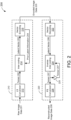
- FIG. 2 shows a block diagram of an example video transmission system 200, according to some implementations.
- the system 200 includes a video encoder 210 and a video decoder 220.
- the video encoder 210 and the video decoder 220 may be examples of the encoder 110 and decoder 120, respectively, of FIG. 1 .
- the video encoder 210 may be communicatively coupled to the video decoder 220 via a channel (such as the channel 130 of FIG. 1 ).
- the video encoder 210 is configured to encode raw image data 201, as encoded image data 205, for transmission to the decoder 220.
- a frame of raw image data 201 may include an array of pixel values (or multiple arrays of pixel values associated with different color channels) representing a digital image or frame of video captured or acquired by an image source (such as a camera or other image output device).
- the video encoder 210 may transmit a sequence of frames of encoded image data 205 each representing a respective image or frame of a digital video.
- the video decoder 220 is configured to decode the encoded image data 205, as reconstructed image data 208, for display on a display device (such as a television, computer monitor, smartphone, or any other device that includes an electronic display). More specifically, the video decoder 220 may reverse the encoding performed by the video encoder 210 so that the reconstructed image data 208 is substantially similar, if not identical, to the raw image data 201. In some aspects, the video decoder 220 may display or render a sequence of frames of reconstructed image data 208 on the display device.
- a display device such as a television, computer monitor, smartphone, or any other device that includes an electronic display. More specifically, the video decoder 220 may reverse the encoding performed by the video encoder 210 so that the reconstructed image data 208 is substantially similar, if not identical, to the raw image data 201. In some aspects, the video decoder 220 may display or render a sequence of frames of reconstructed image data 208 on the display device.
- the video encoder 210 is shown to include a latent space (LS) conversion component 212, an inter-coding component 214, and a vector encoding component 216.
- the LS conversion component 212 is configured to convert the raw image data 201 from the pixel domain to the latent domain.
- the LS conversion component 212 may transform the raw image data 201 into a tensor 202 of latent attributes based on a machine learning model.
- the LS conversion component 212 may perform an encoding operation associated with an autoencoder trained to reduce a dimensionality of the raw image data 201.
- the tensor 202 may be a compressed representation of the raw image data 201.
- the inter-coding component 214 is configured to produce a latent vector 203 based on the tensor 202 and latent information 204 associated with an image or video frame previously encoded by the encoder 210 (also referred to as "prior latent information").
- the prior latent information 204 may include latent attributes of the previous image or video frame.
- the inter-coding operation can be performed entirely in the latent domain.
- the inter-coding component 214 may combine the tensor 202 with the prior latent information 204 so that the latent vector 203 includes at least some latent attributes from each of the previous image and the current image.
- the resulting latent vector 203 may be smaller or more compressible than the tensor 202.
- the vector encoding component 216 is configured to encode the latent vector 203 as one or more codewords, of the encoded image data 205, according to one or more coding schemes. In some implementations, the vector encoding component 216 may perform entropy encoding (or other lossless or lossy compression) on the latent vector 203 to further reduce the amount of encoded image data 205 transmitted to the video decoder 220. In some aspects, the vector encoding component 216 also may recover prior latent information 204 to be used for encoding the next image or video frame received by the video encoder 210. In some implementations, the vector encoding component 216 may perform an inverse inter-coding operation on the latent vector 203 to produce the prior latent information 204.
- the video decoder 220 is shown to include a vector decoding component 222, an inverse inter-coding component 224, and a pixel space (PS) conversion component 226.
- the vector decoding component 222 is configured to recover a latent vector 206 from the encoded image data 205.
- the vector decoding component 222 may reverse the encoding performed by the vector encoding component 216.
- the vector decoding component 222 may decode the encoded image data 205, as the latent vector 206, according to the same coding schemes implemented by the vector encoding component 216.
- the latent vector 206 may be the same as the latent vector 203.
- the inverse inter-coding component 224 is configured to recover a tensor 207 of latent attributes based on the latent vector 206 and a tensor 207' previously recovered by the inverse inter-coding component 224 (also referred to as the "previous tensor").
- the previous tensor 207' may include latent attributes of the previous image or video frame decoded by the video decoder 220.
- the previous tensor 207' may be the same as the prior latent information 204 used by the video encoder 210 to encode the current image or video frame.
- the inverse inter-coding component 224 may combine the latent vector 206 with the previous tensor 207' so that the resulting tensor 207 includes at least some latent attributes from each of the previous image and the current image.
- the resulting tensor 207 may be stored in a buffer 225, as a previous tensor 207', to be used for decoding the next image or video frame.
- the PS conversion component 226 is configured to convert the tensor 207 from the latent domain back to the pixel domain.
- the PS conversion component 226 may transform the tensor 207 into the reconstructed image data 208 based on a machine learning model.
- the PS conversion component 226 may perform a decoding operation associated with an autoencoder trained to reconstruct the raw image data 201 from the tensor 207.
- the reconstructed image data 208 may be substantially similar, if not identical, to the raw image data 201.
- the reconstructed image data 208 may be further displayed or rendered as a digital image on an electronic display (not shown for simplicity).
- the LS conversion component 212, the inter-frame coding component 214, the inverse inter-coding component 224, and the PS conversion component 226 may be collectively trained as an autoencoder that reproduces, at its output, the same image received at its input.
- the autoencoder of the present implementations is trained to reproduce each output image based on latent attributes of the current input image and latent attributes of a previous input image. Due to the inter-coding operations performed in the latent domain (such as by the inter-coding component 214 and the inverse inter-coding component 224), the output layer of the LS conversion component 212 is different than the input layer of the PS conversion component 224. Accordingly, the tensor 207 may be different than the tensor 202 for the same image.
- FIG. 3 shows a block diagram of an example video encoding system 300, according to some implementations.
- the video encoding system 300 may be one example of the video encoder 210 of FIG. 2 .
- the video encoding system 300 is configured to encode an input image 301 as a vector 304 of latent attributes (also referred to as a "latent vector") based, at least in part, on latent attributes of an input image previously encoded by the video encoding system 300 (also referred to as the "previous input image").
- the input image 301 may be one example of the raw image data 201 and the latent vector 304 may be one example of the latent vector 203.
- the video encoding system 300 includes an analysis transform 310, an inter-coding transform 320, and an inverse inter-coding transform 330.
- the analysis transform 310 transforms the input image 301 into a tensor 302 of latent attributes associated with the input image 301 (also referred to as an "encoding tensor") based on a neural network model.
- the analysis transform 310 converts the input image 301 from the pixel domain to the latent domain.
- the analysis transform 310 may be one example of the LS conversion component 212.
- the analysis transform 310 may include multiple layers of a convolutional neural network (CNN) trained to reduce a dimensionality of the input image 301.
- the input image 301 may be represented by a three-dimensional array of pixel values having a particular height ( h i ), width ( w i ), and depth ( d i ), depending on the image format.
- the CNN produces the encoding tensor 302 at its output as a result of processing the input image 301 through various convolutional layers, pooling layers, or any combination thereof, that reduce the dimensionality of the input image 301.
- the encoding tensor 302 at the output of the CNN is a compressed representation of the input image 301.
- the encoding tensor 302 may be a three-dimensional tensor ( h, w, d a ) having a height h, width w, and depth d a , where h ⁇ h i , w ⁇ w i , and d a > d i .
- the video encoding system 300 combines the encoding tensor 302 with a tensor 306 of latent attributes associated with the previous input image (also referred to as a "decoding tensor") to produce a reconstructed tensor 303.
- the decoding tensor 306 may be one example of the prior latent information 204.
- the decoding tensor 306 may be a three-dimensional tensor ( h, w, d s ) having the same height h and width w as the encoding tensor 302, with a depth d s that is the same or different than the depth d a of the encoding tensor 302, and the reconstructed tensor 303 may be a concatenation of the encoding tensor 302 and the decoding tensor 306.
- the inter-coding transform 320 transforms the reconstructed tensor 303 into the latent vector 304 by reducing a dimensionality of the reconstructed tensor 303.
- the inter-coding transform 320 may be any linear or nonlinear transform that maintains the height h and width w of the reconstructed tensor 303 while reducing its depth d r 1 .
- the latent vector 304 may be a three-dimensional tensor ( h, w, d l ) having the same height h and width w as the reconstructed tensor 303, and a depth d l that is less than the depth d r 1 of the reconstructed tensor 303.
- the inter-coding transform 320 may include one or more layers of a CNN trained to transform the reconstructed tensor 303 into a latent vector 304 that is smaller or more compressible than the encoding tensor 302.
- the latent vector 304 may be further entropy encoded and transmitted, over a communication channel, to a video decoder (not shown for simplicity).
- the video encoding system 300 may use the latent vector 304, in a recursive feedback loop, to encode the next input image in the sequence of images. For example, the video encoding system 300 may combine the latent vector 304 with the decoding tensor 306 to produce another reconstructed tensor 305. In some implementations, the reconstructed tensor 305 may be a concatenation of the latent vector 304 and the decoding tensor 306.
- the inverse inter-coding transform 330 transforms the reconstructed tensor 305 into a new decoding tensor 306', which includes latent attributes of the current input image 301, by reducing a dimensionality of the reconstructed tensor 305.
- the inverse inter-coding transform 330 may be any linear or nonlinear transform that maintains the height h and width w of the reconstructed tensor 305 while reducing its depth d r 2 . As a result, the depth d s of the decoding tensor 306' is less than the depth d r 2 of the reconstructed tensor 305.
- the inverse inter-coding transform 330 may include one or more layers of a CNN trained to transform the reconstructed tensor 305 into a decoding tensor 306' that can be converted back to the pixel domain (as the original input image 301).
- the new decoding tensor 306' may be stored in a tensor buffer 340, as a decoding tensor 306, to be used for encoding the next input image.
- FIG. 4 shows an example inter-coding operation 400 that can be performed in a latent domain, according to some implementations.
- the example operation 400 may be performed by a video encoder (such as the video encoder 210 of FIG. 2 or the video encoding system 300 of FIG. 3 ) to produce a latent vector 408 based on an encoding tensor 402 and a decoding tensor 404.
- the encoding tensor 402, decoding tensor 404, and latent vector 408 may be examples of the encoding tensor 302, decoding tensor 306, and latent vector 304, respectively, of FIG. 3 .
- the tensors 402 and 404 may have different depths.
- the encoding tensor 402 is combined with the decoding tensor 404 to produce a reconstructed tensor 406.
- the reconstructed tensor 406 may be one example of the reconstructed tensor 303 of FIG. 3 .
- the tensors 402 and 404 are concatenated in a manner which preserves their height h and width w while combining their depths d a and d s .
- An inter-coding transform 410 converts the reconstructed tensor 406 into the latent vector 408.
- the inter-coding transform 410 may be one example of the inter-coding transform 320 of FIG. 3 .
- the inter-coding transform 410 may include one or more layers of a CNN trained to reduce a dimensionality of the reconstructed tensor 406 to produce a latent vector 408 that is smaller or more compressible than the encoding tensor 402.
- the latent vector 408 may have any depth d l less than that of the reconstructed tensor 406 ( d l ⁇ d r 1 ) . In some implementations, the latent vector 408 may have the same depth as the encoding tensor 402 or the decoding tensor 404.
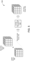
- FIG. 5 shows an example inverse inter-coding operation 500 that can be performed in a latent domain, according to some implementations.
- the example operation 500 may be performed by a video encoder (such as the video encoder 210 of FIG. 2 or the video encoding system 300 of FIG. 3 ), or a video decoder (such as the video decoder 220 of FIG. 2 ), to recover a decoding tensor 504 based on the latent vector 408 and the decoding tensor 404 of FIG. 4 .
- the decoding tensor 504 may be one example of the decoding tensor 306' of FIG. 3 .
- the latent vector 408 is combined with the decoding tensor 404 to produce a reconstructed tensor 502.
- the reconstructed tensor 502 may be one example of the reconstructed tensor 305 of FIG. 3 . As shown in FIG.
- the latent vector 408 and the decoding tensor 404 are concatenated in a manner which preserves their height h and width w while combining their depths d l and d s .
- An inverse inter-coding transform 510 converts the reconstructed tensor 502 into the decoding tensor 504.
- the inverse inter-coding transform 510 may be one example of the inverse inter-coding transform 330 of FIG. 3 .
- the inverse inter-coding transform 510 may include one or more layers of a CNN trained to reduce a dimensionality of the reconstructed tensor 502 to produce a decoding tensor 504 that can be converted back to the pixel domain (as the original input image).
- the decoding tensor 504 has the same dimensions as the decoding tensor 404.
- FIG. 6 shows a block diagram of an example video decoding system 600, according to some implementations.
- the video decoding system 600 may be one example of the video decoder 220 of FIG. 2 .
- the video decoding system 600 is configured to decode a latent vector 602 as an output image 608 based, at least in part, on latent attributes of an output image previously decoded by the video decoding system 600 (also referred to as the "previous output image").
- the latent vector 602 may be one example of the latent vector 206 and the output image 608 may be one example of the reconstructed image data 208.
- the latent vector 602 may be a three-dimensional tensor ( h, w, d l ) having a height h, width w, and depth d l .
- the video decoding system 600 combines the latent vector 602 with a tensor 606 of latent attributes associated with the previous output image (also referred to as a "decoding tensor") to produce a reconstructed tensor 604.
- the decoding tensor 606 may be one example of the tensor 207'.
- the decoding tensor 606 may be a three-dimensional tensor (h, w, d s ) having the same height h and width w as the latent vector 602, with a depth d s that is the same or different than the depth d l of the latent vector 602, and the reconstructed tensor 604 may be a concatenation of the latent vector 602 and the decoding tensor 606 (such as described with reference to FIG. 5 ).
- the video decoding system 600 includes an inverse inter-coding transform 610 and a synthesis transform 620.
- the inverse inter-coding transform 610 transforms the reconstructed tensor 604 into a new decoding tensor 606', which includes latent attributes of the current output image 608, by reducing a dimensionality of the reconstructed tensor 604 (such as described with reference to FIG. 5 ).
- the inverse inter-coding transform 610 may be the same as the inverse inter-coding transform 330 of FIG. 3 .
- the inverse inter-coding transform 610 be any linear or nonlinear transform that maintains the height h and width w of the reconstructed tensor 604 while reducing its depth d r .
- the depth d s of the decoding tensor 606' is less than the depth d r of the reconstructed tensor 604.
- the new decoding tensor 606' may be stored in a tensor buffer 630, as a decoding tensor 606, to be used for decoding the next latent vector.
- the synthesis transform 620 transforms the decoding tensor 606' into the output image 608 based on a neural network model.
- the synthesis transform 620 converts the decoding tensor 606' from the latent domain to the pixel domain.
- the synthesis transform 620 may be one example of the PS conversion component 226.
- the synthesis transform 620 may include multiple layers of a CNN trained to up-sample the decoding tensor 606'.
- the CNN may reconstruct the output image 608 as a result of processing the decoding tensor 606' through various convolutional layers, pooling layers, or any combination thereof, that increases the dimensionality of the decoding tensor 606'.
- the output image 608 is a decompressed representation of the decoding tensor 606'.
- the output image 608 may be represented by a three-dimensional array of pixel values having a particular height ( h o ), width (w o ), and depth ( d o ), where h o > h, w o > w , and d o ⁇ d s .
- the video encoder 700 may include a data interface 710, a processing system 720, and a memory 730.
- the data interface 710 is configured to receive image data from an image source and output a vector of latent attributes, associated with the image data, over the communication channel.
- the data interface 710 may include an image source interface (I/F) 712 to communicate with the image source and a channel interface 714 to communicate via the communication channel.
- the image source interface 712 may receive a sequence of images from the image source, and the channel interface 714 may transmit the latent vector, over the communication channel, to a video decoder.
- the processing system 720 may include any suitable one or more processors capable of executing scripts or instructions of one or more software programs stored in the encoder 700 (such as in memory 730). For example, the processing system 720 may execute the LS conversion SW module 734 to encode a first image, in the sequence of images, as a tensor of latent attributes associated with the first image based on a machine learning model. The processing system 720 may further execute the inter-coding SW module 736 to perform an inter-coding operation that produces the vector of latent attributes based on the tensor of latent attributes associated with the first image and a tensor of latent attributes associated with a second image, in the sequence of images, received prior to the first image.
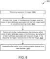
- the video encoder receives a sequence of images (810).
- the video encoder encodes a first image, in the sequence of images, as a first tensor of latent attributes associated with the first image based on a machine learning model (820).
- the video encoder performs a first inter-coding operation that produces a first vector of latent attributes based on the first tensor and a tensor of latent attributes associated with a second image, in the sequence of images, received prior to the first image (830).
- the performing of the first inter-coding operation may include generating a first reconstructed tensor based on the first tensor and the tensor of latent attributes associated with the second image; and encoding the first reconstructed tensor as the first vector based on an inter-coding transform that reduces a dimensionality of the first reconstructed tensor.
- the video encoder further transmits the first vector, over a communication channel, to a video decoder (840).
- the first tensor, the tensor of latent attributes associated with the second image, the first reconstructed tensor, and the first vector may each have a respective height, width, and depth.
- the first vector may have the same height and the same width as each of the first reconstructed tensor, the first tensor, and the tensor of latent attributes associated with the second image.
- the depth of the first vector may be less than the depth of the first reconstructed tensor.
- the generating of the first reconstructed tensor may include concatenating the first tensor and the tensor of latent attributes associated with the second image so that the depth of the first reconstructed tensor is equal to the sum of the depths of the first tensor and the tensor of latent attributes associated with the second image.
- the video encoder may further perform an inverse inter-coding operation that produces a second tensor of latent attributes associated with the first image based on the first vector and the tensor of latent attributes associated with the second image; encode a third image, in the sequence of images, as a tensor of latent attributes associated with the third image based on the machine learning model; perform a second inter-coding operation that produces a second vector of latent attributes based on the second tensor and the tensor of latent attributes associated with the third image; and transmit the second vector, over the communication channel, to the video decoder.
- the performing of the second inter-coding operation may include generating a second reconstructed tensor based on the second tensor and the tensor of latent attributes associated with the third image; and encoding the second reconstructed tensor as the second vector based on the inter-coding transform.
- the performing of the inverse inter-coding operation may include generating a second reconstructed tensor based on the first vector and the tensor of latent attributes associated with the second image; and decoding the second reconstructed tensor as the second tensor based on an inverse inter-coding transform that reduces a dimensionality of the second reconstructed tensor.
- the generating of the second reconstructed tensor may include concatenating the first vector and the tensor of latent attributes associated with the second image so that the depth of the second reconstructed tensor is equal to the sum of the depths of the first vector and the tensor of latent attributes associated with the second image.
- a software module may reside in RAM memory, flash memory, ROM memory, EPROM memory, EEPROM memory, registers, hard disk, a removable disk, a CD-ROM, or any other form of storage medium known in the art.
- An exemplary storage medium is coupled to the processor such that the processor can read information from, and write information to, the storage medium. In the alternative, the storage medium may be integral to the processor.
Landscapes
- Engineering & Computer Science (AREA)
- Multimedia (AREA)
- Signal Processing (AREA)
- Physics & Mathematics (AREA)
- Theoretical Computer Science (AREA)
- Artificial Intelligence (AREA)
- Evolutionary Computation (AREA)
- General Physics & Mathematics (AREA)
- Biomedical Technology (AREA)
- Life Sciences & Earth Sciences (AREA)
- Health & Medical Sciences (AREA)
- Biophysics (AREA)
- Computational Linguistics (AREA)
- Data Mining & Analysis (AREA)
- General Health & Medical Sciences (AREA)
- Molecular Biology (AREA)
- Computing Systems (AREA)
- General Engineering & Computer Science (AREA)
- Mathematical Physics (AREA)
- Software Systems (AREA)
- Compression Or Coding Systems Of Tv Signals (AREA)
Abstract
Description
- The present implementations relate generally to video coding, and specifically to inter-coding transforms for autoencoders.
- A digital video is a sequence of digital images (or "frames") that can be displayed or otherwise rendered in succession (such as by a video playback device). Each digital image can be represented by an array of pixel values (or multiple arrays of pixel values associated with different channels). Some video playback devices may receive the sequence of images, over a communication channel (such as a wired or wireless medium), from a source device (such as an image capture device or video data repository). Due to bandwidth limitations of the communication channel, digital image data is often encoded or compressed prior to transmission by the source device. Data compression is a technique for encoding information into smaller units of data. As such, data compression can be used to reduce the bandwidth or overhead needed to store or transmit video frames over the communication channel.
- Example video compression techniques include "intra-frame" coding and "inter-frame" coding. Intra-frame coding can be used to encode individual frames of video as independent images (rather than a temporal sequence of images). In other words, the pixel values of an intra-coded video frame can be decoded independently, or without information from any other frames of video. However, adjacent frames of video (such as images displayed successively in time) are likely to be the same or substantially similar in appearance. Thus, inter-frame coding (also referred to as "inter-coding" or "differential coding") can be used to transmit only the differences between successive video frames (also referred to as "residuals"). In other words, a residual frame of video must be combined with one or more previous video frames to recover the pixel values to be displayed for the current video frame.
- Some modern video coding systems (such as autoencoders) use machine learning to achieve greater levels of data compression. However, machine learning models require significant processing and memory overhead, particularly for encoding residual frames. Thus, new video coding techniques are needed to leverage machine learning for data compression while reducing overall resource consumption.
- This Summary is provided to introduce in a simplified form a selection of concepts that are further described below in the Detailed Description. This Summary is not intended to identify key features or essential features of the claimed subject matter, nor is it intended to limit the scope of the claimed subject matter.
- One innovative aspect of the subject matter of this disclosure can be implemented in a method of video coding. The method includes steps of receiving a sequence of images; encoding a first image, in the sequence of images, as a tensor of latent attributes associated with the first image based on a machine learning model; performing an inter-coding operation that produces a vector of latent attributes based on the tensor of latent attributes associated with the first image and a tensor of latent attributes associated with a second image, in the sequence of images, received prior to the first image; and transmitting the vector, over a communication channel, to a video decoder.
- Another innovative aspect of the subject matter of this disclosure can be implemented in a video encoder that includes a processing system and a memory. The memory stores instructions that, when executed by the processing system, cause the video encoder to receive a sequence of images; encode a first image, in the sequence of images, as a tensor of latent attributes associated with the first image based on a machine learning model; perform an inter-coding operation that produces a vector of latent attributes based on the tensor of latent attributes associated with the first image and a tensor of latent attributes associated with a second image, in the sequence of images, received prior to the first image; and transmit the vector, over a communication channel, to a video decoder.
- The present implementations are illustrated by way of example and are not intended to be limited by the figures of the accompanying drawings.
-
FIG. 1 shows an example communication system for encoding and decoding data. -
FIG. 2 shows a block diagram of an example video transmission system, according to some implementations. -
FIG. 3 shows a block diagram of an example video encoding system, according to some implementations. -
FIG. 4 shows an example inter-coding operation that can be performed in a latent domain, according to some implementations. -
FIG. 5 shows an example inverse inter-coding operation that can be performed in a latent domain, according to some implementations. -
FIG. 6 shows a block diagram of an example video decoding system, according to some implementations. -
FIG. 7 shows a block diagram of an example video encoder, according to some implementations. -
FIG. 8 shows an illustrative flowchart depicting an example operation for video coding, according to some implementations. - In the following description, numerous specific details are set forth such as examples of specific components, circuits, and processes to provide a thorough understanding of the present disclosure. The term "coupled" as used herein means connected directly to or connected through one or more intervening components or circuits. The terms "electronic system" and "electronic device" may be used interchangeably to refer to any system capable of electronically processing information. Also, in the following description and for purposes of explanation, specific nomenclature is set forth to provide a thorough understanding of the aspects of the disclosure. However, it will be apparent to one skilled in the art that these specific details may not be required to practice the example embodiments. In other instances, well-known circuits and devices are shown in block diagram form to avoid obscuring the present disclosure. Some portions of the detailed descriptions which follow are presented in terms of procedures, logic blocks, processing and other symbolic representations of operations on data bits within a computer memory.
- These descriptions and representations are the means used by those skilled in the data processing arts to most effectively convey the substance of their work to others skilled in the art. In the present disclosure, a procedure, logic block, process, or the like, is conceived to be a self-consistent sequence of steps or instructions leading to a desired result. The steps are those requiring physical manipulations of physical quantities. Usually, although not necessarily, these quantities take the form of electrical or magnetic signals capable of being stored, transferred, combined, compared, and otherwise manipulated in a computer system. It should be borne in mind, however, that all of these and similar terms are to be associated with the appropriate physical quantities and are merely convenient labels applied to these quantities.
- Unless specifically stated otherwise as apparent from the following discussions, it is appreciated that throughout the present application, discussions utilizing the terms such as "accessing," "receiving," "sending," "using," "selecting," "determining," "normalizing," "multiplying," "averaging," "monitoring," "comparing," "applying," "updating," "measuring," "deriving" or the like, refer to the actions and processes of a computer system, or similar electronic computing device, that manipulates and transforms data represented as physical (electronic) quantities within the computer system's registers and memories into other data similarly represented as physical quantities within the computer system memories or registers or other such information storage, transmission or display devices.
- In the figures, a single block may be described as performing a function or functions; however, in actual practice, the function or functions performed by that block may be performed in a single component or across multiple components, and/or may be performed using hardware, using software, or using a combination of hardware and software. To clearly illustrate this interchangeability of hardware and software, various illustrative components, blocks, modules, circuits, and steps have been described below generally in terms of their functionality. Whether such functionality is implemented as hardware or software depends upon the particular application and design constraints imposed on the overall system. Skilled artisans may implement the described functionality in varying ways for each particular application, but such implementation decisions should not be interpreted as causing a departure from the scope of the present disclosure. Also, the example input devices may include components other than those shown, including well-known components such as a processor, memory and the like.
- The techniques described herein may be implemented in hardware, software, firmware, or any combination thereof, unless specifically described as being implemented in a specific manner. Any features described as modules or components may also be implemented together in an integrated logic device or separately as discrete but interoperable logic devices. If implemented in software, the techniques may be realized at least in part by a non-transitory processor-readable storage medium including instructions that, when executed, performs one or more of the methods described above. The non-transitory processor-readable data storage medium may form part of a computer program product, which may include packaging materials.
- The non-transitory processor-readable storage medium may comprise random access memory (RAM) such as synchronous dynamic random-access memory (SDRAM), read only memory (ROM), non-volatile random access memory (NVRAM), electrically erasable programmable read-only memory (EEPROM), FLASH memory, other known storage media, and the like. The techniques additionally, or alternatively, may be realized at least in part by a processor-readable communication medium that carries or communicates code in the form of instructions or data structures and that can be accessed, read, and/or executed by a computer or other processor.
- The various illustrative logical blocks, modules, circuits and instructions described in connection with the embodiments disclosed herein may be executed by one or more processors (or a processing system). The term "processor," as used herein may refer to any general-purpose processor, special-purpose processor, conventional processor, controller, microcontroller, and/or state machine capable of executing scripts or instructions of one or more software programs stored in memory.
- As described above, some modern video coding systems (such as autoencoders) utilize machine learning to achieve greater levels of data compression. Machine learning is a technique for improving the ability of a computer system or application to perform a specific task. During a training phase, a machine learning system is provided with multiple "answers" and a large volume of raw input data. The machine learning system analyzes the input data to learn a set of rules (also referred to as the "machine learning model") that can be used to map the input data to the answers. During an inferencing phase, the machine learning system uses the trained machine learning model to infer answers from new input data.
- Deep learning is a particular form of machine learning in which the inferencing and training phases are performed over multiple layers. Deep learning architectures are often referred to as "artificial neural networks" due to the manner in which information is processed (similar to a biological nervous system). For example, each layer of an artificial neural network may be composed of one or more "neurons." Each layer of neurons may perform a different transformation on the output data from a preceding layer so that the final output of the neural network results in the desired inferences. The set of transformations associated with the various layers of the network is referred to as a "neural network model."
- An autoencoder is a type of artificial neural network that is well suited for image compression. For example, an autoencoder can be trained to reproduce, at its output, the same image received at its input. A bottleneck is imposed between the input layer and the output layer of the neural network, which reduces a dimensionality of the outputs at the intermediate layers. As a result of the bottleneck, the autoencoder is forced to learn a compressed representation (or "latent attributes") of the input image. Thus, autoencoder architectures generally include an encoder trained to convert a frame of image data into a lower-dimensional tensor or vector of latent attributes, and a decoder trained to reconstruct the original frame of image data from the tensor or vector of latent attributes.
- In a video coding system, the latent attributes represent the compressed image data that is sent by a video encoder, over a communication channel, to a video decoder. For example, the video encoder may implement an encoding portion of an autoencoder, and the video decoder may implement a decoding portion of the autoencoder. However, when using an autoencoder to compress a residual frame of image data (as a result of inter-frame coding), the video encoder must also implement the decoding portion of the autoencoder to recover the previous video frame (from a residual frame of latent attributes) that will be used for inter-coding the next residual frame.
- Performing both the encoding and decoding operations of an autoencoder requires substantial processing and memory overhead which may not be practical (or feasible) to implement in some video encoders. However, aspects of the present disclosure recognize that inter-frame coding can be more efficiently integrated with autoencoders by moving the inter-coding framework from the pixel domain to the latent domain. As used herein, the term "latent domain" refers to any data associated with, or operations performed on, latent attributes of an input image (such as after reducing a dimensionality of the input image by an autoencoder). By contrast, the term "pixel domain" refers to any data associated with, or operations performed on, the pixel values of an input image (such as prior to reducing the dimensionality of the input image).
- Various aspects relate generally to video coding, and more particularly, to autoencoders that support inter-frame coding in the latent domain. A video encoder may convert a frame of video from the pixel domain to the latent domain based on a machine learning model. For example, the machine learning model may be trained to transform the video frame into a tensor of latent attributes (also referred to as an "encoding tensor"). In some aspects, the video encoder may combine the encoding tensor with a tensor of latent attributes associated with a previously-encoded video frame (also referred to as a "decoding tensor") and transform the resulting tensor into a vector that includes latent attributes from both the current video frame and the previous video frame (also referred to as a "latent vector") based on an inter-coding transform. More specifically, the inter-coding transform may reduce a dimensionality of the combined tensor so that the latent vector is smaller or more compressible than the encoding tensor. The video encoder further transmits the latent vector, over a communication channel, to a video decoder.
- In some aspects, the video decoder may combine the latent vector with the decoding tensor and transform the resulting tensor into a tensor of latent attributes associated with the current video frame (also referred to as a "new decoding tensor") based on an inverse inter-coding transform. More specifically, the inverse inter-coding transform may reduce a dimensionality of the combined tensor so that the new decoding tensor can be converted from the latent domain back to the pixel domain by a machine learning model. For example, the machine learning model may be trained to reconstruct the current video frame from the latent attributes included in the new decoding tensor. In some implementations, the video decoder may decode (or decompress) the new decoding tensor as the current video frame based on the machine learning model. In some other implementations, the video encoder may use the new decoding tensor to repeat the inter-coding operation for a new video frame (such as the next video frame in sequence).
- Particular implementations of the subject matter described in this disclosure can be implemented to realize one or more of the following potential advantages. Aspects of the present disclosure combine the benefits of inter-frame coding and autoencoders, in an efficient manner, to reduce the size of compressed image data. For example, by performing inter-frame coding in the latent domain associated with an autoencoder, video encoders of the present implementations can encode latent vectors based on previous video frames without having to transform the latent attributes of each video frame back into the pixel domain. Moreover, the inter-coding transform and the inverse inter-coding transform of the present implementations may be substantially smaller than the neural network layers of an autoencoder needed convert the latent attributes from the latent domain to the pixel domain. Thus, compared to existing inter-frame coding techniques, aspects of the present disclosure may significantly reduce the processing and memory overhead of the video encoder.
-
FIG. 1 shows anexample communication system 100 for encoding and decoding data. Thecommunication system 100 includes anencoder 110 and adecoder 120. In some implementations, theencoder 110 anddecoder 120 may be provided in respective communication devices such as, for example, computers, switches, routers, hubs, gateways, cameras, displays, or other devices capable of transmitting or receiving communication signals. In some other implementations, theencoder 110 anddecoder 120 may be included in the same device or system. - The
encoder 110 receivesinput data 102 to be transmitted or stored via achannel 130. For example, thechannel 130 may include a wired or wireless communication medium that facilities communications between theencoder 110 and thedecoder 120. Alternatively, or in addition, thechannel 130 may include a data storage medium. In some aspects, theencoder 110 may be configured to compress the size of theinput data 102 to accommodate the bandwidth, storage, or other resource limitations associated with thechannel 130. For example, theencoder 110 may encode each unit ofinput data 102 as a respective "codeword" that can be transmitted or stored over the channel 130 (as encoded data 104). Thedecoder 120 is configured to receive the encodeddata 104, via thechannel 130, and decode the encodeddata 104 asoutput data 106. For example, thedecoder 120 may decompress or otherwise reverse the compression performed by theencoder 110 so that theoutput data 106 is substantially similar, if not identical, to theoriginal input data 102. - Data compression techniques can be generally categorized as "lossy" or "lossless." Lossy data compression may result in some loss of information between the encoding and decoding steps. As a result, the
output data 106 may be different than theinput data 102. Example lossy compression techniques include, among other examples, transform coding (such as through application of a spatial-frequency transform) and quantization (such as through application of a quantization matrix). In contrast, lossless data compression does not result in any loss of information between the encoding and decoding steps as long as thechannel 130 does not introduce errors into the encodeddata 104. As a result, theoutput data 106 is identical to theinput data 102. Example lossless compression techniques include, among other examples, entropy encoding (such as arithmetic coding, Huffman coding, or Golomb coding) and run-length encoding (RLE). - In some implementations, the
encoder 110 and thedecoder 120 may utilize machine learning to achieve even greater data compression. As described above, machine learning is a technique for improving the ability of a computer system or application to perform a specific task. During a training phase, a machine learning system is provided with multiple "answers" and a large volume of raw input data. The machine learning system analyzes the input data to learn a set of rules (also referred to as the "machine learning model") that can be used to map the input data to the answers. During an inferencing phase, the machine learning system uses the trained machine learning model to infer answers from new input data. - Deep learning is a particular form of machine learning in which the inferencing and training phases are performed over multiple layers. Deep learning architectures are often referred to as "artificial neural networks" due to the manner in which information is processed (similar to a biological nervous system). For example, each layer of an artificial neural network may be composed of one or more "neurons." Each layer of neurons may perform a different transformation on the output data from a preceding layer so that the final output of the neural network results in the desired inferences. The set of transformations associated with the various layers of the network is referred to as a "neural network model."
- An autoencoder is a type of artificial neural network that is well suited for image compression. For example, an autoencoder can be trained to reproduce, at its output, the same image received at its input. A bottleneck is imposed between the input layer and the output layer of the neural network, which reduces a dimensionality of the outputs at the intermediate layers. As a result of the bottleneck, the autoencoder is forced to learn a compressed representation (or "latent attributes") of the input image. Thus, autoencoder architectures generally include an encoder trained to convert a frame of image data into a lower-dimensional tensor or vector of latent attributes, and a decoder trained to reconstruct the original frame of image data from the tensor or vector of latent attributes.
-
FIG. 2 shows a block diagram of an examplevideo transmission system 200, according to some implementations. Thesystem 200 includes avideo encoder 210 and avideo decoder 220. In some implementations, thevideo encoder 210 and thevideo decoder 220 may be examples of theencoder 110 anddecoder 120, respectively, ofFIG. 1 . Thus, thevideo encoder 210 may be communicatively coupled to thevideo decoder 220 via a channel (such as thechannel 130 ofFIG. 1 ). - The
video encoder 210 is configured to encoderaw image data 201, as encodedimage data 205, for transmission to thedecoder 220. For example, a frame ofraw image data 201 may include an array of pixel values (or multiple arrays of pixel values associated with different color channels) representing a digital image or frame of video captured or acquired by an image source (such as a camera or other image output device). In some aspects, thevideo encoder 210 may transmit a sequence of frames of encodedimage data 205 each representing a respective image or frame of a digital video. - The
video decoder 220 is configured to decode the encodedimage data 205, as reconstructedimage data 208, for display on a display device (such as a television, computer monitor, smartphone, or any other device that includes an electronic display). More specifically, thevideo decoder 220 may reverse the encoding performed by thevideo encoder 210 so that thereconstructed image data 208 is substantially similar, if not identical, to theraw image data 201. In some aspects, thevideo decoder 220 may display or render a sequence of frames of reconstructedimage data 208 on the display device. - The
video encoder 210 is shown to include a latent space (LS)conversion component 212, aninter-coding component 214, and avector encoding component 216. TheLS conversion component 212 is configured to convert theraw image data 201 from the pixel domain to the latent domain. In some implementations, theLS conversion component 212 may transform theraw image data 201 into atensor 202 of latent attributes based on a machine learning model. For example, theLS conversion component 212 may perform an encoding operation associated with an autoencoder trained to reduce a dimensionality of theraw image data 201. As a result, thetensor 202 may be a compressed representation of theraw image data 201. - The
inter-coding component 214 is configured to produce alatent vector 203 based on thetensor 202 andlatent information 204 associated with an image or video frame previously encoded by the encoder 210 (also referred to as "prior latent information"). In some implementations, the priorlatent information 204 may include latent attributes of the previous image or video frame. Thus, the inter-coding operation can be performed entirely in the latent domain. For example, theinter-coding component 214 may combine thetensor 202 with the priorlatent information 204 so that thelatent vector 203 includes at least some latent attributes from each of the previous image and the current image. In some implementations, the resultinglatent vector 203 may be smaller or more compressible than thetensor 202. - The
vector encoding component 216 is configured to encode thelatent vector 203 as one or more codewords, of the encodedimage data 205, according to one or more coding schemes. In some implementations, thevector encoding component 216 may perform entropy encoding (or other lossless or lossy compression) on thelatent vector 203 to further reduce the amount of encodedimage data 205 transmitted to thevideo decoder 220. In some aspects, thevector encoding component 216 also may recover priorlatent information 204 to be used for encoding the next image or video frame received by thevideo encoder 210. In some implementations, thevector encoding component 216 may perform an inverse inter-coding operation on thelatent vector 203 to produce the priorlatent information 204. - The
video decoder 220 is shown to include avector decoding component 222, an inverseinter-coding component 224, and a pixel space (PS)conversion component 226. Thevector decoding component 222 is configured to recover alatent vector 206 from the encodedimage data 205. In some implementations, thevector decoding component 222 may reverse the encoding performed by thevector encoding component 216. For example, thevector decoding component 222 may decode the encodedimage data 205, as thelatent vector 206, according to the same coding schemes implemented by thevector encoding component 216. As a result, thelatent vector 206 may be the same as thelatent vector 203. - The inverse
inter-coding component 224 is configured to recover atensor 207 of latent attributes based on thelatent vector 206 and a tensor 207' previously recovered by the inverse inter-coding component 224 (also referred to as the "previous tensor"). For example, the previous tensor 207' may include latent attributes of the previous image or video frame decoded by thevideo decoder 220. In some implementations, the previous tensor 207' may be the same as the priorlatent information 204 used by thevideo encoder 210 to encode the current image or video frame. The inverseinter-coding component 224 may combine thelatent vector 206 with the previous tensor 207' so that the resultingtensor 207 includes at least some latent attributes from each of the previous image and the current image. In some implementations, the resultingtensor 207 may be stored in abuffer 225, as a previous tensor 207', to be used for decoding the next image or video frame. - The
PS conversion component 226 is configured to convert thetensor 207 from the latent domain back to the pixel domain. In some implementations, thePS conversion component 226 may transform thetensor 207 into thereconstructed image data 208 based on a machine learning model. For example, thePS conversion component 226 may perform a decoding operation associated with an autoencoder trained to reconstruct theraw image data 201 from thetensor 207. As a result, thereconstructed image data 208 may be substantially similar, if not identical, to theraw image data 201. In some implementations, thereconstructed image data 208 may be further displayed or rendered as a digital image on an electronic display (not shown for simplicity). - In some aspects, the
LS conversion component 212, theinter-frame coding component 214, the inverseinter-coding component 224, and thePS conversion component 226 may be collectively trained as an autoencoder that reproduces, at its output, the same image received at its input. However, unlike existing autoencoders, the autoencoder of the present implementations is trained to reproduce each output image based on latent attributes of the current input image and latent attributes of a previous input image. Due to the inter-coding operations performed in the latent domain (such as by theinter-coding component 214 and the inverse inter-coding component 224), the output layer of theLS conversion component 212 is different than the input layer of thePS conversion component 224. Accordingly, thetensor 207 may be different than thetensor 202 for the same image. -
FIG. 3 shows a block diagram of an examplevideo encoding system 300, according to some implementations. In some implementations, thevideo encoding system 300 may be one example of thevideo encoder 210 ofFIG. 2 . More specifically, thevideo encoding system 300 is configured to encode aninput image 301 as avector 304 of latent attributes (also referred to as a "latent vector") based, at least in part, on latent attributes of an input image previously encoded by the video encoding system 300 (also referred to as the "previous input image"). With reference toFIG. 2 , theinput image 301 may be one example of theraw image data 201 and thelatent vector 304 may be one example of thelatent vector 203. - The
video encoding system 300 includes ananalysis transform 310, aninter-coding transform 320, and an inverseinter-coding transform 330. The analysis transform 310 transforms theinput image 301 into atensor 302 of latent attributes associated with the input image 301 (also referred to as an "encoding tensor") based on a neural network model. In other words, the analysis transform 310 converts theinput image 301 from the pixel domain to the latent domain. With reference toFIG. 2 , the analysis transform 310 may be one example of theLS conversion component 212. - In some implementations, the analysis transform 310 may include multiple layers of a convolutional neural network (CNN) trained to reduce a dimensionality of the
input image 301. For example, theinput image 301 may be represented by a three-dimensional array of pixel values having a particular height (hi ), width (wi ), and depth (di ), depending on the image format. The CNN produces theencoding tensor 302 at its output as a result of processing theinput image 301 through various convolutional layers, pooling layers, or any combination thereof, that reduce the dimensionality of theinput image 301. Thus, theencoding tensor 302 at the output of the CNN is a compressed representation of theinput image 301. In some implementations, theencoding tensor 302 may be a three-dimensional tensor (h, w, da) having a height h, width w, and depth da , where h < hi, w < wi , and da > di . - The
video encoding system 300 combines theencoding tensor 302 with atensor 306 of latent attributes associated with the previous input image (also referred to as a "decoding tensor") to produce areconstructed tensor 303. With reference toFIG. 2 , thedecoding tensor 306 may be one example of the priorlatent information 204. In some implementations, thedecoding tensor 306 may be a three-dimensional tensor (h, w, ds ) having the same height h and width w as theencoding tensor 302, with a depth ds that is the same or different than the depth da of theencoding tensor 302, and thereconstructed tensor 303 may be a concatenation of theencoding tensor 302 and thedecoding tensor 306. Thus, thereconstructed tensor 303 also may be a three-dimensional tensor (h, w, d r1) having the same height h and width w as each of thetensors tensors 302 and 306 (d r1 = da + ds ). - The
inter-coding transform 320 transforms thereconstructed tensor 303 into thelatent vector 304 by reducing a dimensionality of thereconstructed tensor 303. In some aspects, theinter-coding transform 320 may be any linear or nonlinear transform that maintains the height h and width w of thereconstructed tensor 303 while reducing its depth d r1 . As a result, thelatent vector 304 may be a three-dimensional tensor (h, w, dl ) having the same height h and width w as thereconstructed tensor 303, and a depth dl that is less than the depth d r1 of thereconstructed tensor 303. In some implementations, theinter-coding transform 320 may include one or more layers of a CNN trained to transform thereconstructed tensor 303 into alatent vector 304 that is smaller or more compressible than theencoding tensor 302. As described with reference toFIG. 2 , thelatent vector 304 may be further entropy encoded and transmitted, over a communication channel, to a video decoder (not shown for simplicity). - In some aspects, the
video encoding system 300 may use thelatent vector 304, in a recursive feedback loop, to encode the next input image in the sequence of images. For example, thevideo encoding system 300 may combine thelatent vector 304 with thedecoding tensor 306 to produce anotherreconstructed tensor 305. In some implementations, thereconstructed tensor 305 may be a concatenation of thelatent vector 304 and thedecoding tensor 306. As such, thereconstructed tensor 305 also may be a three-dimensional tensor (h, w, d r2) having the same height h and width w as thelatent vector 304 and thedecoding tensor 306, and a depth d r2 equal to the combined the depths of thelatent vector 304 and the decoding tensor 306 (d r2 = dl + ds ). - The inverse
inter-coding transform 330 transforms thereconstructed tensor 305 into a new decoding tensor 306', which includes latent attributes of thecurrent input image 301, by reducing a dimensionality of thereconstructed tensor 305. In some aspects, the inverseinter-coding transform 330 may be any linear or nonlinear transform that maintains the height h and width w of thereconstructed tensor 305 while reducing its depth d r2 . As a result, the depth ds of the decoding tensor 306' is less than the depth d r2 of thereconstructed tensor 305. In some implementations, the inverseinter-coding transform 330 may include one or more layers of a CNN trained to transform thereconstructed tensor 305 into a decoding tensor 306' that can be converted back to the pixel domain (as the original input image 301). The new decoding tensor 306' may be stored in atensor buffer 340, as adecoding tensor 306, to be used for encoding the next input image. -
FIG. 4 shows anexample inter-coding operation 400 that can be performed in a latent domain, according to some implementations. Theexample operation 400 may be performed by a video encoder (such as thevideo encoder 210 ofFIG. 2 or thevideo encoding system 300 ofFIG. 3 ) to produce alatent vector 408 based on anencoding tensor 402 and adecoding tensor 404. In some implementations, theencoding tensor 402, decodingtensor 404, andlatent vector 408 may be examples of theencoding tensor 302, decodingtensor 306, andlatent vector 304, respectively, ofFIG. 3 . - In the example of
FIG. 4 , theencoding tensor 402 is depicted as a three-dimensional tensor (h, w, da ) having height h = 4, width w = 4, and depth da = 6, and thedecoding tensor 404 is depicted as a three-dimensional tensor (h, w, ds ) having height h = 4, width w = 4, and depth ds = 6. For simplicity, the depth da of theencoding tensor 402 is shown to be the same as the depth ds of the decoding tensor 404 (da = ds ). However, in actual implementations, thetensors encoding tensor 402 is combined with thedecoding tensor 404 to produce areconstructed tensor 406. In some implementations, thereconstructed tensor 406 may be one example of thereconstructed tensor 303 ofFIG. 3 . As shown inFIG. 4 , thetensors reconstructed tensor 406 is a three-dimensional tensor (h, w, d r1) having height h = 4, width w = 4, and depth d r1 = 12 (d r1 = da + ds ). - An
inter-coding transform 410 converts thereconstructed tensor 406 into thelatent vector 408. In some implementations, theinter-coding transform 410 may be one example of the inter-coding transform 320 ofFIG. 3 . For example, theinter-coding transform 410 may include one or more layers of a CNN trained to reduce a dimensionality of thereconstructed tensor 406 to produce alatent vector 408 that is smaller or more compressible than theencoding tensor 402. In the example ofFIG. 4 , thelatent vector 408 is depicted as a three-dimensional tensor (h, w, dl ) having height h = 4, width w = 4, and depth dl = 4. However, in actual implementations, thelatent vector 408 may have any depth dl less than that of the reconstructed tensor 406 (dl < d r1). In some implementations, thelatent vector 408 may have the same depth as theencoding tensor 402 or thedecoding tensor 404. -
FIG. 5 shows an example inverseinter-coding operation 500 that can be performed in a latent domain, according to some implementations. Theexample operation 500 may be performed by a video encoder (such as thevideo encoder 210 ofFIG. 2 or thevideo encoding system 300 ofFIG. 3 ), or a video decoder (such as thevideo decoder 220 ofFIG. 2 ), to recover adecoding tensor 504 based on thelatent vector 408 and thedecoding tensor 404 ofFIG. 4 . In some implementations, thedecoding tensor 504 may be one example of the decoding tensor 306' ofFIG. 3 . - As described with reference to
FIG. 4 , thedecoding tensor 404 is a three-dimensional tensor (h, w, ds ) having height h = 4, width w = 4, and depth ds = 6, and thelatent vector 408 is a three-dimensional tensor (h, w, dl ) having height h = 4, width w = 4, and depth dl = 4. Thelatent vector 408 is combined with thedecoding tensor 404 to produce areconstructed tensor 502. In some implementations, thereconstructed tensor 502 may be one example of thereconstructed tensor 305 ofFIG. 3 . As shown inFIG. 5 , thelatent vector 408 and thedecoding tensor 404 are concatenated in a manner which preserves their height h and width w while combining their depths dl and ds . As a result, thereconstructed tensor 502 is a three-dimensional tensor (h, w, d r2) having height h = 4, width w = 4, and depth d r2 = 10 (dr2 = dl + ds ). - An inverse inter-coding transform 510 converts the
reconstructed tensor 502 into thedecoding tensor 504. In some implementations, the inverseinter-coding transform 510 may be one example of the inverse inter-coding transform 330 ofFIG. 3 . For example, the inverseinter-coding transform 510 may include one or more layers of a CNN trained to reduce a dimensionality of thereconstructed tensor 502 to produce adecoding tensor 504 that can be converted back to the pixel domain (as the original input image). As shown inFIG. 5 , thedecoding tensor 504 has the same dimensions as thedecoding tensor 404. In other words, thedecoding tensor 504 is a three-dimensional tensor (h, w, ds ) having height h = 4, width w = 4, and depth ds = 6. -
FIG. 6 shows a block diagram of an examplevideo decoding system 600, according to some implementations. In some implementations, thevideo decoding system 600 may be one example of thevideo decoder 220 ofFIG. 2 . More specifically, thevideo decoding system 600 is configured to decode alatent vector 602 as anoutput image 608 based, at least in part, on latent attributes of an output image previously decoded by the video decoding system 600 (also referred to as the "previous output image"). With reference toFIG. 2 , thelatent vector 602 may be one example of thelatent vector 206 and theoutput image 608 may be one example of thereconstructed image data 208. - In some implementations, the
latent vector 602 may be a three-dimensional tensor (h, w, dl ) having a height h, width w, and depth dl . Thevideo decoding system 600 combines thelatent vector 602 with atensor 606 of latent attributes associated with the previous output image (also referred to as a "decoding tensor") to produce areconstructed tensor 604. With reference toFIG. 2 , thedecoding tensor 606 may be one example of the tensor 207'. In some implementations, thedecoding tensor 606 may be a three-dimensional tensor (h, w, ds ) having the same height h and width w as thelatent vector 602, with a depth ds that is the same or different than the depth dl of thelatent vector 602, and thereconstructed tensor 604 may be a concatenation of thelatent vector 602 and the decoding tensor 606 (such as described with reference toFIG. 5 ). Thus, thereconstructed tensor 604 also may be a three-dimensional tensor (h, w, dr ) having the same height h and width w as thelatent vector 602 and thedecoding tensor 606, and a depth dr equal to the combined depths of thelatent vector 602 and the decoding tensor 606 (dr = dl + ds ). - The
video decoding system 600 includes an inverseinter-coding transform 610 and asynthesis transform 620. The inverseinter-coding transform 610 transforms thereconstructed tensor 604 into a new decoding tensor 606', which includes latent attributes of thecurrent output image 608, by reducing a dimensionality of the reconstructed tensor 604 (such as described with reference toFIG. 5 ). In some implementations, the inverseinter-coding transform 610 may be the same as the inverse inter-coding transform 330 ofFIG. 3 . Thus, the inverse inter-coding transform 610 be any linear or nonlinear transform that maintains the height h and width w of thereconstructed tensor 604 while reducing its depth dr. As a result, the depth ds of the decoding tensor 606' is less than the depth dr of thereconstructed tensor 604. The new decoding tensor 606' may be stored in atensor buffer 630, as adecoding tensor 606, to be used for decoding the next latent vector. - The
synthesis transform 620 transforms the decoding tensor 606' into theoutput image 608 based on a neural network model. In other words, the synthesis transform 620 converts the decoding tensor 606' from the latent domain to the pixel domain. With reference toFIG. 2 , the synthesis transform 620 may be one example of thePS conversion component 226. In some implementations, the synthesis transform 620 may include multiple layers of a CNN trained to up-sample the decoding tensor 606'. For example, the CNN may reconstruct theoutput image 608 as a result of processing the decoding tensor 606' through various convolutional layers, pooling layers, or any combination thereof, that increases the dimensionality of the decoding tensor 606'. Thus, theoutput image 608 is a decompressed representation of the decoding tensor 606'. In some implementations, theoutput image 608 may be represented by a three-dimensional array of pixel values having a particular height (ho ), width (w o ), and depth (do ), where ho > h, wo > w, and do < ds . -
FIG. 7 shows a block diagram of avideo encoder 700, according to some implementations. In some implementations, thevideo encoder 700 may be one example of thevideo encoder 210 ofFIG. 2 or thevideo encoding system 300 ofFIG. 3 . More specifically, thevideo encoder 700 may be configured to encode a sequence of images or video frames for transmission over a communication channel. - In some implementations, the
video encoder 700 may include adata interface 710, aprocessing system 720, and amemory 730. The data interface 710 is configured to receive image data from an image source and output a vector of latent attributes, associated with the image data, over the communication channel. In some aspects, thedata interface 710 may include an image source interface (I/F) 712 to communicate with the image source and achannel interface 714 to communicate via the communication channel. In some implementations, theimage source interface 712 may receive a sequence of images from the image source, and thechannel interface 714 may transmit the latent vector, over the communication channel, to a video decoder. - The
memory 730 may include animage data buffer 732 to store any image data or intermediate data associated with the encoding operation. Thememory 730 also may include a non-transitory computer-readable medium (including one or more nonvolatile memory elements, such as EPROM, EEPROM, Flash memory, a hard drive, and the like) that may store at least the following software (SW) modules: - a latent space (LS)
conversion SW module 734 to encode a first image, in the sequence of images, as a tensor of latent attributes associated with the first image based on a machine learning model; and - an
inter-coding SW module 736 to perform an inter-coding operation that produces the vector of latent attributes based on the tensor of latent attributes associated with the first image and a tensor of latent attributes associated with a second image, in the sequence of images, received prior to the first image. - The
processing system 720 may include any suitable one or more processors capable of executing scripts or instructions of one or more software programs stored in the encoder 700 (such as in memory 730). For example, theprocessing system 720 may execute the LSconversion SW module 734 to encode a first image, in the sequence of images, as a tensor of latent attributes associated with the first image based on a machine learning model. Theprocessing system 720 may further execute theinter-coding SW module 736 to perform an inter-coding operation that produces the vector of latent attributes based on the tensor of latent attributes associated with the first image and a tensor of latent attributes associated with a second image, in the sequence of images, received prior to the first image. -
FIG. 8 shows an illustrative flowchart depicting anexample operation 800 for video coding, according to some implementations. In some implementations, theexample operation 800 may be performed by a video encoder such as thevideo encoder 210 ofFIG. 2 , thevideo encoding system 300 ofFIG. 3 , or thevideo encoder 700 ofFIG. 7 . - The video encoder receives a sequence of images (810). The video encoder encodes a first image, in the sequence of images, as a first tensor of latent attributes associated with the first image based on a machine learning model (820). The video encoder performs a first inter-coding operation that produces a first vector of latent attributes based on the first tensor and a tensor of latent attributes associated with a second image, in the sequence of images, received prior to the first image (830). In some implementations, the performing of the first inter-coding operation may include generating a first reconstructed tensor based on the first tensor and the tensor of latent attributes associated with the second image; and encoding the first reconstructed tensor as the first vector based on an inter-coding transform that reduces a dimensionality of the first reconstructed tensor. The video encoder further transmits the first vector, over a communication channel, to a video decoder (840).
- In some implementations, the first tensor, the tensor of latent attributes associated with the second image, the first reconstructed tensor, and the first vector may each have a respective height, width, and depth. In some implementations, the first vector may have the same height and the same width as each of the first reconstructed tensor, the first tensor, and the tensor of latent attributes associated with the second image. In some implementations, the depth of the first vector may be less than the depth of the first reconstructed tensor. In some implementations, the generating of the first reconstructed tensor may include concatenating the first tensor and the tensor of latent attributes associated with the second image so that the depth of the first reconstructed tensor is equal to the sum of the depths of the first tensor and the tensor of latent attributes associated with the second image.
- In some aspects, the video encoder may further perform an inverse inter-coding operation that produces a second tensor of latent attributes associated with the first image based on the first vector and the tensor of latent attributes associated with the second image; encode a third image, in the sequence of images, as a tensor of latent attributes associated with the third image based on the machine learning model; perform a second inter-coding operation that produces a second vector of latent attributes based on the second tensor and the tensor of latent attributes associated with the third image; and transmit the second vector, over the communication channel, to the video decoder. In some implementations, the performing of the second inter-coding operation may include generating a second reconstructed tensor based on the second tensor and the tensor of latent attributes associated with the third image; and encoding the second reconstructed tensor as the second vector based on the inter-coding transform.
- In some aspects, the performing of the inverse inter-coding operation may include generating a second reconstructed tensor based on the first vector and the tensor of latent attributes associated with the second image; and decoding the second reconstructed tensor as the second tensor based on an inverse inter-coding transform that reduces a dimensionality of the second reconstructed tensor. In some implementations, the generating of the second reconstructed tensor may include concatenating the first vector and the tensor of latent attributes associated with the second image so that the depth of the second reconstructed tensor is equal to the sum of the depths of the first vector and the tensor of latent attributes associated with the second image.
- Those of skill in the art will appreciate that information and signals may be represented using any of a variety of different technologies and techniques. For example, data, instructions, commands, information, signals, bits, symbols, and chips that may be referenced throughout the above description may be represented by voltages, currents, electromagnetic waves, magnetic fields or particles, optical fields or particles, or any combination thereof.
- Further, those of skill in the art will appreciate that the various illustrative logical blocks, modules, circuits, and algorithm steps described in connection with the aspects disclosed herein may be implemented as electronic hardware, computer software, or combinations of both. To clearly illustrate this interchangeability of hardware and software, various illustrative components, blocks, modules, circuits, and steps have been described above generally in terms of their functionality. Whether such functionality is implemented as hardware or software depends upon the particular application and design constraints imposed on the overall system. Skilled artisans may implement the described functionality in varying ways for each particular application, but such implementation decisions should not be interpreted as causing a departure from the scope of the disclosure.
- The methods, sequences or algorithms described in connection with the aspects disclosed herein may be embodied directly in hardware, in a software module executed by a processor, or in a combination of the two. A software module may reside in RAM memory, flash memory, ROM memory, EPROM memory, EEPROM memory, registers, hard disk, a removable disk, a CD-ROM, or any other form of storage medium known in the art. An exemplary storage medium is coupled to the processor such that the processor can read information from, and write information to, the storage medium. In the alternative, the storage medium may be integral to the processor.
- In the foregoing specification, embodiments have been described with reference to specific examples thereof. It will, however, be evident that various modifications and changes may be made thereto without departing from the broader scope of the disclosure as set forth in the appended claims. The specification and drawings are, accordingly, to be regarded in an illustrative sense rather than a restrictive sense.
Claims (16)
- A method of video coding, comprising:receiving a sequence of images;encoding a first image, in the sequence of images, as a first tensor of latent attributes associated with the first image based on a machine learning model;performing a first inter-coding operation that produces a first vector of latent attributes based on the first tensor and a tensor of latent attributes associated with a second image, in the sequence of images, received prior to the first image;transmitting the first vector, over a communication channel, to a video decoder.
- The method of claim 1, wherein the performing of the first inter-coding operation comprises:generating a first reconstructed tensor based on the first tensor and the tensor of latent attributes associated with the second image; andencoding the first reconstructed tensor as the first vector based on an inter-coding transform that reduces a dimensionality of the first reconstructed tensor.
- The method of claim 2, wherein the first tensor, the tensor of latent attributes associated with the second image, the first reconstructed tensor, and the first vector each has a respective height, width, and depth.
- The method of claim 3, wherein the first vector has the same height and the same width as each of the first reconstructed tensor, the first tensor, and the tensor of latent attributes associated with the second image.
- The method of claim 4, wherein the depth of the first vector is less than the depth of the first reconstructed tensor; or
wherein the generating of the first reconstructed tensor comprises concatenating the first tensor and the tensor of latent attributes associated with the second image so that the depth of the first reconstructed tensor is equal to the sum of the depths of the first tensor and the tensor of latent attributes associated with the second image. - The method of claim 4, further comprising:performing an inverse inter-coding operation that produces a second tensor of latent attributes associated with the first image based on the first vector and the tensor of latent attributes associated with the second image;encoding a third image, in the sequence of images, as a tensor of latent attributes associated with the third image based on the machine learning model;performing a second inter-coding operation that produces a second vector of latent attributes based on the second tensor and the tensor of latent attributes associated with the third image;transmitting the second vector, over the communication channel, to the video decoder.
- The method of claim 6, wherein the performing of the inverse inter-coding operation comprises:generating a second reconstructed tensor based on the first vector and the tensor of latent attributes associated with the second image; anddecoding the second reconstructed tensor as the second tensor based on an inverse inter-coding transform that reduces a dimensionality of the second reconstructed tensor;wherein, optionally, the generating of the second reconstructed tensor comprises concatenating the first vector and the tensor of latent attributes associated with the second image so that the depth of the second reconstructed tensor is equal to the sum of the depths of the first vector and the tensor of latent attributes associated with the second image.
- The method of claim 6, wherein the performing of the second inter-coding operation comprises:generating a second reconstructed tensor based on the second tensor and the tensor of latent attributes associated with the third image; andencoding the second reconstructed tensor as the second vector based on the inter-coding transform.
- A video encoder comprising:a processing system; anda memory storing instructions that, when executed by the processing system, causes the video encoder to:receive a sequence of images;encode a first image, in the sequence of images, as a first tensor of latent attributes associated with the first image based on a machine learning model;perform a first inter-coding operation that produces a first vector of latent attributes based on the first tensor and a tensor of latent attributes associated with a second image, in the sequence of images, received prior to the first image;transmit the first vector, over a communication channel, to a video decoder.
- The video encoder of claim 9, wherein the performing of the first inter-coding operation comprises:generating a first reconstructed tensor based on the first tensor and the tensor of latent attributes associated with the second image; andencoding the first reconstructed tensor as the first vector based on an inter-coding transform that reduces a dimensionality of the first reconstructed tensor.
- The video encoder of claim 10, wherein the first tensor, the tensor of latent attributes associated with the second image, the first reconstructed tensor, and the first vector each has a respective height, width, and depth.
- The video encoder of claim 11, wherein the first vector has the same height and the same width as each of the first reconstructed tensor, the first tensor, and the tensor of latent attributes associated with the second image.
- The video encoder of claim 12, wherein the depth of the first vector is less than the depth of the first reconstructed tensor; or
wherein the generating of the first reconstructed tensor comprises concatenating the first tensor and the tensor of latent attributes associated with the second image so that the depth of the first reconstructed tensor is equal to the sum of the depths of the first tensor and the tensor of latent attributes associated with the second image. - The video encoder of claim 12, further comprising:performing an inverse inter-coding operation that produces a second tensor of latent attributes associated with the first image based on the first vector and the tensor of latent attributes associated with the second image;encoding a third image, in the sequence of images, as a tensor of latent attributes associated with the third image based on the machine learning model;performing a second inter-coding operation that produces a second vector of latent attributes based on the second tensor and the tensor of latent attributes associated with the third image;transmitting the second vector, over the communication channel, to the video decoder.
- The video encoder of claim 14, wherein the performing of the inverse inter-coding operation comprises:generating a second reconstructed tensor based on the first vector and the tensor of latent attributes associated with the second image; anddecoding the second reconstructed tensor as the second tensor based on an inverse inter-coding transform that reduces a dimensionality of the second reconstructed tensor;wherein, optionally, the generating of the second reconstructed tensor comprises concatenating the first vector and the tensor of latent attributes associated with the second image so that the depth of the second reconstructed tensor is equal to the sum of the depths of the first vector and the tensor of latent attributes associated with the second image.
- The video encoder of claim 14, wherein the performing of the second inter-coding operation comprises:generating a second reconstructed tensor based on the second tensor and the tensor of latent attributes associated with the third image; andencoding the second reconstructed tensor as the second vector based on the inter-coding transform.
Applications Claiming Priority (1)
| Application Number | Priority Date | Filing Date | Title |
|---|---|---|---|
| US18/495,551 US20250142124A1 (en) | 2023-10-26 | 2023-10-26 | Inter-coding transform for autoencoders |
Publications (1)
| Publication Number | Publication Date |
|---|---|
| EP4546774A1 true EP4546774A1 (en) | 2025-04-30 |
Family
ID=93284494
Family Applications (1)
| Application Number | Title | Priority Date | Filing Date |
|---|---|---|---|
| EP24208617.1A Pending EP4546774A1 (en) | 2023-10-26 | 2024-10-24 | Inter-coding transform for autoencoders |
Country Status (3)
| Country | Link |
|---|---|
| US (1) | US20250142124A1 (en) |
| EP (1) | EP4546774A1 (en) |
| CN (1) | CN119906830A (en) |
Citations (1)
| Publication number | Priority date | Publication date | Assignee | Title |
|---|---|---|---|---|
| WO2022211658A1 (en) * | 2021-04-01 | 2022-10-06 | Huawei Technologies Co., Ltd. | Independent positioning of auxiliary information in neural network based picture processing |
Family Cites Families (6)
| Publication number | Priority date | Publication date | Assignee | Title |
|---|---|---|---|---|
| US11936864B2 (en) * | 2019-11-07 | 2024-03-19 | Bitmovin, Inc. | Fast multi-rate encoding for adaptive streaming using machine learning |
| EP4454276A1 (en) * | 2021-12-20 | 2024-10-30 | InterDigital VC Holdings, Inc. | Temporal attention-based neural networks for video compression |
| US20230274555A1 (en) * | 2022-02-28 | 2023-08-31 | Verizon Patent And Licensing Inc. | Systems and methods for video captioning safety-critical events from video data |
| AU2022202473B2 (en) * | 2022-04-13 | 2024-08-15 | Canon Kabushiki Kaisha | Method, apparatus and system for encoding and decoding a tensor |
| WO2024049627A1 (en) * | 2022-09-02 | 2024-03-07 | Interdigital Vc Holdings, Inc. | Video compression for both machine and human consumption using a hybrid framework |
| US20240348831A1 (en) * | 2023-04-12 | 2024-10-17 | Sharp Kabushiki Kaisha | Systems and methods for signaling neural network post-filter tensor purpose and order information in video coding |
-
2023
- 2023-10-26 US US18/495,551 patent/US20250142124A1/en active Pending
-
2024
- 2024-10-24 CN CN202411491313.1A patent/CN119906830A/en active Pending
- 2024-10-24 EP EP24208617.1A patent/EP4546774A1/en active Pending
Patent Citations (1)
| Publication number | Priority date | Publication date | Assignee | Title |
|---|---|---|---|---|
| WO2022211658A1 (en) * | 2021-04-01 | 2022-10-06 | Huawei Technologies Co., Ltd. | Independent positioning of auxiliary information in neural network based picture processing |
Non-Patent Citations (1)
| Title |
|---|
| YEONGWOONG KIM ET AL: "[FCVCM] Response to FCVCM Call for Proposal from Kyung Hee University and ETRI", no. m65200 ; m65715, 13 October 2023 (2023-10-13), XP030312665, Retrieved from the Internet <URL:https://dms.mpeg.expert/doc_end_user/documents/144_Hannover/wg11/m65200-v4-m65200_r.zip m65200_v1.docx> [retrieved on 20231013] * |
Also Published As
| Publication number | Publication date |
|---|---|
| CN119906830A (en) | 2025-04-29 |
| US20250142124A1 (en) | 2025-05-01 |
Similar Documents
| Publication | Publication Date | Title |
|---|---|---|
| US11516478B2 (en) | Method and apparatus for coding machine vision data using prediction | |
| TWI431948B (en) | Efficient coding and decoding of transform blocks | |
| CN113766249B (en) | Loop filtering method, device, equipment and storage medium in video coding and decoding | |
| US12256104B2 (en) | Non-transform coding | |
| US11109051B2 (en) | Motion compensation using temporal picture interpolation | |
| CN111901596B (en) | Video hybrid encoding and decoding method, device and medium based on deep learning | |
| US9877025B2 (en) | Video encoding and decoding with prediction at higher precision | |
| CN102396229A (en) | Image encoding device, method, and program, and image decoding device, method, and program | |
| KR102312337B1 (en) | AI encoding apparatus and operating method for the same, and AI decoding apparatus and operating method for the same | |
| US20250337927A1 (en) | Filtering differently coded frames by a general filtering model based on deep learning | |
| CN112188202A (en) | Self-learning video coding and decoding technology based on neural network | |
| KR20200044668A (en) | AI encoding apparatus and operating method for the same, and AI decoding apparatus and operating method for the same | |
| CN119586135A (en) | A neural network-based adaptive image and video compression method with variable rate | |
| EP4546774A1 (en) | Inter-coding transform for autoencoders | |
| US12278957B2 (en) | Video encoding and decoding methods, encoder, decoder, and storage medium | |
| JP7850547B2 (en) | Learning device, image processing device, transmitting/receiving device, and transmitting/receiving system | |
| US12445632B2 (en) | Image compression with inter-channel encoding of codewords | |
| US20260046460A1 (en) | Progressive coding for autoencoders | |
| US20250317605A1 (en) | Progressive generative face video compression with bandwidth intelligence | |
| US20260101055A1 (en) | Resolution-expandable neural network for generative video compression | |
| CN118200608A (en) | Motion compensation residual determination method, device, terminal equipment and storage medium | |
| KR100923029B1 (en) | How to recompress video frames | |
| WO2025212980A1 (en) | Method, apparatus, and medium for visual data processing | |
| KR101118591B1 (en) | Transcoder | |
| CN111277837A (en) | Motion compensation method applied to video compression technology |
Legal Events
| Date | Code | Title | Description |
|---|---|---|---|
| PUAI | Public reference made under article 153(3) epc to a published international application that has entered the european phase |
Free format text: ORIGINAL CODE: 0009012 |
|
| STAA | Information on the status of an ep patent application or granted ep patent |
Free format text: STATUS: THE APPLICATION HAS BEEN PUBLISHED |
|
| AK | Designated contracting states |
Kind code of ref document: A1 Designated state(s): AL AT BE BG CH CY CZ DE DK EE ES FI FR GB GR HR HU IE IS IT LI LT LU LV MC ME MK MT NL NO PL PT RO RS SE SI SK SM TR |
|
| P01 | Opt-out of the competence of the unified patent court (upc) registered |
Free format text: CASE NUMBER: APP_20805/2025 Effective date: 20250501 |
|
| STAA | Information on the status of an ep patent application or granted ep patent |
Free format text: STATUS: REQUEST FOR EXAMINATION WAS MADE |
|
| 17P | Request for examination filed |
Effective date: 20251027 |