EP4546769A1 - Video display device - Google Patents
Video display device Download PDFInfo
- Publication number
- EP4546769A1 EP4546769A1 EP24208463.0A EP24208463A EP4546769A1 EP 4546769 A1 EP4546769 A1 EP 4546769A1 EP 24208463 A EP24208463 A EP 24208463A EP 4546769 A1 EP4546769 A1 EP 4546769A1
- Authority
- EP
- European Patent Office
- Prior art keywords
- video
- bird
- eye view
- vehicle
- view video
- Prior art date
- Legal status (The legal status is an assumption and is not a legal conclusion. Google has not performed a legal analysis and makes no representation as to the accuracy of the status listed.)
- Pending
Links
Images






Classifications
-
- H—ELECTRICITY
- H04—ELECTRIC COMMUNICATION TECHNIQUE
- H04N—PICTORIAL COMMUNICATION, e.g. TELEVISION
- H04N23/00—Cameras or camera modules comprising electronic image sensors; Control thereof
- H04N23/60—Control of cameras or camera modules
- H04N23/63—Control of cameras or camera modules by using electronic viewfinders
-
- H—ELECTRICITY
- H04—ELECTRIC COMMUNICATION TECHNIQUE
- H04N—PICTORIAL COMMUNICATION, e.g. TELEVISION
- H04N23/00—Cameras or camera modules comprising electronic image sensors; Control thereof
- H04N23/80—Camera processing pipelines; Components thereof
-
- B—PERFORMING OPERATIONS; TRANSPORTING
- B60—VEHICLES IN GENERAL
- B60K—ARRANGEMENT OR MOUNTING OF PROPULSION UNITS OR OF TRANSMISSIONS IN VEHICLES; ARRANGEMENT OR MOUNTING OF PLURAL DIVERSE PRIME-MOVERS IN VEHICLES; AUXILIARY DRIVES FOR VEHICLES; INSTRUMENTATION OR DASHBOARDS FOR VEHICLES; ARRANGEMENTS IN CONNECTION WITH COOLING, AIR INTAKE, GAS EXHAUST OR FUEL SUPPLY OF PROPULSION UNITS IN VEHICLES
- B60K35/00—Instruments specially adapted for vehicles; Arrangement of instruments in or on vehicles
- B60K35/20—Output arrangements, i.e. from vehicle to user, associated with vehicle functions or specially adapted therefor
- B60K35/21—Output arrangements, i.e. from vehicle to user, associated with vehicle functions or specially adapted therefor using visual output, e.g. blinking lights or matrix displays
- B60K35/22—Display screens
-
- B—PERFORMING OPERATIONS; TRANSPORTING
- B60—VEHICLES IN GENERAL
- B60K—ARRANGEMENT OR MOUNTING OF PROPULSION UNITS OR OF TRANSMISSIONS IN VEHICLES; ARRANGEMENT OR MOUNTING OF PLURAL DIVERSE PRIME-MOVERS IN VEHICLES; AUXILIARY DRIVES FOR VEHICLES; INSTRUMENTATION OR DASHBOARDS FOR VEHICLES; ARRANGEMENTS IN CONNECTION WITH COOLING, AIR INTAKE, GAS EXHAUST OR FUEL SUPPLY OF PROPULSION UNITS IN VEHICLES
- B60K35/00—Instruments specially adapted for vehicles; Arrangement of instruments in or on vehicles
- B60K35/20—Output arrangements, i.e. from vehicle to user, associated with vehicle functions or specially adapted therefor
- B60K35/28—Output arrangements, i.e. from vehicle to user, associated with vehicle functions or specially adapted therefor characterised by the type of the output information, e.g. video entertainment or vehicle dynamics information; characterised by the purpose of the output information, e.g. for attracting the attention of the driver
-
- B—PERFORMING OPERATIONS; TRANSPORTING
- B60—VEHICLES IN GENERAL
- B60K—ARRANGEMENT OR MOUNTING OF PROPULSION UNITS OR OF TRANSMISSIONS IN VEHICLES; ARRANGEMENT OR MOUNTING OF PLURAL DIVERSE PRIME-MOVERS IN VEHICLES; AUXILIARY DRIVES FOR VEHICLES; INSTRUMENTATION OR DASHBOARDS FOR VEHICLES; ARRANGEMENTS IN CONNECTION WITH COOLING, AIR INTAKE, GAS EXHAUST OR FUEL SUPPLY OF PROPULSION UNITS IN VEHICLES
- B60K35/00—Instruments specially adapted for vehicles; Arrangement of instruments in or on vehicles
- B60K35/80—Arrangements for controlling instruments
- B60K35/81—Arrangements for controlling instruments for controlling displays
-
- B—PERFORMING OPERATIONS; TRANSPORTING
- B60—VEHICLES IN GENERAL
- B60R—VEHICLES, VEHICLE FITTINGS, OR VEHICLE PARTS, NOT OTHERWISE PROVIDED FOR
- B60R1/00—Optical viewing arrangements; Real-time viewing arrangements for drivers or passengers using optical image capturing systems, e.g. cameras or video systems specially adapted for use in or on vehicles
- B60R1/20—Real-time viewing arrangements for drivers or passengers using optical image capturing systems, e.g. cameras or video systems specially adapted for use in or on vehicles
- B60R1/22—Real-time viewing arrangements for drivers or passengers using optical image capturing systems, e.g. cameras or video systems specially adapted for use in or on vehicles for viewing an area outside the vehicle, e.g. the exterior of the vehicle
-
- B—PERFORMING OPERATIONS; TRANSPORTING
- B60—VEHICLES IN GENERAL
- B60R—VEHICLES, VEHICLE FITTINGS, OR VEHICLE PARTS, NOT OTHERWISE PROVIDED FOR
- B60R1/00—Optical viewing arrangements; Real-time viewing arrangements for drivers or passengers using optical image capturing systems, e.g. cameras or video systems specially adapted for use in or on vehicles
- B60R1/20—Real-time viewing arrangements for drivers or passengers using optical image capturing systems, e.g. cameras or video systems specially adapted for use in or on vehicles
- B60R1/22—Real-time viewing arrangements for drivers or passengers using optical image capturing systems, e.g. cameras or video systems specially adapted for use in or on vehicles for viewing an area outside the vehicle, e.g. the exterior of the vehicle
- B60R1/23—Real-time viewing arrangements for drivers or passengers using optical image capturing systems, e.g. cameras or video systems specially adapted for use in or on vehicles for viewing an area outside the vehicle, e.g. the exterior of the vehicle with a predetermined field of view
- B60R1/27—Real-time viewing arrangements for drivers or passengers using optical image capturing systems, e.g. cameras or video systems specially adapted for use in or on vehicles for viewing an area outside the vehicle, e.g. the exterior of the vehicle with a predetermined field of view providing all-round vision, e.g. using omnidirectional cameras
-
- H—ELECTRICITY
- H04—ELECTRIC COMMUNICATION TECHNIQUE
- H04N—PICTORIAL COMMUNICATION, e.g. TELEVISION
- H04N23/00—Cameras or camera modules comprising electronic image sensors; Control thereof
- H04N23/57—Mechanical or electrical details of cameras or camera modules specially adapted for being embedded in other devices
-
- H—ELECTRICITY
- H04—ELECTRIC COMMUNICATION TECHNIQUE
- H04N—PICTORIAL COMMUNICATION, e.g. TELEVISION
- H04N5/00—Details of television systems
- H04N5/222—Studio circuitry; Studio devices; Studio equipment
- H04N5/262—Studio circuits, e.g. for mixing, switching-over, change of character of image, other special effects ; Cameras specially adapted for the electronic generation of special effects
- H04N5/265—Mixing
-
- H—ELECTRICITY
- H04—ELECTRIC COMMUNICATION TECHNIQUE
- H04N—PICTORIAL COMMUNICATION, e.g. TELEVISION
- H04N5/00—Details of television systems
- H04N5/76—Television signal recording
- H04N5/91—Television signal processing therefor
-
- H—ELECTRICITY
- H04—ELECTRIC COMMUNICATION TECHNIQUE
- H04N—PICTORIAL COMMUNICATION, e.g. TELEVISION
- H04N7/00—Television systems
- H04N7/18—Closed-circuit television [CCTV] systems, i.e. systems in which the video signal is not broadcast
- H04N7/181—Closed-circuit television [CCTV] systems, i.e. systems in which the video signal is not broadcast for receiving images from a plurality of remote sources
-
- B—PERFORMING OPERATIONS; TRANSPORTING
- B60—VEHICLES IN GENERAL
- B60R—VEHICLES, VEHICLE FITTINGS, OR VEHICLE PARTS, NOT OTHERWISE PROVIDED FOR
- B60R2300/00—Details of viewing arrangements using cameras and displays, specially adapted for use in a vehicle
- B60R2300/10—Details of viewing arrangements using cameras and displays, specially adapted for use in a vehicle characterised by the type of camera system used
- B60R2300/102—Details of viewing arrangements using cameras and displays, specially adapted for use in a vehicle characterised by the type of camera system used using 360 degree surveillance camera system
-
- B—PERFORMING OPERATIONS; TRANSPORTING
- B60—VEHICLES IN GENERAL
- B60R—VEHICLES, VEHICLE FITTINGS, OR VEHICLE PARTS, NOT OTHERWISE PROVIDED FOR
- B60R2300/00—Details of viewing arrangements using cameras and displays, specially adapted for use in a vehicle
- B60R2300/10—Details of viewing arrangements using cameras and displays, specially adapted for use in a vehicle characterised by the type of camera system used
- B60R2300/105—Details of viewing arrangements using cameras and displays, specially adapted for use in a vehicle characterised by the type of camera system used using multiple cameras
-
- B—PERFORMING OPERATIONS; TRANSPORTING
- B60—VEHICLES IN GENERAL
- B60R—VEHICLES, VEHICLE FITTINGS, OR VEHICLE PARTS, NOT OTHERWISE PROVIDED FOR
- B60R2300/00—Details of viewing arrangements using cameras and displays, specially adapted for use in a vehicle
- B60R2300/30—Details of viewing arrangements using cameras and displays, specially adapted for use in a vehicle characterised by the type of image processing
- B60R2300/301—Details of viewing arrangements using cameras and displays, specially adapted for use in a vehicle characterised by the type of image processing combining image information with other obstacle sensor information, e.g. using RADAR/LIDAR/SONAR sensors for estimating risk of collision
-
- B—PERFORMING OPERATIONS; TRANSPORTING
- B60—VEHICLES IN GENERAL
- B60R—VEHICLES, VEHICLE FITTINGS, OR VEHICLE PARTS, NOT OTHERWISE PROVIDED FOR
- B60R2300/00—Details of viewing arrangements using cameras and displays, specially adapted for use in a vehicle
- B60R2300/30—Details of viewing arrangements using cameras and displays, specially adapted for use in a vehicle characterised by the type of image processing
- B60R2300/302—Details of viewing arrangements using cameras and displays, specially adapted for use in a vehicle characterised by the type of image processing combining image information with GPS information or vehicle data, e.g. vehicle speed, gyro, steering angle data
-
- B—PERFORMING OPERATIONS; TRANSPORTING
- B60—VEHICLES IN GENERAL
- B60R—VEHICLES, VEHICLE FITTINGS, OR VEHICLE PARTS, NOT OTHERWISE PROVIDED FOR
- B60R2300/00—Details of viewing arrangements using cameras and displays, specially adapted for use in a vehicle
- B60R2300/30—Details of viewing arrangements using cameras and displays, specially adapted for use in a vehicle characterised by the type of image processing
- B60R2300/304—Details of viewing arrangements using cameras and displays, specially adapted for use in a vehicle characterised by the type of image processing using merged images, e.g. merging camera image with stored images
-
- B—PERFORMING OPERATIONS; TRANSPORTING
- B60—VEHICLES IN GENERAL
- B60R—VEHICLES, VEHICLE FITTINGS, OR VEHICLE PARTS, NOT OTHERWISE PROVIDED FOR
- B60R2300/00—Details of viewing arrangements using cameras and displays, specially adapted for use in a vehicle
- B60R2300/60—Details of viewing arrangements using cameras and displays, specially adapted for use in a vehicle characterised by monitoring and displaying vehicle exterior scenes from a transformed perspective
-
- B—PERFORMING OPERATIONS; TRANSPORTING
- B60—VEHICLES IN GENERAL
- B60R—VEHICLES, VEHICLE FITTINGS, OR VEHICLE PARTS, NOT OTHERWISE PROVIDED FOR
- B60R2300/00—Details of viewing arrangements using cameras and displays, specially adapted for use in a vehicle
- B60R2300/60—Details of viewing arrangements using cameras and displays, specially adapted for use in a vehicle characterised by monitoring and displaying vehicle exterior scenes from a transformed perspective
- B60R2300/607—Details of viewing arrangements using cameras and displays, specially adapted for use in a vehicle characterised by monitoring and displaying vehicle exterior scenes from a transformed perspective from a bird's eye viewpoint
-
- B—PERFORMING OPERATIONS; TRANSPORTING
- B60—VEHICLES IN GENERAL
- B60R—VEHICLES, VEHICLE FITTINGS, OR VEHICLE PARTS, NOT OTHERWISE PROVIDED FOR
- B60R2300/00—Details of viewing arrangements using cameras and displays, specially adapted for use in a vehicle
- B60R2300/70—Details of viewing arrangements using cameras and displays, specially adapted for use in a vehicle characterised by an event-triggered choice to display a specific image among a selection of captured images
-
- B—PERFORMING OPERATIONS; TRANSPORTING
- B60—VEHICLES IN GENERAL
- B60R—VEHICLES, VEHICLE FITTINGS, OR VEHICLE PARTS, NOT OTHERWISE PROVIDED FOR
- B60R2300/00—Details of viewing arrangements using cameras and displays, specially adapted for use in a vehicle
- B60R2300/80—Details of viewing arrangements using cameras and displays, specially adapted for use in a vehicle characterised by the intended use of the viewing arrangement
- B60R2300/8033—Details of viewing arrangements using cameras and displays, specially adapted for use in a vehicle characterised by the intended use of the viewing arrangement for pedestrian protection
-
- B—PERFORMING OPERATIONS; TRANSPORTING
- B60—VEHICLES IN GENERAL
- B60R—VEHICLES, VEHICLE FITTINGS, OR VEHICLE PARTS, NOT OTHERWISE PROVIDED FOR
- B60R2300/00—Details of viewing arrangements using cameras and displays, specially adapted for use in a vehicle
- B60R2300/80—Details of viewing arrangements using cameras and displays, specially adapted for use in a vehicle characterised by the intended use of the viewing arrangement
- B60R2300/8093—Details of viewing arrangements using cameras and displays, specially adapted for use in a vehicle characterised by the intended use of the viewing arrangement for obstacle warning
Definitions
- the present disclosure relates to a video display device.
- Japanese Patent Application Laid-Open No. 2007-104373 discloses a video display device for a vehicle.
- This device converts image signals of a plurality of cameras that image the surroundings of the vehicle into image signals when looking down from a viewpoint above the vehicle, and synthesizes the converted image signals.
- the bird's-eye view image looking down from the viewpoint above the vehicle is displayed.
- the apparatus changes the boundary of the image to be synthesized so that the object does not overlap the boundary of the image to be synthesized. As a result, the display in which the object becomes discontinuous or collapses is suppressed.
- the apparatus described in Japanese Patent Application Laid-Open No. 2007-104373 may not be able to sufficiently suppress disappearance or duplication of an object.
- the boundary is frequently changed, so that the disappearance or the duplication of the object may occur depending on the computational capability.
- it can be considered that the disappearance or the duplication of the object is suppressed by synthesizing the video captured in the past.
- the past video cannot respond to real-time motion around the vehicle.
- the present disclosure provides a technique capable of appropriately displaying a bird's-eye view video of a vehicle.
- a video display device including: a camera configured to capture video of surroundings of a vehicle; a storage unit configured to store the video captured by the camera as past video; a control unit configured to select video to be synthesized from real-time video captured by the camera and the past video stored in the storage unit based on a situation around the vehicle or a traveling state of the vehicle, and output bird's-eye view video looking down at the vehicle from a viewpoint above the vehicle, the bird's-eye view video being obtained by synthesizing the video selected; and a display unit configured to display the bird's-eye view video output by the control unit.
- video to be synthesized is selected from the real-time video and the past video in accordance with the situation around the vehicle or the traveling state of the vehicle, and the bird's-eye view video in which the selected video is synthesized is output.
- the video display device reflects the past video in the composition of the bird's-eye view video in accordance with the situation around the vehicle or the traveling state of the vehicle, thereby making it possible to display the bird's-eye view video in which disappearance or duplication of an object is sufficiently suppressed as compared with the case where the real-time video is always reflected in the composition of the bird's-eye view video, and to display the bird's-eye view video corresponding to a change in the surrounding environment as compared with the case where the past video is always reflected in the composition of the bird's-eye view video. Therefore, the video display device can appropriately display the bird's-eye view video of the vehicle.
- control unit may output any one of first bird's-eye view video obtained by synthesizing the real-time video and second bird's-eye view video obtained by synthesizing at least the past video based on the situation around the vehicle, or may output the second bird's-eye view video based on the traveling state of the vehicle.
- the video display device may display a first bird's-eye view video or a second bird's-eye view video based on the situation around the vehicle or the traveling state of the vehicle.
- control unit may output the first bird's-eye view video when a moving object presents within the imaging range of the camera, and may output the second bird's-eye view video obtained by synthesizing the past video when the moving object does not present within the imaging range of the camera.
- the video display device may output the first bird's-eye view video that prioritizes coping with changes in the surrounding environment when a moving object is present, and may output the second bird's-eye view video that prioritizes resolving object loss or resolving object duplication when a moving object is not present.
- the video display device may include a plurality of cameras including the camera, and the storage unit may store past video captured by the plurality of cameras, and the control unit may generate the first bird's-eye view video by synthesizing real-time video captured by the plurality of cameras, and may generate the second bird's-eye view video by synthesizing past video or synthesizing past video and real-time video.
- the video display device may display the bird's-eye view video with high accuracy by synthesizing the images of the plurality of cameras.
- control unit may output the second bird's-eye view video, which is obtained by synthesizing the bird's-eye view video of the stationary object based on the past video with the first bird's-eye view video, in a case where the stationary object presents within the imaging ranges of the plurality of cameras.
- the video display device can suppress disappearance or duplication of the stationary object while appropriately displaying the moving object in real-time.
- control unit may output the second bird's-eye view video, which is obtained by synthesizing the bird's-eye view video of the stationary object based on the past video with the first bird's-eye view video, in a case where the stationary object presents within the imaging range of the plurality of cameras and a display position of the stationary object overlaps with the synthesis boundary of the bird's-eye view video.
- the video display device can suppress disappearance or duplication of the stationary object while appropriately displaying the surrounding environment in real-time.
- the control unit may generate an area ahead of the travel direction of the vehicle in the second bird's-eye view video based on the real-time video representing ahead of the travel direction of the vehicle, and may generate an area behind the travel direction of the vehicle in the second bird's-eye view video based on the past video representing behind the travel direction of the vehicle.
- the video display device can respond to an environmental change by displaying the travel direction to which the most attention should be paid using real-time video, and can suppress the disappearance or duplication of an object by displaying the rearward direction, which is of lower importance compared to the travel direction, using past video.
- FIG. 1 is a block diagram illustrating an example of a configuration of a vehicle including a video display device according to an embodiment.
- a video display device 1 is mounted on a vehicle 2 as an example.
- the vehicle 2 may be a vehicle driven by a driver, or may be an autonomous driving vehicle.
- the vehicle 2 includes a plurality of cameras 10, a storage unit 11, an external sensor 12, an internal sensor 13, a control unit 14 and a display unit 15.
- the video display device 1 includes the plurality of cameras 10, the storage unit 11, the control unit 14, and the display unit 15.
- the plurality of cameras 10 is a camera group that images the periphery of the vehicle 2.
- Examples of the plurality of cameras 10 include a front camera 101, a right-side camera 102, a left-side camera 103, and a rear camera 104.
- FIG. 2 illustrates an example of imaging regions of a plurality of sensors provided in the vehicle 2.
- the front camera 101 is provided on a front bumper or the like, and images a front range 101A of the vehicle 2.
- the right-side camera 102 is provided on a door mirror or the like and captures an image of a right-side range 102A of the vehicle 2.
- the left-side camera 103 is provided on a door mirror or the like and captures an image of a left-side range 103A of the vehicle 2.
- the rear camera 104 is provided on a rear bumper or the like, and images a rear range 104A of the vehicle 2.
- the storage unit 11 stores, for each camera, the past video captured by the plurality of cameras 10.
- the past video means recorded real-time video, and includes moving images and still images.
- the real-time video is an image captured at a current time by the plurality of cameras 10, and includes moving images and still images.
- the storage unit 11 is, for example, a storage medium such as a read only memory (ROM), a random-access memory (RAM), or a hard disk drive (HDD).
- the internal sensor 13 is a sensor that detects the traveling state of the vehicle 2.
- the internal sensor 13 may include, for example, a GPS receiver, a vehicle speed sensor, an acceleration sensor, and a yaw rate sensor.
- the control unit 14 has a function of controlling the video display device.
- the control unit 14 includes, for example, an electronic control unit (ECU).
- the ECU includes a central processing unit (CPU), a read-only memory (ROM), a random-access memory (RAM), and a controller area network (CAN). This is an electronic control unit having a communication circuit and the like.
- the control unit 14 generates a bird's-eye view video by synthesizing images captured by the plurality of cameras 10.
- the bird's-eye view video is an image of the vehicle 2 viewed from a viewpoint above the vehicle 2, and includes a moving image and a still image.
- the display unit 15 displays the bird's-eye view video output by the control unit 14.
- the display unit 15 is, for example, a display device.
- FIG. 3 shows an example of a bird's-eye view video displayed on the display unit.
- the display unit 15 displays a bird's-eye view video GR1 produced by the control unit 14.
- the control unit 14 produces the bird's-eye view video GR1 with a vehicle object OB2 corresponding to the vehicle 2.
- the control unit 14 inputs image signals from the plurality of cameras 10 and performs image processing to generate bird's-eye view video looking down at the vehicle 2 from a directly upward viewpoint.
- the viewpoint conversion may be performed based on an arrangement position and an imaging direction of each of the plurality of cameras 10 based on a reference point O of the vehicle 2.
- the image processing for the viewpoint conversion may be executed by software or may be executed by hardware circuits.
- the control unit 14 displays a front area AR1 of the vehicle 2 using an image signal captured by the front camera 101.
- the control unit 14 displays a right-side area AR2 of the vehicle 2 using an image signal captured by the right-side camera 102.
- the control unit 14 displays a left-side area AR3 of the vehicle 2 using an image signal captured by the left-side camera 103.
- the control unit 14 displays a rear area AR4 of the vehicle 2 using an image signal captured by the rear camera 104.
- the bird's-eye view video GR1 is generated.
- the control unit 14 selects an image to be synthesized from real-time video captured by the plurality of cameras 10 and past video stored in the storage unit 11.
- the video to be synthesized is selected based on the situation around the vehicle 2. For example, the control unit 14 determines whether there is a moving object in imaging ranges of the plurality of cameras 10 based on detection results of the plurality of cameras 10 and/or the external sensor 12. In the case of using a result of imaging by the plurality of cameras 10, the control unit 14 detects a moving object based on a motion vector between frames. When the control unit 14 uses the external sensor 12 detection result, the moving object is detected based on the temporal displacement of the distance to the detected object.
- the control unit 14 selects real-time video as the synthesis target video when there are moving objects within the imaging range of the plurality of cameras 10. Accordingly, the control unit 14 outputs a bird's-eye view video (first bird's-eye view video) obtained by synthesizing the real-time video.
- the first bird's-eye view video is the bird's-eye view video composed of video at the current time captured by the plurality of cameras 10.
- the control unit 14 selects the past video as an image serving as a synthesis target.
- the control unit 14 outputs the bird's-eye view video (second bird's-eye view video) obtained by synthesizing the past video stored in the storage unit 11.
- control unit 14 outputs any one of the first bird's-eye view video obtained by synthesizing the real-time video and the second bird's-eye view video obtained by synthesizing the past video in accordance with the situation around the vehicle 2.
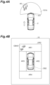
- FIG. 4A is an example of a surrounding environment of a vehicle
- FIG. 4B is an example of a bird's-eye view video corresponding to the surrounding environment shown in FIG. 4A
- the vehicle 2 is moving forward and a moving object 40, which is a pedestrian, is present ahead of the vehicle 2.
- the vehicle 2 determines that the moving object 40 is present in the front range 101A of the front camera 101 based on the detection result of the front camera 101 and/or the external sensor 12.
- the control unit 14 selects the real-time video as the synthesis target video.
- the control unit 14 outputs a first bird's-eye view video GR2 obtained by synthesizing the real-time video.
- FIG. 4A it is assumed that the vehicle 2 is moving forward and a moving object 40, which is a pedestrian, is present ahead of the vehicle 2.
- the vehicle 2 determines that the moving object 40 is present in the front range 101A of the front camera 101 based on the detection result of the front camera 101 and/or the external sensor 12.
- the display unit 15 displays the first bird's-eye view video GR2 output by the control unit 14.
- the first bird's-eye view video GR2 includes a moving object image OB40 corresponding to the moving object 40.
- FIG. 5A illustrates an example of a surrounding environment of a vehicle
- FIG. 5B illustrates an example of a bird's-eye view video corresponding to the surrounding environment illustrated in FIG. 5A
- FIG. 5A it is assumed that the vehicle 2 is moving forward and a stationary object 30 such as a pole is present ahead of the vehicle 2.
- the vehicle 2 determines that the stationary object 30 is present in the front range 101A of the front camera 101 based on the detection result of the front camera 101 and/or the external sensor 12.
- the control unit 14 selects past video as the video to be synthesized.
- the control unit 14 outputs a second bird's-eye view video GR3 obtained by synthesizing the past video.
- FIG. 5A it is assumed that the vehicle 2 is moving forward and a stationary object 30 such as a pole is present ahead of the vehicle 2.
- the vehicle 2 determines that the stationary object 30 is present in the front range 101A of the front camera 101 based on the detection result of the front camera 101 and/or the external sensor 12.
- the display unit 15 displays the second bird's-eye view video GR3 output by the control unit 14.
- the second bird's-eye view video GR3 includes a stationary object image OB30 corresponding to the stationary object 30.
- OB30 corresponding to the stationary object 30.
- FIG. 6 is a flowchart showing the operation of the video display device.
- the flowchart illustrated in FIG. 6 is executed by the control unit 14, for example, at a timing when a driver operation is received.
- the control unit 14 determines whether or not obstacle presents in the camera video at step S 10.
- the control unit 14 determines the presence or absence of obstacle in the vicinity of the vehicle 2 based on the detection results of the plurality of cameras 10 and/or the external sensor 12.
- step S10 When it is determined that the obstacle presents in the camera video (step S10: YES), the control unit 14 determines whether or not the obstacle is a moving object in step S12. The control unit 14 determines whether the obstacle determined in step S10 is a moving object based on the detection results of the plurality of cameras 10 and/or the external sensor 12.
- step S10 When it is determined that the obstacle does not present in the camera video (step S10: NO) or when it is determined that the obstacle is not a moving object (step S12: NO), the control unit 14 selects the past video as the video serving as the synthesis target in step S16. Then, the control unit 14 displays the second bird's-eye view video on the display unit 15 (see FIG. 5B ).
- step S14 or step S16 has ended, the flowchart ends. The flowchart is repeatedly executed until a driver operation for termination is received.
- an image to be synthesized is selected from the real-time video and the past video based on the situation around the vehicle 2, and the bird's-eye view video in which the selected image is synthesized is output.
- the video display device 1 can display the bird's-eye view video in which the disappearance or duplication of objects is sufficiently suppressed compared to a case where the real-time video is always reflected in the composition of the bird's-eye view video, and can display the bird's-eye view video corresponding to changes in the surrounding environment compared to a case where the past video is always reflected in the composition of the bird's-eye view video.
- the video display device 1 can properly display the bird's-eye view video of the vehicle 2.
- FIG. 7 is a block diagram illustrating an example of a configuration of a vehicle including a video display device according to the modified example.
- a video display device 1A shown in FIG. 7 is different from the video display device 1 in that it does not include the plurality of cameras 10 and includes only the rear camera 104, and in that a part of the operation of a control unit 14A is different from that of the control unit 14, and the others are the same.
- differences will be mainly described, and redundant description will not be repeated.
- the control unit 14A first generates bird's-eye view video using only the real-time video of the rear camera 104.
- the control unit 14A obtains the past video due to the movement of the vehicle 2
- the control unit 14A synthesizes the real-time video and the past video stored in the storage unit 11 to generate bird's-eye view video.
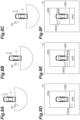
- FIGS. 8A, 8B, and 8C are examples of the surrounding environment of the vehicle
- FIGS. 8D, 8E, and 8F are examples of the bird's-eye view video corresponding to the surrounding environment shown in FIGS. 8A, 8B, and 8C .
- the control unit 14A generates a synthesized first bird's-eye view video GR4 using only real-time video, as shown in FIG. 8D , when the vehicle 2 is in the position of FIG. 8A .
- the video is displayed only on an area AR5 corresponding to the imaging range of the rear camera 104, and the other area is, for example, blank.
- the stationary object image OB30 corresponding to the stationary object 30 is displayed on the area AR5.
- the control unit 14A when the vehicle 2 is in the position of FIG. 8B , the control unit 14A generates a second bird's-eye view video GR5 in which the real-time video and the past video are synthesized, as shown in FIG. 8E .
- the second bird's-eye view video GR5 video is displayed only in the area AR5 corresponding to the imaging range of the rear camera 104 and an area AR6 corresponding to past images, and the other areas are, for example, blank.
- the control unit 14A when the vehicle 2 is at the position of FIG. 8C , the control unit 14A generates a second bird's-eye view video GR6 in which the real-time video and the past video are synthesized, as shown in FIG. 8F .
- the second bird's-eye view video GR6 video is displayed only in the area AR5 corresponding to the imaging range of the rear camera 104 and the area AR6 corresponding to past image, and the other area is, for example, blank. Since the second bird's-eye view video GR6 has more past video available than the second bird's-eye view video GR5, the area AR6 is longer.
- the control unit 14A displays the first bird's-eye view video (for example, FIG. 8D ) when a moving object is detected, and displays the second bird's-eye view video (for example, FIGS. 8E and 8F ) when a moving object is not detected.
- the video display device 1A increases the displayable range by displaying the past video when a moving object is not detected, thereby increasing the amount of information to be reported, and when a moving object is detected, accurate information can be provided to the driver by not displaying the past video that cannot respond to the intrusion of the moving object.
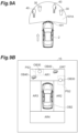
- FIG. 9A is an example of a surrounding environment of a vehicle
- FIG. 9B is an example of a bird's-eye view video corresponding to the surrounding environment shown in FIG. 9A
- the vehicle 2 is moving forward, and the stationary object 30 such as a pole and the moving object 40 which is a pedestrian present ahead of the vehicle 2.
- the vehicle 2 determines that the stationary object 30 and the moving object 40 are present in the front range 101A of the front camera 101 based on the detection result of the front camera 101 and/or the external sensor 12.
- the control unit 14 selects real-time video and past video as the video to be synthesized.
- the control unit 14 generates the first bird's-eye view video obtained by synthesizing the real-time video, and synthesizes the bird's-eye view video regarding the stationary object 30 based on the past video with respect to the first bird's-eye view video.
- the control unit 14 determines whether there is any past video of the stationary object 30 based on the position of the stationary object 30.
- the control unit 14 may determine whether the past video of the stationary object 30 presents by matching the past video with the real-time video.
- the control unit 14 generates a bird's-eye view video of the stationary object 30.
- the control unit 14 may cut the video region of the certain range in which the stationary object 30 appears and generate the bird's-eye view video from the cut video region, or may generate the entire bird's-eye view video from the past video and then cut the video region of the certain range in which the stationary object 30 appears.
- the generated bird's-eye view video regarding the stationary object 30 is overwritten to overlap the image of the stationary object 30 on the first bird's-eye view video generated from the real-time video.
- a second bird's-eye view video GR7 shown in FIG. 9B is generated.
- Areas PS2 and PS3 including the stationary object image OB30 are regions generated based on the past video.
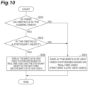
- FIG. 10 is a flowchart illustrating an operation of the video display device according to the modified example.
- the flowchart illustrated in FIG. 10 is executed by the control unit 14, for example, at a timing when a driver operation is received.
- step S20 When it is determined that an obstacle presents in the camera video (step S20: YES), the control unit 14 determines whether or not the obstacle is a stationary object in step S22. The control unit 14 determines whether the object determined in step S20 is a stationary object based on the detection results of the plurality of cameras 10 and/or the external sensor 12.
- control unit 14 selects the real-time video as the video serving as the synthesis target in step S24.
- the control unit 14 then causes the display unit 15 to display the first bird's-eye view video.
- step S22 When it is determined that the object is a stationary object (step S22: YES), the control unit 14 selects the real-time video and the past video as videos to be synthesized in step S26. Then, the control unit 14 generates the stationary object image OB30 based on the past video while creating the first bird's-eye view video based on the real-time video. The control unit 14 displays, in the display unit 15, the second bird's-eye view video GR7 in which the stationary object image OB30 is synthesized with first bird's-eye view video (see FIG. 9B ).
- step S24 or step S26 is completed, the flowchart ends. The flowchart is repeatedly executed until a driver operation for termination is received.
- the video display device can suppress disappearance or duplication of a stationary object while appropriately displaying a moving object in real-time.
- the video display device may use the presence or absence of a moving object as an additional condition for generating the second bird's-eye view video. That is, the video display device may be configured to generate the second bird's-eye view video when both the moving object and the stationary object are present within the imaging range of the plurality of cameras 10.
- the second bird's-eye view video based on only the past video may be displayed.
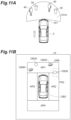
- FIG. 11A is an example of a surrounding environment of a vehicle
- FIG. 11B is an example of a bird's-eye view video corresponding to the surrounding environment shown in FIG. 11A
- the vehicle 2 is moving forward, and the stationary object 30 such as a pole and the moving object 40 which is a pedestrian present ahead of the vehicle 2.
- the vehicle 2 determines that the stationary object 30 and the moving object 40 are present in the front range 101A of the front camera 101 based on the detection result of the front camera 101 and/or the external sensor 12.
- the control unit 14 selects real-time video and past video as the video to be synthesized.
- the control unit 14 generates the first bird's-eye view video obtained by synthesizing the real-time video, and synthesizes the bird's-eye view video of the stationary object 30 based on the past video with respect to the first bird's-eye view video.
- the control unit 14 determines whether there is any past video of the stationary object 30 based on the position of the stationary object 30.
- the control unit 14 may determine whether the past video of the stationary object 30 presents by matching the past video with the real-time video.
- the control unit 14 determines whether or not the display position of the stationary object 30 overlaps the synthesis boundary of the bird's-eye view video.
- the synthesis boundary is a boundary between the front area AR1, the right-side area AR2, the left-side area AR3, and the rear area AR4.
- the control unit 14 generates the bird's-eye view video of the stationary object 30.
- the control unit 14 may cut the video region within a certain range in which the stationary object 30 appears and generate the bird's-eye view video from the cut video region, or may generate the entire bird's-eye view video from the past video and then cut the video region within a certain range in which the stationary object 30 appears.
- the generated bird's-eye view video regarding the stationary object 30 is overwritten to overlap the image of the stationary object 30 on the first bird's-eye view video generated from the real-time video.
- a second bird's-eye view video GR8 illustrated in FIG. 11B is generated.
- An area PS5 including the stationary object image OB30 overlapping with the synthesis boundary is a region generated based on the past video.
- FIG. 12 is a flowchart illustrating an operation of the video display device according to the modified example.
- the flowchart illustrated in FIG. 12 is executed by the control unit 14 at a timing when, for example, a driver operation is received.
- step S32 When it is determined that the obstacle is a stationary object (step S32: YES), the control unit 14 determines whether or not the obstacle overlaps the synthesis boundary in step S33.
- the control unit 14 calculates the display position of the stationary object from the imaging results of the plurality of cameras 10, and determines whether or not the display position overlaps the synthesis boundary.
- step S33 When it is determined that the obstacle overlaps with the synthesis boundary (step S33: YES), the control unit 14 selects the real-time video and the past video as the video serving as the synthesis target in step S36. Then, the control unit 14 generates the stationary object image OB30 overlapping with the synthesis boundary based on the past video while creating the first bird's-eye view video based on the real-time video. The control unit 14 displays, in the display unit 15, the second bird's-eye view video GR8 in which the stationary object image OB30 is synthesized with the first bird's-eye view video (see FIG. 11B ).
- step S34 or step S36 has ended, the flowchart ends. The flowchart is repeatedly executed until a driver operation for termination is received.
- the video display device can suppress disappearance or duplication of a stationary object while appropriately displaying a moving object in real-time.
- the video display device may use the presence or absence of a moving object as an additional condition for generating the second bird's-eye view video. That is, the video display device may be configured to generate the second bird's-eye view video when both the moving object and the stationary object are present within the imaging range of the plurality of cameras 10.
- the second bird's-eye view video based on only the past video may be displayed.
- the control unit 14 may select an image to be synthesized based on the traveling state of the vehicle, and output a bird's-eye view video obtained by synthesizing the selected image.
- the control unit 14 differentiates the traveling state of the vehicle 2 into two states: “stopped state” and “moving state". "Moving state” includes “forward state”, “reverse state”, “right-turning state”, and "left-turning state”.
- the control unit 14 When the traveling state of the vehicle 2 is "moving state", the control unit 14 generates an area ahead of the travel direction of the vehicle 2 in the second bird's-eye view video based on the real-time video showing ahead of travel direction of the vehicle 2, and generates an area behind the travel direction of the vehicle 2 in the second bird's-eye view video based on the past video showing behind the travel direction of the vehicle 2. That is, the control unit 14 sets the bird's-eye view video based on the real-time video for the area to be traveled, and sets the bird's-eye view video based on the past video for the area already traveled.
- FIGS. 13A and 13B are examples of a surrounding environment of a vehicle
- FIG. 13C is an example of a bird's-eye view video corresponding to the surrounding environment shown in FIG. 13B .
- the control unit 14 generates the front area AR1 of the second bird's-eye view video GR9 (an area ahead of the travel direction in the vehicle 2) based on the real-time video that captures the forward direction of the vehicle 2.
- control unit 14 generates the rear area AR4 (an area behind the travel direction in the vehicle 2) of the second bird's-eye view video based on the past video that captures the backward direction of the vehicle 2.
- the rear area AR4 becomes an area PS6 based on past video.
- FIG. 14 is a flowchart illustrating an operation of the video display device according to the modified example.
- the flowchart illustrated in FIG. 14 is executed by the control unit 14, for example, at the timing when a driver operation is received.
- step S40 the control unit 14 determines whether the traveling state of the vehicle 2 is a stopped state.
- the control unit 14 determines the traveling state of the vehicle 2 based on the movements of the plurality of cameras 10 or the detection results of the internal sensor 13.
- step S40 When it is determined that the vehicle 2 is in a stopped state (step S40: YES), the control unit 14 displays the first bird's-eye view video synthesized with the real-time video.
- the control unit 14 may display a second bird's-eye view video in which only the past video is synthesized.
- step S40 determines whether or not the traveling state of the vehicle 2 is a forward state in step S44.
- step S44 selects real-time video and past video as videos to be synthesized in step S46.
- the control unit 14 generates the bird's-eye view video based on the past video behind the vehicle while creating the first bird's-eye view video based on the real-time video.
- the control unit 14 causes the display unit 15 to display the second bird's-eye view video GR9 obtained by synthesizing the bird's-eye view video behind the vehicle with the first bird's-eye view video (see FIG. 13C ).
- step S48 determines whether or not the traveling state of the vehicle 2 is a right-turning state in step S52.
- the control unit 14 selects real-time video and past video as videos to be synthesized in step S54. Then, the control unit 14 generates the first bird's-eye view video based on the real-time video, and generates the bird's-eye view video based on the past video of the vehicle left-side based on the past video.
- the control unit 14 causes the display unit 15 to display the second bird's-eye view video GR9 obtained by synthesizing the bird's-eye view video of the vehicle left-side with the first bird's-eye view video.
- the traveling state of the vehicle 2 is a left-turning state.
- the control unit 14 selects real-time video and past video as videos to be synthesis targets in step S56. Then, the control unit 14 creates the first bird's-eye view video based on the real-time video, and generates the bird's-eye view video based on the past video of the vehicle right side based on the past video.
- the control unit 14 causes the display unit 15 to display the second bird's-eye view video GR9 obtained by synthesizing the bird's-eye view video of the vehicle right side with the first bird's-eye view video.
- step S42, step S46, step S50, step S54, or step S56 the flowchart ends.
- the flowchart is repeatedly executed until a driver operation for termination is received.
- the video display device can respond to an environmental change by displaying the travel direction to which the most attention should be paid using real-time video, and can suppress the disappearance or duplication of an object by displaying behind the travel direction, which has lower importance than the travel direction, using past video.
- a video display device comprising:
- control unit outputs the first bird's-eye view video when a moving object presents within an imaging range of the camera, and outputs the second bird's-eye view video obtained by synthesizing the past video when the moving object does not present within the imaging range of the camera.
- the video display device further comprising a plurality of cameras including the camera, wherein the storage unit stores the past video captured by the plurality of cameras, and the control unit generates the first bird's-eye view video by synthesizing the real-time video captured by the plurality of cameras, and generates the second bird's-eye view video by synthesizing the past video, or by synthesizing the past video and the real-time video.
- control unit outputs the second bird's-eye view video, the second bird's-eye view video obtained by synthesizing the bird's-eye view video of a stationary object based on the past video with the first bird's-eye view video, in a case where the stationary object presents within an imaging range of the plurality of cameras.
- control unit outputs the second bird's-eye view video, the second bird's-eye view video obtained by synthesizing the bird's-eye view video of a stationary object based on the past video with the first bird's-eye view video, in a case where the stationary object presents within an imaging range of the plurality of cameras and a display position of the stationary object overlaps with a synthesis boundary of the bird's-eye view video.
Landscapes
- Engineering & Computer Science (AREA)
- Multimedia (AREA)
- Mechanical Engineering (AREA)
- Signal Processing (AREA)
- Chemical & Material Sciences (AREA)
- Combustion & Propulsion (AREA)
- Transportation (AREA)
- Closed-Circuit Television Systems (AREA)
- Image Processing (AREA)
Abstract
A video display device includes: a camera configured to capture video of surroundings of a vehicle; a storage unit configured to store the video captured by the camera as past video; a control unit configured to select video to be synthesized from real-time video captured by the camera and the past video stored in the storage unit based on a situation around the vehicle or a traveling state of the vehicle, and output bird's-eye view video looking down at the vehicle from a viewpoint above the vehicle, the bird's-eye view video being obtained by synthesizing the video selected; and a display unit configured to display the bird's-eye view video output by the control unit.
Description
- This application is based on
Japanese Patent Application No. 2023-183388 filed with Japan Patent Office on October 25, 2023 - The present disclosure relates to a video display device.
-
Japanese Patent Application Laid-Open No. 2007-104373 - The apparatus described in
Japanese Patent Application Laid-Open No. 2007-104373 - According to an aspect of the present disclosure, there is provided a video display device including: a camera configured to capture video of surroundings of a vehicle; a storage unit configured to store the video captured by the camera as past video; a control unit configured to select video to be synthesized from real-time video captured by the camera and the past video stored in the storage unit based on a situation around the vehicle or a traveling state of the vehicle, and output bird's-eye view video looking down at the vehicle from a viewpoint above the vehicle, the bird's-eye view video being obtained by synthesizing the video selected; and a display unit configured to display the bird's-eye view video output by the control unit.
- In the video display device, video to be synthesized is selected from the real-time video and the past video in accordance with the situation around the vehicle or the traveling state of the vehicle, and the bird's-eye view video in which the selected video is synthesized is output. The video display device reflects the past video in the composition of the bird's-eye view video in accordance with the situation around the vehicle or the traveling state of the vehicle, thereby making it possible to display the bird's-eye view video in which disappearance or duplication of an object is sufficiently suppressed as compared with the case where the real-time video is always reflected in the composition of the bird's-eye view video, and to display the bird's-eye view video corresponding to a change in the surrounding environment as compared with the case where the past video is always reflected in the composition of the bird's-eye view video. Therefore, the video display device can appropriately display the bird's-eye view video of the vehicle.
- In one embodiment, the control unit may output any one of first bird's-eye view video obtained by synthesizing the real-time video and second bird's-eye view video obtained by synthesizing at least the past video based on the situation around the vehicle, or may output the second bird's-eye view video based on the traveling state of the vehicle. The video display device may display a first bird's-eye view video or a second bird's-eye view video based on the situation around the vehicle or the traveling state of the vehicle.
- In one embodiment, the control unit may output the first bird's-eye view video when a moving object presents within the imaging range of the camera, and may output the second bird's-eye view video obtained by synthesizing the past video when the moving object does not present within the imaging range of the camera. In this case, the video display device may output the first bird's-eye view video that prioritizes coping with changes in the surrounding environment when a moving object is present, and may output the second bird's-eye view video that prioritizes resolving object loss or resolving object duplication when a moving object is not present.
- In one embodiment, the video display device may include a plurality of cameras including the camera, and the storage unit may store past video captured by the plurality of cameras, and the control unit may generate the first bird's-eye view video by synthesizing real-time video captured by the plurality of cameras, and may generate the second bird's-eye view video by synthesizing past video or synthesizing past video and real-time video. In this case, the video display device may display the bird's-eye view video with high accuracy by synthesizing the images of the plurality of cameras.
- In one embodiment, the control unit may output the second bird's-eye view video, which is obtained by synthesizing the bird's-eye view video of the stationary object based on the past video with the first bird's-eye view video, in a case where the stationary object presents within the imaging ranges of the plurality of cameras. In this case, the video display device can suppress disappearance or duplication of the stationary object while appropriately displaying the moving object in real-time.
- In one embodiment, the control unit may output the second bird's-eye view video, which is obtained by synthesizing the bird's-eye view video of the stationary object based on the past video with the first bird's-eye view video, in a case where the stationary object presents within the imaging range of the plurality of cameras and a display position of the stationary object overlaps with the synthesis boundary of the bird's-eye view video. In this case, the video display device can suppress disappearance or duplication of the stationary object while appropriately displaying the surrounding environment in real-time.
- In one embodiment, when the traveling state of the vehicle is moving state, the control unit may generate an area ahead of the travel direction of the vehicle in the second bird's-eye view video based on the real-time video representing ahead of the travel direction of the vehicle, and may generate an area behind the travel direction of the vehicle in the second bird's-eye view video based on the past video representing behind the travel direction of the vehicle. In this case, the video display device can respond to an environmental change by displaying the travel direction to which the most attention should be paid using real-time video, and can suppress the disappearance or duplication of an object by displaying the rearward direction, which is of lower importance compared to the travel direction, using past video.
- According to the present disclosure, there is provided a technique capable of appropriately displaying a bird's-eye view video of a vehicle.
-
-
FIG. 1 is a block diagram illustrating an example of a configuration of a vehicle including a video display device according to an embodiment. -
FIG. 2 illustrates an example of imaging regions of a plurality of sensors provided in avehicle 2. -
FIG. 3 shows an example of a bird's-eye view video displayed on the display unit. -
FIG. 4A is an example of a surrounding environment of a vehicle. -
FIG. 4B is an example of a bird's-eye view video corresponding to the surrounding environment shown inFIG. 4A . -
FIG. 5A illustrates an example of a surrounding environment of a vehicle. -
FIG. 5B illustrates an example of a bird's-eye view video corresponding to the surrounding environment illustrated inFIG. 5A . -
FIG. 6 is a flowchart showing the operation of the video display device. -
FIG. 7 is a block diagram illustrating an example of a configuration of a vehicle including a video display device according to the modified example. -
FIGS. 8A, 8B, and 8C are examples of the surrounding environment of the vehicle. -
FIGS. 8D, 8E, and 8F are examples of the bird's-eye view video corresponding to the surrounding environment shown inFIGS. 8A, 8B, and 8C . -
FIG. 9A is an example of a surrounding environment of a vehicle. -
FIG. 9B is an example of a bird's-eye view video corresponding to the surrounding environment shown inFIG. 9A . -
FIG. 10 is a flowchart illustrating an operation of the video display device according to the modified example. -
FIG. 11A is an example of a surrounding environment of a vehicle. -
FIG. 11B is an example of a bird's-eye view video corresponding to the surrounding environment shown inFIG. 11A . -
FIG. 12 is a flowchart illustrating an operation of the video display device according to the modified example. -
FIGS. 13A and 13B are examples of a surrounding environment of a vehicle. -
FIG. 13C is an example of a bird's-eye view video corresponding to the surrounding environment shown inFIG. 13B . -
FIG. 14 is a flowchart illustrating an operation of the video display device according to the modified example. - Hereinafter, embodiments of the present disclosure will be described with reference to drawings.
-
FIG. 1 is a block diagram illustrating an example of a configuration of a vehicle including a video display device according to an embodiment. As shown inFIG. 1 , avideo display device 1 is mounted on avehicle 2 as an example. Thevehicle 2 may be a vehicle driven by a driver, or may be an autonomous driving vehicle. - The
vehicle 2 includes a plurality ofcameras 10, astorage unit 11, anexternal sensor 12, aninternal sensor 13, acontrol unit 14 and adisplay unit 15. Thevideo display device 1 includes the plurality ofcameras 10, thestorage unit 11, thecontrol unit 14, and thedisplay unit 15. - The plurality of
cameras 10 is a camera group that images the periphery of thevehicle 2. Examples of the plurality ofcameras 10 include afront camera 101, a right-side camera 102, a left-side camera 103, and arear camera 104.FIG. 2 illustrates an example of imaging regions of a plurality of sensors provided in thevehicle 2. As shown inFIG. 2 , thefront camera 101 is provided on a front bumper or the like, and images afront range 101A of thevehicle 2. The right-side camera 102 is provided on a door mirror or the like and captures an image of a right-side range 102A of thevehicle 2. The left-side camera 103 is provided on a door mirror or the like and captures an image of a left-side range 103A of thevehicle 2. Therear camera 104 is provided on a rear bumper or the like, and images arear range 104A of thevehicle 2. - The
storage unit 11 stores, for each camera, the past video captured by the plurality ofcameras 10. The past video means recorded real-time video, and includes moving images and still images. The real-time video is an image captured at a current time by the plurality ofcameras 10, and includes moving images and still images. Thestorage unit 11 is, for example, a storage medium such as a read only memory (ROM), a random-access memory (RAM), or a hard disk drive (HDD). - The
external sensor 12 is a sensor that detects the surrounding environment of thevehicle 2. Theexternal sensor 12 is, for example, a radar sensor. The radar sensor is detection equipment that detects an object around the vehicle using radio waves (for example, millimeter waves) or light. The radar sensor includes, for example, a millimeter wave radar or a light detection and ranging (LiDAR). - The
internal sensor 13 is a sensor that detects the traveling state of thevehicle 2. Theinternal sensor 13 may include, for example, a GPS receiver, a vehicle speed sensor, an acceleration sensor, and a yaw rate sensor. - The
control unit 14 has a function of controlling the video display device. Thecontrol unit 14 includes, for example, an electronic control unit (ECU). The ECU includes a central processing unit (CPU), a read-only memory (ROM), a random-access memory (RAM), and a controller area network (CAN). This is an electronic control unit having a communication circuit and the like. Thecontrol unit 14 generates a bird's-eye view video by synthesizing images captured by the plurality ofcameras 10. The bird's-eye view video is an image of thevehicle 2 viewed from a viewpoint above thevehicle 2, and includes a moving image and a still image. - The
display unit 15 displays the bird's-eye view video output by thecontrol unit 14. Thedisplay unit 15 is, for example, a display device.FIG. 3 shows an example of a bird's-eye view video displayed on the display unit. As shown inFIG. 3 , thedisplay unit 15 displays a bird's-eye view video GR1 produced by thecontrol unit 14. Thecontrol unit 14 produces the bird's-eye view video GR1 with a vehicle object OB2 corresponding to thevehicle 2. Thecontrol unit 14 inputs image signals from the plurality ofcameras 10 and performs image processing to generate bird's-eye view video looking down at thevehicle 2 from a directly upward viewpoint. The viewpoint conversion may be performed based on an arrangement position and an imaging direction of each of the plurality ofcameras 10 based on a reference point O of thevehicle 2. The image processing for the viewpoint conversion may be executed by software or may be executed by hardware circuits. - The
control unit 14 displays a front area AR1 of thevehicle 2 using an image signal captured by thefront camera 101. Thecontrol unit 14 displays a right-side area AR2 of thevehicle 2 using an image signal captured by the right-side camera 102. Thecontrol unit 14 displays a left-side area AR3 of thevehicle 2 using an image signal captured by the left-side camera 103. Thecontrol unit 14 displays a rear area AR4 of thevehicle 2 using an image signal captured by therear camera 104. Thus, the bird's-eye view video GR1 is generated. - The
control unit 14 selects an image to be synthesized from real-time video captured by the plurality ofcameras 10 and past video stored in thestorage unit 11. The video to be synthesized is selected based on the situation around thevehicle 2. For example, thecontrol unit 14 determines whether there is a moving object in imaging ranges of the plurality ofcameras 10 based on detection results of the plurality ofcameras 10 and/or theexternal sensor 12. In the case of using a result of imaging by the plurality ofcameras 10, thecontrol unit 14 detects a moving object based on a motion vector between frames. When thecontrol unit 14 uses theexternal sensor 12 detection result, the moving object is detected based on the temporal displacement of the distance to the detected object. - The
control unit 14 selects real-time video as the synthesis target video when there are moving objects within the imaging range of the plurality ofcameras 10. Accordingly, thecontrol unit 14 outputs a bird's-eye view video (first bird's-eye view video) obtained by synthesizing the real-time video. The first bird's-eye view video is the bird's-eye view video composed of video at the current time captured by the plurality ofcameras 10. When a moving object does not present in the imaging ranges of the plurality ofcameras 10, thecontrol unit 14 selects the past video as an image serving as a synthesis target. As a result, thecontrol unit 14 outputs the bird's-eye view video (second bird's-eye view video) obtained by synthesizing the past video stored in thestorage unit 11. As described above, for example, thecontrol unit 14 outputs any one of the first bird's-eye view video obtained by synthesizing the real-time video and the second bird's-eye view video obtained by synthesizing the past video in accordance with the situation around thevehicle 2. -
FIG. 4A is an example of a surrounding environment of a vehicle, andFIG. 4B is an example of a bird's-eye view video corresponding to the surrounding environment shown inFIG. 4A . As shown inFIG. 4A , it is assumed that thevehicle 2 is moving forward and a movingobject 40, which is a pedestrian, is present ahead of thevehicle 2. Thevehicle 2 determines that the movingobject 40 is present in thefront range 101A of thefront camera 101 based on the detection result of thefront camera 101 and/or theexternal sensor 12. In this case, thecontrol unit 14 selects the real-time video as the synthesis target video. Thecontrol unit 14 outputs a first bird's-eye view video GR2 obtained by synthesizing the real-time video. As shown inFIG. 4B , thedisplay unit 15 displays the first bird's-eye view video GR2 output by thecontrol unit 14. The first bird's-eye view video GR2 includes a moving object image OB40 corresponding to the movingobject 40. Thus, the driver can grasp the periphery of thevehicle 2 in real-time. -
FIG. 5A illustrates an example of a surrounding environment of a vehicle, andFIG. 5B illustrates an example of a bird's-eye view video corresponding to the surrounding environment illustrated inFIG. 5A . As shown inFIG. 5A , it is assumed that thevehicle 2 is moving forward and astationary object 30 such as a pole is present ahead of thevehicle 2. Thevehicle 2 determines that thestationary object 30 is present in thefront range 101A of thefront camera 101 based on the detection result of thefront camera 101 and/or theexternal sensor 12. In this case, thecontrol unit 14 selects past video as the video to be synthesized. Thecontrol unit 14 outputs a second bird's-eye view video GR3 obtained by synthesizing the past video. As shown inFIG. 5B , thedisplay unit 15 displays the second bird's-eye view video GR3 output by thecontrol unit 14. The second bird's-eye view video GR3 includes a stationary object image OB30 corresponding to thestationary object 30. In the second bird's-eye view video GR3, since allareas PS 1 of the video are created based on the past video, there are no boundaries due to compositing, and object loss or duplication is avoided. -
FIG. 6 is a flowchart showing the operation of the video display device. The flowchart illustrated inFIG. 6 is executed by thecontrol unit 14, for example, at a timing when a driver operation is received. - As illustrated in
FIG. 6 , thecontrol unit 14 determines whether or not obstacle presents in the camera video atstep S 10. Thecontrol unit 14 determines the presence or absence of obstacle in the vicinity of thevehicle 2 based on the detection results of the plurality ofcameras 10 and/or theexternal sensor 12. - When it is determined that the obstacle presents in the camera video (step S10: YES), the
control unit 14 determines whether or not the obstacle is a moving object in step S12. Thecontrol unit 14 determines whether the obstacle determined in step S10 is a moving object based on the detection results of the plurality ofcameras 10 and/or theexternal sensor 12. - When it is determined that the object is a moving object (step S12: YES), the
control unit 14 selects the real-time video as the video serving as the synthesis target in step S14. Then, thecontrol unit 14 displays the first bird's-eye view video on the display unit 15 (seeFIG. 4B ). - When it is determined that the obstacle does not present in the camera video (step S10: NO) or when it is determined that the obstacle is not a moving object (step S12: NO), the
control unit 14 selects the past video as the video serving as the synthesis target in step S16. Then, thecontrol unit 14 displays the second bird's-eye view video on the display unit 15 (seeFIG. 5B ). When step S14 or step S16 has ended, the flowchart ends. The flowchart is repeatedly executed until a driver operation for termination is received. - In the
video display device 1, an image to be synthesized is selected from the real-time video and the past video based on the situation around thevehicle 2, and the bird's-eye view video in which the selected image is synthesized is output. By reflecting the past video in the composition of the bird's-eye view video in accordance with the situation around thevehicle 2, thevideo display device 1 can display the bird's-eye view video in which the disappearance or duplication of objects is sufficiently suppressed compared to a case where the real-time video is always reflected in the composition of the bird's-eye view video, and can display the bird's-eye view video corresponding to changes in the surrounding environment compared to a case where the past video is always reflected in the composition of the bird's-eye view video. Thus, thevideo display device 1 can properly display the bird's-eye view video of thevehicle 2. - Although the exemplary embodiments have been described above, various omissions, substitutions, and changes may be made without being limited to the above-described exemplary embodiments.
-
FIG. 7 is a block diagram illustrating an example of a configuration of a vehicle including a video display device according to the modified example. Avideo display device 1A shown inFIG. 7 is different from thevideo display device 1 in that it does not include the plurality ofcameras 10 and includes only therear camera 104, and in that a part of the operation of acontrol unit 14A is different from that of thecontrol unit 14, and the others are the same. Hereinafter, differences will be mainly described, and redundant description will not be repeated. - The
control unit 14A first generates bird's-eye view video using only the real-time video of therear camera 104. When thecontrol unit 14A obtains the past video due to the movement of thevehicle 2, thecontrol unit 14A synthesizes the real-time video and the past video stored in thestorage unit 11 to generate bird's-eye view video. -
FIGS. 8A, 8B, and 8C are examples of the surrounding environment of the vehicle, andFIGS. 8D, 8E, and 8F are examples of the bird's-eye view video corresponding to the surrounding environment shown inFIGS. 8A, 8B, and 8C . As shown in the order ofFIGS. 8A, 8B, and 8C , it is assumed that thevehicle 2 moves so as to move backward. Thecontrol unit 14A generates a synthesized first bird's-eye view video GR4 using only real-time video, as shown inFIG. 8D , when thevehicle 2 is in the position ofFIG. 8A . In the first bird's-eye view video GR4, the video is displayed only on an area AR5 corresponding to the imaging range of therear camera 104, and the other area is, for example, blank. The stationary object image OB30 corresponding to thestationary object 30 is displayed on the area AR5. - Subsequently, when the
vehicle 2 is in the position ofFIG. 8B , thecontrol unit 14A generates a second bird's-eye view video GR5 in which the real-time video and the past video are synthesized, as shown inFIG. 8E . In the second bird's-eye view video GR5, video is displayed only in the area AR5 corresponding to the imaging range of therear camera 104 and an area AR6 corresponding to past images, and the other areas are, for example, blank. Subsequently, when thevehicle 2 is at the position ofFIG. 8C , thecontrol unit 14A generates a second bird's-eye view video GR6 in which the real-time video and the past video are synthesized, as shown inFIG. 8F . In the second bird's-eye view video GR6, video is displayed only in the area AR5 corresponding to the imaging range of therear camera 104 and the area AR6 corresponding to past image, and the other area is, for example, blank. Since the second bird's-eye view video GR6 has more past video available than the second bird's-eye view video GR5, the area AR6 is longer. - Similarly to the
control unit 14, thecontrol unit 14A displays the first bird's-eye view video (for example,FIG. 8D ) when a moving object is detected, and displays the second bird's-eye view video (for example,FIGS. 8E and 8F ) when a moving object is not detected. As a result, thevideo display device 1A increases the displayable range by displaying the past video when a moving object is not detected, thereby increasing the amount of information to be reported, and when a moving object is detected, accurate information can be provided to the driver by not displaying the past video that cannot respond to the intrusion of the moving object. -
FIG. 9A is an example of a surrounding environment of a vehicle, andFIG. 9B is an example of a bird's-eye view video corresponding to the surrounding environment shown inFIG. 9A . As shown inFIG. 9A , it is assumed that thevehicle 2 is moving forward, and thestationary object 30 such as a pole and the movingobject 40 which is a pedestrian present ahead of thevehicle 2. Thevehicle 2 determines that thestationary object 30 and the movingobject 40 are present in thefront range 101A of thefront camera 101 based on the detection result of thefront camera 101 and/or theexternal sensor 12. In this case, thecontrol unit 14 selects real-time video and past video as the video to be synthesized. Thecontrol unit 14 generates the first bird's-eye view video obtained by synthesizing the real-time video, and synthesizes the bird's-eye view video regarding thestationary object 30 based on the past video with respect to the first bird's-eye view video. - First, the
control unit 14 determines whether there is any past video of thestationary object 30 based on the position of thestationary object 30. Thecontrol unit 14 may determine whether the past video of thestationary object 30 presents by matching the past video with the real-time video. When it is determined that there is a past video of thestationary object 30, thecontrol unit 14 generates a bird's-eye view video of thestationary object 30. Thecontrol unit 14 may cut the video region of the certain range in which thestationary object 30 appears and generate the bird's-eye view video from the cut video region, or may generate the entire bird's-eye view video from the past video and then cut the video region of the certain range in which thestationary object 30 appears. The generated bird's-eye view video regarding thestationary object 30 is overwritten to overlap the image of thestationary object 30 on the first bird's-eye view video generated from the real-time video. As a result, a second bird's-eye view video GR7 shown inFIG. 9B is generated. Areas PS2 and PS3 including the stationary object image OB30 are regions generated based on the past video. -
FIG. 10 is a flowchart illustrating an operation of the video display device according to the modified example. The flowchart illustrated inFIG. 10 is executed by thecontrol unit 14, for example, at a timing when a driver operation is received. - As illustrated in
FIG. 10 , thecontrol unit 14 determines whether or not obstacle is present in camera video in step S20. This determination is the same asstep S 10. - When it is determined that an obstacle presents in the camera video (step S20: YES), the
control unit 14 determines whether or not the obstacle is a stationary object in step S22. Thecontrol unit 14 determines whether the object determined in step S20 is a stationary object based on the detection results of the plurality ofcameras 10 and/or theexternal sensor 12. - When it is determined that the obstacle does not present in the camera video (step S20: NO) or when it is determined that the obstacle is not the stationary object (step S22: NO), the
control unit 14 selects the real-time video as the video serving as the synthesis target in step S24. Thecontrol unit 14 then causes thedisplay unit 15 to display the first bird's-eye view video. - When it is determined that the object is a stationary object (step S22: YES), the
control unit 14 selects the real-time video and the past video as videos to be synthesized in step S26. Then, thecontrol unit 14 generates the stationary object image OB30 based on the past video while creating the first bird's-eye view video based on the real-time video. Thecontrol unit 14 displays, in thedisplay unit 15, the second bird's-eye view video GR7 in which the stationary object image OB30 is synthesized with first bird's-eye view video (seeFIG. 9B ). When step S24 or step S26 is completed, the flowchart ends. The flowchart is repeatedly executed until a driver operation for termination is received. - As described above, the video display device can suppress disappearance or duplication of a stationary object while appropriately displaying a moving object in real-time. Note that the video display device may use the presence or absence of a moving object as an additional condition for generating the second bird's-eye view video. That is, the video display device may be configured to generate the second bird's-eye view video when both the moving object and the stationary object are present within the imaging range of the plurality of
cameras 10. In addition, when it is determined that the obstacle does not present in the camera video (step S20: NO), the second bird's-eye view video based on only the past video may be displayed. -
FIG. 11A is an example of a surrounding environment of a vehicle, andFIG. 11B is an example of a bird's-eye view video corresponding to the surrounding environment shown inFIG. 11A . As shown inFIG. 11A , it is assumed that thevehicle 2 is moving forward, and thestationary object 30 such as a pole and the movingobject 40 which is a pedestrian present ahead of thevehicle 2. Thevehicle 2 determines that thestationary object 30 and the movingobject 40 are present in thefront range 101A of thefront camera 101 based on the detection result of thefront camera 101 and/or theexternal sensor 12. In this case, thecontrol unit 14 selects real-time video and past video as the video to be synthesized. Thecontrol unit 14 generates the first bird's-eye view video obtained by synthesizing the real-time video, and synthesizes the bird's-eye view video of thestationary object 30 based on the past video with respect to the first bird's-eye view video. - First, the
control unit 14 determines whether there is any past video of thestationary object 30 based on the position of thestationary object 30. Thecontrol unit 14 may determine whether the past video of thestationary object 30 presents by matching the past video with the real-time video. When it is determined that the past video of thestationary object 30 is present, thecontrol unit 14 determines whether or not the display position of thestationary object 30 overlaps the synthesis boundary of the bird's-eye view video. The synthesis boundary is a boundary between the front area AR1, the right-side area AR2, the left-side area AR3, and the rear area AR4. When thestationary object 30 overlaps with the synthesis boundary, thecontrol unit 14 generates the bird's-eye view video of thestationary object 30. Thecontrol unit 14 may cut the video region within a certain range in which thestationary object 30 appears and generate the bird's-eye view video from the cut video region, or may generate the entire bird's-eye view video from the past video and then cut the video region within a certain range in which thestationary object 30 appears. The generated bird's-eye view video regarding thestationary object 30 is overwritten to overlap the image of thestationary object 30 on the first bird's-eye view video generated from the real-time video. Thus, a second bird's-eye view video GR8 illustrated inFIG. 11B is generated. An area PS5 including the stationary object image OB30 overlapping with the synthesis boundary is a region generated based on the past video. -
FIG. 12 is a flowchart illustrating an operation of the video display device according to the modified example. The flowchart illustrated inFIG. 12 is executed by thecontrol unit 14 at a timing when, for example, a driver operation is received. - As illustrated in
FIG. 12 , thecontrol unit 14 determines whether or not obstacle is present in camera video in step S30. This determination is the same asstep S 10. - When it is determined that the obstacle presents in the camera video (step S30: YES), the
control unit 14 determines whether or not the obstacle is a stationary object in step S32. This determination is the same as step S22. - When it is determined that the obstacle is a stationary object (step S32: YES), the
control unit 14 determines whether or not the obstacle overlaps the synthesis boundary in step S33. Thecontrol unit 14 calculates the display position of the stationary object from the imaging results of the plurality ofcameras 10, and determines whether or not the display position overlaps the synthesis boundary. - When it is determined that the obstacle does not present in the camera video (step S30: NO), when it is determined that the obstacle is not a stationary object (step S32: NO), or when it is determined that the obstacle does not overlap with the synthesis boundary (step S33: NO), the
control unit 14 selects real-time video as a video serving as a synthesis target in step S34. Thecontrol unit 14 then causes thedisplay unit 15 to display the first bird's-eye view video. - When it is determined that the obstacle overlaps with the synthesis boundary (step S33: YES), the
control unit 14 selects the real-time video and the past video as the video serving as the synthesis target in step S36. Then, thecontrol unit 14 generates the stationary object image OB30 overlapping with the synthesis boundary based on the past video while creating the first bird's-eye view video based on the real-time video. Thecontrol unit 14 displays, in thedisplay unit 15, the second bird's-eye view video GR8 in which the stationary object image OB30 is synthesized with the first bird's-eye view video (seeFIG. 11B ). When step S34 or step S36 has ended, the flowchart ends. The flowchart is repeatedly executed until a driver operation for termination is received. - As described above, the video display device can suppress disappearance or duplication of a stationary object while appropriately displaying a moving object in real-time. Note that the video display device may use the presence or absence of a moving object as an additional condition for generating the second bird's-eye view video. That is, the video display device may be configured to generate the second bird's-eye view video when both the moving object and the stationary object are present within the imaging range of the plurality of
cameras 10. In addition, when it is determined that the obstacle does not present in the camera video (step S30: NO), the second bird's-eye view video based on only the past video may be displayed. - The
control unit 14 may select an image to be synthesized based on the traveling state of the vehicle, and output a bird's-eye view video obtained by synthesizing the selected image. Thecontrol unit 14 differentiates the traveling state of thevehicle 2 into two states: "stopped state" and "moving state". "Moving state" includes "forward state", "reverse state", "right-turning state", and "left-turning state". When the traveling state of thevehicle 2 is "moving state", thecontrol unit 14 generates an area ahead of the travel direction of thevehicle 2 in the second bird's-eye view video based on the real-time video showing ahead of travel direction of thevehicle 2, and generates an area behind the travel direction of thevehicle 2 in the second bird's-eye view video based on the past video showing behind the travel direction of thevehicle 2. That is, thecontrol unit 14 sets the bird's-eye view video based on the real-time video for the area to be traveled, and sets the bird's-eye view video based on the past video for the area already traveled. -
FIGS. 13A and 13B are examples of a surrounding environment of a vehicle, andFIG. 13C is an example of a bird's-eye view video corresponding to the surrounding environment shown inFIG. 13B . As shown in the order ofFIGS. 13A and 13B , it is assumed that thevehicle 2 is moving forward. In this case, as illustrated inFIG. 13C , thecontrol unit 14 generates the front area AR1 of the second bird's-eye view video GR9 (an area ahead of the travel direction in the vehicle 2) based on the real-time video that captures the forward direction of thevehicle 2. Then, thecontrol unit 14 generates the rear area AR4 (an area behind the travel direction in the vehicle 2) of the second bird's-eye view video based on the past video that captures the backward direction of thevehicle 2. As a result, only the rear area AR4 becomes an area PS6 based on past video. -
FIG. 14 is a flowchart illustrating an operation of the video display device according to the modified example. The flowchart illustrated inFIG. 14 is executed by thecontrol unit 14, for example, at the timing when a driver operation is received. - As shown in
FIG. 14 , in step S40, thecontrol unit 14 determines whether the traveling state of thevehicle 2 is a stopped state. Thecontrol unit 14 determines the traveling state of thevehicle 2 based on the movements of the plurality ofcameras 10 or the detection results of theinternal sensor 13. - When it is determined that the
vehicle 2 is in a stopped state (step S40: YES), thecontrol unit 14 displays the first bird's-eye view video synthesized with the real-time video. Thecontrol unit 14 may display a second bird's-eye view video in which only the past video is synthesized. - When it is determined that the traveling state of the
vehicle 2 is not a stopped state (step S40: NO), thecontrol unit 14 determines whether or not the traveling state of thevehicle 2 is a forward state in step S44. When it is determined that the traveling state in thevehicle 2 is a forward state (step S44: YES), thecontrol unit 14 selects real-time video and past video as videos to be synthesized in step S46. Then, thecontrol unit 14 generates the bird's-eye view video based on the past video behind the vehicle while creating the first bird's-eye view video based on the real-time video. Thecontrol unit 14 causes thedisplay unit 15 to display the second bird's-eye view video GR9 obtained by synthesizing the bird's-eye view video behind the vehicle with the first bird's-eye view video (seeFIG. 13C ). - When it is determined that the traveling state of the
vehicle 2 is not a forward state (step S44: NO), thecontrol unit 14 determines whether or not the traveling state of thevehicle 2 is a reverse state in step S48. When it is determined that the traveling state of thevehicle 2 is a reverse state (step S48: YES), thecontrol unit 14 selects real-time video and past video as videos to be synthesized in step S50. Then, thecontrol unit 14 generates the first bird's-eye view video based on the real-time video, and generates the bird's-eye view video based on the past video ahead of thevehicle 2. Thecontrol unit 14 causes thedisplay unit 15 to display the second bird's-eye view video GR9 obtained by synthesizing the bird's-eye view video ahead of the vehicle with the first bird's-eye view video. - When it is determined that the traveling state of the
vehicle 2 is not a reverse state (step S48: NO), thecontrol unit 14 determines whether or not the traveling state of thevehicle 2 is a right-turning state in step S52. When it is determined that the traveling state in thevehicle 2 is a right-turning state (step S52: YES), thecontrol unit 14 selects real-time video and past video as videos to be synthesized in step S54. Then, thecontrol unit 14 generates the first bird's-eye view video based on the real-time video, and generates the bird's-eye view video based on the past video of the vehicle left-side based on the past video. Thecontrol unit 14 causes thedisplay unit 15 to display the second bird's-eye view video GR9 obtained by synthesizing the bird's-eye view video of the vehicle left-side with the first bird's-eye view video. - When it is determined that the traveling state of the
vehicle 2 is not a right-turning state (step S48:NO), the traveling state of thevehicle 2 is a left-turning state. Thecontrol unit 14 selects real-time video and past video as videos to be synthesis targets in step S56. Then, thecontrol unit 14 creates the first bird's-eye view video based on the real-time video, and generates the bird's-eye view video based on the past video of the vehicle right side based on the past video. Thecontrol unit 14 causes thedisplay unit 15 to display the second bird's-eye view video GR9 obtained by synthesizing the bird's-eye view video of the vehicle right side with the first bird's-eye view video. - When step S42, step S46, step S50, step S54, or step S56 has completed, the flowchart ends. The flowchart is repeatedly executed until a driver operation for termination is received. The video display device can respond to an environmental change by displaying the travel direction to which the most attention should be paid using real-time video, and can suppress the disappearance or duplication of an object by displaying behind the travel direction, which has lower importance than the travel direction, using past video.
- The present disclosure also includes the following clauses:
- A video display device comprising:
- a camera configured to capture video of surroundings of a vehicle;
- a storage unit configured to store the video captured by the camera as past video;
- a control unit configured to select video to be synthesized from real-time video captured by the camera and the past video stored in the storage unit based on a situation around the vehicle or a traveling state of the vehicle, and output bird's-eye view video looking down at the vehicle from a viewpoint above the vehicle, the bird's-eye view video being obtained by synthesizing the video selected; and
- a display unit configured to display the bird's-eye view video output by the control unit.
- The video display device according to
clause 1, wherein the control unit outputs any one of first bird's-eye view video obtained by synthesizing the real-time video and second bird's-eye view video obtained by synthesizing at least the past video based on the situation around the vehicle, or outputs the second bird's-eye view video based on the traveling state of the vehicle. - The video display device according to
clause 2, wherein the control unit outputs the first bird's-eye view video when a moving object presents within an imaging range of the camera, and outputs the second bird's-eye view video obtained by synthesizing the past video when the moving object does not present within the imaging range of the camera. - The video display device according to
clause 2 or 3, further comprising a plurality of cameras including the camera, wherein the storage unit stores the past video captured by the plurality of cameras, and the control unit generates the first bird's-eye view video by synthesizing the real-time video captured by the plurality of cameras, and generates the second bird's-eye view video by synthesizing the past video, or by synthesizing the past video and the real-time video. - The video display device according to clause 4, wherein the control unit outputs the second bird's-eye view video, the second bird's-eye view video obtained by synthesizing the bird's-eye view video of a stationary object based on the past video with the first bird's-eye view video, in a case where the stationary object presents within an imaging range of the plurality of cameras.
- The video display device according to clause 4, wherein the control unit outputs the second bird's-eye view video, the second bird's-eye view video obtained by synthesizing the bird's-eye view video of a stationary object based on the past video with the first bird's-eye view video, in a case where the stationary object presents within an imaging range of the plurality of cameras and a display position of the stationary object overlaps with a synthesis boundary of the bird's-eye view video.
- The video display device according to any one of
clauses 1 to 4, wherein, when the traveling state of the vehicle is a moving state, the control unit generates an area ahead of travel direction of the vehicle in the second bird's-eye view video based on the real-time video representing ahead of the travel direction of the vehicle, and generates an area behind the travel direction of the vehicle in the second bird's-eye view video based on the past video representing behind the travel direction of the vehicle.
Claims (7)
- A video display device (1) comprising:a camera (101, 102, 103, 104) configured to capture video of surroundings of a vehicle (2);a storage unit (11) configured to store the video captured by the camera (101, 102, 103, 104) as past video;a control unit (14) configured to select video to be synthesized from real-time video captured by the camera (101, 102, 103, 104) and the past video stored in the storage unit (11) based on a situation around the vehicle (2) or a traveling state of the vehicle (2), and output bird's-eye view video looking down at the vehicle (2) from a viewpoint above the vehicle (2), the bird's-eye view video being obtained by synthesizing the video selected; anda display unit (15) configured to display the bird's-eye view video output by the control unit (14).
- The video display device (1) according to claim 1, wherein the control unit (14) outputs any one of first bird's-eye view video obtained by synthesizing the real-time video and second bird's-eye view video obtained by synthesizing at least the past video based on the situation around the vehicle (2), or outputs the second bird's-eye view video based on the traveling state of the vehicle (2).
- The video display device (1) according to claim 2, wherein the control unit (14) outputs the first bird's-eye view video when a moving object (40) presents within an imaging range of the camera (101, 102, 103, 104), and outputs the second bird's-eye view video obtained by synthesizing the past video when the moving object (40) does not present within the imaging range of the camera (101, 102, 103, 104).
- The video display device (1) according to claim 2 or 3, further comprising a plurality of cameras (10) including the camera (101, 102, 103, 104), wherein the storage unit (11) stores the past video captured by the plurality of cameras (10), and the control unit (14) generates the first bird's-eye view video by synthesizing the real-time video captured by the plurality of cameras (10), and generates the second bird's-eye view video by synthesizing the past video, or by synthesizing the past video and the real-time video.
- The video display device (1) according to claim 4, wherein the control unit (14) outputs the second bird's-eye view video, which is obtained by synthesizing the bird's-eye view video of a stationary object (30) based on the past video with the first bird's-eye view video, in a case where the stationary object (30) presents within an imaging range of the plurality of cameras (10).
- The video display device (1) according to claim 4, wherein the control unit (14) outputs the second bird's-eye view video, which is obtained by synthesizing the bird's-eye view video of a stationary object (30) based on the past video with the first bird's-eye view video, in a case where the stationary object (30) presents within an imaging range of the plurality of cameras (10) and a display position of the stationary object (30) overlaps with a synthesis boundary of the bird's-eye view video.
- The video display device (1) according to any one of claims 1 to 4, wherein, when the traveling state of the vehicle (2) is a moving state, the control unit (14) generates an area ahead of travel direction of the vehicle (2) in the second bird's-eye view video based on the real-time video representing ahead of the travel direction of the vehicle (2), and generates an area behind the travel direction of the vehicle (2) in the second bird's-eye view video based on the past video representing behind the travel direction of the vehicle (2).
Applications Claiming Priority (1)
| Application Number | Priority Date | Filing Date | Title |
|---|---|---|---|
| JP2023183388A JP2025072909A (en) | 2023-10-25 | 2023-10-25 | Video display device |
Publications (1)
| Publication Number | Publication Date |
|---|---|
| EP4546769A1 true EP4546769A1 (en) | 2025-04-30 |
Family
ID=93258796
Family Applications (1)
| Application Number | Title | Priority Date | Filing Date |
|---|---|---|---|
| EP24208463.0A Pending EP4546769A1 (en) | 2023-10-25 | 2024-10-23 | Video display device |
Country Status (5)
| Country | Link |
|---|---|
| US (1) | US20250135999A1 (en) |
| EP (1) | EP4546769A1 (en) |
| JP (1) | JP2025072909A (en) |
| KR (1) | KR20250060123A (en) |
| CN (1) | CN119893302A (en) |
Citations (3)
| Publication number | Priority date | Publication date | Assignee | Title |
|---|---|---|---|---|
| JP2007104373A (en) | 2005-10-05 | 2007-04-19 | Alpine Electronics Inc | Image display device for vehicle |
| US20130300872A1 (en) * | 2010-12-30 | 2013-11-14 | Wise Automotive Corporation | Apparatus and method for displaying a blind spot |
| DE112015000763T5 (en) * | 2014-02-12 | 2016-11-03 | Denso Corporation | Vehicle environment image display device and vehicle environment image display method |
-
2023
- 2023-10-25 JP JP2023183388A patent/JP2025072909A/en active Pending
-
2024
- 2024-10-23 US US18/923,677 patent/US20250135999A1/en active Pending
- 2024-10-23 CN CN202411482712.1A patent/CN119893302A/en active Pending
- 2024-10-23 EP EP24208463.0A patent/EP4546769A1/en active Pending
- 2024-10-23 KR KR1020240145741A patent/KR20250060123A/en active Pending
Patent Citations (3)
| Publication number | Priority date | Publication date | Assignee | Title |
|---|---|---|---|---|
| JP2007104373A (en) | 2005-10-05 | 2007-04-19 | Alpine Electronics Inc | Image display device for vehicle |
| US20130300872A1 (en) * | 2010-12-30 | 2013-11-14 | Wise Automotive Corporation | Apparatus and method for displaying a blind spot |
| DE112015000763T5 (en) * | 2014-02-12 | 2016-11-03 | Denso Corporation | Vehicle environment image display device and vehicle environment image display method |
Also Published As
| Publication number | Publication date |
|---|---|
| KR20250060123A (en) | 2025-05-07 |
| JP2025072909A (en) | 2025-05-12 |
| US20250135999A1 (en) | 2025-05-01 |
| CN119893302A (en) | 2025-04-25 |
Similar Documents
| Publication | Publication Date | Title |
|---|---|---|
| US11885906B2 (en) | Multimodal sensing, fusion for machine perception | |
| US12315181B2 (en) | Advanced driver assist system, method of calibrating the same, and method of detecting object in the same | |
| Stiller et al. | Multisensor obstacle detection and tracking | |
| US10345447B1 (en) | Dynamic vision sensor to direct lidar scanning | |
| EP4379580A2 (en) | Radar deep learning | |
| US7557691B2 (en) | Obstacle detector for vehicle | |
| EP2487906B1 (en) | Control device and vehicle surrounding monitoring device | |
| JP7072641B2 (en) | Road surface detection device, image display device using road surface detection device, obstacle detection device using road surface detection device, road surface detection method, image display method using road surface detection method, and obstacle detection method using road surface detection method | |
| WO2020180997A1 (en) | Driver visualization and semantic monitoring of a vehicle using lidar data | |
| US9123251B2 (en) | Image system for automotive safety applications | |
| US12190601B2 (en) | Advanced driver assist system and method of detecting object in the same | |
| US10965872B2 (en) | Image display apparatus | |
| US20210223359A1 (en) | Continuous Visualization Of Beam Steering Vehicle Radar Scans | |
| CN112445204B (en) | Object movement navigation method, device and computer equipment in construction site | |
| CN115088248A (en) | Image pickup apparatus, image pickup system, and image pickup method | |
| CN115512542B (en) | A track restoration method and system based on roadside lidar considering occlusion | |
| EP4546769A1 (en) | Video display device | |
| WO2019193928A1 (en) | Vehicle system, spatial spot estimation method, and spatial spot estimation device | |
| WO2025108362A1 (en) | Vehicle parking method and apparatus, and vehicle | |
| JP2019185381A (en) | Vehicle periphery image generation device | |
| JP6349890B2 (en) | Driving assistance device | |
| JP6455193B2 (en) | Electronic mirror system and image display control program | |
| WO2024111324A1 (en) | Display control device | |
| US20250164629A1 (en) | Target detection method and apparatus | |
| JP4451161B2 (en) | Obstacle recognition assist device |
Legal Events
| Date | Code | Title | Description |
|---|---|---|---|
| PUAI | Public reference made under article 153(3) epc to a published international application that has entered the european phase |
Free format text: ORIGINAL CODE: 0009012 |
|
| STAA | Information on the status of an ep patent application or granted ep patent |
Free format text: STATUS: REQUEST FOR EXAMINATION WAS MADE |
|
| 17P | Request for examination filed |
Effective date: 20241023 |
|
| AK | Designated contracting states |
Kind code of ref document: A1 Designated state(s): AL AT BE BG CH CY CZ DE DK EE ES FI FR GB GR HR HU IE IS IT LI LT LU LV MC ME MK MT NL NO PL PT RO RS SE SI SK SM TR |