EP4546643A1 - Device and associated method using solar energy and adapted for the protection of corals - Google Patents
Device and associated method using solar energy and adapted for the protection of corals Download PDFInfo
- Publication number
- EP4546643A1 EP4546643A1 EP23315397.2A EP23315397A EP4546643A1 EP 4546643 A1 EP4546643 A1 EP 4546643A1 EP 23315397 A EP23315397 A EP 23315397A EP 4546643 A1 EP4546643 A1 EP 4546643A1
- Authority
- EP
- European Patent Office
- Prior art keywords
- coral
- panels
- photovoltaic
- nursery
- production
- Prior art date
- Legal status (The legal status is an assumption and is not a legal conclusion. Google has not performed a legal analysis and makes no representation as to the accuracy of the status listed.)
- Pending
Links
Images


Classifications
-
- H—ELECTRICITY
- H02—GENERATION; CONVERSION OR DISTRIBUTION OF ELECTRIC POWER
- H02S—GENERATION OF ELECTRIC POWER BY CONVERSION OF INFRARED RADIATION, VISIBLE LIGHT OR ULTRAVIOLET LIGHT, e.g. USING PHOTOVOLTAIC [PV] MODULES
- H02S20/00—Supporting structures for PV modules
-
- Y—GENERAL TAGGING OF NEW TECHNOLOGICAL DEVELOPMENTS; GENERAL TAGGING OF CROSS-SECTIONAL TECHNOLOGIES SPANNING OVER SEVERAL SECTIONS OF THE IPC; TECHNICAL SUBJECTS COVERED BY FORMER USPC CROSS-REFERENCE ART COLLECTIONS [XRACs] AND DIGESTS
- Y02—TECHNOLOGIES OR APPLICATIONS FOR MITIGATION OR ADAPTATION AGAINST CLIMATE CHANGE
- Y02A—TECHNOLOGIES FOR ADAPTATION TO CLIMATE CHANGE
- Y02A40/00—Adaptation technologies in agriculture, forestry, livestock or agroalimentary production
- Y02A40/80—Adaptation technologies in agriculture, forestry, livestock or agroalimentary production in fisheries management
- Y02A40/81—Aquaculture, e.g. of fish
Definitions
- the present invention relates to the field of solar energy.
- Coral reef are the cradle of life in the ocean and providing 30% of the biodiversity of the Ocean. Coral reefs are declining around the world to an unprecedent rhythm due to massive coral bleaching. Coral bleaching is due to climate change impact and especially because of the conjecture of two main effects: water temperature increase and exposition to intense light radiation (especially UV). These bleaching events are reported more and more often impacting strongly reef health and a large quantity of coral reef in the world is at risk of disappearing.
- the problem to be solved, and a purpose of the invention is how to use floating solar systems that will in addition protect coral against bleaching while at the same time allowing decarbonized energy production.
- Production means may comprise several photovoltaic panels.
- the structure may comprise primary means, which may be primary beams, extending substantially horizontally in a first direction and secondary means, which may be secondary beams, extending in a second direction transverse to the first direction, the panels resting on said secondary means.
- panels are distributed to occupy, seen in plan, a selected proportion of an extent in plan of the system.
- the panels may be translucent.
- Translucent refers to a panel which allows all or part of an incident light, in particular received sunlight, to pass through it, so that it allows this light to illuminate what is under the shadow of this panel.
- a nursery for spats of coral is disposed under the production means.
- a further object of the invention relates to a shading system for coral reefs, which comprises a photovoltaic system according to the invention.
- the percentage of shading will be designed to accommodate best the growth of corals.
- the shading system will also cut the UV over the entire system, reducing stress on corals behind.
- a further object of the invention relates to a system, which comprises a a photovoltaic system according to the invention and support means for a coral spat.
- Said support means may comprise a rope.
- Said support means may comprise a grid.
- a method for protecting coral which may be in different forms such as a pinnacle or a reef, from solar radiation, comprises a step for providing a system according to the invention and a second step for installing the provided system above said corals.
- FIG 1 illustrates a floating photovoltaic system 1 according to the invention.
- This system comprises flotation means 2, photovoltaic production means and a supporting structure 4.
- the flotation means are in the form of an annular float 2 and the production means are in the form of a photovoltaic panel 3; the support structure is designed to join the float 2 and the panel 3.
- the panel 3 is a monoplane panel; it is intended to be oriented substantially in the direction of the sun 6 at its zenith, i.e. in the direction of the south in the northern hemisphere, and in the direction of the north in the southern hemisphere.
- the system 1 is immobilized by mooring and anchoring means 7, substantially above a coral pinnacle 8 to which it provides a shade which protects it from an excess of ultraviolet rays.
- the system 1 also includes a nursery 9.
- the nursery includes a support kept submerged and suspended under the float 2. This support is intended to hold coral spat 10, in the shade of the panel 3.
- the support includes a grid 11 on which the spat 10 rest; the grid is retractable, which allows the spat to be sent to the bottom when considered sufficiently mature.
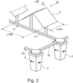
- Figure 2 schematically illustrates an electrical generation system 1 comprising multiple photovoltaic panels.
- the structure 4 comprises primary beams 16 extending in a first direction and secondary beams 17 extending in a direction transverse to that of the primary beams. Beams all are substantially at the same level.
- Floats 2 are arranged at the junction of a primary beam with a secondary beam, at least at each corner of the structure 4.
- Photovoltaic panels 3 are fixed on the secondary beams. In this example, they are arranged in pairs 33 each pair forming a double slope, one of the panels being directed towards the east E and the other towards the west W; this arrangement is particularly advantageous near the equator where the sun of midday is always substantially in plumb with the system.
- the outer beams form, in plan, a square with a side length L4 of nine meters, with four floats, each at a corner of the structure 4.
- the air draft TA measured under a beam, is about one meter and ten centimeters.
- Each pair, seen in plan, has a width L33A of one meter, by two meters length L33B.
- panels 3 are completely opaque, so the solar radiation occultation Q provided by the system 1 is a proportion P of a panel area, seen in plan, related to the extent E of the system.
- the number of pairs 33 is twenty-eight pairs, so that the occultation Q is about fifty percent (50%), which corresponds to a proportion P of the extent E, occupied by twenty-eight pairs of panels, seen in plan.
- UVB B ultraviolet
- a pair of panels forming a dihedral, can be replaced by a single panel, horizontally arranged, of similar dimensions.
- the panels may be installed with a north, south or upward orientation.
- the retractable grid of the nursery can be replaced by a biodegradable net designed to be dropped by the bottom with the spat attached to it.
- the support of the spat may include ropes to which spats are attached. Other support may be used.
Landscapes
- Photovoltaic Devices (AREA)
Abstract
The invention relates to a photovoltaic system 1, which comprises flotation means 2, photovoltaic production means 3 carried by the flotation means. Such a system is advantageously used to protect a coral reef 8 from excess of solar radiation 6.
Description
- The present invention relates to the field of solar energy.
- Coral reef are the cradle of life in the ocean and providing 30% of the biodiversity of the Ocean. Coral reefs are declining around the world to an unprecedent rhythm due to massive coral bleaching. Coral bleaching is due to climate change impact and especially because of the conjecture of two main effects: water temperature increase and exposition to intense light radiation (especially UV). These bleaching events are reported more and more often impacting strongly reef health and a large quantity of coral reef in the world is at risk of disappearing.
- The problem to be solved, and a purpose of the invention, is how to use floating solar systems that will in addition protect coral against bleaching while at the same time allowing decarbonized energy production.
- According to the invention, a solution is a photovoltaic system comprises flotation means, photovoltaic production means and a supporting structure designed to connect flotation means and production means. Production means may comprise several photovoltaic panels. The structure may comprise primary means, which may be primary beams, extending substantially horizontally in a first direction and secondary means, which may be secondary beams, extending in a second direction transverse to the first direction, the panels resting on said secondary means.
- Advantageously, panels are distributed to occupy, seen in plan, a selected proportion of an extent in plan of the system.
- The panels may be translucent. Translucent refers to a panel which allows all or part of an incident light, in particular received sunlight, to pass through it, so that it allows this light to illuminate what is under the shadow of this panel.
- Advantageously, a nursery for spats of coral is disposed under the production means.
- A further object of the invention relates to a shading system for coral reefs, which comprises a photovoltaic system according to the invention. The percentage of shading will be designed to accommodate best the growth of corals.
- In addition, the shading system will also cut the UV over the entire system, reducing stress on corals behind.
- A further object of the invention relates to a system, which comprises a a photovoltaic system according to the invention and support means for a coral spat. Said support means may comprise a rope. Said support means may comprise a grid.
- Also, a method for protecting coral, which may be in different forms such as a pinnacle or a reef, from solar radiation, comprises a step for providing a system according to the invention and a second step for installing the provided system above said corals.
- Embodiments and variants will be described below, as non-limiting examples, with reference to the -attached drawings in which:
- [
Fig. 1 ] is a schematic view, in elevation and perspective, of a photovoltaic production module according to the invention; - [
Fig. 2 ] is a schematic view of a production system wherein the production means comprise several photovoltaic panels; - [
Fig. 3 ] is a schematic view of a production system of the type described infigure 2 , wherein several opaque photovoltaic panels are arranged in a dense layout; and, - [
Fig. 4 ] is a schematic view, similar toFigure 3 , of a system in which panels are arranged in a sparse layout. - Terms as "top", "bottom", "upper" and "lower", "horizontal" and "vertical" and the like may be arbitrarily used in this description and generally refer to positions shown in the figures.
-
Figure 1 illustrates a floatingphotovoltaic system 1 according to the invention. This system comprises flotation means 2, photovoltaic production means and a supportingstructure 4. In the example offigure 1 , the flotation means are in the form of anannular float 2 and the production means are in the form of aphotovoltaic panel 3; the support structure is designed to join thefloat 2 and thepanel 3. Here thepanel 3 is a monoplane panel; it is intended to be oriented substantially in the direction of thesun 6 at its zenith, i.e. in the direction of the south in the northern hemisphere, and in the direction of the north in the southern hemisphere. - The
system 1 is immobilized by mooring and anchoring means 7, substantially above acoral pinnacle 8 to which it provides a shade which protects it from an excess of ultraviolet rays. - In the example of
figure 1 , thesystem 1 also includes anursery 9. The nursery includes a support kept submerged and suspended under thefloat 2. This support is intended to holdcoral spat 10, in the shade of thepanel 3. In the example offigure 1 , the support includes agrid 11 on which thespat 10 rest; the grid is retractable, which allows the spat to be sent to the bottom when considered sufficiently mature. -
Figure 2 schematically illustrates anelectrical generation system 1 comprising multiple photovoltaic panels. In this embodiment, thestructure 4 comprisesprimary beams 16 extending in a first direction andsecondary beams 17 extending in a direction transverse to that of the primary beams. Beams all are substantially at the same level. -
Floats 2 are arranged at the junction of a primary beam with a secondary beam, at least at each corner of thestructure 4.Photovoltaic panels 3 are fixed on the secondary beams. In this example, they are arranged inpairs 33 each pair forming a double slope, one of the panels being directed towards the east E and the other towards the west W; this arrangement is particularly advantageous near the equator where the sun of midday is always substantially in plumb with the system. - Typically, in the illustrated example, the outer beams form, in plan, a square with a side length L4 of nine meters, with four floats, each at a corner of the
structure 4. As illustrated in the plan views ofFigures 3 and 4 , the module, equipped with itspairs 33 ofpanels 3, has an overall extent E, seen in plan, where E = L1A x L1B equal to eleven meters by ten meters. The air draft TA, measured under a beam, is about one meter and ten centimeters. Each pair, seen in plan, has a width L33A of one meter, by two meters length L33B. - In the examples of
Figures 3 and 4 ,panels 3 are completely opaque, so the solar radiation occultation Q provided by thesystem 1 is a proportion P of a panel area, seen in plan, related to the extent E of the system. - In the example shown in
Figure 3 , fortypairs 33 of panels are used, which provide a shading Q of approximately seventy-three percent (73%) of the extent E. - In the example of
Figure 4 , the number ofpairs 33 is twenty-eight pairs, so that the occultation Q is about fifty percent (50%), which corresponds to a proportion P of the extent E, occupied by twenty-eight pairs of panels, seen in plan. - It is also possible to use translucent panels that allow only part of the solar radiation to pass, or part of certain wavelengths of this radiation. At least some ultraviolet wavelengths are blocked by the system, mainly the B ultraviolet (UVB) and we will test the effect on corals.
- Thus, for a substantially total coverage of the area E, for a transparency of twenty percent (20%), i.e. for a panel allowing twenty percent of the radiation that strikes it to pass:
- if the panels are contiguous, over the entire extent E, the occultation Q will be equal to eighty percent (80%); and,
- if the panels cover only fifty percent (50%) of the area E, as is the case in
Figure 4 , the occultation will be forty percent (40%) or eighty percent of the fifty percent covered. - Of course, the invention is not limited to the examples that have been above described. On the contrary, the invention is defined by the following claims.
- It will indeed appear to the person skilled in the art that various modifications can be made to the above-described embodiments, in the light of the teaching which has just been disclosed.
- Thus, a pair of panels, forming a dihedral, can be replaced by a single panel, horizontally arranged, of similar dimensions. Furthermore, the panels may be installed with a north, south or upward orientation.
- The retractable grid of the nursery can be replaced by a biodegradable net designed to be dropped by the bottom with the spat attached to it. Also, the support of the spat may include ropes to which spats are attached. Other support may be used.
Claims (11)
- Photovoltaic system (1), characterized in that it comprises flotation means (2), photovoltaic production means (3) and a supporting structure (4) designed to connect said flotation means and said production means.
- System according to claim 1, wherein the production means (3) comprise several photovoltaic panels.
- System according to claim 2, wherein the structure (4) comprises primary means (16) extending substantially horizontally in a first direction and secondary means (17) extending in a second direction transverse to the first direction, the panels (3) resting on said secondary means.
- System according to one of claims 2 and 3, Wherein the panels are distributed to occupy, seen in plan, a selected proportion (P) of an extent (E) in plan of said system.
- System according to one of claims 2 to 4, wherein the panels are translucent.
- System according to one of claims 1 to 5, wherein a nursery (9) for spats (10) of coral is disposed under the production means.
- A shading system for coral, including blocking some UV rays characterized in that it comprises a system according to any one of claims 1 to 6.
- A coral nursery system, characterized in that it comprises a system according to any one of claims 1 to 5 and support means for a coral spat.
- A nursery system according to claim 8, characterized in that the support means comprise a rope.
- A nursery system according to claim 8 or 9, characterized in that the support means comprise a grid.
- Method for protecting coral (8) from solar radiation, characterized in that it comprises providing a system (1) according to claim 7 and installing said system above said coral.
Priority Applications (1)
| Application Number | Priority Date | Filing Date | Title |
|---|---|---|---|
| EP23315397.2A EP4546643A1 (en) | 2023-10-24 | 2023-10-24 | Device and associated method using solar energy and adapted for the protection of corals |
Applications Claiming Priority (1)
| Application Number | Priority Date | Filing Date | Title |
|---|---|---|---|
| EP23315397.2A EP4546643A1 (en) | 2023-10-24 | 2023-10-24 | Device and associated method using solar energy and adapted for the protection of corals |
Publications (1)
| Publication Number | Publication Date |
|---|---|
| EP4546643A1 true EP4546643A1 (en) | 2025-04-30 |
Family
ID=88833823
Family Applications (1)
| Application Number | Title | Priority Date | Filing Date |
|---|---|---|---|
| EP23315397.2A Pending EP4546643A1 (en) | 2023-10-24 | 2023-10-24 | Device and associated method using solar energy and adapted for the protection of corals |
Country Status (1)
| Country | Link |
|---|---|
| EP (1) | EP4546643A1 (en) |
Citations (4)
| Publication number | Priority date | Publication date | Assignee | Title |
|---|---|---|---|---|
| CN105186977A (en) * | 2015-08-26 | 2015-12-23 | 浙江融聚节能设备制造有限公司 | Waterborne solar photovoltaic power generation system |
| WO2016089836A1 (en) * | 2014-12-01 | 2016-06-09 | 4CSOLAR, Inc. | Floating solar panel systems |
| CN206364749U (en) * | 2017-01-11 | 2017-07-28 | 苏州奇点新能源科技有限公司 | A kind of water surface photovoltaic floating raft type flotation gear |
| CN114982690A (en) * | 2022-05-31 | 2022-09-02 | 深圳市珊瑚礁生态修复有限公司 | Coral breeding device |
-
2023
- 2023-10-24 EP EP23315397.2A patent/EP4546643A1/en active Pending
Patent Citations (4)
| Publication number | Priority date | Publication date | Assignee | Title |
|---|---|---|---|---|
| WO2016089836A1 (en) * | 2014-12-01 | 2016-06-09 | 4CSOLAR, Inc. | Floating solar panel systems |
| CN105186977A (en) * | 2015-08-26 | 2015-12-23 | 浙江融聚节能设备制造有限公司 | Waterborne solar photovoltaic power generation system |
| CN206364749U (en) * | 2017-01-11 | 2017-07-28 | 苏州奇点新能源科技有限公司 | A kind of water surface photovoltaic floating raft type flotation gear |
| CN114982690A (en) * | 2022-05-31 | 2022-09-02 | 深圳市珊瑚礁生态修复有限公司 | Coral breeding device |
Non-Patent Citations (1)
| Title |
|---|
| ESSAK LAURA ET AL: "Floating Photovoltaics: A Review", CLEAN TECHNOLOGIES, vol. 4, no. 3, 8 August 2022 (2022-08-08), pages 752 - 769, XP093133518, ISSN: 2571-8797, DOI: 10.3390/cleantechnol4030046 * |
Similar Documents
| Publication | Publication Date | Title |
|---|---|---|
| ES3038157T3 (en) | Solar power generation plant installable on agricultural installations | |
| KR101075161B1 (en) | Floating Offshore Solar Power Plant and Its Application to Marine Farms | |
| KR101682856B1 (en) | Flexible type floating solar power generating system | |
| Perna et al. | Design considerations for agrophotovoltaic systems: maintaining PV area with increased crop yield | |
| CN112701994B (en) | A three-dimensional development structure of marine resources based on the complementarity of wind, light and fisheries | |
| KR101171683B1 (en) | Connecting structure of the photovoltaic power generator with connecting hinge | |
| KR101642387B1 (en) | Floating solar power generating system | |
| CN103314262A (en) | Buoyant solar panel, and solar power plant consisting of an assembly of said panels | |
| WO2017195995A1 (en) | Pillar-fixed flexible offshore photovoltaic power generation system | |
| US11245352B2 (en) | Floating photovoltaic module | |
| ES2851074T3 (en) | Directional Solar Panel Assembly | |
| EP3599650A1 (en) | High-efficiency translucent solar module assembly | |
| EP3982713A1 (en) | Greenhouse with photovoltaic system | |
| Ma et al. | Design of floating photovoltaic power plant and its environmental effects in different stages: A review | |
| CN202231644U (en) | Solar device on water | |
| CZ2020617A3 (en) | Spatial structure of a photovoltaic cell or solar concentrator | |
| WO2017118998A1 (en) | Floating solar platform | |
| JP2014097002A (en) | Greenhouse | |
| JP3196882U (en) | Ground-installed solar power generation equipment | |
| JP2022092587A (en) | Reflection type photovoltaic power generation system | |
| EP2339084A2 (en) | Lighting and shade components for building exteriors | |
| KR20200004643A (en) | Angle measuring device for solar panels | |
| CN103456816B (en) | A kind of application process of tubular photovoltaic electrification component | |
| CN214337868U (en) | Synergistic mulching film mechanism applied to photovoltaic power station and mulching film synergistic detection system | |
| JP2015228729A (en) | Solar panel site |
Legal Events
| Date | Code | Title | Description |
|---|---|---|---|
| PUAI | Public reference made under article 153(3) epc to a published international application that has entered the european phase |
Free format text: ORIGINAL CODE: 0009012 |
|
| STAA | Information on the status of an ep patent application or granted ep patent |
Free format text: STATUS: THE APPLICATION HAS BEEN PUBLISHED |
|
| AK | Designated contracting states |
Kind code of ref document: A1 Designated state(s): AL AT BE BG CH CY CZ DE DK EE ES FI FR GB GR HR HU IE IS IT LI LT LU LV MC ME MK MT NL NO PL PT RO RS SE SI SK SM TR |
|
| STAA | Information on the status of an ep patent application or granted ep patent |
Free format text: STATUS: REQUEST FOR EXAMINATION WAS MADE |
|
| 17P | Request for examination filed |
Effective date: 20251030 |