EP4546627A1 - Llc voltage converter - Google Patents
Llc voltage converter Download PDFInfo
- Publication number
- EP4546627A1 EP4546627A1 EP23205224.1A EP23205224A EP4546627A1 EP 4546627 A1 EP4546627 A1 EP 4546627A1 EP 23205224 A EP23205224 A EP 23205224A EP 4546627 A1 EP4546627 A1 EP 4546627A1
- Authority
- EP
- European Patent Office
- Prior art keywords
- llc
- voltage converter
- voltage
- converter
- output
- Prior art date
- Legal status (The legal status is an assumption and is not a legal conclusion. Google has not performed a legal analysis and makes no representation as to the accuracy of the status listed.)
- Pending
Links
Images

Classifications
-
- H—ELECTRICITY
- H02—GENERATION; CONVERSION OR DISTRIBUTION OF ELECTRIC POWER
- H02M—APPARATUS FOR CONVERSION BETWEEN AC AND AC, BETWEEN AC AND DC, OR BETWEEN DC AND DC, AND FOR USE WITH MAINS OR SIMILAR POWER SUPPLY SYSTEMS; CONVERSION OF DC OR AC INPUT POWER INTO SURGE OUTPUT POWER; CONTROL OR REGULATION THEREOF
- H02M1/00—Details of apparatus for conversion
- H02M1/0003—Details of control, feedback or regulation circuits
- H02M1/0009—Devices or circuits for detecting current in a converter
-
- H—ELECTRICITY
- H02—GENERATION; CONVERSION OR DISTRIBUTION OF ELECTRIC POWER
- H02M—APPARATUS FOR CONVERSION BETWEEN AC AND AC, BETWEEN AC AND DC, OR BETWEEN DC AND DC, AND FOR USE WITH MAINS OR SIMILAR POWER SUPPLY SYSTEMS; CONVERSION OF DC OR AC INPUT POWER INTO SURGE OUTPUT POWER; CONTROL OR REGULATION THEREOF
- H02M3/00—Conversion of DC power input into DC power output
- H02M3/01—Resonant DC/DC converters
-
- H—ELECTRICITY
- H02—GENERATION; CONVERSION OR DISTRIBUTION OF ELECTRIC POWER
- H02M—APPARATUS FOR CONVERSION BETWEEN AC AND AC, BETWEEN AC AND DC, OR BETWEEN DC AND DC, AND FOR USE WITH MAINS OR SIMILAR POWER SUPPLY SYSTEMS; CONVERSION OF DC OR AC INPUT POWER INTO SURGE OUTPUT POWER; CONTROL OR REGULATION THEREOF
- H02M3/00—Conversion of DC power input into DC power output
- H02M3/22—Conversion of DC power input into DC power output with intermediate conversion into AC
- H02M3/24—Conversion of DC power input into DC power output with intermediate conversion into AC by static converters
- H02M3/28—Conversion of DC power input into DC power output with intermediate conversion into AC by static converters using discharge tubes with control electrode or semiconductor devices with control electrode to produce the intermediate AC
- H02M3/285—Single converters with a plurality of output stages connected in parallel
-
- H—ELECTRICITY
- H02—GENERATION; CONVERSION OR DISTRIBUTION OF ELECTRIC POWER
- H02M—APPARATUS FOR CONVERSION BETWEEN AC AND AC, BETWEEN AC AND DC, OR BETWEEN DC AND DC, AND FOR USE WITH MAINS OR SIMILAR POWER SUPPLY SYSTEMS; CONVERSION OF DC OR AC INPUT POWER INTO SURGE OUTPUT POWER; CONTROL OR REGULATION THEREOF
- H02M3/00—Conversion of DC power input into DC power output
- H02M3/22—Conversion of DC power input into DC power output with intermediate conversion into AC
- H02M3/24—Conversion of DC power input into DC power output with intermediate conversion into AC by static converters
- H02M3/28—Conversion of DC power input into DC power output with intermediate conversion into AC by static converters using discharge tubes with control electrode or semiconductor devices with control electrode to produce the intermediate AC
- H02M3/325—Conversion of DC power input into DC power output with intermediate conversion into AC by static converters using discharge tubes with control electrode or semiconductor devices with control electrode to produce the intermediate AC using devices of a triode or a transistor type requiring continuous application of a control signal
- H02M3/335—Conversion of DC power input into DC power output with intermediate conversion into AC by static converters using discharge tubes with control electrode or semiconductor devices with control electrode to produce the intermediate AC using devices of a triode or a transistor type requiring continuous application of a control signal using semiconductor devices only
- H02M3/33569—Conversion of DC power input into DC power output with intermediate conversion into AC by static converters using discharge tubes with control electrode or semiconductor devices with control electrode to produce the intermediate AC using devices of a triode or a transistor type requiring continuous application of a control signal using semiconductor devices only having several active switching elements
- H02M3/33571—Half-bridge at primary side of an isolation transformer
-
- H—ELECTRICITY
- H02—GENERATION; CONVERSION OR DISTRIBUTION OF ELECTRIC POWER
- H02M—APPARATUS FOR CONVERSION BETWEEN AC AND AC, BETWEEN AC AND DC, OR BETWEEN DC AND DC, AND FOR USE WITH MAINS OR SIMILAR POWER SUPPLY SYSTEMS; CONVERSION OF DC OR AC INPUT POWER INTO SURGE OUTPUT POWER; CONTROL OR REGULATION THEREOF
- H02M3/00—Conversion of DC power input into DC power output
- H02M3/22—Conversion of DC power input into DC power output with intermediate conversion into AC
- H02M3/24—Conversion of DC power input into DC power output with intermediate conversion into AC by static converters
- H02M3/28—Conversion of DC power input into DC power output with intermediate conversion into AC by static converters using discharge tubes with control electrode or semiconductor devices with control electrode to produce the intermediate AC
- H02M3/325—Conversion of DC power input into DC power output with intermediate conversion into AC by static converters using discharge tubes with control electrode or semiconductor devices with control electrode to produce the intermediate AC using devices of a triode or a transistor type requiring continuous application of a control signal
- H02M3/335—Conversion of DC power input into DC power output with intermediate conversion into AC by static converters using discharge tubes with control electrode or semiconductor devices with control electrode to produce the intermediate AC using devices of a triode or a transistor type requiring continuous application of a control signal using semiconductor devices only
- H02M3/3353—Conversion of DC power input into DC power output with intermediate conversion into AC by static converters using discharge tubes with control electrode or semiconductor devices with control electrode to produce the intermediate AC using devices of a triode or a transistor type requiring continuous application of a control signal using semiconductor devices only having at least two simultaneously operating switches on the input side, e.g. "double forward" or "double (switched) flyback" converter
Definitions
- This disclosure relates to DC to DC voltage conversion using LLC voltage converters.
- the current design of LLC converters for DC to DC voltage converters for use in parallel arrangements has various drawbacks.
- the current design either has a master controller, configured to control operation of each parallel LLC converter, or has a master/slave arrangement, wherein one of the LLC converters is arranged to operate as a master controller.
- both cases have various downsides. For instance, in both cases replacement of a LLC converter, for example as a result of failure, requires reconfiguration of the master controller, the replacement LLC converter or the master LLC converter.
- the replacement LLC converter in a master/slave arrangement must be configured as either a master or a slave.
- designing a system to have several LLC converters in parallel requires configuration of the controller or master LLC converter for use with a certain number of LLC converters. This offers limited, if any, flexibility in the design of the system. For instance, hardware and/or software reconfiguration of the system may be necessary in order to change the number of parallel LLC converters used.
- the present disclosure provides a LLC voltage converter for converting a DC input voltage to a DC output voltage, the LLC voltage converter comprising:
- the first, input, winding may be arranged so as to receive the DC input voltage, e.g. indirectly, and induce a voltage across the second, output, winding.
- the first winding may be arranged on an input side of the LLC voltage converter and the second winding may be arranged on an output side of the LLC voltage converter.
- the LLC voltage converter may comprise a voltage switching circuit element, comprising: an input configured to be connected to the DC input voltage; and an output.
- the voltage switching circuit element may be any circuit element suitable for receiving the DC input voltage at the input of the voltage switching circuit and providing an alternating voltage at the output of the voltage switching circuit.
- the alternating voltage may alternate between a high value and a low value at a switching frequency.
- the alternating voltage may be a square-wave which alternates between a high value and a low value.
- the voltage switching circuit may, for example, be a half-bridge or a full-bridge.
- the voltage switching circuit may include a half-bridge and may be arranged to selectively connect and disconnect the DC input voltage to its output to provide an alternating voltage, which alternates between zero and the DC input voltage.
- the LLC voltage converter may comprise a resonant tank circuit element, comprising: an input, for example connected to the output of the voltage switching circuit element; and the first (input) winding of the transformer.
- the resonant tank circuit element includes a capacitance, which may be in series with the transformer. In some examples, the resonant tank circuit element also includes an inductance in series with the transformer. The resonant tank circuit element may be configured to resonate at the switching frequency of the alternating voltage provided by the voltage switching circuit element.
- the LLC voltage converter may comprise an output circuit element, comprising: the second (output) winding of the transformer; and an output configured to be connected to a load across which the DC output voltage is applied.
- the output circuit element may be any circuit element suitable for rectifying a secondary voltage across the second winding of the transformer and/or filtering out AC components of the secondary voltage.
- the output circuit element may include a half-wave rectifier, a full-wave rectifier or a rectifier with a zeta topology.
- the transformer may be a tapped transformer with the second winding having a first portion proximate to a first end, a second portion proximate to a second end and a connection point between the first portion and the second portion.
- the tapped transformer may be a centre-tapped transformer, wherein the first portion and second portion are the same length.
- the output circuit element may include a capacitor connected to the connection point between the first portion and the second portion.
- the capacitor may also be connected to both the first end and the second end.
- a first diode may be arranged in series with the capacitor and the first end of the second winding of the transformer.
- a second diode may be arranged in series with the capacitor and the second end of the second winding of the transformer.
- the output circuit element may be arranged such that the load is able to be connected in parallel with the capacitor.
- the LLC voltage converter is arranged to send the parameter relating to the output current of the LLC converter to the at least one other LLC voltage converter configured in parallel with the LLC voltage converter, when the LLC voltage converter is in use.
- the LLC voltage converter comprises an output voltage sensor arranged to measure the DC output voltage and arranged to provide a measurement of the DC output voltage to the controller.
- the controller is arranged to control the LLC voltage converter at least partially based on the measurement of the DC output voltage.
- the controller may be arranged to control operation of the LLC voltage converter so as to achieve a certain DC output voltage.
- the controller is arranged to control the LLC voltage converter by controlling operation of the voltage switching circuit element.
- the voltage switching circuit element may be arranged to provide an alternating voltage, which alternates between a high value and a low value at a switching frequency, at the output of the voltage switching circuit element.
- the alternating voltage may be a square-wave which alternates between a high value and a low value.
- the controller is arranged to control the LLC voltage converter by controlling the switching frequency of the alternating voltage.
- the transformer is a step-down transformer.
- the DC input voltage may be higher than the DC output voltage.
- the LLC voltage converter comprises a primary transformer voltage sensor arranged to measure a primary transformer voltage across the first winding of the transformer and to provide a measurement of the primary transformer voltage to the controller.
- the controller is arranged to determine the parameter relating to the output current of the LLC converter at least partially based on the measurement of the primary transformer voltage. For example, the controller may be arranged to use the primary current and the primary transformer voltage to determine a reflected secondary current through the first winding of the transformer. The reflected secondary current may be the current induced in the first winding of the transformer by the second winding of the transformer. The controller may be arranged to determine the secondary current, for example the current through the second winding of the transformer, based on the reflected secondary current.
- the controller is arranged to determine the parameter relating to the output current of the LLC voltage converter by determining a secondary current through the second winding of the transformer.
- the parameter relating to the output current of the LLC voltage converter may be the secondary current through the secondary winding of the transformer or an average value of secondary current through the secondary winding of the transformer.
- the parameter relating to the output current of the LLC voltage converter may be the output current of the LLC voltage converter. This may be determined by the controller, for example, by determining a secondary current through the secondary winding of the transformer and using the secondary current to determine the output current.
- the controller is arranged to balance the output currents between the LLC voltage converter and each of the at least one other LLC voltage converter.
- the controller is arranged to receive a parameter relating to an output current of at least two other LLC voltage converters.
- the controller is arranged to control the LLC voltage converter at least partially based on the parameter relating to the output current of the LLC converter and the parameters relating to the output currents of the at least two other LLC voltage converters.
- the controller may be arranged to balance the output currents between the LLC voltage converter and each of the at least two other LLC voltage converters.
- the present disclosure also provides a system for converting a DC input voltage to a DC output voltage comprising:
- system further comprises:
- the present disclosure also provides a method of controlling a LLC voltage converter for converting a DC input voltage to a DC output voltage, the LLC voltage converter comprising:
- the LLC voltage converter may be a LLC voltage converter according to any example described herein. Hence, various of the optional features described in relation to one or other examples may apply equally to any of the other examples.
- the LLC voltage converter may comprise a voltage switching circuit element, comprising: an input configured to be connected to the DC input voltage; and an output.
- the LLC voltage converter may comprise a resonant tank circuit element, comprising: an input connected to the output of the voltage switching circuit element; and the first (input) winding of the transformer.
- the LLC voltage converter may comprise an output circuit element, comprising: the second (output) winding of the transformer; and an output configured to be connected to a load across which the DC output voltage is applied.
- the method further comprises sending the parameter relating to the output current of the LLC voltage converter to the at least one other LLC voltage converter.
- the LLC voltage converter comprises an output voltage sensor arranged to measure the DC output voltage and arranged to provide a measurement of the DC output voltage to the controller.
- the method comprises measuring the DC output voltage and controlling the LLC voltage converter at least partially based on the measuring of the DC output voltage.
- controlling the LLC voltage converter comprises controlling operation of the voltage switching circuit element.
- the voltage switching circuit element is arranged to provide an alternating voltage, which alternates between a high value and a low value at a switching frequency, at the output of the voltage switching circuit element.
- controlling the LLC voltage converter comprises varying the switching frequency of the alternating voltage.
- the transformer is a step-down transformer.
- the DC input voltage may be higher than the DC output voltage.
- the LLC voltage converter comprises a primary transformer voltage sensor arranged to measure a primary transformer voltage across the first winding of the transformer and to provide a measurement of the primary transformer voltage to the controller.
- the method comprises measuring the primary transformer voltage.
- determining the parameter relating to the output current of the LLC voltage converter comprises determining the parameter based on the measuring of the primary transformer voltage.
- the method may include using the primary current and the primary transformer voltage to determine a reflected secondary current through the first winding of the transformer.
- the reflected secondary current may be the current induced in the first winding of the transformer by the second winding of the transformer.
- the method may comprise determining the secondary current, for example the current through the second winding of the transformer, based on the reflected secondary current.
- determining the parameter relating to the output current of the LLC voltage converter comprises determining the parameter by determining a secondary current through the second winding of the transformer.
- the parameter relating to the output current of the LLC voltage converter may be the secondary current through the secondary winding of the transformer or an average value of secondary current through the secondary winding of the transformer.
- the parameter relating to the output current of the LLC voltage converter may be the output current of the LLC voltage converter.
- the method may comprise, for example, determining a secondary current through the secondary winding of the transformer and using the secondary current to determine the output current.
- the method comprises balancing the output currents between the LLC voltage converter and each of the at least one other LLC voltage converter.
- the LLC voltage converter is configured in parallel with at least two other LLC voltage converters.
- the method comprises receiving a parameter relating to an output current of each of the at least two other LLC voltage converters configured in parallel with the LLC voltage converter; and controlling the LLC voltage converter at least partially based on the parameters relating to output currents of each of the at least two other LLC voltage converters configured in parallel with the LLC voltage converter.
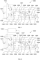
- FIG. 1 shows a LLC voltage converter 1000 arranged to convert a DC input voltage V in 1001 to a DC output voltage V out 1002.
- the LLC voltage converter 1000 has a voltage switching circuit element 1100, a resonant tank circuit element 1200 and an output circuit element 1300.
- voltage switching circuit element 1100 has two switches Q 1 1102 and Q 2 1103 arranged in series.
- the voltage switching circuit element 1100 is arranged to receive the DC input voltage V in 1001 across both switches Q 1 1102 and Q 2 1103, and output an alternating voltage V alt 1101 across the second switch Q 2 1103.
- the voltage V alt 1101 at the output of the voltage switching circuit element 1100 is V in 1001.
- the voltage switching circuit element 1100 is arranged to transition between these two switching states to alternate the alternating voltage V alt 1101 between zero and V in 1001.
- the voltage switching circuit element 1100 is a half-bridge and is arranged to selectively connect and disconnect the DC input voltage V in 1001 to its output, thus alternating the alternating voltage V alt 1101 between zero and V in 1001.
- a different voltage switching circuit element may be used.
- a full-bridge may be used, which may be arranged to alternate the alternating voltage V alt 1101 between negative V in and positive V in .
- direct measurement of I sec 1305 may have various draw-backs.
- step-down applications the current is stepped-up, thus resulting in a high secondary current I sec 1305.
- direct measurement of the secondary current I sec 1305 in step-down applications may result in high power losses.
- the secondary current I sec 1305 through the second winding of the transformer T 1201 causes a reflected secondary current I sec' 1206 in the first winding of the transformer T 1201 due to their mutual inductance.
- the relationship between the secondary current I sec 1305 and the reflected secondary current I sec' 1206 is determined by the turns ratio of the transformer T 1201. Therefore, if the reflected secondary current I sec' 1206 is known, the secondary current I sec 1305 may be determined without direct measurement.
- the primary current I prim 1207 through the first winding of the transformer T 1201 is the sum of the reflected secondary current I sec' 1206 and the magnetising current of the transformer I mag 1205.
- I mag ⁇ 0 t V prim L mag dt
- Equation 1 defines the relationship between the value of the magnetising inductance L mag 1202 of the transformer T 1201, the magnetising current I mag 1205 and the primary voltage V prim 1204. Equation 1 may be used to calculate the magnetising current I mag 1205.
- the primary current I prim 1207 may be measured directly.
- the reflected secondary current I sec' 1206 may be determined by subtracting the magnetising current I mag 1205 from the primary current I prim 1207. Therefore, a current feedback loop may be used to control the output current I out 1004 of the LLC converter 1000, based on the secondary current I sec 1305, without direct measurement of either of these currents. This may be preferable to direct measurement of the secondary current I sec 1305 or the output current I out 1004. For example, in step-down applications where direct measurement of the secondary current I sec 1305 or the output current I out 1004 may result in high power losses.
- FIG 2 shows a LLC converter 1000' which is a variation of the LLC converter 1000 shown in Figure 1 .
- This variation 1000' includes a current sensor 1401 in series with the first winding of the transformer T 1201, which is arranged to measure the primary current I prim 1207 through the first winding of the transformer T 1201.
- the LLC converter 1000' also includes a controller 1400.
- the controller 1400 is arranged to receive the measurement of the primary current I prim 1207 from the current sensor 1401 and control operation of the LLC converter 1000' based on the primary current I prim 1207.
- the controller 1400 may also receive a measurement from a voltage sensor (not shown) which is arranged to measure the primary voltage V prim 1204.
- the controller is arranged to determine the reflected secondary current I sec' 1206, the secondary current I sec 1305, and/or the output current I out 1004.
- operation of the LLC circuit element 1000' is controlled by controlling the switching frequency of the first Q 1 1102 and second Q 2 1103 switches within the resonant tank inductive region. Assuming everything else remains unchanged, increasing the switching frequency decreases the secondary current I sec 1305 and decreasing the switching frequency increases the secondary current I sec 1305.
- Figure 3 shows an arrangement which includes a first LLC converter 301 and a second LLC converter 302 in parallel.
- the first 301 and/or second 302 LLC converter may be similar to the LLC converter 1000' shown in Figure 2 .
- Parallelisation of multiple DC-DC voltage converters may have various advantages, including reducing the magnitude of the current through an equivalent individual DC-DC voltage converter.
- first 301 and second 302 LLC converters may require that the first 301 and second 302 LLC converters are operated differently in order to balance the first output current I out1 305 and second output current I out2 306.
- the first 301 and second 302 LLC converter may need to operate with a different switching frequency to produce the same output current.
- This may not be possible by controlling the first 301 and second 302 LLC converters using only the output voltage V out 304, as this is common to both converters 301, 302. Therefore, the first 301 and second 302 LLC converters must be controlled using another parameter, indicative of the first output current I out1 305 and second output current I out2 306. As previously explained, particularly in step-down applications, direct measurement of these currents may result in high power losses.
- Each of the first 301 and the second 302 LLC converters of Figure 3 are controlled based on the current I prim1 307 through the first winding of the transformer T 1 309 of the first LLC converter 301 and the current I prim2 308 through the first winding of the transformer T 2 310 of the second LLC converter 302.
- these currents I prim1 307 and I prim2 308 are related to the output currents I out1 305 and I out2 306. Therefore, controlling operation of the first 301 and second 302 LLC converters based on these currents I prim1 307 and I prim2 may enable current balancing between the first 301 and second 302 LLC converters without requiring direct measurement of the first output current I out1 305 and the second output current I out2 306.
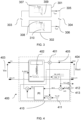
- FIG 4 shows an LLC converter 400 such as the first LLC converter 301 and/or the second LLC convert 302 of Figure 3 .
- the LLC converter 400 is configured to be arranged in parallel with at least one other LLC converter and is arranged to convert a DC input voltage V in 403 to a DC output voltage V out 404.
- the LLC converter 400 is a step-down converter.
- the LLC converter 400 includes a voltage sensor 401 arranged to measure the output voltage V out 404.
- the LLC converter 400 also includes a current sensor (not shown) such as current sensor 1401 of Figure 2 arranged to measure a primary current through a first winding of the transformer T 402.
- the LLC converter 400 also has another voltage sensor (not shown) arranged to measure the primary voltage across the first winding of the transformer T 402.
- the LLC converter 400 has a controller 410.
- the controller is arranged to receive the voltage measurement from the output voltage sensor 401 and compare this to a reference voltage 411.
- the controller is arranged to vary operation of the LLC converter 400 based on the difference between the reference voltage and the measurement from the output voltage sensor 401.
- the controller 410 is also arranged to receive a measurement from the current sensor (not shown) of the primary current through the first winding of the transformer T 402.
- the controller 410 is also arranged to receive a measurement from the primary voltage sensor (not shown) of the primary voltage across the first winding of the transformer T 402.
- the controller 410 is arranged to determine the reflected secondary current I sec' , and thus the secondary current I sec , using the approach outlined earlier.
- This secondary current I sec is proportional to an output current I o_1 405 of the LLC converter 400.
- the controller 410 is arranged to determine an average value of the secondary current I sec and provide this as an output current reference I o_1_calc 412 to at least one other LLC converter in parallel with the LLC converter 400 of Figure 4 .
- This other LLC converter may be similar to the LLC converter 400 shown in Figure 4 .
- the controller 410 is arranged to receive an input current reference I o_2_calc 413 which corresponds to the average value of the secondary current I sec of another LLC converter in parallel with the LLC converter 400 of Figure 4 .
- the controller 410 is configured to compare the average value I o_1_calc 412 of the secondary current I sec of the LLC converter 400 shown in Figure 4 and the average value I o_2_calc 413 of the secondary current I sec of the LLC converter that is arranged in parallel with the LLC converter 400 shown in Figure 4 .
- the controller 410 is arranged to control operation of the LLC converter 400 based on the difference between these values, for example in order to balance the output current I o_1 405 between the parallel LLC converters. In this example, operation of the LLC converter 400 is controlled by changing the switching frequency of the LLC converter 400.
- the controller 410 may be arranged to receive a parameter indicative of the secondary current I sec from each of the plurality of LLC converters and control operation of the LLC converter 400 based on all of these values. This may allow for a modular LLC converter design which allows a LLC converter to be used in situations that require anywhere from just one LLC converter to several LLC converters arranged in parallel with little or no modification to the LLC converter required. Hence, it may not be necessary to have a different design for each use case.
- the controller 410 is arranged to control operation of the LLC converter 400 based on the difference between the average value I o_1_calc 412 of the secondary current I sec of the LLC converter 400 shown in Figure 4 and the mean of the average values I o_n_calc 412 of the secondary currents I sec of the other LLC converters.
- This approach may enable balancing of the output current I o_n between several parallel LLC converters arranged in parallel, such as LLC converter 400.
- each LLC converter 400 arranged in parallel may have its own controller 410, each LLC converter 400 may be controlled independently. Therefore, a master controller, arranged to control each of the parallel LLC converters, may not be necessary. Hence, replacement of a LLC converter, for example due to failure, may also be more straightforward if the LLC converter has its own controller.
- the disclosed design of a LLC converter may be particularly useful to balance the output current across multiple parallel LLC converters when used to step-down a higher voltage to a lower voltage, as direct measurement of the output current of each LLC converter, which may result in high power losses, is not necessary. For example, when stepping down a voltage of approximately 540 volts to a voltage of approximately 28 volts. Therefore, a LLC converter 200; 300; 400; 500, such as those shown in Figures 2 to 4 , would be particularly useful in aircrafts where DC power distribution is used.
- the high voltages may be used in the aircraft's propulsion systems, while the lower voltages may be used elsewhere in the aircraft.
- Galvanic isolation between the high voltage load is also important to ensure proper grounding protection and safety.
- using a transformer to isolate the high voltage side of the LLC converter from the low voltage side of the LLC converter may provide a safer LLC converter design.
- FIG 5 shows a method 500 of operating a LLC converter, such as the LLC converters shown in Figures 2 to 4 .
- the method 500 includes a first step 501 of measuring the current through the first winding of the transformer.
- the method 500 includes a second step 502 of determining a parameter relating to an output current of the LLC voltage converter based on the measured current.
- the parameter relating to an output current of the LLC voltage converter is an average value of the secondary current, through the second winding of the transformer.
- different parameters may be used, such as the output current itself or the secondary current itself.
- the LLC voltage converter has a primary transformer voltage sensor arranged to measure a primary transformer voltage across the first winding of the transformer and to provide a measurement of the primary transformer voltage to the controller.
- the method 500 includes measuring the primary transformer voltage and the second step 502 includes determining the parameter using the measured primary transformer voltage. For example, by using equation 1 to determine the magnetising current and deducting this from the measured primary current to determine the reflected secondary current, and thus the secondary current itself.
- the parameter relating to the output current of the LLC voltage converter is an average value of secondary current through the secondary winding of the transformer.
- the method 500 includes a third step 503 of receiving a parameter relating to an output current of another parallel LLC voltage converter, such as the voltage converters of Figures 2 to 4 .
- the parameter in this example is the same parameter as determined in the second step 502, but for the other LLC voltage converters.
- the method 500 includes a fourth step 504 of controlling the LLC voltage converter based on the parameter relating to the output current of the LLC voltage converter and the parameter relating to the output current of the at least one other LLC voltage converter. For example, in order to balance the current between multiple parallel LLC voltage converters.
- the LLC voltage converter is in parallel with two other LLC voltage converters.
- the method 500 includes receiving a parameter relating to an output current of each of the two other LLC voltage converters in parallel with the LLC voltage converter and averaging these parameters to have a an average parameter, which in this example is the mean of the average secondary currents through the two other parallel LLC voltage converters.
- controlling the LLC voltage converter includes using this average parameter to balance the output currents between the parallel LLC voltage converters.
- controlling the LLC voltage converter includes controlling operation of the voltage switching circuit element. For example, by varying the switching frequency of the alternating voltage.
- the LLC voltage converter comprises an output voltage sensor arranged to measure the DC output voltage and arranged to provide a measurement of the DC output voltage to the controller.
- the method in this example includes measuring the DC output voltage and controlling the LLC voltage converter based on the measured DC output voltage. For example, in order to achieve a certain output voltage.
- the method 500 also includes a fifth step 505 of sending the parameter relating to the output current of the LLC voltage converter to the at least one other LLC voltage converter.
Landscapes
- Engineering & Computer Science (AREA)
- Power Engineering (AREA)
- Dc-Dc Converters (AREA)
Abstract
A LLC voltage converter (1000') for converting a DC input voltage (1001) to a DC output voltage (1002). The LLC voltage converter (1000') includes a transformer (1201), a controller (1400) and a current sensor (1401). The current sensor (1401) provides a measurement of the current (1207) through a first winding of a transformer (1201) to the controller (1400). The controller (1400) determines a parameter relating to an output current (1004) of the LLC voltage (1000') converter using the current measurement. The controller (1400) also receives a parameter relating to an output current of at least one other LLC voltage converter, configured in parallel with the LLC voltage converter (1000'). The controller (1400) is arranged to control the LLC voltage converter (1000') based on both the parameter relating to the output current of the LLC converter (1000') and the parameter relating to the output current of the other LLC voltage converter.
Description
- This disclosure relates to DC to DC voltage conversion using LLC voltage converters.
- When using a LLC converter to perform DC to DC voltage conversion, it may be important to determine and/or control the output current of the LLC converter. For example, when using multiple LLC converters in parallel, it may be important to balance the current between the parallel LLC DC to DC voltage converters. However, direct measurement of the output current from a LLC converter in step-down applications may lead to significant power losses, as a result of the high output current.
- The current design of LLC converters for DC to DC voltage converters for use in parallel arrangements has various drawbacks. For example, the current design either has a master controller, configured to control operation of each parallel LLC converter, or has a master/slave arrangement, wherein one of the LLC converters is arranged to operate as a master controller.
- Both cases have various downsides. For instance, in both cases replacement of a LLC converter, for example as a result of failure, requires reconfiguration of the master controller, the replacement LLC converter or the master LLC converter. For example, the replacement LLC converter in a master/slave arrangement must be configured as either a master or a slave.
- Also, designing a system to have several LLC converters in parallel requires configuration of the controller or master LLC converter for use with a certain number of LLC converters. This offers limited, if any, flexibility in the design of the system. For instance, hardware and/or software reconfiguration of the system may be necessary in order to change the number of parallel LLC converters used.
- The present disclosure provides a LLC voltage converter for converting a DC input voltage to a DC output voltage, the LLC voltage converter comprising:
- a transformer comprising a first input winding and a second output winding;
- a current sensor configured to measure a primary current through the first winding of the transformer; and
- a controller;
- wherein the current sensor is arranged to provide a measurement of the primary current to the controller;
- wherein the controller is arranged to determine a parameter relating to an output current of the LLC voltage converter at least partially based on the measurement of the primary current;
- wherein the controller is arranged to receive a parameter relating to an output current of at least one other LLC voltage converter configured in parallel with the LLC voltage converter, when the LLC voltage converter is in use; and
- wherein the controller is arranged to control the LLC voltage converter at least partially based on the parameter relating to the output current of the LLC converter and the parameter relating to the output current of the at least one other LLC voltage converter.
- The first, input, winding may be arranged so as to receive the DC input voltage, e.g. indirectly, and induce a voltage across the second, output, winding. For example, the first winding may be arranged on an input side of the LLC voltage converter and the second winding may be arranged on an output side of the LLC voltage converter.
- The LLC voltage converter may comprise a voltage switching circuit element, comprising: an input configured to be connected to the DC input voltage; and an output.
- The voltage switching circuit element may be any circuit element suitable for receiving the DC input voltage at the input of the voltage switching circuit and providing an alternating voltage at the output of the voltage switching circuit. The alternating voltage may alternate between a high value and a low value at a switching frequency. For example, the alternating voltage may be a square-wave which alternates between a high value and a low value.
- The voltage switching circuit may, for example, be a half-bridge or a full-bridge. For instance, the voltage switching circuit may include a half-bridge and may be arranged to selectively connect and disconnect the DC input voltage to its output to provide an alternating voltage, which alternates between zero and the DC input voltage.
- The LLC voltage converter may comprise a resonant tank circuit element, comprising: an input, for example connected to the output of the voltage switching circuit element; and the first (input) winding of the transformer.
- The resonant tank circuit element includes a capacitance, which may be in series with the transformer. In some examples, the resonant tank circuit element also includes an inductance in series with the transformer. The resonant tank circuit element may be configured to resonate at the switching frequency of the alternating voltage provided by the voltage switching circuit element.
- The LLC voltage converter may comprise an output circuit element, comprising: the second (output) winding of the transformer; and an output configured to be connected to a load across which the DC output voltage is applied.
- The output circuit element may be any circuit element suitable for rectifying a secondary voltage across the second winding of the transformer and/or filtering out AC components of the secondary voltage. For example, the output circuit element may include a half-wave rectifier, a full-wave rectifier or a rectifier with a zeta topology.
- In some examples, the transformer may be a tapped transformer with the second winding having a first portion proximate to a first end, a second portion proximate to a second end and a connection point between the first portion and the second portion. The tapped transformer may be a centre-tapped transformer, wherein the first portion and second portion are the same length.
- The output circuit element may include a capacitor connected to the connection point between the first portion and the second portion. The capacitor may also be connected to both the first end and the second end. A first diode may be arranged in series with the capacitor and the first end of the second winding of the transformer. A second diode may be arranged in series with the capacitor and the second end of the second winding of the transformer. The output circuit element may be arranged such that the load is able to be connected in parallel with the capacitor.
- In some examples, the LLC voltage converter is arranged to send the parameter relating to the output current of the LLC converter to the at least one other LLC voltage converter configured in parallel with the LLC voltage converter, when the LLC voltage converter is in use.
- In some examples, the LLC voltage converter comprises an output voltage sensor arranged to measure the DC output voltage and arranged to provide a measurement of the DC output voltage to the controller.
- In some examples, the controller is arranged to control the LLC voltage converter at least partially based on the measurement of the DC output voltage. For example, the controller may be arranged to control operation of the LLC voltage converter so as to achieve a certain DC output voltage.
- In some examples, the controller is arranged to control the LLC voltage converter by controlling operation of the voltage switching circuit element.
- The voltage switching circuit element may be arranged to provide an alternating voltage, which alternates between a high value and a low value at a switching frequency, at the output of the voltage switching circuit element. For example, the alternating voltage may be a square-wave which alternates between a high value and a low value.
- In some examples, the controller is arranged to control the LLC voltage converter by controlling the switching frequency of the alternating voltage.
- In some examples, the transformer is a step-down transformer. For example, the DC input voltage may be higher than the DC output voltage.
- In some examples, the LLC voltage converter comprises a primary transformer voltage sensor arranged to measure a primary transformer voltage across the first winding of the transformer and to provide a measurement of the primary transformer voltage to the controller.
- In some examples, the controller is arranged to determine the parameter relating to the output current of the LLC converter at least partially based on the measurement of the primary transformer voltage. For example, the controller may be arranged to use the primary current and the primary transformer voltage to determine a reflected secondary current through the first winding of the transformer. The reflected secondary current may be the current induced in the first winding of the transformer by the second winding of the transformer. The controller may be arranged to determine the secondary current, for example the current through the second winding of the transformer, based on the reflected secondary current.
- In some examples, the controller is arranged to determine the parameter relating to the output current of the LLC voltage converter by determining a secondary current through the second winding of the transformer. For example, the parameter relating to the output current of the LLC voltage converter may be the secondary current through the secondary winding of the transformer or an average value of secondary current through the secondary winding of the transformer.
- In some examples, the parameter relating to the output current of the LLC voltage converter may be the output current of the LLC voltage converter. This may be determined by the controller, for example, by determining a secondary current through the secondary winding of the transformer and using the secondary current to determine the output current.
- In some examples, the controller is arranged to balance the output currents between the LLC voltage converter and each of the at least one other LLC voltage converter.
- In some examples, the controller is arranged to receive a parameter relating to an output current of at least two other LLC voltage converters.
- In some examples, the controller is arranged to control the LLC voltage converter at least partially based on the parameter relating to the output current of the LLC converter and the parameters relating to the output currents of the at least two other LLC voltage converters. For example, the controller may be arranged to balance the output currents between the LLC voltage converter and each of the at least two other LLC voltage converters.
- The present disclosure also provides a system for converting a DC input voltage to a DC output voltage comprising:
- a first LLC voltage converter according to any example described herein; and
- a second LLC voltage converter according to any example described herein;
- wherein the first LLC voltage converter is arranged in parallel with the second LLC voltage converter;
- wherein the first LLC voltage converter is arranged to provide a parameter relating to the output current of the first LLC converter to the second LLC voltage converter;
- wherein the second LLC voltage converter is arranged to provide a parameter relating to the output current of the second LLC converter to the first LLC voltage converter;
- wherein the controller of the first LLC voltage converter is arranged to control the first LLC voltage converter at least partially based on the parameter relating to the output current of the first LLC voltage converter and the parameter relating to the output current of the second LLC voltage converter; and
- wherein the controller of the second LLC voltage converter is arranged to control the second LLC voltage converter at least partially based on the parameter relating to the output current of the second LLC voltage converter and the parameter relating to the output current of the first LLC voltage converter.
- In some examples, the system further comprises:
- a third LLC voltage converter according to any example described herein;
- wherein the third LLC voltage converter is arranged in parallel with the first LLC voltage converter and the second LLC voltage converter;
- wherein the first LLC voltage converter is arranged to provide the parameter relating to the output current of the first LLC converter to the third LLC voltage converter;
- wherein the second LLC voltage converter is arranged to provide the parameter relating to the output current of the second LLC converter to the third LLC voltage converter;
- wherein the third LLC voltage converter is arranged to provide a parameter relating to the output current of the third LLC converter to the first LLC voltage converter and the second LLC voltage converter;
- wherein the controller of the first LLC voltage converter is arranged to control the first LLC voltage converter at least partially based on the parameter relating to the output current of the third LLC voltage converter; and
- wherein the controller of the second LLC voltage converter is arranged to control the second LLC voltage converter at least partially based on the parameter relating to the output current of the third LLC voltage converter; and
- wherein the controller of the third LLC voltage converter is arranged to control the third LLC voltage converter at least partially based on the parameter relating to the output current of the first LLC voltage converter, the parameter relating to the output current of the second LLC voltage converter and the parameter relating to the output current of the third LLC voltage converter.
- The present disclosure also provides a method of controlling a LLC voltage converter for converting a DC input voltage to a DC output voltage, the LLC voltage converter comprising:
- a transformer comprising a first winding and a second winding;
- a current sensor configured to measure a primary current through the first winding of the transformer; and
- a controller;
- measuring the primary current through the first winding of the transformer;
- determining a parameter relating to an output current of the LLC voltage converter at least partially based on the measuring of the primary current;
- receiving a parameter relating to an output current of at least one other LLC voltage converter configured in parallel with the LLC voltage converter; and
- controlling the LLC voltage converter at least partially based on the parameter relating to the output current of the LLC voltage converter and the parameter relating to the output current of the at least one other LLC voltage converter.
- The LLC voltage converter may be a LLC voltage converter according to any example described herein. Hence, various of the optional features described in relation to one or other examples may apply equally to any of the other examples.
- For example, the LLC voltage converter may comprise a voltage switching circuit element, comprising: an input configured to be connected to the DC input voltage; and an output.
- For example, the LLC voltage converter may comprise a resonant tank circuit element, comprising: an input connected to the output of the voltage switching circuit element; and the first (input) winding of the transformer.
- For example, the LLC voltage converter may comprise an output circuit element, comprising: the second (output) winding of the transformer; and an output configured to be connected to a load across which the DC output voltage is applied.
- In some examples, the method further comprises sending the parameter relating to the output current of the LLC voltage converter to the at least one other LLC voltage converter.
- In some examples, the LLC voltage converter comprises an output voltage sensor arranged to measure the DC output voltage and arranged to provide a measurement of the DC output voltage to the controller.
- In some examples, the method comprises measuring the DC output voltage and controlling the LLC voltage converter at least partially based on the measuring of the DC output voltage.
- In some examples, controlling the LLC voltage converter comprises controlling operation of the voltage switching circuit element.
- In some examples, the voltage switching circuit element is arranged to provide an alternating voltage, which alternates between a high value and a low value at a switching frequency, at the output of the voltage switching circuit element.
- In some examples, controlling the LLC voltage converter comprises varying the switching frequency of the alternating voltage.
- In some examples, the transformer is a step-down transformer. For example, the DC input voltage may be higher than the DC output voltage.
- In some examples, the LLC voltage converter comprises a primary transformer voltage sensor arranged to measure a primary transformer voltage across the first winding of the transformer and to provide a measurement of the primary transformer voltage to the controller.
- In some examples, the method comprises measuring the primary transformer voltage.
- In some examples, determining the parameter relating to the output current of the LLC voltage converter comprises determining the parameter based on the measuring of the primary transformer voltage. For example, the method may include using the primary current and the primary transformer voltage to determine a reflected secondary current through the first winding of the transformer. The reflected secondary current may be the current induced in the first winding of the transformer by the second winding of the transformer. The method may comprise determining the secondary current, for example the current through the second winding of the transformer, based on the reflected secondary current.
- In some examples, determining the parameter relating to the output current of the LLC voltage converter comprises determining the parameter by determining a secondary current through the second winding of the transformer. For example, the parameter relating to the output current of the LLC voltage converter may be the secondary current through the secondary winding of the transformer or an average value of secondary current through the secondary winding of the transformer.
- In some examples, the parameter relating to the output current of the LLC voltage converter may be the output current of the LLC voltage converter. The method may comprise, for example, determining a secondary current through the secondary winding of the transformer and using the secondary current to determine the output current.
- In some examples, the method comprises balancing the output currents between the LLC voltage converter and each of the at least one other LLC voltage converter.
- In some examples, the LLC voltage converter is configured in parallel with at least two other LLC voltage converters.
- In some examples, the method comprises receiving a parameter relating to an output current of each of the at least two other LLC voltage converters configured in parallel with the LLC voltage converter; and controlling the LLC voltage converter at least partially based on the parameters relating to output currents of each of the at least two other LLC voltage converters configured in parallel with the LLC voltage converter.
- One or more non-limiting examples will now be described, by way of example only, and with reference to the accompanying figures in which:
-
Figure 1 shows a LLC converter for converting a DC input voltage to a DC output voltage, the LLC converter includes a transformer with a first winding and a second winding; -
Figure 2 shows a variation of the LLC converter ofFigure 1 , which has a controller arranged to control operation of the LLC converter based on a current measured through the first winding of the transformer; -
Figure 3 shows two LLC converters arranged in parallel for converting a DC input voltage to a DC output voltage; -
Figure 4 shows a LLC converter configured to be arranged in parallel with other LLC converters to convert a DC input voltage to a DC output voltage; and -
Figure 5 shows a method of operating a LLC converter, such as the LLC converters shown inFigures 2 to 4 . -
Figure 1 shows aLLC voltage converter 1000 arranged to convert a DCinput voltage V in 1001 to a DCoutput voltage V out 1002. TheLLC voltage converter 1000 has a voltageswitching circuit element 1100, a resonanttank circuit element 1200 and anoutput circuit element 1300. - In this example, voltage
switching circuit element 1100 has twoswitches Q 1 1102 andQ 2 1103 arranged in series. The voltageswitching circuit element 1100 is arranged to receive the DCinput voltage V in 1001 across bothswitches Q 1 1102 andQ 2 1103, and output an alternatingvoltage V alt 1101 across thesecond switch Q 2 1103. When thefirst switch Q 1 1102 is on and thesecond switch Q 2 1103 is off, thevoltage V alt 1101 at the output of the voltageswitching circuit element 1100 isV in 1001. When thefirst switch Q 1 1102 is off and thesecond switch Q 2 1103 is on, thevoltage V alt 1101 is zero. Thus, the voltageswitching circuit element 1100 is arranged to transition between these two switching states to alternate the alternatingvoltage V alt 1101 between zero andV in 1001. - In this example, the voltage
switching circuit element 1100 is a half-bridge and is arranged to selectively connect and disconnect the DCinput voltage V in 1001 to its output, thus alternating the alternatingvoltage V alt 1101 between zero andV in 1001. In other examples, a different voltage switching circuit element may be used. For example, a full-bridge may be used, which may be arranged to alternate the alternatingvoltage V alt 1101 between negative Vin and positive Vin. However, direct measurement of Isec 1305 may have various draw-backs. For example, in step-down applications the current is stepped-up, thus resulting in a high secondarycurrent I sec 1305. As measuring current results in a power loss proportional to the square of the current being measured, based on the relationship between power and current P=I2R, direct measurement of the secondary current Isec 1305 in step-down applications may result in high power losses. - The secondary current Isec 1305 through the second winding of the
transformer T 1201 causes a reflected secondary current Isec' 1206 in the first winding of thetransformer T 1201 due to their mutual inductance. The relationship between the secondary current Isec 1305 and the reflected secondary current Isec' 1206 is determined by the turns ratio of thetransformer T 1201. Therefore, if the reflected secondary current Isec' 1206 is known, the secondary current Isec 1305 may be determined without direct measurement. - The primary current Iprim 1207 through the first winding of the
transformer T 1201 is the sum of the reflected secondary current Isec' 1206 and the magnetising current of thetransformer I mag 1205. Hence, by determining the magnetising current Imag 1205 and measuring the primary current Iprim 1207, it is possible to determine the reflected secondarycurrent I sec' 1206.
-
Equation 1 defines the relationship between the value of themagnetising inductance L mag 1202 of thetransformer T 1201, the magnetising current Imag 1205 and theprimary voltage V prim 1204.Equation 1 may be used to calculate the magnetisingcurrent I mag 1205. The primary current Iprim 1207 may be measured directly. Hence, the reflected secondary current Isec' 1206 may be determined by subtracting the magnetisingcurrent I mag 1205 from theprimary current I prim 1207. Therefore, a current feedback loop may be used to control the output current Iout 1004 of theLLC converter 1000, based on the secondary current Isec 1305, without direct measurement of either of these currents. This may be preferable to direct measurement of the secondary current Isec 1305 or theoutput current I out 1004. For example, in step-down applications where direct measurement of the secondary current Isec 1305 or the output current Iout 1004 may result in high power losses. -
Figure 2 shows a LLC converter 1000' which is a variation of theLLC converter 1000 shown inFigure 1 . This variation 1000' includes a current sensor 1401 in series with the first winding of thetransformer T 1201, which is arranged to measure the primary current Iprim 1207 through the first winding of thetransformer T 1201. The LLC converter 1000' also includes acontroller 1400. Thecontroller 1400 is arranged to receive the measurement of the primary current Iprim 1207 from the current sensor 1401 and control operation of the LLC converter 1000' based on theprimary current I prim 1207. Thecontroller 1400 may also receive a measurement from a voltage sensor (not shown) which is arranged to measure theprimary voltage V prim 1204. In some examples, the controller is arranged to determine the reflected secondary current Isec' 1206, the secondary current Isec 1305, and/or theoutput current I out 1004. - In this example, operation of the LLC circuit element 1000' is controlled by controlling the switching frequency of the
first Q 1 1102 andsecond Q 2 1103 switches within the resonant tank inductive region. Assuming everything else remains unchanged, increasing the switching frequency decreases the secondary current Isec 1305 and decreasing the switching frequency increases the secondarycurrent I sec 1305. -
Figure 3 shows an arrangement which includes afirst LLC converter 301 and asecond LLC converter 302 in parallel. The first 301 and/or second 302 LLC converter may be similar to the LLC converter 1000' shown inFigure 2 . Parallelisation of multiple DC-DC voltage converters may have various advantages, including reducing the magnitude of the current through an equivalent individual DC-DC voltage converter. In some applications, it is desirable to split the current through the first 301 and second 302 LLC converters evenly. For example, it may be desired for the first output current Iout1 305 of thefirst LLC converter 301 to be equal to the second output current Iout2 306 of thesecond LLC converter 302. - However, manufacturing differences between components in the first 301 and second 302 LLC converters, for example resulting from manufacturing tolerances, may require that the first 301 and second 302 LLC converters are operated differently in order to balance the first output current Iout1 305 and second output current Iout2 306. For example, the first 301 and second 302 LLC converter may need to operate with a different switching frequency to produce the same output current. This may not be possible by controlling the first 301 and second 302 LLC converters using only the
output voltage V out 304, as this is common to bothconverters - Each of the first 301 and the second 302 LLC converters of
Figure 3 are controlled based on the current Iprim1 307 through the first winding of thetransformer T 1 309 of thefirst LLC converter 301 and the current Iprim2 308 through the first winding of thetransformer T 2 310 of thesecond LLC converter 302. As previously explained, these currents Iprim1 307 and Iprim2 308 are related to the output currents Iout1 305 and Iout2 306. Therefore, controlling operation of the first 301 and second 302 LLC converters based on these currents Iprim1 307 and Iprim2 may enable current balancing between the first 301 and second 302 LLC converters without requiring direct measurement of the first output current Iout1 305 and the second output current Iout2 306. -
Figure 4 shows anLLC converter 400 such as thefirst LLC converter 301 and/or the second LLC convert 302 ofFigure 3 . TheLLC converter 400 is configured to be arranged in parallel with at least one other LLC converter and is arranged to convert a DCinput voltage V in 403 to a DCoutput voltage V out 404. In this example, theLLC converter 400 is a step-down converter. - The
LLC converter 400 includes avoltage sensor 401 arranged to measure theoutput voltage V out 404. TheLLC converter 400 also includes a current sensor (not shown) such as current sensor 1401 ofFigure 2 arranged to measure a primary current through a first winding of thetransformer T 402. In this example, theLLC converter 400 also has another voltage sensor (not shown) arranged to measure the primary voltage across the first winding of thetransformer T 402. - The
LLC converter 400 has acontroller 410. The controller is arranged to receive the voltage measurement from theoutput voltage sensor 401 and compare this to areference voltage 411. The controller is arranged to vary operation of theLLC converter 400 based on the difference between the reference voltage and the measurement from theoutput voltage sensor 401. - The
controller 410 is also arranged to receive a measurement from the current sensor (not shown) of the primary current through the first winding of thetransformer T 402. In this example, thecontroller 410 is also arranged to receive a measurement from the primary voltage sensor (not shown) of the primary voltage across the first winding of thetransformer T 402. Based on the primary current and primary voltage, thecontroller 410 is arranged to determine the reflected secondary current Isec', and thus the secondary current Isec, using the approach outlined earlier. This secondary current Isec is proportional to an output current Io_1 405 of theLLC converter 400. In use, thecontroller 410 is arranged to determine an average value of the secondary current Isec and provide this as an output current reference Io_1_calc 412 to at least one other LLC converter in parallel with theLLC converter 400 ofFigure 4 . This other LLC converter may be similar to theLLC converter 400 shown inFigure 4 . - The
controller 410 is arranged to receive an input current reference Io_2_calc 413 which corresponds to the average value of the secondary current Isec of another LLC converter in parallel with theLLC converter 400 ofFigure 4 . Thecontroller 410 is configured to compare the average value Io_1_calc 412 of the secondary current Isec of theLLC converter 400 shown inFigure 4 and the average value Io_2_calc 413 of the secondary current Isec of the LLC converter that is arranged in parallel with theLLC converter 400 shown inFigure 4 . Thecontroller 410 is arranged to control operation of theLLC converter 400 based on the difference between these values, for example in order to balance the output current Io_1 405 between the parallel LLC converters. In this example, operation of theLLC converter 400 is controlled by changing the switching frequency of theLLC converter 400. - If more than two LLC converters, such as
LLC converter 400, are arranged in parallel, thecontroller 410 may be arranged to receive a parameter indicative of the secondary current Isec from each of the plurality of LLC converters and control operation of theLLC converter 400 based on all of these values. This may allow for a modular LLC converter design which allows a LLC converter to be used in situations that require anywhere from just one LLC converter to several LLC converters arranged in parallel with little or no modification to the LLC converter required. Hence, it may not be necessary to have a different design for each use case. - In this example, if more than two LLC converters, such as
LLC converter 400, are arranged in parallel, thecontroller 410 is arranged to control operation of theLLC converter 400 based on the difference between the average value Io_1_calc 412 of the secondary current Isec of theLLC converter 400 shown inFigure 4 and the mean of the average values Io_n_calc 412 of the secondary currents Isec of the other LLC converters. This approach may enable balancing of the output current Io_n between several parallel LLC converters arranged in parallel, such asLLC converter 400. - As each
LLC converter 400 arranged in parallel may have itsown controller 410, eachLLC converter 400 may be controlled independently. Therefore, a master controller, arranged to control each of the parallel LLC converters, may not be necessary. Hence, replacement of a LLC converter, for example due to failure, may also be more straightforward if the LLC converter has its own controller. - The disclosed design of a LLC converter may be particularly useful to balance the output current across multiple parallel LLC converters when used to step-down a higher voltage to a lower voltage, as direct measurement of the output current of each LLC converter, which may result in high power losses, is not necessary. For example, when stepping down a voltage of approximately 540 volts to a voltage of approximately 28 volts. Therefore, a LLC converter 200; 300; 400; 500, such as those shown in
Figures 2 to 4 , would be particularly useful in aircrafts where DC power distribution is used. Here, the high voltages may be used in the aircraft's propulsion systems, while the lower voltages may be used elsewhere in the aircraft. - Galvanic isolation between the high voltage load is also important to ensure proper grounding protection and safety. Hence, using a transformer to isolate the high voltage side of the LLC converter from the low voltage side of the LLC converter may provide a safer LLC converter design.
-
Figure 5 shows amethod 500 of operating a LLC converter, such as the LLC converters shown inFigures 2 to 4 . - The
method 500 includes afirst step 501 of measuring the current through the first winding of the transformer. - The
method 500 includes asecond step 502 of determining a parameter relating to an output current of the LLC voltage converter based on the measured current. In this example, the parameter relating to an output current of the LLC voltage converter is an average value of the secondary current, through the second winding of the transformer. In other examples, different parameters may be used, such as the output current itself or the secondary current itself. - In this example, the LLC voltage converter has a primary transformer voltage sensor arranged to measure a primary transformer voltage across the first winding of the transformer and to provide a measurement of the primary transformer voltage to the controller. In this example, the
method 500 includes measuring the primary transformer voltage and thesecond step 502 includes determining the parameter using the measured primary transformer voltage. For example, by usingequation 1 to determine the magnetising current and deducting this from the measured primary current to determine the reflected secondary current, and thus the secondary current itself. In this example, the parameter relating to the output current of the LLC voltage converter is an average value of secondary current through the secondary winding of the transformer. - The
method 500 includes athird step 503 of receiving a parameter relating to an output current of another parallel LLC voltage converter, such as the voltage converters ofFigures 2 to 4 . The parameter in this example is the same parameter as determined in thesecond step 502, but for the other LLC voltage converters. - The
method 500 includes afourth step 504 of controlling the LLC voltage converter based on the parameter relating to the output current of the LLC voltage converter and the parameter relating to the output current of the at least one other LLC voltage converter. For example, in order to balance the current between multiple parallel LLC voltage converters. - In this example, the LLC voltage converter is in parallel with two other LLC voltage converters. In this example, the
method 500 includes receiving a parameter relating to an output current of each of the two other LLC voltage converters in parallel with the LLC voltage converter and averaging these parameters to have a an average parameter, which in this example is the mean of the average secondary currents through the two other parallel LLC voltage converters. In this example, controlling the LLC voltage converter includes using this average parameter to balance the output currents between the parallel LLC voltage converters. - In this example, controlling the LLC voltage converter includes controlling operation of the voltage switching circuit element. For example, by varying the switching frequency of the alternating voltage.
- In this example, the LLC voltage converter comprises an output voltage sensor arranged to measure the DC output voltage and arranged to provide a measurement of the DC output voltage to the controller. The method in this example includes measuring the DC output voltage and controlling the LLC voltage converter based on the measured DC output voltage. For example, in order to achieve a certain output voltage.
- In this example, the
method 500 also includes afifth step 505 of sending the parameter relating to the output current of the LLC voltage converter to the at least one other LLC voltage converter.
Claims (15)
- A LLC voltage converter for converting a DC input voltage to a DC output voltage, the LLC voltage converter comprising:a transformer comprising a first input winding and a second output winding;a current sensor configured to measure a primary current through the first winding of the transformer; anda controller;wherein the current sensor is arranged to provide a measurement of the primary current to the controller;wherein the controller is arranged to determine a parameter relating to an output current of the LLC voltage converter at least partially based on the measurement of the primary current;wherein the controller is arranged to receive a parameter relating to an output current of at least one other LLC voltage converter configured in parallel with the LLC voltage converter, when the LLC voltage converter is in use; andwherein the controller is arranged to control the LLC voltage converter at least partially based on the parameter relating to the output current of the LLC converter and the parameter relating to the output current of the at least one other LLC voltage converter.
- The LLC voltage converter as claimed in claim 1, wherein the LLC voltage converter is arranged to send the parameter relating to the output current of the LLC converter to the at least one other LLC voltage converter configured in parallel with the LLC voltage converter, when the LLC voltage converter is in use.
- The LLC voltage converter as claimed in claim 1 or 2, comprising an output voltage sensor arranged to measure the DC output voltage and arranged to provide a measurement of the DC output voltage to the controller; and
wherein the controller is arranged to control the LLC voltage converter at least partially based on the measurement of the DC output voltage. - The LLC voltage converter as claimed in claim 1, 2 or 3, comprising a voltage switching circuit element, comprising:an input configured to be connected to the DC input voltage; andan output;wherein the voltage switching circuit element is arranged to provide an alternating voltage, which alternates between a high value and a low value at a switching frequency, at the output of the voltage switching circuit element; andwherein the controller is arranged to control the LLC voltage converter by controlling the switching frequency of the alternating voltage.
- The LLC voltage converter as claimed in any one of the preceding claims, wherein the transformer is a step-down transformer.
- The LLC voltage converter as claimed in any one of the preceding claims, comprising a primary transformer voltage sensor arranged to measure a primary transformer voltage across the first winding of the transformer and to provide a measurement of the primary transformer voltage to the controller; and
wherein the controller is arranged to determine the parameter relating to the output current of the LLC converter at least partially based on the measurement of the primary transformer voltage. - The LLC voltage converter as claimed in any one of the preceding claims, wherein the controller is arranged to determine the parameter relating to the output current of the LLC voltage converter by determining a secondary current through the second winding of the transformer.
- The LLC voltage converter as claimed in any one of the preceding claims, wherein the controller is arranged to balance the output currents between the LLC voltage converter and each of the at least one other LLC voltage converter.
- The LLC voltage converter as claimed in any one of the preceding claims, wherein the controller is arranged to receive a parameter relating to an output current of at least two other LLC voltage converters; and
wherein the controller is arranged to control the LLC voltage converter at least partially based on the parameter relating to the output current of the LLC converter and the parameters relating to the output currents of the at least two other LLC voltage converters. - A system for converting a DC input voltage to a DC output voltage comprising:a first LLC voltage converter according to any one of claims 2 to 9; anda second LLC voltage converter according to any one of claims 2 to 9;wherein the first LLC voltage converter is arranged in parallel with the second LLC voltage converter;wherein the first LLC voltage converter is arranged to provide a parameter relating to the output current of the first LLC converter to the second LLC voltage converter;wherein the second LLC voltage converter is arranged to provide a parameter relating to the output current of the second LLC converter to the first LLC voltage converter;wherein the controller of the first LLC voltage converter is arranged to control the first LLC voltage converter at least partially based on the parameter relating to the output current of the first LLC voltage converter and the parameter relating to the output current of the second LLC voltage converter; andwherein the controller of the second LLC voltage converter is arranged to control the second LLC voltage converter at least partially based on the parameter relating to the output current of the second LLC voltage converter and the parameter relating to the output current of the first LLC voltage converter.
- A system as claimed in claim 10, further comprising:a third LLC voltage converter according to any one of claims 2 to 9;wherein the third LLC voltage converter is arranged in parallel with the first LLC voltage converter and the second LLC voltage converter;wherein the first LLC voltage converter is arranged to provide the parameter relating to the output current of the first LLC converter to the third LLC voltage converter;wherein the second LLC voltage converter is arranged to provide the parameter relating to the output current of the second LLC converter to the third LLC voltage converter;wherein the third LLC voltage converter is arranged to provide a parameter relating to the output current of the third LLC converter to the first LLC voltage converter and the second LLC voltage converter;wherein the controller of the first LLC voltage converter is arranged to control the first LLC voltage converter at least partially based on the parameter relating to the output current of the third LLC voltage converter; andwherein the controller of the second LLC voltage converter is arranged to control the second LLC voltage converter at least partially based on the parameter relating to the output current of the third LLC voltage converter; andwherein the controller of the third LLC voltage converter is arranged to control the third LLC voltage converter at least partially based on the parameter relating to the output current of the first LLC voltage converter, the parameter relating to the output current of the second LLC voltage converter and the parameter relating to the output current of the third LLC voltage converter.
- A method of controlling a LLC voltage converter for converting a DC input voltage to a DC output voltage, the LLC voltage converter comprising:a transformer comprising a first winding and a second winding;a current sensor configured to measure a primary current through the first winding of the transformer; anda controller;wherein the method comprises:measuring the primary current through the first winding of the transformer;determining a parameter relating to an output current of the LLC voltage converter at least partially based on the measuring of the primary current;receiving a parameter relating to an output current of at least one other LLC voltage converter configured in parallel with the LLC voltage converter; andcontrolling the LLC voltage converter at least partially based on the parameter relating to the output current of the LLC voltage converter and the parameter relating to the output current of the at least one other LLC voltage converter.
- The method as claimed in claim 12, wherein the method further comprises:
sending the parameter relating to the output current of the LLC voltage converter to the at least one other LLC voltage converter. - The method as claimed in claim 12 or 13, wherein the LLC voltage converter comprises a voltage switching circuit element, comprising:an input configured to be connected to the DC input voltage; andan output;wherein the voltage switching circuit element is arranged to provide an alternating voltage, which alternates between a high value and a low value at a switching frequency, at the output of the voltage switching circuit element; andwherein controlling the LLC voltage converter comprises varying the switching frequency of the alternating voltage.
- The method as claimed in claim 12, 13 or 14, wherein the LLC voltage converter is configured in parallel with at least two other LLC voltage converters; wherein the method comprises:receiving a parameter relating to an output current of each of the at least two other LLC voltage converters configured in parallel with the LLC voltage converter; andcontrolling the LLC voltage converter at least partially based on the parameters relating to output currents of each of the at least two other LLC voltage converters configured in parallel with the LLC voltage converter.
Priority Applications (2)
| Application Number | Priority Date | Filing Date | Title |
|---|---|---|---|
| EP23205224.1A EP4546627A1 (en) | 2023-10-23 | 2023-10-23 | Llc voltage converter |
| US18/813,919 US20250132665A1 (en) | 2023-10-23 | 2024-08-23 | Llc voltage converter |
Applications Claiming Priority (1)
| Application Number | Priority Date | Filing Date | Title |
|---|---|---|---|
| EP23205224.1A EP4546627A1 (en) | 2023-10-23 | 2023-10-23 | Llc voltage converter |
Publications (1)
| Publication Number | Publication Date |
|---|---|
| EP4546627A1 true EP4546627A1 (en) | 2025-04-30 |
Family
ID=88511419
Family Applications (1)
| Application Number | Title | Priority Date | Filing Date |
|---|---|---|---|
| EP23205224.1A Pending EP4546627A1 (en) | 2023-10-23 | 2023-10-23 | Llc voltage converter |
Country Status (2)
| Country | Link |
|---|---|
| US (1) | US20250132665A1 (en) |
| EP (1) | EP4546627A1 (en) |
Citations (3)
| Publication number | Priority date | Publication date | Assignee | Title |
|---|---|---|---|---|
| WO2008104919A1 (en) * | 2007-02-27 | 2008-09-04 | Nxp B.V. | Load current detection in electrical power converters |
| US20120236610A1 (en) * | 2011-03-15 | 2012-09-20 | Tai Keung Lee | Resonant converter apparatus and method thereof |
| US20170126141A1 (en) * | 2014-06-25 | 2017-05-04 | Siemens Aktiengesellschaft | Switched-Mode Power Supply Unit |
-
2023
- 2023-10-23 EP EP23205224.1A patent/EP4546627A1/en active Pending
-
2024
- 2024-08-23 US US18/813,919 patent/US20250132665A1/en active Pending
Patent Citations (3)
| Publication number | Priority date | Publication date | Assignee | Title |
|---|---|---|---|---|
| WO2008104919A1 (en) * | 2007-02-27 | 2008-09-04 | Nxp B.V. | Load current detection in electrical power converters |
| US20120236610A1 (en) * | 2011-03-15 | 2012-09-20 | Tai Keung Lee | Resonant converter apparatus and method thereof |
| US20170126141A1 (en) * | 2014-06-25 | 2017-05-04 | Siemens Aktiengesellschaft | Switched-Mode Power Supply Unit |
Also Published As
| Publication number | Publication date |
|---|---|
| US20250132665A1 (en) | 2025-04-24 |
Similar Documents
| Publication | Publication Date | Title |
|---|---|---|
| EP3952092A1 (en) | Multiple-port bidirectional converter and control method thereof | |
| US6310785B1 (en) | Zero voltage switching DC-DC converter | |
| JP4208018B2 (en) | DC converter | |
| US6343021B1 (en) | Universal input/output power supply with inherent near unity power factor | |
| US8482935B2 (en) | Transformer-isolated switching converter | |
| US20020186026A1 (en) | Control device for a resonant converter | |
| EP0498651A2 (en) | High power factor power supply | |
| KR101487970B1 (en) | High-frequency wave type of x-ray generator | |
| CN106664023A (en) | power conversion device | |
| US11296607B2 (en) | DC-DC converter | |
| US10277139B2 (en) | Power conversion device which detects power shortage and switches to a power supply that is capable of supplying power | |
| US11784573B2 (en) | HV/MV/LV DC/DC converter | |
| US5317496A (en) | DC/DC-converter with a primary circuit and at least one secondary circuit tuned as individually oscillatory circuits | |
| EP1063758A2 (en) | Power supply device | |
| US20250132665A1 (en) | Llc voltage converter | |
| KR101759619B1 (en) | Power supply apparatus including the dc to dc convertor and power supply method thereof | |
| US11736024B1 (en) | Current balancing in coupled transformers | |
| JP7266570B2 (en) | Wireless power transmission with modular output | |
| EP4312356A1 (en) | Series resonant power converter | |
| US12101034B2 (en) | Power converter apparatus converting input power having a predetermined voltage into output power having a predetermined output voltage over wide range with higher efficiency | |
| EP4184770A1 (en) | An isolated switched resonant converter | |
| CN118765481A (en) | A power supply device for a DC link voltage using a high voltage section of a semiconductor transformer | |
| EP4637012A1 (en) | Isolated dc/dc converter with powerline communication transmission | |
| EP4131750A1 (en) | Power converter controller, power converter and method for operating a power converter | |
| Elferich et al. | A new load resonant dual-output converter |
Legal Events
| Date | Code | Title | Description |
|---|---|---|---|
| PUAI | Public reference made under article 153(3) epc to a published international application that has entered the european phase |
Free format text: ORIGINAL CODE: 0009012 |
|
| STAA | Information on the status of an ep patent application or granted ep patent |
Free format text: STATUS: THE APPLICATION HAS BEEN PUBLISHED |
|
| AK | Designated contracting states |
Kind code of ref document: A1 Designated state(s): AL AT BE BG CH CY CZ DE DK EE ES FI FR GB GR HR HU IE IS IT LI LT LU LV MC ME MK MT NL NO PL PT RO RS SE SI SK SM TR |
|
| STAA | Information on the status of an ep patent application or granted ep patent |
Free format text: STATUS: REQUEST FOR EXAMINATION WAS MADE |
|
| 17P | Request for examination filed |
Effective date: 20250508 |