EP4546603A1 - Battery pack configured to be capable of supplying power to a power tool - Google Patents
Battery pack configured to be capable of supplying power to a power tool Download PDFInfo
- Publication number
- EP4546603A1 EP4546603A1 EP24195512.9A EP24195512A EP4546603A1 EP 4546603 A1 EP4546603 A1 EP 4546603A1 EP 24195512 A EP24195512 A EP 24195512A EP 4546603 A1 EP4546603 A1 EP 4546603A1
- Authority
- EP
- European Patent Office
- Prior art keywords
- battery pack
- power
- interface
- temperature
- control module
- Prior art date
- Legal status (The legal status is an assumption and is not a legal conclusion. Google has not performed a legal analysis and makes no representation as to the accuracy of the status listed.)
- Pending
Links
Images




Classifications
-
- H—ELECTRICITY
- H02—GENERATION; CONVERSION OR DISTRIBUTION OF ELECTRIC POWER
- H02J—ELECTRIC POWER NETWORKS; CIRCUIT ARRANGEMENTS OR SYSTEMS FOR SUPPLYING OR DISTRIBUTING ELECTRIC POWER; SYSTEMS FOR STORING ELECTRIC ENERGY
- H02J7/00—Circuit arrangements for charging or discharging batteries or for supplying loads from batteries
- H02J7/90—Regulation of charging or discharging current or voltage
- H02J7/971—Regulation of charging or discharging current or voltage the charge cycle being controlled or terminated in response to non-electric parameters
- H02J7/975—Regulation of charging or discharging current or voltage the charge cycle being controlled or terminated in response to non-electric parameters in response to temperature
-
- H—ELECTRICITY
- H02—GENERATION; CONVERSION OR DISTRIBUTION OF ELECTRIC POWER
- H02J—ELECTRIC POWER NETWORKS; CIRCUIT ARRANGEMENTS OR SYSTEMS FOR SUPPLYING OR DISTRIBUTING ELECTRIC POWER; SYSTEMS FOR STORING ELECTRIC ENERGY
- H02J7/00—Circuit arrangements for charging or discharging batteries or for supplying loads from batteries
- H02J7/90—Regulation of charging or discharging current or voltage
- H02J7/971—Regulation of charging or discharging current or voltage the charge cycle being controlled or terminated in response to non-electric parameters
- H02J7/975—Regulation of charging or discharging current or voltage the charge cycle being controlled or terminated in response to non-electric parameters in response to temperature
- H02J7/977—Regulation of charging or discharging current or voltage the charge cycle being controlled or terminated in response to non-electric parameters in response to temperature of the battery
-
- H—ELECTRICITY
- H01—ELECTRIC ELEMENTS
- H01M—PROCESSES OR MEANS, e.g. BATTERIES, FOR THE DIRECT CONVERSION OF CHEMICAL ENERGY INTO ELECTRICAL ENERGY
- H01M10/00—Secondary cells; Manufacture thereof
- H01M10/42—Methods or arrangements for servicing or maintenance of secondary cells or secondary half-cells
- H01M10/425—Structural combination with electronic components, e.g. electronic circuits integrated to the outside of the casing
-
- H—ELECTRICITY
- H01—ELECTRIC ELEMENTS
- H01M—PROCESSES OR MEANS, e.g. BATTERIES, FOR THE DIRECT CONVERSION OF CHEMICAL ENERGY INTO ELECTRICAL ENERGY
- H01M10/00—Secondary cells; Manufacture thereof
- H01M10/42—Methods or arrangements for servicing or maintenance of secondary cells or secondary half-cells
- H01M10/46—Accumulators structurally combined with charging apparatus
-
- H—ELECTRICITY
- H01—ELECTRIC ELEMENTS
- H01M—PROCESSES OR MEANS, e.g. BATTERIES, FOR THE DIRECT CONVERSION OF CHEMICAL ENERGY INTO ELECTRICAL ENERGY
- H01M50/00—Constructional details or processes of manufacture of the non-active parts of electrochemical cells other than fuel cells, e.g. hybrid cells
- H01M50/20—Mountings; Secondary casings or frames; Racks, modules or packs; Suspension devices; Shock absorbers; Transport or carrying devices; Holders
- H01M50/204—Racks, modules or packs for multiple batteries or multiple cells
-
- H—ELECTRICITY
- H02—GENERATION; CONVERSION OR DISTRIBUTION OF ELECTRIC POWER
- H02J—ELECTRIC POWER NETWORKS; CIRCUIT ARRANGEMENTS OR SYSTEMS FOR SUPPLYING OR DISTRIBUTING ELECTRIC POWER; SYSTEMS FOR STORING ELECTRIC ENERGY
- H02J7/00—Circuit arrangements for charging or discharging batteries or for supplying loads from batteries
- H02J7/50—Circuit arrangements for charging or discharging batteries or for supplying loads from batteries acting upon multiple batteries simultaneously or sequentially
-
- H—ELECTRICITY
- H02—GENERATION; CONVERSION OR DISTRIBUTION OF ELECTRIC POWER
- H02J—ELECTRIC POWER NETWORKS; CIRCUIT ARRANGEMENTS OR SYSTEMS FOR SUPPLYING OR DISTRIBUTING ELECTRIC POWER; SYSTEMS FOR STORING ELECTRIC ENERGY
- H02J7/00—Circuit arrangements for charging or discharging batteries or for supplying loads from batteries
- H02J7/80—Circuit arrangements for charging or discharging batteries or for supplying loads from batteries including monitoring or indicating arrangements
-
- H—ELECTRICITY
- H02—GENERATION; CONVERSION OR DISTRIBUTION OF ELECTRIC POWER
- H02J—ELECTRIC POWER NETWORKS; CIRCUIT ARRANGEMENTS OR SYSTEMS FOR SUPPLYING OR DISTRIBUTING ELECTRIC POWER; SYSTEMS FOR STORING ELECTRIC ENERGY
- H02J7/00—Circuit arrangements for charging or discharging batteries or for supplying loads from batteries
- H02J7/855—Circuit arrangements for charging or discharging batteries or for supplying loads from batteries with circuits adapted for supplying loads from the battery
-
- H—ELECTRICITY
- H01—ELECTRIC ELEMENTS
- H01M—PROCESSES OR MEANS, e.g. BATTERIES, FOR THE DIRECT CONVERSION OF CHEMICAL ENERGY INTO ELECTRICAL ENERGY
- H01M10/00—Secondary cells; Manufacture thereof
- H01M10/42—Methods or arrangements for servicing or maintenance of secondary cells or secondary half-cells
- H01M10/425—Structural combination with electronic components, e.g. electronic circuits integrated to the outside of the casing
- H01M2010/4271—Battery management systems including electronic circuits, e.g. control of current or voltage to keep battery in healthy state, cell balancing
-
- H—ELECTRICITY
- H01—ELECTRIC ELEMENTS
- H01M—PROCESSES OR MEANS, e.g. BATTERIES, FOR THE DIRECT CONVERSION OF CHEMICAL ENERGY INTO ELECTRICAL ENERGY
- H01M2220/00—Batteries for particular applications
- H01M2220/30—Batteries in portable systems, e.g. mobile phone, laptop
-
- Y—GENERAL TAGGING OF NEW TECHNOLOGICAL DEVELOPMENTS; GENERAL TAGGING OF CROSS-SECTIONAL TECHNOLOGIES SPANNING OVER SEVERAL SECTIONS OF THE IPC; TECHNICAL SUBJECTS COVERED BY FORMER USPC CROSS-REFERENCE ART COLLECTIONS [XRACs] AND DIGESTS
- Y02—TECHNOLOGIES OR APPLICATIONS FOR MITIGATION OR ADAPTATION AGAINST CLIMATE CHANGE
- Y02E—REDUCTION OF GREENHOUSE GAS [GHG] EMISSIONS, RELATED TO ENERGY GENERATION, TRANSMISSION OR DISTRIBUTION
- Y02E60/00—Enabling technologies; Technologies with a potential or indirect contribution to GHG emissions mitigation
- Y02E60/10—Energy storage using batteries
Definitions
- the present application relates to an energy storage device and, in particular, to a battery pack configured to be capable of supplying power to a power tool.
- a portable power tool is applicable in various scenarios of production and life.
- a rechargeable battery pack is configured to power the power tool so that the power tool is free from wires and more convenient for a user to use.
- an external charging/discharging interface terminal on the battery pack can be connected to a power interface of the power tool and can also be connected to a charging port of a battery pack charger.
- the design of a Type-C interface on the battery pack for the power tool has gradually become a new development trend. In this manner, the battery pack for the power tool can supply power to a mobile terminal or other electrical devices with Type-C interfaces and can be charged using a Type-C charger, providing more room for the development of the battery pack.
- an object of the present application is to provide a safer battery pack with a longer service life for a power tool.
- the power control module is used for changing the charge power and/or discharge power of the second interface according to the temperature of the battery pack.
- the second interface is a Type-C interface.
- the power control module includes a temperature detection unit for detecting the temperature of the battery pack.
- the temperature detection unit includes a first temperature detection unit and/or a second temperature detection unit, where the first temperature detection unit is used for detecting the temperature of the power control module in the battery pack, and the second temperature detection unit is used for detecting the temperature of the multiple cells in the battery pack.
- the second temperature detection unit is a thermistor.
- the power control module further includes a management unit and an adjustment unit, where the adjustment unit is connected to the multiple cells, the management unit is connected to the adjustment unit and the temperature detection unit, and the management unit controls the adjustment unit based on the temperature detected by the temperature detection unit and a preset threshold.
- the adjustment unit includes a voltage control module used for, when the temperature of the battery pack is greater than or equal to the preset threshold, reducing the voltage reaching the second interface.
- the adjustment unit includes a current control module used for, when the temperature of the battery pack is greater than or equal to the preset threshold, reducing the current reaching the second interface.
- the adjustment unit includes a voltage control module and a current control module, where when the temperature of the battery pack is greater than or equal to the preset threshold, the voltage control module reduces the voltage reaching the second interface, and the current control module reduces the current reaching the second interface.
- the management unit controls the adjustment unit to increase the output power and/or input power of the second interface.
- the preset threshold includes a first preset threshold and a second preset threshold
- the first preset threshold is a temperature threshold of the power control module in the battery pack
- the second preset threshold is a temperature threshold of the multiple cells in the battery pack, where the first preset threshold is greater than the second preset threshold
- the power control module includes a current value and time detection unit for detecting a current value of the battery pack and the time during which the current value is maintained.
- the nominal voltage of the first interface is greater than 10 V
- the discharge voltage of the second interface is greater than or equal to 5 V and less than or equal to 20 V.
- the battery pack includes an indicator light for indicating the charge power and/or discharge power of the battery pack.
- the indicator light performs an indication based on a relationship between the charge power and/or discharge power of the battery pack and a preset power threshold.
- the power control module is used for changing the charge power and/or discharge power of the second interface according to a parameter of the battery pack.
- the second interface is a Type-C interface.
- the power control module controls the charge power and/or discharge power of the second interface so that a parameter of the battery pack is less than a preset threshold.
- the second interface is a Type-C interface.
- the power control module reduces the charge power and/or discharge power of the second interface.
- the benefit of the present application lies in that by changing the charge/discharge power of the second interface based on the temperature of the battery pack, the following problem is solved: the battery pack is in a high temperature state for a long time, bringing in certain dangers; and the safety and life of the battery pack are improved.
- the term "comprising”, “including”, “having”, or any other variant thereof is intended to encompass a non-exclusive inclusion so that a process, method, article, or device that includes a series of elements not only includes those elements but also includes other elements that are not expressly listed or further includes elements that are inherent to such a process, method, article, or device.
- an element defined by the statement “including a " does not exclude the presence of additional identical elements in a process, method, article, or device including the element.
- the term "and/or” is an association relationship describing associated objects and indicates that three relationships may exist.
- a and/or B may indicate that A exists alone, both A and B exist, and B exists alone.
- the character "/" generally indicates an "and/or" relationship between associated objects before and after the character "/”.
- connection means that two parts or assemblies are connected together without intermediate pieces
- indirect connection means that two parts or assemblies are separately connected to at least one intermediate piece and the two parts or assemblies are connected to each other by the at least one intermediate piece.
- connected and “coupled” are not limited to physical or mechanical connections or couplings and may include electrical connections or couplings.
- a relative term for example, "about”, “approximately”, or “basically" used in conjunction with quantities or conditions is inclusive of the stated value and has the meaning indicated by the context.
- the relative term includes at least a degree of error associated with the measurement of a particular value, a tolerance caused by manufacturing, assembly, and use associated with the particular value, and the like.
- Such relative term should also be considered as disclosing the range defined by the absolute values of the two endpoints.
- the relative term may refer to plus or minus a certain percentage (such as 1%, 5%, 10%, or more) of an indicated value.
- a value not modified by the relative term should also be disclosed as a particular value with a tolerance.
- “basically” may refer to plus or minus a certain degree (such as 1 degree, 5 degrees, 10 degrees, or more) based on an indicated angle.
- orientation words are described by the orientations and position relations shown in the drawings and should not be understood as a limitation to the examples of the present application.
- orientation words such as the upper side, lower side, left side, right side, front side, and rear side not only represent perfect orientations but also may be understood as lateral orientations.
- the lower part may include directly below, lower left, lower right, lower front, and lower back.
- controller In the present application, the terms “controller”, “processor”, “central processing unit”, “CPU”, and “MCU” are interchangeable. Where a unit such as the “controller”, the “processor”, the “central processing unit”, the “CPU”, or the “MCU” is used to implement specific functions, these functions may be implemented by a single one of the preceding units or multiple preceding units unless otherwise indicated.
- the term "device”, “module”, or “unit” is used to implement a specific function in the form of hardware or software.
- the terms "computing”, “judging”, “controlling”, “determining”, “identifying”, and the like refer to the operation and processes of a computer system or similar electronic computing device (for example, the controller, the processor, or the like).
- FIG. 1 illustrates several common power tools, such as an electric drill 200a, a chainsaw 200b, a string trimmer 200c, and a blower 200d.
- the power tool 200 may be a handheld power tool, such as a drill, a hedge trimmer, or a sander.
- the power tool 200 may be a table tool, such as a table saw or a miter saw.
- the power tool 200 may be a push power tool, such as a push mower or a push snow thrower.
- the power tool 200 may be a riding power tool, such as a riding mower, a riding vehicle, or an all-terrain vehicle.
- the power tool 200 may be a robotic tool, such as a robotic mower or a robotic snow thrower.
- the power tool 200 may be an electric drill, an electric lamp, an electric vehicle, or the like.
- the power tool 200 may be a garden tool, such as a hedge trimmer, a blower, a mower, or a chainsaw.
- the power tool 200 may be a decorating tool, such as a screwdriver, a nail gun, a circular saw, or a sander.
- the power tool 200 may be a vegetation care tool, such as a string trimmer, a mower, a hedge trimmer, or a chainsaw.
- the power tool 200 may be a cleaning tool, such as a blower, a snow thrower, or a washer.
- the power tool 200 may be a drilling tool, such as a drill, a screwdriver, a wrench, or an electric hammer.
- the power tool 200 may be a sawing tool, such as a reciprocating saw, a jigsaw, or a circular saw.
- the power tool 200 may be a table tool, such as a table saw, a miter saw, a metal cutter, or an electric router.
- the power tool 200 may be a sanding tool, such as an angle grinder or a sander.
- various electrical devices 300 may be powered by the battery pack 100.
- the electrical devices may be other household appliances or personal electrical devices in addition to the preceding power tools 200, such as a smartphone 300a, a laptop 300b, and a mobile power supply 300c in FIG. 1 , or the electrical devices may be a soy milk maker, a grinder, and the like.
- the battery pack 100 shown in FIG. 2 may include a housing assembly 11, multiple cells 12 accommodated in the housing assembly 11, and a first interface 13 and a second interface 14 formed on the housing assembly 11.
- the housing assembly 11 may include an upper housing 111 and a lower housing 112.
- the multiple cells 12 accommodated in the housing assembly 11 may be connected in various manners, such as connection in series, connection in parallel, or a combination of connection in series and connection in parallel. This example does not limit the connection manners of the cells 12.
- the first interface 13 may be connected to a first charging device 400 so that the cells 12 in the battery pack 100 are charged.
- the first interface 13 may include at least a positive connection terminal 131 and a negative connection terminal 132 or may further include a communication terminal 133, and the positive connection terminal 131, the negative connection terminal 132, and the communication terminal 133 can be directly coupled to charging terminals on the first charging device 400.
- the first interface 13 may be directly coupled to a power interface on the power tool 200 so that the power tool 200 is powered.
- the first interface 13 may further include power terminals 13a and a non-power terminal 13b.
- the so-called power terminals 13a may be the preceding positive connection terminal 131 and the preceding negative connection terminal 132
- the non-power terminal 13b may be the communication terminal 133 and may further include a temperature detection terminal T or an ID identification terminal B.
- the second interface 14 may be a Type-C interface and is connectable to a second charging device 500 so that the cells 12 in the battery pack 100 are charged. Further, the second interface 14 is connectable to the electrical device 300 with a Type-C interface so that the electrical device 300 is powered.
- the second charging device 500 may be a charger for a mobile phone or a computer.
- the first interface 13 and the second interface 14 can work simultaneously.
- the battery pack 100 may be charged through the first interface 13 and discharged through the second interface 14 at the same time; or the battery pack 100 may be discharged through the first interface 13 and charged through the second interface 14 at the same time; or the battery pack 100 may be charged through the first interface 13 and charged through the second interface 14 at the same time.
- the battery pack 100 may be discharged through the first interface 13 and discharged through the second interface 14 at the same time.
- the battery pack 100 has certain safety risks.
- the charging systems of the two interfaces are independent of each other; when the cells are charged through the two interfaces at the same time, the current may exceed the maximum allowable charge current of the cells, affecting the safety of the cells.
- At least the charging state of the first interface 13 may be controlled. For example, whether charging is performed through the first interface 13 is controlled according to the charging situation of the second interface 14. In fact, after the second interface 14 of the battery pack 100 is connected to the second charging device 500, the first interface 13 may be controlled such that charging cannot be performed through the first interface 13, or the first interface 13 is controlled to be in a non-charging state.
- the first interface 13 being in the non-charging state may be understood as that the charging circuit in the battery pack 100 cannot obtain charging electrical energy through the first interface 13 or may be understood as that the first charging device 400 connected to the first interface 13 cannot charge the battery pack 100.
- a charging control circuit 1000 is disposed in the battery pack 100.
- the charging control circuit 1000 can control at least the charging state of the first interface 13.
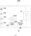
- the charging control circuit 1000 may include at least a detection circuit 101, a terminal control circuit 102, and a control device 103.
- the detection circuit 101 is capable of detecting at least whether the second interface 14 is connected to the second charging device 500.
- the terminal control circuit 102 can change at least the terminal state of the non-power terminal 13b.
- the control device 103 is configured to be capable of controlling the terminal control circuit 102 to operate to change the terminal state of the non-power terminal 13b.
- the change of the terminal state may be understood as a change of an object connected to an input terminal and/or output terminal of the power terminal 13a and/or the non-power terminal 13b in the charging control circuit 1000 or may be understood as a change of an electrical signal at the input terminal or output terminal of the power terminal 13a and/or the non-power terminal 13b.
- the detection circuit 101 and the control device 103 of the terminals may be disposed in one circuit.
- one element can detect whether the second interface 14 is connected to the second charging device 500 and control the terminal control circuit 102 to operate, that is, one element can implement the functions of the detection circuit 101 and the control device 103.
- the detection circuit 101 may determine whether the second interface 14 is connected to the second charging device 500 according to the change of the electrical signal at the second interface 14.
- a control chip identifies the communication data to determine whether the second interface 14 is connected to the second charging device 500.
- the control device 103 may determine whether the second interface 14 is connected to the second charging device 500 according to the electrical signal at the second interface 14 detected by the detection circuit 101.
- the control device 103 may control the terminal control circuit 102 to operate so that a terminal connection state of at least one non-power terminal 13b changes.
- one non-power terminal 13b may be changed from an original non-grounded state to a grounded state.
- the terminal control circuit 102 may include a thermistor 1021 and a controllable switch 1022 connected in parallel, where an end of the thermistor 1021 and the controllable switch 1022 connected in parallel is connected to a non-power terminal T, and the other end of the thermistor 1021 and the controllable switch 1022 connected in parallel is grounded.
- the control device 103 determines that the second interface 14 is connected to the second charging device 500, the control device 103 controls the controllable switch 1022 to be turned on so that the thermistor 1021 is shorted to ground and the non-power terminal T is grounded.
- the first charging device 400 connected to the first interface 13 can monitor the abnormal temperature at the non-power terminal T of the battery pack 100 so that over-temperature protection is performed to stop charging the battery pack 100 or not charge the battery pack 100. That is to say, when the second interface 14 is connected to the second charging device 500, the charging control circuit 1000 can change at least the connection state of the non-power terminal 13b so that the first charging device 400 connected to the first interface 13 can trigger one or more charging protection functions according to the connection state of the non-power terminal 13b, thereby preventing the battery pack 100 from being charged through the first charging device 400.
- the charging protection function triggered by the first charging device 400 according to the connection state of the non-power terminal 13b may include over-temperature protection, short-circuit protection, reverse connection protection, or low-voltage protection.
- the change of an interface state of the first interface 13 may cause the following: when the first charging device 400 is connected to the first interface 13, it is considered that the battery pack 100 may be overheated, or part of the circuit is accidentally short-circuited, or the charging interface of the first charging device 400 is reversely connected to the first interface 13, or the voltage of the battery pack 100 is too low to match the first charging device 400.
- the preceding problems cause the first charging device 400 to trigger charging protection and not charge the battery pack 100.
- the battery pack 100 in the present application may not have the preceding problems, and by changing the interface state of the first interface 13 or changing at least the terminal connection state of the non-power terminal 13b, the first charging device 400 mistakenly believes that the battery pack 10 has the preceding problems, and then the first charging device 400 triggers charging protection. In this manner, the battery pack 100 can be prevented from being charged through the first interface 13 and the second interface 14 at the same time.
- the charging control circuit 1000 can change at least the connection state of the non-power terminal 13b so that a battery management module in the battery pack 100 can trigger the charging protection function of the battery pack 100 or trigger at least the charging protection function of charging through the first interface 13.
- the battery pack 100 can change the interface state of the first interface 13 so that the power tool 200 connected to the first interface 13 triggers a discharging protection function. In this manner, the battery pack 100 cannot be discharged through the first interface 13 while being charged through the second interface 14.
- a power control circuit 1100 is disposed in the battery pack 100.
- the power control circuit 1100 can control at least the charge power and/or discharge power of the second interface 14.
- the power control circuit 1100 includes at least a power control module 1110 connected to the second interface 14.
- the power control module 1110 is used for changing the charge power and/or discharge power of the second interface 14 according to the temperature of the battery pack 100.
- the nominal voltage of the battery pack 100 is greater than 10 V.
- the nominal voltage of the battery pack 100 may be 12 V, and thus the nominal voltage of the first interface 13 may also be 12 V.
- the power control module 1110 includes an adjustment unit 1111, a management unit 1112, and a temperature detection unit 1113.
- An end of the adjustment unit 1111 is connected to the second interface 14, and the other end of the adjustment unit 1111 is connected to the multiple cells 12. That the power control module 1110 is connected to the second interface 14 is specifically that the adjustment unit 1111 in the power control module 1110 is connected to the second interface 14.
- An end of the management unit 1112 is connected to the adjustment unit 1111, and the other end of the management unit 1112 is connected to the temperature detection unit 1113.
- the temperature detection unit 1113 is used for detecting the temperature of the battery pack 100 and transmitting the detected temperature of the battery pack 100 to the management unit 1112.
- the management unit 1112 controls the adjustment unit 1111 based on the received temperature of the battery pack 100.
- the adjustment unit 1111 changes the power of the second interface 14 based on the control of the management unit 1112.
- the power may be the charge power when the second interface 14 is in a charging state or the discharge power when the second interface 14 is in a discharging state, which is not limited in the present application.
- the power control module 1110 includes the adjustment unit 1111 and a management module 1120.
- An end of the adjustment unit 1111 is connected to the second interface 14, and the other end of the adjustment unit 1111 is connected to the multiple cells 12.
- the management module 1120 is connected to the adjustment unit 1111.
- the management module 1120 includes the management unit 1112 and the temperature detection unit 1113.
- the temperature detection unit 1113 is used for detecting the temperature of the battery pack 100. That the management module 1120 controls the adjustment unit 1111 based on the temperature of the battery pack 100 is specifically that the management unit 1112 in the management module 1120 controls the adjustment unit 1111 based on the temperature of the battery pack 100.
- the temperature detection unit 1113 includes a first temperature detection unit 1113a and a second temperature detection unit 1113b, the first temperature detection unit 1113a is connected to the management unit 1112, and the second temperature detection unit 1113b is connected to the multiple cells 12.
- the first temperature detection unit 1113a is used for detecting the temperature of the power control module 1110
- the second temperature detection unit 1113b is used for detecting the temperature of the multiple cells 12.
- the temperature of the battery pack 100 detected by the temperature detection unit 1113 includes both the temperature of the power control module 1110 and the temperature of the cells 12.
- the temperature detection unit 1113 includes only the first temperature detection unit 1113a, then the temperature of the battery pack 100 detected by the temperature detection unit 1113 includes only the temperature of the power control module 1110.
- the temperature detection unit 1113 includes only the second temperature detection unit 1113b, then the temperature of the battery pack 100 detected by the temperature detection unit 1113 includes only the temperature of the cells 12.
- the second temperature detection unit 1113b may include, but is not limited to, a thermistor, which is not limited in the present application.
- the temperature of the battery pack 100 is determined by the magnitude of the current in the battery pack 100 and the time. For example, the larger the current value is and the longer the current is maintained, the higher the temperature of the battery pack 100 is. Therefore, in some examples, the temperature detection unit 1113 may be replaced by a current value and time detection unit. The function and connection manner of the current value and time detection unit are consistent with those of the temperature detection unit 1113, and the details are not repeated here.
- the adjustment unit 1111 may include a voltage control module 1111a and a current control module 1111b.
- the management unit 1112 controls the adjustment unit 1111 to change the charge power and/or discharge power of the second interface 14.
- the preset threshold includes a first preset threshold and a second preset threshold
- the first preset threshold is a temperature threshold of the power control module 1110
- the second preset threshold is a temperature threshold of the multiple cells 12.
- the first preset threshold is greater than the second preset threshold.
- the first preset threshold may be 100°C
- the second preset threshold may be 60°C
- the first preset threshold and the second preset threshold may also be any other values set according to empirical values and are not limited in the present application.
- the management unit 1112 needs to control the adjustment unit 1111.
- the voltage control module 1111a may reduce the voltage reaching the second interface 14 from the cells 12, and the current control module 1111b may reduce the current reaching the second interface 14 from the cells 12.
- the voltage control module 1111a may reduce the voltage reaching the second interface 14 from the cells 12 in a stepwise manner according to a fixed voltage value or not according to a fixed voltage value.
- the current control module 1111b may reduce the current reaching the second interface 14 from the cells 12 in a stepwise manner according to a fixed current value or not according to a fixed current value.
- the charge power and/or discharge power of the second interface 14 can be reduced so that the temperature of the battery pack 100 decreases, thereby avoiding the following: the battery pack 100 maintains a high temperature for a long time, causing safety hazards to the battery pack 100 and making the life of the battery pack 100 unguaranteed.
- the voltage control module 1111a and the current control module 1111b may perform the reduction operation at the same time so that the temperature of the battery pack 100 decreases rapidly; or only one of the two modules may perform the reduction operation, which is not limited in the present application. The specific selection may be made according to the temperature of the battery pack 100 exceeding the preset threshold.
- the discharge voltage of the second interface 14 is greater than or equal to 5 V and less than or equal to 20 V, that is, the output voltage range of the second interface 14 is 5 V to 20 V. Therefore, when the voltage control module 1111a reduces the voltage reaching the second interface 14 in the discharging state from the cells 12, the voltage reaching the second interface 14 is not less than 5 V.
- the adjustment unit 1111 may include only the voltage control module 1111a. In some examples, the adjustment unit 1111 may include only the current control module 1111b. The present application does not limit the control module specifically included in the adjustment unit 1111.
- the temperature detection unit 1113 When the temperature of the battery pack 100 detected by the temperature detection unit 1113 is less than the preset threshold and the power of the battery pack 100 is less than the maximum power, it means that the output power and/or input power of the second interface may be increased.
- the temperature detection unit 1113 includes both the first temperature detection unit 1113a and the second temperature detection unit 1113b, it is required that the temperature detected by the first temperature detection unit 1113a is less than the first preset threshold and the temperature detected by the second temperature detection unit 1113b is less than the second preset threshold.
- the management unit 1112 controls the adjustment unit 1111 to increase the charge power and/or discharge power of the second interface 14 so that while the safety and life of the battery pack 100 are ensured, the charging speed and/or discharging speed of the battery pack 100 can be increased, and the charging and discharging performance of the battery pack 100 can be improved.
- the adjustment unit 1111 includes the voltage control module 1111a and the current control module 1111b
- the voltage control module 1111a may increase the voltage reaching the second interface 14 from the cells 12
- the current control module 1111b may increase the current reaching the second interface 14 from the cells 12.
- the voltage control module 1111a may increase the voltage reaching the second interface 14 from the cells 12 in a stepwise manner according to a fixed voltage value or not according to a fixed voltage value.
- the current control module 1111b may increase the current reaching the second interface 14 from the cells 12 in a stepwise manner according to a fixed current value or not according to a fixed current value.
- the voltage control module 1111a and the current control module 1111b may perform the boost operation at the same time; or only one of the two modules may perform the boost operation, which is not limited in the present application. The specific selection may be made according to the power situation of the battery pack 100.
- the output voltage range of the second interface 14 is 5 V to 20 V, when the voltage control module 1111a increases the voltage reaching the second interface 14 in the discharging state from the cells 12, the voltage reaching the second interface 14 is not higher than 20 V.
- FIG. 9 proposes a control method for a battery pack.
- the control method for a battery pack includes the steps below.
- step 900 the battery pack 100 performs charging/discharging through the second interface 14.
- the battery pack 100 is in a state of being charged/discharged through the second interface 14.
- step 910 the temperature of the battery pack 100 is detected.
- step 900 When it is determined in step 900 that the battery pack 100 performs charging/discharging through the second interface 14, the temperature of the battery pack 100 is detected by the temperature detection unit 1113 described above in the present application.
- step 920 whether the temperature of the battery pack 100 reaches the preset threshold is determined.
- step 930A is performed; and when the temperature of the battery pack 100 is less than the preset threshold (that is, does not reach the preset threshold), step 930B is performed.
- step 930A the charge/discharge power of the second interface 14 is reduced.
- the management unit 1112 of the present application controls the adjustment unit 1111 to reduce the charge power and/or discharge power of the second interface 14. In this manner, the temperature of the battery pack 100 decreases, the probability of potential safety hazards of the battery pack 100 is reduced, and the safety and service life of the battery pack 100 are improved.
- step 930B whether the power of the battery pack 100 reaches the maximum power is determined.
- step 940 the charge/discharge power of the second interface 14 is increased.
- step 930B If it is determined in step 930B that the temperature of the battery pack 100 is less than the preset threshold and the power of the battery pack 100 has not reached the maximum power, specifically, the management unit 1112 controls the adjustment unit 1111 to increase the charge power and/or discharge power of the second interface 14, thereby increasing the charging/discharging speed of the battery pack 100.
- the rated charge power of the battery pack 100 may be set to be greater than the rated discharge power.
- the battery pack 100 further includes an indicator light for indicating the charge power and discharge power of the battery pack 100.
- the indicator light flashes at a larger frequency; and when the charge power and/or discharge power of the battery pack 100 is less than the preset power threshold, the indicator light flashes at a smaller frequency.
- the indicator light may include only one light. The indicator light is always on when the charge power and/or discharge power of the battery pack 100 is greater than or equal to the preset power threshold; and the indicator light is off when the charge power and/or discharge power of the battery pack 100 is less than the preset power threshold.
- the indicator light may include two lights which are a first indicator light and a second indicator light.
- the first indicator light is always on when the charge power and/or discharge power of the battery pack 100 is greater than or equal to the preset power threshold; and the second indicator light is always on when the charge power and/or discharge power of the battery pack 100 is less than the preset power threshold.
- the indicator light may include four lights arranged in the same row. The last indicator light is always on when the charge power and/or discharge power of the battery pack 100 is greater than or equal to the preset power threshold; and the four indicator lights light up one after another in sequence when the charge power and/or discharge power of the battery pack 100 is less than the preset power threshold.
- the indicator light may be in any other form in which whether the charge power and/or discharge power is greater than the preset power threshold can be displayed, which is not limited in the present application.
- the preset power threshold is determined according to empirical values.
Landscapes
- Engineering & Computer Science (AREA)
- Power Engineering (AREA)
- Chemical & Material Sciences (AREA)
- Chemical Kinetics & Catalysis (AREA)
- Electrochemistry (AREA)
- General Chemical & Material Sciences (AREA)
- Manufacturing & Machinery (AREA)
- Microelectronics & Electronic Packaging (AREA)
- Charge And Discharge Circuits For Batteries Or The Like (AREA)
Abstract
Provided is a battery pack configured to be capable of supplying power to a power tool. The battery pack includes a housing assembly; multiple cells disposed in the housing assembly; a first interface configured to be connectable to a first charging device and configured to be capable of supplying power to the power tool; a second interface configured to be connectable to a second charging device; and a power control module configured to be connected to the second interface. The power control module is used for changing the charge power and/or discharge power of the second interface according to the temperature of the battery pack. The preceding technical solution is adopted so that a safer battery pack with a longer service life for a power tool can be provided.
Description
- The present application relates to an energy storage device and, in particular, to a battery pack configured to be capable of supplying power to a power tool.
- A portable power tool is applicable in various scenarios of production and life. A rechargeable battery pack is configured to power the power tool so that the power tool is free from wires and more convenient for a user to use. Generally, an external charging/discharging interface terminal on the battery pack can be connected to a power interface of the power tool and can also be connected to a charging port of a battery pack charger. With the development of battery pack technologies, the design of a Type-C interface on the battery pack for the power tool has gradually become a new development trend. In this manner, the battery pack for the power tool can supply power to a mobile terminal or other electrical devices with Type-C interfaces and can be charged using a Type-C charger, providing more room for the development of the battery pack.
- This part provides background information related to the present application, and the background information is not necessarily the existing art.
- To solve the deficiencies in the existing art, an object of the present application is to provide a safer battery pack with a longer service life for a power tool.
- To achieve the preceding object, the present application adopts the technical solutions below.
- A battery pack configured to be capable of supplying power to a power tool includes a housing assembly; multiple cells disposed in the housing assembly; a first interface configured to be connectable to a first charging device and configured to be capable of supplying power to the power tool; a second interface configured to be connectable to a second charging device; and a power control module configured to be connected to the second interface. The power control module is used for changing the charge power and/or discharge power of the second interface according to the temperature of the battery pack.
- In some examples, the second interface is a Type-C interface.
- In some examples, the power control module includes a temperature detection unit for detecting the temperature of the battery pack.
- In some examples, the temperature detection unit includes a first temperature detection unit and/or a second temperature detection unit, where the first temperature detection unit is used for detecting the temperature of the power control module in the battery pack, and the second temperature detection unit is used for detecting the temperature of the multiple cells in the battery pack.
- In some examples, the second temperature detection unit is a thermistor.
- In some examples, the power control module further includes a management unit and an adjustment unit, where the adjustment unit is connected to the multiple cells, the management unit is connected to the adjustment unit and the temperature detection unit, and the management unit controls the adjustment unit based on the temperature detected by the temperature detection unit and a preset threshold.
- In some examples, the adjustment unit includes a voltage control module used for, when the temperature of the battery pack is greater than or equal to the preset threshold, reducing the voltage reaching the second interface.
- In some examples, the adjustment unit includes a current control module used for, when the temperature of the battery pack is greater than or equal to the preset threshold, reducing the current reaching the second interface.
- In some examples, the adjustment unit includes a voltage control module and a current control module, where when the temperature of the battery pack is greater than or equal to the preset threshold, the voltage control module reduces the voltage reaching the second interface, and the current control module reduces the current reaching the second interface.
- In some examples, when the temperature of the battery pack is less than the preset threshold and the power of the battery pack is less than the maximum power, the management unit controls the adjustment unit to increase the output power and/or input power of the second interface.
- In some examples, the preset threshold includes a first preset threshold and a second preset threshold, the first preset threshold is a temperature threshold of the power control module in the battery pack, and the second preset threshold is a temperature threshold of the multiple cells in the battery pack, where the first preset threshold is greater than the second preset threshold.
- In some examples, the power control module includes a current value and time detection unit for detecting a current value of the battery pack and the time during which the current value is maintained.
- In some examples, the nominal voltage of the first interface is greater than 10 V, and the discharge voltage of the second interface is greater than or equal to 5 V and less than or equal to 20 V.
- In some examples, the battery pack includes an indicator light for indicating the charge power and/or discharge power of the battery pack.
- In some examples, the indicator light performs an indication based on a relationship between the charge power and/or discharge power of the battery pack and a preset power threshold.
- In some examples, a battery pack configured to be capable of supplying power to a power tool includes a housing assembly; multiple cells disposed in the housing assembly; a first interface configured to be connectable to a first charging device and configured to be capable of supplying power to the power tool; a second interface configured to be connectable to a second charging device; and a power control module configured to be connected to the second interface. The power control module is used for changing the charge power and/or discharge power of the second interface according to a parameter of the battery pack.
- In some examples, the second interface is a Type-C interface.
- In some examples, a battery pack configured to be capable of supplying power to a power tool includes a housing assembly; multiple cells disposed in the housing assembly; a first interface configured to be connectable to a first charging device and configured to be capable of supplying power to the power tool; a second interface configured to be connectable to a second charging device; and a power control module configured to be connected to the second interface. The power control module controls the charge power and/or discharge power of the second interface so that a parameter of the battery pack is less than a preset threshold.
- In some examples, the second interface is a Type-C interface.
- In some examples, after the parameter of the battery pack reaches the preset threshold, the power control module reduces the charge power and/or discharge power of the second interface.
- The benefit of the present application lies in that by changing the charge/discharge power of the second interface based on the temperature of the battery pack, the following problem is solved: the battery pack is in a high temperature state for a long time, bringing in certain dangers; and the safety and life of the battery pack are improved.
-
-
FIG. 1 is a schematic view of a power supply system of a battery pack according to an example. -
FIG. 2 is a schematic view of a charging system of a battery pack according to an example. -
FIG. 3 is a schematic diagram of an internal charging control circuit of a battery pack according to an example. -
FIG. 4 is a schematic diagram of an internal charging control circuit of a battery pack according to an example. -
FIG. 5 is a schematic diagram of a power control circuit of a battery pack according to an example. -
FIG. 6 is a schematic diagram of another power control circuit of a battery pack according to an example. -
FIG. 7 is a schematic diagram of a temperature detection unit of a battery pack according to an example. -
FIG. 8 is a schematic diagram of an adjustment unit of a battery pack according to an example. -
FIG. 9 is a flowchart of a control method for a battery pack according to an example. - Before any example of the present application is explained in detail, it is to be understood that the present application is not limited to its application to the structural details and the arrangement of components set forth in the following description or illustrated in the preceding drawings.
- In the present application, the term "comprising", "including", "having", or any other variant thereof is intended to encompass a non-exclusive inclusion so that a process, method, article, or device that includes a series of elements not only includes those elements but also includes other elements that are not expressly listed or further includes elements that are inherent to such a process, method, article, or device. In the absence of more limitations, an element defined by the statement "including a ..." does not exclude the presence of additional identical elements in a process, method, article, or device including the element.
- In the present application, the term "and/or" is an association relationship describing associated objects and indicates that three relationships may exist. For example, A and/or B may indicate that A exists alone, both A and B exist, and B exists alone. In addition, in the present application, the character "/" generally indicates an "and/or" relationship between associated objects before and after the character "/".
- In the present application, the term "connected", "combined", "coupled", or "mounted" may be directly "connected", "combined", "coupled", or "mounted" and may also be indirectly "connected", "combined", "coupled", or "mounted". Among them, for example, direct connection means that two parts or assemblies are connected together without intermediate pieces, and indirect connection means that two parts or assemblies are separately connected to at least one intermediate piece and the two parts or assemblies are connected to each other by the at least one intermediate piece. Furthermore, "connected" and "coupled" are not limited to physical or mechanical connections or couplings and may include electrical connections or couplings.
- In the present application, it is to be understood by those of ordinary skill in the art that a relative term (for example, "about", "approximately", or "basically") used in conjunction with quantities or conditions is inclusive of the stated value and has the meaning indicated by the context. For example, the relative term includes at least a degree of error associated with the measurement of a particular value, a tolerance caused by manufacturing, assembly, and use associated with the particular value, and the like. Such relative term should also be considered as disclosing the range defined by the absolute values of the two endpoints. The relative term may refer to plus or minus a certain percentage (such as 1%, 5%, 10%, or more) of an indicated value. A value not modified by the relative term should also be disclosed as a particular value with a tolerance. In addition, when expressing a relative angular position relationship (for example, basically parallel or basically perpendicular), "basically" may refer to plus or minus a certain degree (such as 1 degree, 5 degrees, 10 degrees, or more) based on an indicated angle.
- In the present application, it is to be understood by those of ordinary skill in the art that the function implemented by an assembly may be implemented by one assembly, multiple assemblies, one part, or multiple parts. Similarly, a function implemented by a part may be implemented by one part, one assembly, or a combination of parts.
- In the present application, the terms "upper", "lower", "left", "right", "front", "rear", and other orientation words are described by the orientations and position relations shown in the drawings and should not be understood as a limitation to the examples of the present application. In addition, in this context, it also needs to be understood that when it is mentioned that an element is connected "above" or "below" another element, the element not only can be directly connected "above" or "below" the other element but also can be indirectly connected "above" or "below" the other element through an intermediate element. Further, it should be understood that orientation words such as the upper side, lower side, left side, right side, front side, and rear side not only represent perfect orientations but also may be understood as lateral orientations. For example, the lower part may include directly below, lower left, lower right, lower front, and lower back.
- In the present application, the terms "controller", "processor", "central processing unit", "CPU", and "MCU" are interchangeable. Where a unit such as the "controller", the "processor", the "central processing unit", the "CPU", or the "MCU" is used to implement specific functions, these functions may be implemented by a single one of the preceding units or multiple preceding units unless otherwise indicated.
- In the present application, the term "device", "module", or "unit" is used to implement a specific function in the form of hardware or software.
- In the present application, the terms "computing", "judging", "controlling", "determining", "identifying", and the like refer to the operation and processes of a computer system or similar electronic computing device (for example, the controller, the processor, or the like).
- In this example, various power tools 200 can be powered by a
battery pack 100.FIG. 1 illustrates several common power tools, such as anelectric drill 200a, achainsaw 200b, astring trimmer 200c, and ablower 200d. It is to be noted that the power tool 200 may be a handheld power tool, such as a drill, a hedge trimmer, or a sander. Alternatively, the power tool 200 may be a table tool, such as a table saw or a miter saw. Alternatively, the power tool 200 may be a push power tool, such as a push mower or a push snow thrower. Alternatively, the power tool 200 may be a riding power tool, such as a riding mower, a riding vehicle, or an all-terrain vehicle. Alternatively, the power tool 200 may be a robotic tool, such as a robotic mower or a robotic snow thrower. In some examples, the power tool 200 may be an electric drill, an electric lamp, an electric vehicle, or the like. In some examples, the power tool 200 may be a garden tool, such as a hedge trimmer, a blower, a mower, or a chainsaw. Alternatively, the power tool 200 may be a decorating tool, such as a screwdriver, a nail gun, a circular saw, or a sander. In some examples, the power tool 200 may be a vegetation care tool, such as a string trimmer, a mower, a hedge trimmer, or a chainsaw. Alternatively, the power tool 200 may be a cleaning tool, such as a blower, a snow thrower, or a washer. Alternatively, the power tool 200 may be a drilling tool, such as a drill, a screwdriver, a wrench, or an electric hammer. Alternatively, the power tool 200 may be a sawing tool, such as a reciprocating saw, a jigsaw, or a circular saw. Alternatively, the power tool 200 may be a table tool, such as a table saw, a miter saw, a metal cutter, or an electric router. Alternatively, the power tool 200 may be a sanding tool, such as an angle grinder or a sander. - In this example, various electrical devices 300 may be powered by the
battery pack 100. The electrical devices may be other household appliances or personal electrical devices in addition to the preceding power tools 200, such as asmartphone 300a, alaptop 300b, and amobile power supply 300c inFIG. 1 , or the electrical devices may be a soy milk maker, a grinder, and the like. - The
battery pack 100 shown inFIG. 2 may include ahousing assembly 11,multiple cells 12 accommodated in thehousing assembly 11, and afirst interface 13 and asecond interface 14 formed on thehousing assembly 11. Thehousing assembly 11 may include anupper housing 111 and alower housing 112. Themultiple cells 12 accommodated in thehousing assembly 11 may be connected in various manners, such as connection in series, connection in parallel, or a combination of connection in series and connection in parallel. This example does not limit the connection manners of thecells 12. - Referring to
FIGS. 2 and3 , thefirst interface 13 may be connected to afirst charging device 400 so that thecells 12 in thebattery pack 100 are charged. In this example, thefirst interface 13 may include at least apositive connection terminal 131 and anegative connection terminal 132 or may further include acommunication terminal 133, and thepositive connection terminal 131, thenegative connection terminal 132, and thecommunication terminal 133 can be directly coupled to charging terminals on thefirst charging device 400. In this example, thefirst interface 13 may be directly coupled to a power interface on the power tool 200 so that the power tool 200 is powered. In this example, thefirst interface 13 may further includepower terminals 13a and anon-power terminal 13b. The so-calledpower terminals 13a may be the precedingpositive connection terminal 131 and the precedingnegative connection terminal 132, and thenon-power terminal 13b may be thecommunication terminal 133 and may further include a temperature detection terminal T or an ID identification terminal B. - The
second interface 14 may be a Type-C interface and is connectable to asecond charging device 500 so that thecells 12 in thebattery pack 100 are charged. Further, thesecond interface 14 is connectable to the electrical device 300 with a Type-C interface so that the electrical device 300 is powered. - In an example, the
second charging device 500 may be a charger for a mobile phone or a computer. - In an example, the
first interface 13 and thesecond interface 14 can work simultaneously. For example, thebattery pack 100 may be charged through thefirst interface 13 and discharged through thesecond interface 14 at the same time; or thebattery pack 100 may be discharged through thefirst interface 13 and charged through thesecond interface 14 at the same time; or thebattery pack 100 may be charged through thefirst interface 13 and charged through thesecond interface 14 at the same time. In some examples, thebattery pack 100 may be discharged through thefirst interface 13 and discharged through thesecond interface 14 at the same time. However, in fact, when charging is performed through the two interfaces at the same time, thebattery pack 100 has certain safety risks. For example, the charging systems of the two interfaces are independent of each other; when the cells are charged through the two interfaces at the same time, the current may exceed the maximum allowable charge current of the cells, affecting the safety of the cells. - To avoid the case where charging is performed through the two interfaces at the same time, at least the charging state of the
first interface 13 may be controlled. For example, whether charging is performed through thefirst interface 13 is controlled according to the charging situation of thesecond interface 14. In fact, after thesecond interface 14 of thebattery pack 100 is connected to thesecond charging device 500, thefirst interface 13 may be controlled such that charging cannot be performed through thefirst interface 13, or thefirst interface 13 is controlled to be in a non-charging state. Thefirst interface 13 being in the non-charging state may be understood as that the charging circuit in thebattery pack 100 cannot obtain charging electrical energy through thefirst interface 13 or may be understood as that thefirst charging device 400 connected to thefirst interface 13 cannot charge thebattery pack 100. - Referring to
FIG. 3 , a chargingcontrol circuit 1000 is disposed in thebattery pack 100. The chargingcontrol circuit 1000 can control at least the charging state of thefirst interface 13. In this example, the chargingcontrol circuit 1000 may include at least adetection circuit 101, aterminal control circuit 102, and acontrol device 103. Thedetection circuit 101 is capable of detecting at least whether thesecond interface 14 is connected to thesecond charging device 500. Theterminal control circuit 102 can change at least the terminal state of thenon-power terminal 13b. Thecontrol device 103 is configured to be capable of controlling theterminal control circuit 102 to operate to change the terminal state of thenon-power terminal 13b. It is to be noted that the change of the terminal state may be understood as a change of an object connected to an input terminal and/or output terminal of thepower terminal 13a and/or thenon-power terminal 13b in the chargingcontrol circuit 1000 or may be understood as a change of an electrical signal at the input terminal or output terminal of thepower terminal 13a and/or thenon-power terminal 13b. - In some examples, in the charging
control circuit 1000, thedetection circuit 101 and thecontrol device 103 of the terminals may be disposed in one circuit. Alternatively, one element can detect whether thesecond interface 14 is connected to thesecond charging device 500 and control theterminal control circuit 102 to operate, that is, one element can implement the functions of thedetection circuit 101 and thecontrol device 103. - In this example, the
detection circuit 101 may determine whether thesecond interface 14 is connected to thesecond charging device 500 according to the change of the electrical signal at thesecond interface 14. Alternatively, a control chip identifies the communication data to determine whether thesecond interface 14 is connected to thesecond charging device 500. - In this example, the
control device 103 may determine whether thesecond interface 14 is connected to thesecond charging device 500 according to the electrical signal at thesecond interface 14 detected by thedetection circuit 101. When thecontrol device 103 determines that thesecond interface 14 is connected to thesecond charging device 500, thecontrol device 103 may control theterminal control circuit 102 to operate so that a terminal connection state of at least onenon-power terminal 13b changes. For example, onenon-power terminal 13b may be changed from an original non-grounded state to a grounded state. InFIG. 4 , theterminal control circuit 102 may include athermistor 1021 and acontrollable switch 1022 connected in parallel, where an end of thethermistor 1021 and thecontrollable switch 1022 connected in parallel is connected to a non-power terminal T, and the other end of thethermistor 1021 and thecontrollable switch 1022 connected in parallel is grounded. When thecontrol device 103 determines that thesecond interface 14 is connected to thesecond charging device 500, thecontrol device 103 controls thecontrollable switch 1022 to be turned on so that thethermistor 1021 is shorted to ground and the non-power terminal T is grounded. After thethermistor terminal 1021 is shorted to ground, thefirst charging device 400 connected to thefirst interface 13 can monitor the abnormal temperature at the non-power terminal T of thebattery pack 100 so that over-temperature protection is performed to stop charging thebattery pack 100 or not charge thebattery pack 100. That is to say, when thesecond interface 14 is connected to thesecond charging device 500, the chargingcontrol circuit 1000 can change at least the connection state of thenon-power terminal 13b so that thefirst charging device 400 connected to thefirst interface 13 can trigger one or more charging protection functions according to the connection state of thenon-power terminal 13b, thereby preventing thebattery pack 100 from being charged through thefirst charging device 400. The charging protection function triggered by thefirst charging device 400 according to the connection state of thenon-power terminal 13b may include over-temperature protection, short-circuit protection, reverse connection protection, or low-voltage protection. - In this example, the change of an interface state of the
first interface 13 may cause the following: when thefirst charging device 400 is connected to thefirst interface 13, it is considered that thebattery pack 100 may be overheated, or part of the circuit is accidentally short-circuited, or the charging interface of thefirst charging device 400 is reversely connected to thefirst interface 13, or the voltage of thebattery pack 100 is too low to match thefirst charging device 400. The preceding problems cause thefirst charging device 400 to trigger charging protection and not charge thebattery pack 100. In fact, thebattery pack 100 in the present application may not have the preceding problems, and by changing the interface state of thefirst interface 13 or changing at least the terminal connection state of thenon-power terminal 13b, thefirst charging device 400 mistakenly believes that the battery pack 10 has the preceding problems, and then thefirst charging device 400 triggers charging protection. In this manner, thebattery pack 100 can be prevented from being charged through thefirst interface 13 and thesecond interface 14 at the same time. - In some examples, when the
second interface 14 is connected to thesecond charging device 500, the chargingcontrol circuit 1000 can change at least the connection state of thenon-power terminal 13b so that a battery management module in thebattery pack 100 can trigger the charging protection function of thebattery pack 100 or trigger at least the charging protection function of charging through thefirst interface 13. - In other examples, the
battery pack 100 can change the interface state of thefirst interface 13 so that the power tool 200 connected to thefirst interface 13 triggers a discharging protection function. In this manner, thebattery pack 100 cannot be discharged through thefirst interface 13 while being charged through thesecond interface 14. - Referring to
FIG. 5 , apower control circuit 1100 is disposed in thebattery pack 100. Thepower control circuit 1100 can control at least the charge power and/or discharge power of thesecond interface 14. In this example, thepower control circuit 1100 includes at least apower control module 1110 connected to thesecond interface 14. Thepower control module 1110 is used for changing the charge power and/or discharge power of thesecond interface 14 according to the temperature of thebattery pack 100. The nominal voltage of thebattery pack 100 is greater than 10 V. For example, the nominal voltage of thebattery pack 100 may be 12 V, and thus the nominal voltage of thefirst interface 13 may also be 12 V. - As shown in
FIG. 5 , in some examples, thepower control module 1110 includes anadjustment unit 1111, amanagement unit 1112, and atemperature detection unit 1113. An end of theadjustment unit 1111 is connected to thesecond interface 14, and the other end of theadjustment unit 1111 is connected to themultiple cells 12. That thepower control module 1110 is connected to thesecond interface 14 is specifically that theadjustment unit 1111 in thepower control module 1110 is connected to thesecond interface 14. An end of themanagement unit 1112 is connected to theadjustment unit 1111, and the other end of themanagement unit 1112 is connected to thetemperature detection unit 1113. Thetemperature detection unit 1113 is used for detecting the temperature of thebattery pack 100 and transmitting the detected temperature of thebattery pack 100 to themanagement unit 1112. Themanagement unit 1112 controls theadjustment unit 1111 based on the received temperature of thebattery pack 100. Theadjustment unit 1111 changes the power of thesecond interface 14 based on the control of themanagement unit 1112. The power may be the charge power when thesecond interface 14 is in a charging state or the discharge power when thesecond interface 14 is in a discharging state, which is not limited in the present application. - As shown in
FIG. 6 , in some examples, thepower control module 1110 includes theadjustment unit 1111 and amanagement module 1120. An end of theadjustment unit 1111 is connected to thesecond interface 14, and the other end of theadjustment unit 1111 is connected to themultiple cells 12. Themanagement module 1120 is connected to theadjustment unit 1111. Themanagement module 1120 includes themanagement unit 1112 and thetemperature detection unit 1113. Thetemperature detection unit 1113 is used for detecting the temperature of thebattery pack 100. That themanagement module 1120 controls theadjustment unit 1111 based on the temperature of thebattery pack 100 is specifically that themanagement unit 1112 in themanagement module 1120 controls theadjustment unit 1111 based on the temperature of thebattery pack 100. - As shown in
FIG. 7 , in some examples, thetemperature detection unit 1113 includes a firsttemperature detection unit 1113a and a secondtemperature detection unit 1113b, the firsttemperature detection unit 1113a is connected to themanagement unit 1112, and the secondtemperature detection unit 1113b is connected to themultiple cells 12. The firsttemperature detection unit 1113a is used for detecting the temperature of thepower control module 1110, and the secondtemperature detection unit 1113b is used for detecting the temperature of themultiple cells 12. In this case, the temperature of thebattery pack 100 detected by thetemperature detection unit 1113 includes both the temperature of thepower control module 1110 and the temperature of thecells 12. Optionally, if thetemperature detection unit 1113 includes only the firsttemperature detection unit 1113a, then the temperature of thebattery pack 100 detected by thetemperature detection unit 1113 includes only the temperature of thepower control module 1110. Optionally, if thetemperature detection unit 1113 includes only the secondtemperature detection unit 1113b, then the temperature of thebattery pack 100 detected by thetemperature detection unit 1113 includes only the temperature of thecells 12. The secondtemperature detection unit 1113b may include, but is not limited to, a thermistor, which is not limited in the present application. - The temperature of the
battery pack 100 is determined by the magnitude of the current in thebattery pack 100 and the time. For example, the larger the current value is and the longer the current is maintained, the higher the temperature of thebattery pack 100 is. Therefore, in some examples, thetemperature detection unit 1113 may be replaced by a current value and time detection unit. The function and connection manner of the current value and time detection unit are consistent with those of thetemperature detection unit 1113, and the details are not repeated here. - As shown in
FIG. 8 , in some examples, theadjustment unit 1111 may include avoltage control module 1111a and acurrent control module 1111b. When the temperature of thebattery pack 100 detected by thetemperature detection unit 1113 is greater than or equal to a preset threshold, themanagement unit 1112 controls theadjustment unit 1111 to change the charge power and/or discharge power of thesecond interface 14. When thetemperature detection unit 1113 includes both the firsttemperature detection unit 1113a and the secondtemperature detection unit 1113b, the preset threshold includes a first preset threshold and a second preset threshold, the first preset threshold is a temperature threshold of thepower control module 1110, and the second preset threshold is a temperature threshold of themultiple cells 12. Since themultiple cells 12 are more sensitive to temperature and more affected at high temperatures than thepower control module 1110, the first preset threshold is greater than the second preset threshold. The first preset threshold may be 100°C, the second preset threshold may be 60°C, and the first preset threshold and the second preset threshold may also be any other values set according to empirical values and are not limited in the present application. In this case, when the temperature detected by the firsttemperature detection unit 1113a is greater than or equal to the first preset threshold or the temperature detected by the secondtemperature detection unit 1113b is greater than or equal to the second preset threshold, themanagement unit 1112 needs to control theadjustment unit 1111. Specifically, thevoltage control module 1111a may reduce the voltage reaching thesecond interface 14 from thecells 12, and thecurrent control module 1111b may reduce the current reaching thesecond interface 14 from thecells 12. Thevoltage control module 1111a may reduce the voltage reaching thesecond interface 14 from thecells 12 in a stepwise manner according to a fixed voltage value or not according to a fixed voltage value. Similarly, thecurrent control module 1111b may reduce the current reaching thesecond interface 14 from thecells 12 in a stepwise manner according to a fixed current value or not according to a fixed current value. In this manner, the charge power and/or discharge power of thesecond interface 14 can be reduced so that the temperature of thebattery pack 100 decreases, thereby avoiding the following: thebattery pack 100 maintains a high temperature for a long time, causing safety hazards to thebattery pack 100 and making the life of thebattery pack 100 unguaranteed. Thevoltage control module 1111a and thecurrent control module 1111b may perform the reduction operation at the same time so that the temperature of thebattery pack 100 decreases rapidly; or only one of the two modules may perform the reduction operation, which is not limited in the present application. The specific selection may be made according to the temperature of thebattery pack 100 exceeding the preset threshold. - The discharge voltage of the
second interface 14 is greater than or equal to 5 V and less than or equal to 20 V, that is, the output voltage range of thesecond interface 14 is 5 V to 20 V. Therefore, when thevoltage control module 1111a reduces the voltage reaching thesecond interface 14 in the discharging state from thecells 12, the voltage reaching thesecond interface 14 is not less than 5 V. - In some examples, the
adjustment unit 1111 may include only thevoltage control module 1111a. In some examples, theadjustment unit 1111 may include only thecurrent control module 1111b. The present application does not limit the control module specifically included in theadjustment unit 1111. - When the temperature of the
battery pack 100 detected by thetemperature detection unit 1113 is less than the preset threshold and the power of thebattery pack 100 is less than the maximum power, it means that the output power and/or input power of the second interface may be increased. When thetemperature detection unit 1113 includes both the firsttemperature detection unit 1113a and the secondtemperature detection unit 1113b, it is required that the temperature detected by the firsttemperature detection unit 1113a is less than the first preset threshold and the temperature detected by the secondtemperature detection unit 1113b is less than the second preset threshold. In this manner, themanagement unit 1112 controls theadjustment unit 1111 to increase the charge power and/or discharge power of thesecond interface 14 so that while the safety and life of thebattery pack 100 are ensured, the charging speed and/or discharging speed of thebattery pack 100 can be increased, and the charging and discharging performance of thebattery pack 100 can be improved. Optionally, when theadjustment unit 1111 includes thevoltage control module 1111a and thecurrent control module 1111b, thevoltage control module 1111a may increase the voltage reaching thesecond interface 14 from thecells 12, and thecurrent control module 1111b may increase the current reaching thesecond interface 14 from thecells 12. Thevoltage control module 1111a may increase the voltage reaching thesecond interface 14 from thecells 12 in a stepwise manner according to a fixed voltage value or not according to a fixed voltage value. Similarly, thecurrent control module 1111b may increase the current reaching thesecond interface 14 from thecells 12 in a stepwise manner according to a fixed current value or not according to a fixed current value. Thevoltage control module 1111a and thecurrent control module 1111b may perform the boost operation at the same time; or only one of the two modules may perform the boost operation, which is not limited in the present application. The specific selection may be made according to the power situation of thebattery pack 100. In addition, since the output voltage range of thesecond interface 14 is 5 V to 20 V, when thevoltage control module 1111a increases the voltage reaching thesecond interface 14 in the discharging state from thecells 12, the voltage reaching thesecond interface 14 is not higher than 20 V. - In addition, when the temperature of the
battery pack 100 detected by thetemperature detection unit 1113 is less than the preset threshold and the power of thebattery pack 100 has reached the maximum power, no operation is performed on thebattery pack 100 at this time. -
FIG. 9 proposes a control method for a battery pack. The control method for a battery pack includes the steps below. - In
step 900, thebattery pack 100 performs charging/discharging through thesecond interface 14. - The
battery pack 100 is in a state of being charged/discharged through thesecond interface 14. - In
step 910, the temperature of thebattery pack 100 is detected. - When it is determined in
step 900 that thebattery pack 100 performs charging/discharging through thesecond interface 14, the temperature of thebattery pack 100 is detected by thetemperature detection unit 1113 described above in the present application. - In
step 920, whether the temperature of thebattery pack 100 reaches the preset threshold is determined. - After the temperature of the
battery pack 100 is detected instep 910, when the temperature of thebattery pack 100 is greater than or equal to the preset threshold (that is, reaches the preset threshold),step 930A is performed; and when the temperature of thebattery pack 100 is less than the preset threshold (that is, does not reach the preset threshold),step 930B is performed. - In
step 930A, the charge/discharge power of thesecond interface 14 is reduced. - After the temperature of the
battery pack 100 is greater than or equal to the preset threshold, specifically, themanagement unit 1112 of the present application controls theadjustment unit 1111 to reduce the charge power and/or discharge power of thesecond interface 14. In this manner, the temperature of thebattery pack 100 decreases, the probability of potential safety hazards of thebattery pack 100 is reduced, and the safety and service life of thebattery pack 100 are improved. - In
step 930B, whether the power of thebattery pack 100 reaches the maximum power is determined. - After it is determined that the temperature of the
battery pack 100 is less than the preset threshold, when the power of thebattery pack 100 reaches the maximum power, although the temperature of thebattery pack 100 is less than the preset threshold, no operation is performed on thebattery pack 100. When the power of thebattery pack 100 has not reached the maximum power and the temperature of thebattery pack 100 is less than the preset threshold,step 940 is performed. - In
step 940, the charge/discharge power of thesecond interface 14 is increased. - If it is determined in
step 930B that the temperature of thebattery pack 100 is less than the preset threshold and the power of thebattery pack 100 has not reached the maximum power, specifically, themanagement unit 1112 controls theadjustment unit 1111 to increase the charge power and/or discharge power of thesecond interface 14, thereby increasing the charging/discharging speed of thebattery pack 100. - In some examples, since the temperature of the
battery pack 100 rises more during discharging than during charging, when thebattery pack 100 leaves the factory, the rated charge power of thebattery pack 100 may be set to be greater than the rated discharge power. - In some examples, the
battery pack 100 further includes an indicator light for indicating the charge power and discharge power of thebattery pack 100. Optionally, when the charge power and/or discharge power of thebattery pack 100 is greater than or equal to a preset power threshold, the indicator light flashes at a larger frequency; and when the charge power and/or discharge power of thebattery pack 100 is less than the preset power threshold, the indicator light flashes at a smaller frequency. Optionally, the indicator light may include only one light. The indicator light is always on when the charge power and/or discharge power of thebattery pack 100 is greater than or equal to the preset power threshold; and the indicator light is off when the charge power and/or discharge power of thebattery pack 100 is less than the preset power threshold. Optionally, the indicator light may include two lights which are a first indicator light and a second indicator light. The first indicator light is always on when the charge power and/or discharge power of thebattery pack 100 is greater than or equal to the preset power threshold; and the second indicator light is always on when the charge power and/or discharge power of thebattery pack 100 is less than the preset power threshold. Optionally, the indicator light may include four lights arranged in the same row. The last indicator light is always on when the charge power and/or discharge power of thebattery pack 100 is greater than or equal to the preset power threshold; and the four indicator lights light up one after another in sequence when the charge power and/or discharge power of thebattery pack 100 is less than the preset power threshold. In addition, the indicator light may be in any other form in which whether the charge power and/or discharge power is greater than the preset power threshold can be displayed, which is not limited in the present application. The preset power threshold is determined according to empirical values. - The basic principles, main features, and advantages of the present application are shown and described above. It is to be understood by those skilled in the art that the preceding examples do not limit the present application in any form, and all technical solutions obtained through equivalent substitutions or equivalent transformations fall within the scope of the present application.
Claims (15)
- A battery pack (100) configured to be capable of supplying power to a power tool (200), comprising:a housing assembly (11);a plurality of cells (12) disposed in the housing assembly;a first interface (13) configured to be connectable to a first charging device (400) and configured to be capable of supplying power to the power tool;a second interface (14) configured to be connectable to a second charging device (500); anda power control module (1110) configured to be connected to the second interface;wherein the power control module is configured to change charge power and/or discharge power of the second interface according to temperature of the battery pack.
- The battery pack of claim 1, wherein the second interface is a Type-C interface.
- The battery pack of claim 1, wherein the power control module comprises a temperature detection unit (1113) for detecting the temperature of the battery pack.
- The battery pack of claim 3, wherein the temperature detection unit comprises a first temperature detection unit (1113a) and/or a second temperature detection unit (1113b), the first temperature detection unit is configured to detect temperature of the power control module in the battery pack, and the second temperature detection unit is configured to detect temperature of the plurality of cells in the battery pack.
- The battery pack of claim 4, wherein the second temperature detection unit is a therm istor.
- The battery pack of claim 3, wherein the power control module further comprises a management unit (1112) and an adjustment unit (1111), the adjustment unit is connected to the plurality of cells, the management unit is connected to the adjustment unit and the temperature detection unit, and the management unit controls the adjustment unit based on the temperature detected by the temperature detection unit and a preset threshold.
- The battery pack of claim 6, wherein the adjustment unit comprises a voltage control module (1111a) used for, when the temperature of the battery pack is greater than or equal to the preset threshold, reducing a voltage reaching the second interface.
- The battery pack of claim 6, wherein the adjustment unit comprises a current control module (1111b) used for, when the temperature of the battery pack is greater than or equal to the preset threshold, reducing a current reaching the second interface.
- The battery pack of claim 6, wherein the adjustment unit comprises a voltage control module (1111a) and a current control module(1111b), and the voltage control module reduces a voltage reaching the second interface and the current control module reduces a current reaching the second interface when the temperature of the battery pack is greater than or equal to the preset threshold.
- The battery pack of claim 6, wherein when the temperature of the battery pack is less than the preset threshold and power of the battery pack is less than maximum power, the management unit controls the adjustment unit to increase output power and/or input power of the second interface.
- The battery pack of claim 6, wherein the preset threshold comprises a first preset threshold and a second preset threshold, the first preset threshold is a temperature threshold of the power control module in the battery pack, the second preset threshold is a temperature threshold of the plurality of cells in the battery pack, and the first preset threshold is greater than the second preset threshold.
- The battery pack of claim 1, wherein the power control module comprises a detection unit for detecting a current value of the battery pack and time during which the current value is maintained.
- The battery pack of claim 1, wherein a nominal voltage of the first interface is greater than 10 V, and a discharge voltage of the second interface is greater than or equal to 5 V and less than or equal to 20 V.
- The battery pack of claim 1, further comprising an indicator light for indicating the charge power and/or discharge power of the battery pack.
- The battery pack of claim 14, wherein the indicator light performs an indication based on a relationship between the charge power and/or discharge power of the battery pack and a preset power threshold.
Applications Claiming Priority (1)
| Application Number | Priority Date | Filing Date | Title |
|---|---|---|---|
| CN202311378696.7A CN119921048A (en) | 2023-10-23 | 2023-10-23 | Battery pack configured to power power tools |
Publications (1)
| Publication Number | Publication Date |
|---|---|
| EP4546603A1 true EP4546603A1 (en) | 2025-04-30 |
Family
ID=92503704
Family Applications (1)
| Application Number | Title | Priority Date | Filing Date |
|---|---|---|---|
| EP24195512.9A Pending EP4546603A1 (en) | 2023-10-23 | 2024-08-21 | Battery pack configured to be capable of supplying power to a power tool |
Country Status (3)
| Country | Link |
|---|---|
| US (1) | US20250132591A1 (en) |
| EP (1) | EP4546603A1 (en) |
| CN (1) | CN119921048A (en) |
Citations (7)
| Publication number | Priority date | Publication date | Assignee | Title |
|---|---|---|---|---|
| JP2015220038A (en) * | 2014-05-15 | 2015-12-07 | 日産自動車株式会社 | Lithium ion secondary battery system and method for charging lithium ion secondary battery |
| CN108630879A (en) * | 2017-03-21 | 2018-10-09 | 创科(澳门离岸商业服务)有限公司 | Battery pack, battery pack charger, and battery pack kit for electric power tool |
| CN112087013A (en) * | 2019-06-14 | 2020-12-15 | 宝时得科技(中国)有限公司 | Charging state display method and device, battery pack, electric tool and charging equipment |
| CN112259866A (en) * | 2020-11-06 | 2021-01-22 | 格力博(江苏)股份有限公司 | Battery pack, electric tool and system |
| CN108879867B (en) * | 2018-08-01 | 2021-08-20 | 安徽锐能科技有限公司 | System for regulating the charging power of a battery pack |
| CN217881780U (en) * | 2021-12-27 | 2022-11-22 | 韦光达 | Multi-charging port power tool battery pack |
| CA3220576A1 (en) * | 2021-05-28 | 2022-12-01 | Ming Luo | Battery pack, power tool system, and charging system |
-
2023
- 2023-10-23 CN CN202311378696.7A patent/CN119921048A/en active Pending
-
2024
- 2024-08-21 EP EP24195512.9A patent/EP4546603A1/en active Pending
- 2024-08-22 US US18/812,029 patent/US20250132591A1/en active Pending
Patent Citations (7)
| Publication number | Priority date | Publication date | Assignee | Title |
|---|---|---|---|---|
| JP2015220038A (en) * | 2014-05-15 | 2015-12-07 | 日産自動車株式会社 | Lithium ion secondary battery system and method for charging lithium ion secondary battery |
| CN108630879A (en) * | 2017-03-21 | 2018-10-09 | 创科(澳门离岸商业服务)有限公司 | Battery pack, battery pack charger, and battery pack kit for electric power tool |
| CN108879867B (en) * | 2018-08-01 | 2021-08-20 | 安徽锐能科技有限公司 | System for regulating the charging power of a battery pack |
| CN112087013A (en) * | 2019-06-14 | 2020-12-15 | 宝时得科技(中国)有限公司 | Charging state display method and device, battery pack, electric tool and charging equipment |
| CN112259866A (en) * | 2020-11-06 | 2021-01-22 | 格力博(江苏)股份有限公司 | Battery pack, electric tool and system |
| CA3220576A1 (en) * | 2021-05-28 | 2022-12-01 | Ming Luo | Battery pack, power tool system, and charging system |
| CN217881780U (en) * | 2021-12-27 | 2022-11-22 | 韦光达 | Multi-charging port power tool battery pack |
Also Published As
| Publication number | Publication date |
|---|---|
| CN119921048A (en) | 2025-05-02 |
| US20250132591A1 (en) | 2025-04-24 |
Similar Documents
| Publication | Publication Date | Title |
|---|---|---|
| CN220400799U (en) | Battery pack, electric tool and charging system | |
| US10855089B2 (en) | Charging control device for suitably performing charging regardless of charger type | |
| US8813866B2 (en) | Electric tool powered by a plurality of battery packs and adapter therefor | |
| US8692509B2 (en) | Charge control scheme for use in power tools | |
| AU2014100127A4 (en) | Mobile electric device with at least two lithium-ion batteries and arrangement of two such batteries electrically connected in series | |
| EP4362166A2 (en) | Battery pack | |
| CN107093918A (en) | A kind of charger and its charging method | |
| US20250149903A1 (en) | Charging adapter, charger, charging system, and method for charging battery pack | |
| US20260121571A1 (en) | Power tool | |
| US20250132591A1 (en) | Battery pack configured to be capable of supplying power to a power tool | |
| US20250262959A1 (en) | Adapter and charging system including the adapter | |
| US11469605B2 (en) | Systems and methods for selectable battery configuration in a portable device | |
| EP4539229A1 (en) | Battery pack | |
| CN105305367B (en) | A kind of over-current protection method and system | |
| EP4040629B1 (en) | Battery pack | |
| US11522376B2 (en) | Charging system, battery pack, and charger | |
| AU2024398148A1 (en) | Charger | |
| CN110445200B (en) | Multi-package parallel control circuit, control method and electric tool | |
| CN109005619A (en) | A LED driver chip with charge and discharge management function | |
| CN223858860U (en) | BMS circuit of multiple protection control anodal that charges | |
| CN210838994U (en) | Novel charger | |
| WO2021003941A1 (en) | Control circuit of power tool | |
| CN224177702U (en) | Portable power output connecting device | |
| US20250118983A1 (en) | Charging adapter, charger, and method for charging battery pack | |
| US20260135171A1 (en) | Pd protocol-based charging and discharging common interface garden battery pack |
Legal Events
| Date | Code | Title | Description |
|---|---|---|---|
| PUAI | Public reference made under article 153(3) epc to a published international application that has entered the european phase |
Free format text: ORIGINAL CODE: 0009012 |
|
| STAA | Information on the status of an ep patent application or granted ep patent |
Free format text: STATUS: THE APPLICATION HAS BEEN PUBLISHED |
|
| AK | Designated contracting states |
Kind code of ref document: A1 Designated state(s): AL AT BE BG CH CY CZ DE DK EE ES FI FR GB GR HR HU IE IS IT LI LT LU LV MC ME MK MT NL NO PL PT RO RS SE SI SK SM TR |
|
| STAA | Information on the status of an ep patent application or granted ep patent |
Free format text: STATUS: REQUEST FOR EXAMINATION WAS MADE |
|
| 17P | Request for examination filed |
Effective date: 20251021 |