EP4546597A1 - Holder for a charging gun and charging device with a holder for a charging gun - Google Patents
Holder for a charging gun and charging device with a holder for a charging gun Download PDFInfo
- Publication number
- EP4546597A1 EP4546597A1 EP23206279.4A EP23206279A EP4546597A1 EP 4546597 A1 EP4546597 A1 EP 4546597A1 EP 23206279 A EP23206279 A EP 23206279A EP 4546597 A1 EP4546597 A1 EP 4546597A1
- Authority
- EP
- European Patent Office
- Prior art keywords
- holder
- charging gun
- housing
- cable
- charging
- Prior art date
- Legal status (The legal status is an assumption and is not a legal conclusion. Google has not performed a legal analysis and makes no representation as to the accuracy of the status listed.)
- Pending
Links
Images

Classifications
-
- B—PERFORMING OPERATIONS; TRANSPORTING
- B60—VEHICLES IN GENERAL
- B60L—PROPULSION OF ELECTRICALLY-PROPELLED VEHICLES; SUPPLYING ELECTRIC POWER FOR AUXILIARY EQUIPMENT OF ELECTRICALLY-PROPELLED VEHICLES; ELECTRODYNAMIC BRAKE SYSTEMS FOR VEHICLES IN GENERAL; MAGNETIC SUSPENSION OR LEVITATION FOR VEHICLES; MONITORING OPERATING VARIABLES OF ELECTRICALLY-PROPELLED VEHICLES; ELECTRIC SAFETY DEVICES FOR ELECTRICALLY-PROPELLED VEHICLES
- B60L53/00—Methods of charging batteries, specially adapted for electric vehicles; Charging stations or on-board charging equipment therefor; Exchange of energy storage elements in electric vehicles
- B60L53/10—Methods of charging batteries, specially adapted for electric vehicles; Charging stations or on-board charging equipment therefor; Exchange of energy storage elements in electric vehicles characterised by the energy transfer between the charging station and the vehicle
- B60L53/14—Conductive energy transfer
- B60L53/16—Connectors, e.g. plugs or sockets, specially adapted for charging electric vehicles
-
- H—ELECTRICITY
- H02—GENERATION; CONVERSION OR DISTRIBUTION OF ELECTRIC POWER
- H02J—ELECTRIC POWER NETWORKS; CIRCUIT ARRANGEMENTS OR SYSTEMS FOR SUPPLYING OR DISTRIBUTING ELECTRIC POWER; SYSTEMS FOR STORING ELECTRIC ENERGY
- H02J7/00—Circuit arrangements for charging or discharging batteries or for supplying loads from batteries
- H02J7/70—Circuit arrangements for charging or discharging batteries or for supplying loads from batteries characterised by the mechanical construction
-
- B—PERFORMING OPERATIONS; TRANSPORTING
- B60—VEHICLES IN GENERAL
- B60L—PROPULSION OF ELECTRICALLY-PROPELLED VEHICLES; SUPPLYING ELECTRIC POWER FOR AUXILIARY EQUIPMENT OF ELECTRICALLY-PROPELLED VEHICLES; ELECTRODYNAMIC BRAKE SYSTEMS FOR VEHICLES IN GENERAL; MAGNETIC SUSPENSION OR LEVITATION FOR VEHICLES; MONITORING OPERATING VARIABLES OF ELECTRICALLY-PROPELLED VEHICLES; ELECTRIC SAFETY DEVICES FOR ELECTRICALLY-PROPELLED VEHICLES
- B60L53/00—Methods of charging batteries, specially adapted for electric vehicles; Charging stations or on-board charging equipment therefor; Exchange of energy storage elements in electric vehicles
- B60L53/10—Methods of charging batteries, specially adapted for electric vehicles; Charging stations or on-board charging equipment therefor; Exchange of energy storage elements in electric vehicles characterised by the energy transfer between the charging station and the vehicle
- B60L53/14—Conductive energy transfer
- B60L53/18—Cables specially adapted for charging electric vehicles
-
- H—ELECTRICITY
- H01—ELECTRIC ELEMENTS
- H01R—ELECTRICALLY-CONDUCTIVE CONNECTIONS; STRUCTURAL ASSOCIATIONS OF A PLURALITY OF MUTUALLY-INSULATED ELECTRICAL CONNECTING ELEMENTS; COUPLING DEVICES; CURRENT COLLECTORS
- H01R13/00—Details of coupling devices of the kinds covered by groups H01R12/70 or H01R24/00 - H01R33/00
- H01R13/46—Bases; Cases
- H01R13/52—Dustproof, splashproof, drip-proof, waterproof, or flameproof cases
- H01R13/5213—Covers
-
- H—ELECTRICITY
- H01—ELECTRIC ELEMENTS
- H01R—ELECTRICALLY-CONDUCTIVE CONNECTIONS; STRUCTURAL ASSOCIATIONS OF A PLURALITY OF MUTUALLY-INSULATED ELECTRICAL CONNECTING ELEMENTS; COUPLING DEVICES; CURRENT COLLECTORS
- H01R13/00—Details of coupling devices of the kinds covered by groups H01R12/70 or H01R24/00 - H01R33/00
- H01R13/60—Means for supporting coupling part when not engaged
-
- H—ELECTRICITY
- H05—ELECTRIC TECHNIQUES NOT OTHERWISE PROVIDED FOR
- H05K—PRINTED CIRCUITS; CASINGS OR CONSTRUCTIONAL DETAILS OF ELECTRIC APPARATUS; MANUFACTURE OF ASSEMBLAGES OF ELECTRICAL COMPONENTS
- H05K5/00—Casings, cabinets or drawers for electric apparatus
- H05K5/02—Details
- H05K5/0217—Mechanical details of casings
- H05K5/023—Handles; Grips
Definitions
- the present invention relates to a holder for a charging gun, in particular to CCS or CCS-2 charging gun type, and to a device with a holder for a charging gun.
- a holder for a charging gun comprising:
- the protecting means is in a form of a blocking pin with a handle, wherein the handle is located on the outer side of the housing.
- the housing is configured for receiving the charging gun in the housing by press-fitting.
- the protecting means is in a form of a hook attached to the housing, configured for engaging the hook with a corresponding protrusion on the surface of the charging gun.
- the housing is made of a non-conductive material.
- the housing is made of a polymer.
- the holder is inclined relative to the cable at an angle of less than 90°.
- the holder comprises an adapter configured for aligning the position of the charging gun inside the housing.
- the adapter is in form of a grid.
- the connecting means is in the form of an element configured for attaching it to the housing in such a way that it is rigidly attached to the cable.
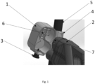
- a holder for a charging gun is presented in details in Fig. 1 . It comprises a housing 1 configured for receiving an end portion 7 of a charging gun 2, preferably CCS or CCS-2 type, such that connector pins located at the end portion 7 of the charging gun 2 are totally covered by the housing 1 of the holder.
- a housing 1 configured for receiving an end portion 7 of a charging gun 2, preferably CCS or CCS-2 type, such that connector pins located at the end portion 7 of the charging gun 2 are totally covered by the housing 1 of the holder.
- Such housing 1 enables protection of connector pins from environment conditions such as dust, water drops and moisture.
- the holder also comprises a protecting means 3, configured for holding the charging gun 2 in a designated position.
- a protecting means 3 prevents charging gun from being accidentally pulled out from the housing 1.
- the holder comprises a connecting means 4 that is configured for attaching the housing 1 to a cable 5.
- the holder can be thus stably connected to the cable at a desired height, preferably up to 6m.
- the protecting means 3 is in a form of a blocking pin with a handle, wherein the handle is located on the outer side of the housing 1. Holding the charging gun in one hand and the handle of blocking pin in other we are shifting the charging gun into to the housing of the gun holder. By releasing the handle of blocking pin the position of charging gun will be fixed. The blocking pin jumps to the hole in the CCS (CCS-2) plug slot.
- the housing 1 is configured for receiving the charging gun 2 in the housing 1 by press-fitting. This ensures tight and stable placement of the charging gun 2 in the holder
- the protecting means 3 is in a form of a hook attached to the housing 1, configured for engaging the hook with a corresponding protrusion on the surface of the charging gun 2.
- the housing 1 is made of a non-conductive material. This increases safety of the users and people gathered around the holder and also increases safety of the place in which the charging station is mounted.
- the housing 1 is made of a polymer.
- the holder is inclined relative to the cable 5 at an angle of less than 90°. This causes, that the water from the rain or any other pollutions do not stay on the surface of the housing 1 but drops to the ground.
- the charging gun 2 comprises an adapter 6 configured for aligning the position of the charging gun 2 inside the housing 1. This causes that the charging gun 2 is stronger placed inside the housing 2. This solves the problem of empty space between the housing 1 and one part of the end portion 7 of the charging gun 2 that is shorter than the other.
- the adapter 6 is in form of a grid however the person skilled in the art will know that it may be in any other shape that solves this problem.
- a device with a charging gun 2 and a cable 5 connected to the charging unit is disclosed.
- the cable 5 comprising a holder according to the invention is shown in details in Fig. 2 .
- the holder is attached to the cable 5 as previously described.
Landscapes
- Engineering & Computer Science (AREA)
- Power Engineering (AREA)
- Transportation (AREA)
- Mechanical Engineering (AREA)
- Microelectronics & Electronic Packaging (AREA)
- Electric Propulsion And Braking For Vehicles (AREA)
- Charge And Discharge Circuits For Batteries Or The Like (AREA)
Abstract
The present invention relates to a holder for a charging gun, in particular to CCS or CCS-2 charging gun type, and to a device with a holder for a charging gun.The invention relates to a holder for a charging gun, comprising:- a housing (1) configured for receiving an end portion (7) of a charging gun (2), preferably CCS or CCS-2 type such that connector pins located at the end portion (7) of the charging gun (2) are totally covered by the housing (1) of the holder,- a protecting means (3), configured for holding the charging gun (2) in a designated position,- a connecting means (4) that is configured for attaching the housing (1) to a cable (5).The subject of the invention is also a device with a charging gun (2) and a cable (5) comprising a holder
Description
- The present invention relates to a holder for a charging gun, in particular to CCS or CCS-2 charging gun type, and to a device with a holder for a charging gun.
- In application such as bus depos, tracks parking's, cars parking's or garage's, where the CCS or CCS-2 distribution box is mounted height above the ground (up to 6 m) and the charging cable with the charging gun freely hang out to the ground. There is a need to protect and service the charging gun. The plug mounted at the end of the charging gun has no cover therefore the connector pins are exposed to external environment conditions such as dust, water drops and moisture. Also in the situation where the cable is longer than the distance from distribution box to the ground, the cable will simple lie on the ground. Therefore there is need to protect the connector pins from external conditions and to service of the excess of the cable.
- According to a first example of the disclosure a holder for a charging gun, comprising:
- a housing configured for receiving an end portion of a charging gun, preferably CCS or CCS-2 type such that connector pins located at the end portion of the charging gun are totally covered by the housing of the holder,
- a protecting means, configured for holding the charging gun in a designated position,
- a connecting means that is configured for attaching the housing to a cable.
- Preferably, the protecting means is in a form of a blocking pin with a handle, wherein the handle is located on the outer side of the housing.
- Preferably, the housing is configured for receiving the charging gun in the housing by press-fitting.
- Preferably, the protecting means is in a form of a hook attached to the housing, configured for engaging the hook with a corresponding protrusion on the surface of the charging gun.
- Preferably, the housing is made of a non-conductive material.
- Preferably, the housing is made of a polymer.
- Preferably, the holder is inclined relative to the cable at an angle of less than 90°.
- Preferably, the holder comprises an adapter configured for aligning the position of the charging gun inside the housing.
- Preferably, the adapter is in form of a grid.
- Preferably, the connecting means is in the form of an element configured for attaching it to the housing in such a way that it is rigidly attached to the cable.
- According to a second example of the disclosure a device with a charging gun and a cable comprising a holder.
- Preferred embodiment of the present invention are presented in a more detailed way with reference to the attached drawing, in which:
-
Figure 1 shows a holder, -
Figure 2 shows a part of a device with a cable comprising a holder for the charging gun. - A holder for a charging gun is presented in details in
Fig. 1 . It comprises ahousing 1 configured for receiving anend portion 7 of acharging gun 2, preferably CCS or CCS-2 type, such that connector pins located at theend portion 7 of thecharging gun 2 are totally covered by thehousing 1 of the holder.Such housing 1 enables protection of connector pins from environment conditions such as dust, water drops and moisture. - The holder also comprises a protecting
means 3, configured for holding thecharging gun 2 in a designated position. Such protecting means 3 prevents charging gun from being accidentally pulled out from thehousing 1. - Moreover, the holder comprises a
connecting means 4 that is configured for attaching thehousing 1 to acable 5. The holder can be thus stably connected to the cable at a desired height, preferably up to 6m. - According to the first embodiment of the invention, the protecting
means 3 is in a form of a blocking pin with a handle, wherein the handle is located on the outer side of thehousing 1. Holding the charging gun in one hand and the handle of blocking pin in other we are shifting the charging gun into to the housing of the gun holder. By releasing the handle of blocking pin the position of charging gun will be fixed. The blocking pin jumps to the hole in the CCS (CCS-2) plug slot. - According to the second embodiment, the
housing 1 is configured for receiving thecharging gun 2 in thehousing 1 by press-fitting. This ensures tight and stable placement of thecharging gun 2 in the holder - According to the third aspect of the invention, the protecting
means 3 is in a form of a hook attached to thehousing 1, configured for engaging the hook with a corresponding protrusion on the surface of thecharging gun 2. - Preferably the
housing 1 is made of a non-conductive material. This increases safety of the users and people gathered around the holder and also increases safety of the place in which the charging station is mounted. - Preferably, the
housing 1 is made of a polymer. - Preferably, the holder is inclined relative to the
cable 5 at an angle of less than 90°. This causes, that the water from the rain or any other pollutions do not stay on the surface of thehousing 1 but drops to the ground. - Preferably, it comprises an
adapter 6 configured for aligning the position of thecharging gun 2 inside thehousing 1. This causes that thecharging gun 2 is stronger placed inside thehousing 2. This solves the problem of empty space between thehousing 1 and one part of theend portion 7 of thecharging gun 2 that is shorter than the other. - Preferably the
adapter 6 is in form of a grid however the person skilled in the art will know that it may be in any other shape that solves this problem. - Preferably, the
connecting means 4 is in the form of an element configured for attaching it to thehousing 1 in such a way that it is attached to thecable 5, preferably it is fixedly attached to thecable 5. This connection can be formed by tightening theconnecting means 4 to thehousing 1 by screws, by glue or in any other possible way that is known for the person skilled in the art. - In a second example a device with a
charging gun 2 and acable 5 connected to the charging unit is disclosed. Thecable 5 comprising a holder according to the invention is shown in details inFig. 2 . The holder is attached to thecable 5 as previously described. - Such device solves the problem of a need to service the excess of the
cable 5, because the holder is mounted directly on thecable 5. The excess of the cable will not lie on the ground what improve safety of the crossing by people and is less vulnerable for any kind of damages which may occur while thecable 5 and/or thecharging gun 2 is laying on a ground.
Claims (11)
- A holder for a charging gun, comprising:- a housing (1) configured for receiving an end portion (7) of a charging gun (2), preferably CCS or CCS-2 type such that connector pins located at the end portion (7) of the charging gun (2) are totally covered by the housing (1) of the holder,- a protecting means (3), configured for holding the charging gun (2) in a designated position,- a connecting means (4) that is configured for attaching the housing (1) to a cable (5).
- The holder, according to claim 1, characterised in that the protecting means (3) is in a form of a blocking pin with a handle, wherein the handle is located on the outer side of the housing (1).
- The holder, according to claim 1, characterised in that the housing (1) is configured for receiving the charging gun (2) in the housing (1) by press-fitting.
- The holder, according to claim 1, characterised in that the protecting means (3) is in a form of a hook attached to the housing (1), configured for engaging the hook with a corresponding protrusion on the surface of the charging gun (2).
- The holder, according to any one of the preceeding claims, characterised in that the housing (1) is made of a non-conductive material.
- The holder, according to any one of the preceeding claims, characterised in that the housing (1) is made of a polymer.
- The holder, according to any one of the claims 1-6, characterised in that it is inclined relative to the cable (5) at an angle of less than 90°.
- The holder, according to any one of the claims 1-7, characterised in that it comprises an adapter (6) configured for aligning the position of the charging gun (2) inside the housing (1).
- The holder, according to claim 8, characterised in that the adapter (6) is in form of a grid.
- The holder, according to any one of the claims 1-9, characterised in that the connecting means (4) is in the form of an element configured for attaching it to the housing (1) in such a way that it is rigidly attached to the cable (5).
- A charging device with a charging gun (2) and a cable (5) connected to the charging unit, wherein the cable (5) comprising a holder according to any one of the preceding claims.
Priority Applications (3)
| Application Number | Priority Date | Filing Date | Title |
|---|---|---|---|
| EP23206279.4A EP4546597A1 (en) | 2023-10-26 | 2023-10-26 | Holder for a charging gun and charging device with a holder for a charging gun |
| CN202411494818.3A CN119898214A (en) | 2023-10-26 | 2024-10-24 | Holder for a charging gun and charging device having a holder for a charging gun |
| US18/926,539 US20250141245A1 (en) | 2023-10-26 | 2024-10-25 | Holder for a Charging Gun and Charging Device with a Holder for a Charging Gun |
Applications Claiming Priority (1)
| Application Number | Priority Date | Filing Date | Title |
|---|---|---|---|
| EP23206279.4A EP4546597A1 (en) | 2023-10-26 | 2023-10-26 | Holder for a charging gun and charging device with a holder for a charging gun |
Publications (1)
| Publication Number | Publication Date |
|---|---|
| EP4546597A1 true EP4546597A1 (en) | 2025-04-30 |
Family
ID=88598707
Family Applications (1)
| Application Number | Title | Priority Date | Filing Date |
|---|---|---|---|
| EP23206279.4A Pending EP4546597A1 (en) | 2023-10-26 | 2023-10-26 | Holder for a charging gun and charging device with a holder for a charging gun |
Country Status (3)
| Country | Link |
|---|---|
| US (1) | US20250141245A1 (en) |
| EP (1) | EP4546597A1 (en) |
| CN (1) | CN119898214A (en) |
Citations (4)
| Publication number | Priority date | Publication date | Assignee | Title |
|---|---|---|---|---|
| DE102018115123A1 (en) * | 2018-03-20 | 2019-09-26 | Günther Spelsberg GmbH & Co. KG | Wall charging station for charging an electric vehicle |
| EP3570383A1 (en) * | 2018-05-14 | 2019-11-20 | Solaredge Technologies Ltd. | Inlet for electrical plug |
| DE102020132723A1 (en) * | 2020-12-09 | 2022-06-09 | Phoenix Contact E-Mobility Gmbh | Connector holder |
| WO2022193018A1 (en) * | 2021-03-16 | 2022-09-22 | Pirie Christopher Ian | Electric vehicle charging station with safety features |
Family Cites Families (3)
| Publication number | Priority date | Publication date | Assignee | Title |
|---|---|---|---|---|
| JP6102012B2 (en) * | 2011-10-24 | 2017-03-29 | パナソニックIpマネジメント株式会社 | Charge control device |
| EP4384411A4 (en) * | 2021-08-11 | 2025-11-05 | Itt Cannon Gmbh | ELECTRIC VEHICLE CHARGING ARRANGEMENT |
| WO2025002474A1 (en) * | 2023-06-26 | 2025-01-02 | 上海阪辉新能源科技有限公司 | Charging device for electric vehicle, and three-dimensional garage |
-
2023
- 2023-10-26 EP EP23206279.4A patent/EP4546597A1/en active Pending
-
2024
- 2024-10-24 CN CN202411494818.3A patent/CN119898214A/en active Pending
- 2024-10-25 US US18/926,539 patent/US20250141245A1/en active Pending
Patent Citations (4)
| Publication number | Priority date | Publication date | Assignee | Title |
|---|---|---|---|---|
| DE102018115123A1 (en) * | 2018-03-20 | 2019-09-26 | Günther Spelsberg GmbH & Co. KG | Wall charging station for charging an electric vehicle |
| EP3570383A1 (en) * | 2018-05-14 | 2019-11-20 | Solaredge Technologies Ltd. | Inlet for electrical plug |
| DE102020132723A1 (en) * | 2020-12-09 | 2022-06-09 | Phoenix Contact E-Mobility Gmbh | Connector holder |
| WO2022193018A1 (en) * | 2021-03-16 | 2022-09-22 | Pirie Christopher Ian | Electric vehicle charging station with safety features |
Also Published As
| Publication number | Publication date |
|---|---|
| CN119898214A (en) | 2025-04-29 |
| US20250141245A1 (en) | 2025-05-01 |
Similar Documents
| Publication | Publication Date | Title |
|---|---|---|
| US9535226B2 (en) | Modular breakout device for optical and electrical connections | |
| US11579374B2 (en) | Hybrid ingress protected connector and adapter assembly | |
| KR101083416B1 (en) | Underground distribution line protective insulation connector | |
| CA2811671C (en) | Environmentally sealed cable breakout assemblies | |
| US8727818B2 (en) | Termination bar assembly | |
| US9645341B2 (en) | Cable assembly with connector having twist ability for aligning mating features | |
| CA3092542A1 (en) | A plug cap assembly | |
| WO2011025539A1 (en) | Electrical connector for terminating the end of an electrical cable | |
| US9784937B2 (en) | Cable assembly having electrical power conductors and fiber optic data lines | |
| KR102295513B1 (en) | Protection cover for electric wire | |
| KR102497929B1 (en) | Terminal Box For Optical Fiber and Power Line Composite Cable And Optical Fiber and Power Line Composite Cable | |
| US20250141245A1 (en) | Holder for a Charging Gun and Charging Device with a Holder for a Charging Gun | |
| CA3080376C (en) | Insulator insert for service entrance cap | |
| AU2020202803B2 (en) | Coaxial cable assembly | |
| KR100839614B1 (en) | Wire sheath with ground wire | |
| US4733020A (en) | Dielectric utility cable guard | |
| CN213425305U (en) | Waterproof wire harness | |
| CN207320744U (en) | A kind of pre-branched cable protective case | |
| KR200454869Y1 (en) | Type of cable hanger | |
| CN208334734U (en) | A kind of telecommunication optical fiber is to family terminal box | |
| CN113922175A (en) | Marine battery charger cable extender | |
| KR20220084495A (en) | Protection cover for cable with built-in earth cable | |
| KR101612938B1 (en) | A Protection Apparatus for Connecting Cable | |
| CN217063171U (en) | Rubber electric sheath | |
| AU2014212574A1 (en) | Cable assembly having electrical power conductors and fiber optic data lines |
Legal Events
| Date | Code | Title | Description |
|---|---|---|---|
| PUAI | Public reference made under article 153(3) epc to a published international application that has entered the european phase |
Free format text: ORIGINAL CODE: 0009012 |
|
| STAA | Information on the status of an ep patent application or granted ep patent |
Free format text: STATUS: THE APPLICATION HAS BEEN PUBLISHED |
|
| AK | Designated contracting states |
Kind code of ref document: A1 Designated state(s): AL AT BE BG CH CY CZ DE DK EE ES FI FR GB GR HR HU IE IS IT LI LT LU LV MC ME MK MT NL NO PL PT RO RS SE SI SK SM TR |
|
| STAA | Information on the status of an ep patent application or granted ep patent |
Free format text: STATUS: REQUEST FOR EXAMINATION WAS MADE |
|
| 17P | Request for examination filed |
Effective date: 20251030 |