EP4546573A1 - CONNECTOR ARRANGEMENT AND CONNECTORS - Google Patents
CONNECTOR ARRANGEMENT AND CONNECTORS Download PDFInfo
- Publication number
- EP4546573A1 EP4546573A1 EP24199328.6A EP24199328A EP4546573A1 EP 4546573 A1 EP4546573 A1 EP 4546573A1 EP 24199328 A EP24199328 A EP 24199328A EP 4546573 A1 EP4546573 A1 EP 4546573A1
- Authority
- EP
- European Patent Office
- Prior art keywords
- connector
- housing
- connection port
- passage
- passage connection
- Prior art date
- Legal status (The legal status is an assumption and is not a legal conclusion. Google has not performed a legal analysis and makes no representation as to the accuracy of the status listed.)
- Granted
Links
Images





Classifications
-
- A—HUMAN NECESSITIES
- A61—MEDICAL OR VETERINARY SCIENCE; HYGIENE
- A61B—DIAGNOSIS; SURGERY; IDENTIFICATION
- A61B5/00—Measuring for diagnostic purposes; Identification of persons
- A61B5/02—Detecting, measuring or recording for evaluating the cardiovascular system, e.g. pulse, heart rate, blood pressure or blood flow
- A61B5/0205—Simultaneously evaluating both cardiovascular conditions and different types of body conditions, e.g. heart and respiratory condition
- A61B5/02055—Simultaneously evaluating both cardiovascular condition and temperature
-
- A—HUMAN NECESSITIES
- A61—MEDICAL OR VETERINARY SCIENCE; HYGIENE
- A61B—DIAGNOSIS; SURGERY; IDENTIFICATION
- A61B5/00—Measuring for diagnostic purposes; Identification of persons
- A61B5/02—Detecting, measuring or recording for evaluating the cardiovascular system, e.g. pulse, heart rate, blood pressure or blood flow
- A61B5/021—Measuring pressure in heart or blood vessels
-
- A—HUMAN NECESSITIES
- A61—MEDICAL OR VETERINARY SCIENCE; HYGIENE
- A61B—DIAGNOSIS; SURGERY; IDENTIFICATION
- A61B5/00—Measuring for diagnostic purposes; Identification of persons
- A61B5/02—Detecting, measuring or recording for evaluating the cardiovascular system, e.g. pulse, heart rate, blood pressure or blood flow
- A61B5/024—Measuring pulse rate or heart rate
- A61B5/02438—Measuring pulse rate or heart rate with portable devices, e.g. worn by the patient
-
- A—HUMAN NECESSITIES
- A61—MEDICAL OR VETERINARY SCIENCE; HYGIENE
- A61B—DIAGNOSIS; SURGERY; IDENTIFICATION
- A61B5/00—Measuring for diagnostic purposes; Identification of persons
- A61B5/24—Detecting, measuring or recording bioelectric or biomagnetic signals of the body or parts thereof
- A61B5/25—Bioelectric electrodes therefor
- A61B5/251—Means for maintaining electrode contact with the body
- A61B5/256—Wearable electrodes, e.g. having straps or bands
-
- A—HUMAN NECESSITIES
- A61—MEDICAL OR VETERINARY SCIENCE; HYGIENE
- A61B—DIAGNOSIS; SURGERY; IDENTIFICATION
- A61B5/00—Measuring for diagnostic purposes; Identification of persons
- A61B5/24—Detecting, measuring or recording bioelectric or biomagnetic signals of the body or parts thereof
- A61B5/25—Bioelectric electrodes therefor
- A61B5/271—Arrangements of electrodes with cords, cables or leads, e.g. single leads or patient cord assemblies
-
- A—HUMAN NECESSITIES
- A61—MEDICAL OR VETERINARY SCIENCE; HYGIENE
- A61B—DIAGNOSIS; SURGERY; IDENTIFICATION
- A61B5/00—Measuring for diagnostic purposes; Identification of persons
- A61B5/24—Detecting, measuring or recording bioelectric or biomagnetic signals of the body or parts thereof
- A61B5/316—Modalities, i.e. specific diagnostic methods
- A61B5/318—Heart-related electrical modalities, e.g. electrocardiography [ECG]
-
- A—HUMAN NECESSITIES
- A61—MEDICAL OR VETERINARY SCIENCE; HYGIENE
- A61B—DIAGNOSIS; SURGERY; IDENTIFICATION
- A61B5/00—Measuring for diagnostic purposes; Identification of persons
- A61B5/68—Arrangements of detecting, measuring or recording means, e.g. sensors, in relation to patient
- A61B5/6801—Arrangements of detecting, measuring or recording means, e.g. sensors, in relation to patient specially adapted to be attached to or worn on the body surface
- A61B5/6802—Sensor mounted on worn items
- A61B5/6804—Garments; Clothes
-
- H—ELECTRICITY
- H01—ELECTRIC ELEMENTS
- H01R—ELECTRICALLY-CONDUCTIVE CONNECTIONS; STRUCTURAL ASSOCIATIONS OF A PLURALITY OF MUTUALLY-INSULATED ELECTRICAL CONNECTING ELEMENTS; COUPLING DEVICES; CURRENT COLLECTORS
- H01R12/00—Structural associations of a plurality of mutually-insulated electrical connecting elements, specially adapted for printed circuits, e.g. printed circuit boards [PCB], flat or ribbon cables, or like generally planar structures, e.g. terminal strips, terminal blocks; Coupling devices specially adapted for printed circuits, flat or ribbon cables, or like generally planar structures; Terminals specially adapted for contact with, or insertion into, printed circuits, flat or ribbon cables, or like generally planar structures
- H01R12/50—Fixed connections
- H01R12/59—Fixed connections for flexible printed circuits, flat or ribbon cables or like structures
-
- H—ELECTRICITY
- H01—ELECTRIC ELEMENTS
- H01R—ELECTRICALLY-CONDUCTIVE CONNECTIONS; STRUCTURAL ASSOCIATIONS OF A PLURALITY OF MUTUALLY-INSULATED ELECTRICAL CONNECTING ELEMENTS; COUPLING DEVICES; CURRENT COLLECTORS
- H01R12/00—Structural associations of a plurality of mutually-insulated electrical connecting elements, specially adapted for printed circuits, e.g. printed circuit boards [PCB], flat or ribbon cables, or like generally planar structures, e.g. terminal strips, terminal blocks; Coupling devices specially adapted for printed circuits, flat or ribbon cables, or like generally planar structures; Terminals specially adapted for contact with, or insertion into, printed circuits, flat or ribbon cables, or like generally planar structures
- H01R12/70—Coupling devices
- H01R12/71—Coupling devices for rigid printing circuits or like structures
- H01R12/72—Coupling devices for rigid printing circuits or like structures coupling with the edge of the rigid printed circuits or like structures
- H01R12/722—Coupling devices for rigid printing circuits or like structures coupling with the edge of the rigid printed circuits or like structures coupling devices mounted on the edge of the printed circuits
- H01R12/724—Coupling devices for rigid printing circuits or like structures coupling with the edge of the rigid printed circuits or like structures coupling devices mounted on the edge of the printed circuits containing contact members forming a right angle
-
- H—ELECTRICITY
- H01—ELECTRIC ELEMENTS
- H01R—ELECTRICALLY-CONDUCTIVE CONNECTIONS; STRUCTURAL ASSOCIATIONS OF A PLURALITY OF MUTUALLY-INSULATED ELECTRICAL CONNECTING ELEMENTS; COUPLING DEVICES; CURRENT COLLECTORS
- H01R13/00—Details of coupling devices of the kinds covered by groups H01R12/70 or H01R24/00 - H01R33/00
- H01R13/005—Electrical coupling combined with fluidic coupling
-
- H—ELECTRICITY
- H01—ELECTRIC ELEMENTS
- H01R—ELECTRICALLY-CONDUCTIVE CONNECTIONS; STRUCTURAL ASSOCIATIONS OF A PLURALITY OF MUTUALLY-INSULATED ELECTRICAL CONNECTING ELEMENTS; COUPLING DEVICES; CURRENT COLLECTORS
- H01R13/00—Details of coupling devices of the kinds covered by groups H01R12/70 or H01R24/00 - H01R33/00
- H01R13/46—Bases; Cases
- H01R13/514—Bases; Cases composed as a modular blocks or assembly, i.e. composed of co-operating parts provided with contact members or holding contact members between them
-
- H—ELECTRICITY
- H01—ELECTRIC ELEMENTS
- H01R—ELECTRICALLY-CONDUCTIVE CONNECTIONS; STRUCTURAL ASSOCIATIONS OF A PLURALITY OF MUTUALLY-INSULATED ELECTRICAL CONNECTING ELEMENTS; COUPLING DEVICES; CURRENT COLLECTORS
- H01R13/00—Details of coupling devices of the kinds covered by groups H01R12/70 or H01R24/00 - H01R33/00
- H01R13/46—Bases; Cases
- H01R13/516—Means for holding or embracing insulating body, e.g. casing, hoods
-
- H—ELECTRICITY
- H01—ELECTRIC ELEMENTS
- H01R—ELECTRICALLY-CONDUCTIVE CONNECTIONS; STRUCTURAL ASSOCIATIONS OF A PLURALITY OF MUTUALLY-INSULATED ELECTRICAL CONNECTING ELEMENTS; COUPLING DEVICES; CURRENT COLLECTORS
- H01R13/00—Details of coupling devices of the kinds covered by groups H01R12/70 or H01R24/00 - H01R33/00
- H01R13/46—Bases; Cases
- H01R13/516—Means for holding or embracing insulating body, e.g. casing, hoods
- H01R13/518—Means for holding or embracing insulating body, e.g. casing, hoods for holding or embracing several coupling parts, e.g. frames
-
- H—ELECTRICITY
- H01—ELECTRIC ELEMENTS
- H01R—ELECTRICALLY-CONDUCTIVE CONNECTIONS; STRUCTURAL ASSOCIATIONS OF A PLURALITY OF MUTUALLY-INSULATED ELECTRICAL CONNECTING ELEMENTS; COUPLING DEVICES; CURRENT COLLECTORS
- H01R13/00—Details of coupling devices of the kinds covered by groups H01R12/70 or H01R24/00 - H01R33/00
- H01R13/46—Bases; Cases
- H01R13/52—Dustproof, splashproof, drip-proof, waterproof, or flameproof cases
- H01R13/5224—Dustproof, splashproof, drip-proof, waterproof, or flameproof cases for medical use
-
- A—HUMAN NECESSITIES
- A61—MEDICAL OR VETERINARY SCIENCE; HYGIENE
- A61B—DIAGNOSIS; SURGERY; IDENTIFICATION
- A61B5/00—Measuring for diagnostic purposes; Identification of persons
- A61B5/68—Arrangements of detecting, measuring or recording means, e.g. sensors, in relation to patient
- A61B5/6801—Arrangements of detecting, measuring or recording means, e.g. sensors, in relation to patient specially adapted to be attached to or worn on the body surface
- A61B5/6802—Sensor mounted on worn items
-
- H—ELECTRICITY
- H01—ELECTRIC ELEMENTS
- H01R—ELECTRICALLY-CONDUCTIVE CONNECTIONS; STRUCTURAL ASSOCIATIONS OF A PLURALITY OF MUTUALLY-INSULATED ELECTRICAL CONNECTING ELEMENTS; COUPLING DEVICES; CURRENT COLLECTORS
- H01R12/00—Structural associations of a plurality of mutually-insulated electrical connecting elements, specially adapted for printed circuits, e.g. printed circuit boards [PCB], flat or ribbon cables, or like generally planar structures, e.g. terminal strips, terminal blocks; Coupling devices specially adapted for printed circuits, flat or ribbon cables, or like generally planar structures; Terminals specially adapted for contact with, or insertion into, printed circuits, flat or ribbon cables, or like generally planar structures
- H01R12/50—Fixed connections
- H01R12/59—Fixed connections for flexible printed circuits, flat or ribbon cables or like structures
- H01R12/63—Fixed connections for flexible printed circuits, flat or ribbon cables or like structures connecting to another shape cable
-
- H—ELECTRICITY
- H01—ELECTRIC ELEMENTS
- H01R—ELECTRICALLY-CONDUCTIVE CONNECTIONS; STRUCTURAL ASSOCIATIONS OF A PLURALITY OF MUTUALLY-INSULATED ELECTRICAL CONNECTING ELEMENTS; COUPLING DEVICES; CURRENT COLLECTORS
- H01R12/00—Structural associations of a plurality of mutually-insulated electrical connecting elements, specially adapted for printed circuits, e.g. printed circuit boards [PCB], flat or ribbon cables, or like generally planar structures, e.g. terminal strips, terminal blocks; Coupling devices specially adapted for printed circuits, flat or ribbon cables, or like generally planar structures; Terminals specially adapted for contact with, or insertion into, printed circuits, flat or ribbon cables, or like generally planar structures
- H01R12/70—Coupling devices
- H01R12/7005—Guiding, mounting, polarizing or locking means; Extractors
- H01R12/7011—Locking or fixing a connector to a PCB
- H01R12/7052—Locking or fixing a connector to a PCB characterised by the locating members
-
- H—ELECTRICITY
- H01—ELECTRIC ELEMENTS
- H01R—ELECTRICALLY-CONDUCTIVE CONNECTIONS; STRUCTURAL ASSOCIATIONS OF A PLURALITY OF MUTUALLY-INSULATED ELECTRICAL CONNECTING ELEMENTS; COUPLING DEVICES; CURRENT COLLECTORS
- H01R2201/00—Connectors or connections adapted for particular applications
- H01R2201/12—Connectors or connections adapted for particular applications for medicine and surgery
Definitions
- the present invention relates to a connector assembly and a connector, particularly to a connector assembly in which a second connector that is attached to a tip of a fluid distribution tube is fitted, along a fitting direction, to a first connector that is mounted on a flexible mounting object.
- smart clothes that can obtain user's biological data such as the heart rate and the body temperature only by being worn by the user.
- Such smart clothes have an electrode disposed at a measurement site, and when a wearable device serving as a measurement device is electrically connected to the electrode, biological data can be transmitted to the wearable device.
- the electrode and the wearable device can be interconnected by, for instance, use of a connector for garments that is mounted on a garment as smart clothes.
- the connector for garments as described above has difficulty in distributing a fluid such as air although the connector is capable of electric connection.
- WO 2016/132879 discloses a connecting device that performs connection of a fluid passage for distributing air, liquids, or the like and electric connection between a subject and a measurement apparatus at a time.
- the connecting device includes a living body-side connector 1 and a measurement apparatus-side connector 2 as shown in FIG. 31 .
- the living body-side connector 1 includes a housing 1A, a plurality of connection terminals 1B held by the housing 1A and attached to an end portion of a living body-side cable 3, and a connection port 1C held by the housing 1A and connected to an end portion of a living body-side tube 4.
- the measurement apparatus-side connector 2 includes a housing 2A, a plurality of connection terminals 2B held by the housing 2A and attached to an end portion of the measurement apparatus-side cable 5, and a connection port 2C held by the housing 2A and connected to an end portion of a measurement apparatus-side tube 6.
- connection port 1C of the living body-side connector 1 is composed of a rear end-side nozzle portion 1D joined to the end portion of the living body-side tube 4 and a tip end-side nozzle portion 1E joined to the rear end-side nozzle portion 1D with a tube joint and attached to the housing 1A
- connection port 2C of the measurement apparatus-side connector 2 is composed of a rear end-side nozzle portion 2D joined to the end portion of the measurement apparatus-side tube 6 and a tip end-side nozzle portion 2E joined to the rear end-side nozzle portion 2D with a tube joint and attached to the housing 2A.
- connection port 1C of the living body-side connector 1 it is necessary to attach the tip end-side nozzle portion 1E to the housing 1A and join the rear end-side nozzle portion 1D to the tip end-side nozzle portion 1E with a tube joint
- connection port 2C of the measurement apparatus-side connector 2 it is necessary to attach the tip end-side nozzle portion 2E to the housing 2A and join the rear end-side nozzle portion 2D to the tip end-side nozzle portion 2E with a tube joint, resulting in complicated production process of the connecting device, disadvantageously.
- the present invention has been made in order to solve the conventional problems described above and aims at providing a connector assembly and a connector that can be mounted on a flexible mounting object and can perform electric connection and connection of a fluid passage at a time while easy production thereof is possible.
- the connector assembly according to the present invention is a connector assembly in which a second connector is fitted to a first connector along a fitting direction, the second connector being attached to a tip of a fluid distribution tube, and the first connector being mounted on a mounting object that is flexible and is provided with a wiring portion, wherein the first connector includes:
- the connector according to the present invention is a connector which is mounted on a mounting object and to which a counter connector is fitted along a fitting direction, the mounting object being flexible and being provided with a wiring portion, the connector comprising:
- FIGS. 1 and 2 show a connector assembly according to Embodiment 1 in the non-fitted state.
- the connector assembly is composed of a first connector (connector) 11 and a second connector (counter connector) 21 to be fitted to each other along a fitting direction.
- the first connector 11 includes a first housing (housing) 12 mounted on a flexible mounting object C such as fabric of a garment, for example, and the second connector 21 includes a second housing 22 attached to a tip of a fluid distribution tube P1.
- the mounting object C is defined as extending along an XY plane, the direction in which the fluid distribution tube P1 extends is referred to as "Y direction,” and the direction from the first connector 11 to the second connector 21 is referred to as "+Z direction.”
- the Z direction is the fitting direction in which the first connector 11 and the second connector 21 are fitted together.
- the second connector 21 is disposed on the +Z direction side of the mounting object C, and a mounting object-side distribution tube P2 is joined to the first housing 12 of the first connector 11 on the -Z direction side of the mounting object C.
- FIG. 3 shows an assembly view of the first connector 11.
- the first housing 12 is made of an insulating resin and is formed of a first bottom insulator 13 disposed on the - Z direction side of the mounting object C, and a first top insulator 14 disposed on the +Z direction side of the mounting object C.
- a pair of first contact members (contact members) 15 are disposed on the -Z direction side of the first top insulator 14, a reinforcement sheet 16 is disposed on the -Z direction side of the pair of first contact members 15, and the mounting object C is disposed on the -Z direction side of the reinforcement sheet 16. Furthermore, the first bottom insulator 13 is disposed on the -Z direction side of the mounting object C via an O-ring 17, and the mounting object-side distribution tube P2 is disposed on the -Z direction side of the first bottom insulator 13.
- the first bottom insulator 13 includes a flat plate portion 13A extending along an XY plane, and, at a center portion of the flat plate portion 13A, a passage connection port 13B of cylindrical shape is integrally formed to extend from the +Z directional surface of the flat plate portion 13A in the +Z direction.
- the passage connection port 13B is provided in its interior with a linking passage 13C extending in the Z direction and penetrating the first bottom insulator 13.
- the linking passage 13C penetrates the first bottom insulator 13, whereby an opening end portion of the linking passage 13C constitutes a first distribution port R1 opening toward an outside of the first connector 11 in the -Z directional surface of the flat plate portion 13A.
- an annual groove 13D is formed along an XY plane to surround the passage connection port 13B.
- the +Z directional surface of the flat plate portion 13A is provided with a pair of projections 13E projecting in the +Z direction and formed on opposite sides of the passage connection port 13B in the Y direction across the passage connection port 13B.
- a plurality of through-holes 13F are formed in the vicinity of a peripheral edge portion of the flat plate portion 13A.
- the first top insulator 14 includes a recessed second connector accommodation portion 14A opening in the +Z direction, and, at a center portion of the second connector accommodation portion 14A, a connection port through-hole 14B is formed to penetrate the first top insulator 14 in the Z direction.
- a pair of contact through-holes 14C are also formed on opposite sides of the connection port through hole 14B in the Y direction across the connection port through-hole 14B to penetrate the first top insulator 14 in the Z direction.
- a plurality of bosses 14D are formed to project in the -Z direction.
- the plurality of bosses 14D separately correspond to the plurality of through-holes 13F of the first bottom insulator 13.
- the reinforcement sheet 16 is used to reinforce the mounting object C on which the first connector 11 is mounted.
- the reinforcement sheet 16 is made of an insulating material and provided at its center with an opening portion 16A. Further, a plurality of cutouts 16B separately corresponding to the plurality of bosses 14D of the first top insulator 14 are formed along the periphery of the opening portion 16A of the reinforcement sheet 16.
- the first contact member 15 is made of an electrically conductive material such as metal and includes: a tubular portion 15A of cylindrical shape projecting in the +Z direction; and a flange 15B of disc shape extending in a radial direction along an XY plane from the outer periphery of a -Z directional end portion of the tubular portion 15A.
- the tubular portion 15A is provided in its interior with a recessed portion 15C opening in the -Z direction.
- the mounting object C is formed of, for example, fabric of a garment, and is provided with a single through-hole C1 through which the passage connection port 13B of the first bottom insulator 13 passes, and a plurality of through-holes C2 disposed around the through-hole C1 and corresponding to the plurality of bosses 14D of the first top insulator 14.
- the mounting object C is also provided with a pair of wiring portions C3 and a pair of electrodes C4 formed of, for example, embroidery using embroidery threads made of a conductive thread.
- the pair of wiring portions C3 separately extend in the +Y direction and the -Y direction form the vicinity of the through-hole C1 and are connected to the corresponding electrodes C4.
- the tubular portion 15A of the first contact member 15 is inserted to the corresponding one of the pair of contact through-holes 14C of the first top insulator 14 from the -Z direction, and the plurality of bosses 14D of the first top insulator 14 are sequentially inserted to the plurality of cutouts 16B of the reinforcement sheet 16 and the plurality of through-holes C2 of the mounting object C.
- the pair of first contact members 15 are situated within the opening portion 16A of the reinforcement sheet 16, and the connection port through-hole 14B of the first top insulator 14 is situated at a position overlapping the through-hole C1 of the mounting object C on the +Z direction side.
- the O-ring 17 is fitted into the annular groove 13D of the passage connection port 13B of the first bottom insulator 13, and the first bottom insulator 13 is pressed from the -Z direction side of the mounting object C toward the first top insulator 14, with the mounting object C being held therebetween.
- the first bottom insulator 13 is pressed from the -Z direction side of the mounting object C toward the first top insulator 14, with the mounting object C being held therebetween.
- the passage connection port 13B of the first bottom insulator 13 passes through the through-hole C1 of the mounting object C and the connection port through-hole 14B of the first top insulator 14 to project in the second connector accommodation portion 14A of the first top insulator 14, and the pair of projections 13E of the first bottom insulator 13 are separately inserted into the recessed portions 15C of the corresponding first contact members 15 while pushing the pair of wiring portions C3 of the mounting object C therein.
- the wiring portion C3 of the mounting object C pushed into the recessed portion 15C of the first contact member 15 is held between a lateral surface of the projection 13E of the first bottom insulator 13 and an inner surface of the recessed portion 15C of the first contact member 15 and is electrically connected to the first contact member 15.
- the bosses 14D of the first top insulator 14 sequentially passing through the cutouts 16B of the reinforcement sheet 16 and the through-holes C2 of the mounting object C pass through the through-holes 13F of the first bottom insulator 13. Thereafter, tips of the bosses 14D projecting on the -Z direction side of the first bottom insulator 13 are thermally deformed, whereby the first bottom insulator 13 and the first top insulator 14 are fixed to each other, and the assembling of the first connector 11 is completed while the first connector 11 is mounted on the mounting object C.
- the reinforcement sheet 16 extending to the outside of the first bottom insulator 13 and the first top insulator 14 is preferably fixed to the mounting object C by sewing or other means.
- the end portion of the mounting object side-distribution tube P2 is inserted from the -Z direction into the linking passage 13C formed in the interior of the passage connection port 13B of the first bottom insulator 13, whereby the mounting object-side distribution tube P2 is joined to the first distribution port R1 that is formed of the opening end portion on the -Z direction side of the linking passage 13C and is opening toward the outside of the first connector 11.
- FIG. 11 shows an assembly view of the second connector 21.
- the second housing 22 is made of an insulating resin and is formed of a second bottom insulator 23 and a second top insulator 24.
- the fluid distribution tube P1 is disposed on the -Z direction side of the second top insulator 24, a circuit board 26 is disposed on the -Z direction side of the fluid distribution tube P1, a pair of second contact members (counter contact members) 25 are disposed on the -Z direction side of the circuit board 26, the second bottom insulator 23 is disposed on the -Z direction side of the pair of second contact members 25, and a waterproof member 27 is disposed on the -Z direction side of the second bottom insulator 23.
- the second bottom insulator 23 includes a flat plate portion 23A extending along an XY plane; at a center portion of the flat plate portion 23A, a cylindrical shaped portion 23B is formed to project and extend from the +Z directional surface of the flat plate portion 23A in the +Z direction, and, in the interior of the cylindrical shaped portion 23B, a passage connection port accommodation portion 23C of cylindrical shape is integrally formed to extend in the Z direction and penetrate the second bottom insulator 23.
- the second bottom insulator 23 also includes a protrusion portion 23D projecting from the flat plate portion 23A in the -Z direction, and a pair of recessed contact accommodation portions 23E are formed inside the protrusion portion 23D, the pair of contact accommodation portions 23E opening in the +Z direction and being situated on opposite sides of the cylindrical shaped portion 23B in the Y direction across the cylindrical shaped portion 23B.
- a through-hole 23F is formed in a bottom portion of each of the contact accommodation portions 23E.
- the flat plate portion 23A is provided, on the -Y direction side of the cylindrical shaped portion 23B, with a pair of positioning pins 23G disposed to be separated from each other in the X direction and projecting in the +Z direction.
- a peripheral wall portion 23H is formed to project in the +Z direction, and at an outer peripheral portion of the protrusion portion 23D, a circumferential groove 23J is disposed to surround the protrusion portion 23D along an XY plane.
- a cutout 23K in which part of the fluid distribution tube P1 is inserted is formed at the +Y directional end portion of the circumferential wall portion 23H of the second bottom insulator 23.
- the second top insulator 24 includes a top plate portion 24A extending along an XY plane, and, at a peripheral portion of the top plate portion 24A, a circumferential wall portion 24B is formed to project in the -Z direction. With the top plate portion 24A and the circumferential wall portion 24B, the second top insulator 24 has a box-like shape opening in the -Z direction.
- a cutout 24C through which the fluid distribution tube P1 passes is formed at the +Y directional end portion of the circumferential wall portion 24B of the second top insulator 24.
- the second contact member 25 is made of, for example, a conductive metal sheet, and includes a base portion 25A extending along an XY plane.
- the base portion 25A is provided with a through-hole 25B through which the tubular portion 15A of the corresponding first contact member 15 of the first contact 11 passes when the first connector 11 and the second connector 21 are fitted with each other.
- a pair of contact portions 25C are joined to the base portion 25A, the contact portions 25C making elastic contact with the tubular portion 15A of the first contact member 15. Moreover, the second contact member 25 is provided with fixing portions 25D facing in the +Z direction.
- the circuit board 26 has a flat plate shape, and at a center portion of the circuit board 26, a through-hole 26A through which the tip of the fluid distribution tube P1 passes is formed.
- connection pad 26B is disposed on the +Y direction side of the through-hole 26A on the +Z directional surface of the circuit board 26, and also on the -Z directional surface of the circuit board 26, disposed is a connection pad (not shown) electrically connected to the connection pad 26B.
- the circuit board 26 is further provided, on the -Y direction side of the through-hole 26A, with a pair of positioning holes 26C disposed to be separated from each other in the X direction and penetrating the circuit board 26 in the Z direction.
- the fluid distribution tube P1 is covered by a casing S; in the casing S, the fluid distribution tube P1 for distributing air, water or another fluid and an electric wire W for transmitting an electric signal are accommodated, thereby configuring a so-called composite cable.
- the fluid distribution tube P1 By removing part of the casing S over a predetermined length in the vicinity of the -Y directional end portion of the fluid distribution tube P1, the fluid distribution tube P1 is exposed from the casing S, and the electric wire W is also exposed while not shown in the drawings.
- the -Y directional tip of the fluid distribution tube P1 exposed from the casing S is bent toward the -Z direction.
- each second contact member 25 is attached to the circuit board 26.
- the fixing portions 25D of each second contact member 25 are fixed to connection pads (not shown) disposed on the -Z directional surface of the circuit board 26 by soldering or another means.
- the circuit board 26 is disposed inside the circumferential wall portion 23H of the second bottom insulator 23.
- the pair of second contact members 25 fixed to the circuit board 26 are accommodated in the pair of recessed contact accommodation portions 23E of the second bottom insulator 23, and the through-hole 25B of each second contact member 25 is situated at a position overlapping the through-hole 23F of the corresponding contact accommodation portion 23E on the +Z direction side.
- the fluid distribution tube P1 is disposed on the +Z direction side of the second bottom insulator 23, and the -Y directional tip of the fluid distribution tube P1 being bent from the Y direction toward the -Z direction is inserted into the passage connection port accommodation portion 23C of the second bottom insulator 23 and fixed therein.
- the tip of the fluid distribution tube P1 can be bonded to an inner surface of the cylindrical shaped portion 23B.
- the electric wire W exposed from the casing S in the vicinity of the - Y directional end portion of the fluid distribution tube P1 is connected to the connection pad 26B of the circuit board 26 by soldering or another means, whereby the pair of second contact members 25 are electrically connected to the electric wire W.
- the second top insulator 24 is disposed on the +Z direction side of the second bottom insulator 23, and the circumferential wall portion 23H of the second bottom insulator 23 and the circumferential wall portion 24B of the second top insulator 24 are bonded together in abutment with each other in the Z direction, whereby the second top insulator 24 is fixed to the second bottom insulator 23.
- the waterproof member 27 is fitted in the circumferential groove 23J of the protrusion portion 23D of the second bottom insulator 23. The assembling operation of the second connector 21 is thus completed.
- the fluid distribution tube P1 extends from the second connector 21 in the +Y direction through the cutout 23K of the second bottom insulator 23 and the cutout 24C of the second top insulator 24.
- the protrusion portion 23D of the second bottom insulator 23 of the second connector 21 is inserted in the second connector accommodation portion 14A of the first top insulator 14 of the first connector 11, and the passage connection port 13B of the first connector 11 is accommodated in the passage connection port accommodation portion 23C of the second connector 21.
- the fluid distribution tube P1 having its tip inserted in the passage connection port accommodation portion 23C communicates with the first distribution port R1 of the first connector 11 via the linking passage 13C of the passage connection port 13B; since the mounting object-side distribution tube P2 is joined to the first distribution port R1, the fluid distribution tube P1 and the mounting object-side distribution tube P2 communicate with each other. Accordingly, with use of a pump or another device (not shown), a fluid such as air or water can be supplied to the mounting object-side distribution tube P2 via the fluid distribution tube P1, or a fluid can be sucked into the fluid distribution tube P1 via the mounting object-side distribution tube P2.
- the pair of first contact members 15 of the first connector 11 make contact with the pair of second contact members 25 of the second connector 21 to establish electrical conduction therebetween. Since the first contact member 15 is connected to the wiring portion C3 of the mounting object C and the second contact member 25 is connected to the electric wire W, when the first contact member 15 and the second contact member 25 establish electrical conduction therebetween, the wiring portion C3 of the mounting object C is electrically connected to the electric wire W. In addition, since the electrode C4 is connected to the wiring portion C3 in the mounting object C, the electrode C4 is electrically connected to the electric wire W via the wiring portion C3, the first contact member 15, and the second contact member 25.
- the passage connection port 13B for connection of a fluid passage is integrally formed in the first bottom insulator 13 made of an insulating resin while the passage connection port accommodation portion 23C is integrally formed in the second bottom insulator 23 made of an insulating resin, the manufacturing process of the connector assembly is simplified, whereby the connector assembly can be easily manufactured.
- the connector assembly can be also configured to supply a fluid such as air or water to a user's body surface or suck out sweat, urine, or the like from the user's side by having the fluid distribution tube P1 and the mounting object-side distribution tube P2 communicating with each other.
- the O-ring 17 is disposed at the outer peripheral portion of the passage connection port 13B, a space between an inner peripheral surface of the passage connection port accommodation portion 23C and an outer peripheral surface of the passage connection port 13B is sealed, and since the waterproof member 27 is disposed at the outer peripheral portion of the protrusion portion 23D of the second bottom insulator 23, a space between an inner peripheral surface of the second connector accommodation portion 14A of the first top insulator 14 and an outer peripheral surface of the protrusion portion 23D of the second bottom insulator 23 is sealed.
- the passage connection port 13B is integrally formed in the first bottom insulator 13, but the present invention is not limited to the case.
- FIG. 20 shows a first connector 31 in Modification 1 of Embodiment 1.
- the first connector 31 includes a first bottom insulator 33 and a first top insulator 34 each made of an insulating resin, and a passage connection port 34B is integrally formed in the first top insulator 34.
- the first top insulator 34 includes a recessed second connector accommodation portion 34A opening in the +Z direction; at a center portion of the second connector accommodation portion 34A, the passage connection port 34B is formed to project in the +Z direction, and in the interior of the passage connection port 34B, a linking passage 34C is formed to penetrate the first top insulator 34 in the Z direction.
- an opening portion 33G is formed to communicate with the linking passage 34C on the -Z direction side thereof, the opening portion 33G and the linking passage 34C having the same inside diameter, and an opening end portion on the -Z direction side of the opening portion 33G constitutes the first distribution port R1 opening toward an outside of the first connector 31.
- the first bottom insulator 33 and the first top insulator 34 respectively have the same configurations as those of the first bottom insulator 13 and the first top insulator 14 of the first connector 11 in Embodiment 1 except that, in place of the passage connection port 13B being formed in the first bottom insulator 13, the passage connection port 34B is formed in the first top insulator 34, and the opening portion 33G is formed in the first bottom insulator 33.
- FIG. 21 shows a first connector 41 in Modification 2 of Embodiment 1.
- the first connector 41 includes a first bottom insulator 43 and a first top insulator 44 each made of an insulating resin, and a passage connection port 44B is integrally formed in the first top insulator 44.
- the first top insulator 44 includes a recessed second connector accommodation portion 44A opening in the +Z direction, and, at a center portion of the second connector accommodation portion 44A, a passage connection port 44B is formed to project in the +Z direction.
- a cylindrical shaped portion 44E is formed to project in the -Z direction from the first top insulator 44, and in the interiors of the passage connection port 44B and the cylindrical shaped portion 44E, a linking passage 44C is formed to penetrate the first top insulator 44 in the Z direction.
- the cylindrical shaped portion 44E of the first top insulator 44 is inserted in an opening portion 43G formed in the first bottom insulator 43, and an end surface of the cylindrical shaped portion 44E facing in the -Z direction is exposed on the -Z direction side of the first bottom insulator 43.
- the linking passage 44C penetrates the first connector 41 in the Z direction, and an opening end portion on the -Z direction side of the cylindrical shaped portion 44E constitutes the first distribution port R1 opening toward an outside of the first connector 41.
- the first bottom insulator 43 and the first top insulator 44 respectively have the same configurations as those of the first bottom insulator 13 and the first top insulator 14 of the first connector 11 in Embodiment 1 except that, in place of the passage connection port 13B being formed in the first bottom insulator 13, the passage connection port 44B and the cylindrical shaped portion 44E are formed in the first top insulator 44, and the opening portion 43G is formed in the first bottom insulator 43.
- FIG. 22 shows a first connector 51 in Modification 3 of Embodiment 1.
- the first connector 51 includes a first bottom insulator 53 and the first top insulator 14 each made of an insulating resin, and a passage connection port 53B is integrally formed in the first bottom insulator 53.
- the first top insulator 14 is the same as the first top insulator 14 in the first connector 11 of Embodiment 1.
- the passage connection port 53B penetrates the connection port through-hole 14B of the first top insulator 14 to project in the +Z direction from the second connector accommodation portion 14A of the first top insulator 14.
- a linking passage 53C is formed to extend in the -Z direction from the +Z directional end portion of the passage connection port 53B, the linking passage 53C does not penetrate the first bottom insulator 53 in the Z direction but communicates with a first passage 53G extending inside the first bottom insulator 53 in the Y direction.
- the first passage 53G is opened at the -Y directional end portion of the first bottom insulator 53, and an opening end portion of the first passage 53G constitutes the first distribution port R1 opening toward an outside of the first connector 51.
- the mounting object-side distribution tube P2 as used in Embodiment 1 can be joined to the first distribution port R1.
- the first bottom insulator 53 has the same configuration as that of the first bottom insulator 13 in the first connector 11 of Embodiment 1 except that, in place of the passage connection port 13B and the linking passage 13C, the passage connection port 53B, the linking passage 53C, and the first passage 53G are formed.
- first bottom insulator 53 a plurality of first passages 53G are formed to each communicate with the linking passage 53C, and a plurality of first distribution ports R1 are formed to correspond to the plurality of first passages 53G.
- a fluid such as air or water can be supplied through the fluid distribution tube P1 and distributed from the first distribution ports R1.
- the linking passage 53C may be formed to penetrate the first bottom insulator 53 in the Z direction while the first passage 53G extending inside the first bottom insulator 53 in the Y direction communicates with the linking passage 53C.
- FIG. 23 shows an assembly view of a second connector 61 used in a connector assembly according to Embodiment 2.
- a fluid distribution tube P3 is disposed on the -Z direction side of the second top insulator 24, the circuit board 26 is disposed on the -Z direction side of the fluid distribution tube P3, the pair of second contact members 25 are disposed on the -Z direction side of the circuit board 26, a second bottom insulator 63 is disposed on the -Z direction side of the pair of second contact members 25, and the waterproof member 27 is disposed on the -Z direction side of the second bottom insulator 63.
- the second top insulator 24, the circuit board 26, the second contact member 25, and the waterproof member 27 are the same members with the same reference numbers as those in the second connector 21 of Embodiment 1.
- the second bottom insulator 63 is made of an insulating resin and includes a bent tube portion 63A integrally formed on the +Z direction side of the cylindrical shaped portion 23B that is formed to project at a center portion of the flat plate portion 23A.
- a bent passage 63B In the interior of the bent tube portion 63A, formed is a bent passage 63B that is bent such that one end thereof faces in the +Y direction orthogonal to the Z direction being the fitting direction, and the other end thereof faces in the -Z direction.
- the second bottom insulator 63 has the same configuration as that of the second bottom insulator 23 in the second connector 21 of Embodiment 1 except that the bent tube portion 63A is provided.
- the fluid distribution tube P3 is covered by the casing S, and by removing part of the casing S over a predetermined length in the vicinity of the - Y directional end portion of the fluid distribution tube P3, the fluid distribution tube P3 is exposed from the casing S, and the -Y directional tip of the fluid distribution tube P3 is not bent but linearly extends in the -Y direction.
- the fluid distribution tube P3 has the same configuration as that of the fluid distribution tube P1 used in Embodiment 1 except that the -Y directional tip thereof is not bent but linearly extends in the -Y direction.
- the circuit board 26 to which the pair of second contact members 25 are attached is disposed inside the second bottom insulator 63, and thereafter the -Y directional end portion of the fluid distribution tube P3 is fixed to an end portion, facing in the +Y direction, of the bent tube portion 63A of the second bottom insulator 63 as shown in FIG. 26 .
- the fluid distribution tube P3 communicates with the passage connection port accommodation portion 23C formed in the interior of the cylindrical shaped portion 23B via the bent passage 63B of the bent tube portion 63A.
- the -Y directional end portion of the fluid distribution tube P3 is inserted in the inside of the +Y directional end portion of the bent tube portion 63A and bonded to an inner surface of the bent tube portion 63A by use of, for example, an adhesive.
- the electric wire W exposed from the casing S of the fluid distribution tube P3 is connected to the connection pad 26B of the circuit board 26, and, furthermore, the second top insulator 24 is fixed on the +Z direction side of the second bottom insulator 63, whereby the assembling operation of the second connector 61 is completed.
- the connector assembly according to Embodiment 2 is assembled.
- the connector assembly can be easily manufactured also in Embodiment 2.
- the second connector 61 in Embodiment 2 can be also fitted with any one of the first connectors 31 to 51 shown in FIGS. 20 to 22 , whereby the connector assembly can be assembled.
- the first connector 11 to be mounted on the mounting object C includes the passage connection port 13B
- the second connector 21 to be attached to the tip of the fluid distribution tube P1 includes the passage connection port accommodation portion 23C, but the present invention is not limited to the case.
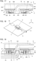
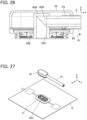
- FIGS. 27 and 28 show a connector assembly according to Embodiment 3 in the non-fitted state.
- the connector assembly includes a first connector 71 to be mounted on the mounting object C and a second connector 81 to be attached to the -Y directional tip of the fluid distribution tube P1, and the first connector 71 includes a passage connection port accommodation portion 73C, and the second connector 81 includes a passage connection port 83B.
- the first connector 71 includes a first bottom insulator 73 and a first top insulator 74 each made of an insulating resin.
- the first bottom insulator 73 includes a flat plate portion 73A extending along an XY plane, and at a center portion of the flat plate portion 73A, the passage connection port accommodation portion 73C of recess shape is integrally formed to extend in the Z direction and penetrate the first bottom insulator 73.
- a cylindrical shaped portion 73B is formed to project from the first bottom insulator 73 in the -Z direction, and an opening end portion on the -Z direction side of the cylindrical shaped portion 73B constitutes the first distribution port R1 opening toward an outside of the first connector 71.
- the first bottom insulator 73 has the same configuration as that of the first bottom insulator 13 in the first connector 11 of Embodiment 1 except that, in place of the passage connection port 13B, the passage connection port accommodation portion 73C is provided, while the first top insulator 74 has the same configuration as that of the first top insulator 14 in the first connector 11 of Embodiment 1.
- the pair of first contact members 15 are attached to the first bottom insulator 73.
- the second connector 81 includes a second bottom insulator 83 and a second top insulator 84 each made of an insulating resin.
- the passage connection port 83B of cylindrical shape is integrally formed to extend in the -Z direction, and the passage connection port 83B is provided in its interior with a linking passage 83C extending in the Z direction and penetrating the second bottom insulator 83.
- the second bottom insulator 83 has the same configuration as that of the second bottom insulator 23 in the second connector 21 of Embodiment 1 except that, in place of the passage connection port accommodation portion 23C, the passage connection port 83B is provided, while the second top insulator 84 has the same configuration as that of the second top insulator 24 in the second connector 21 of Embodiment 1.
- the pair of second contact members 25 are attached to the second bottom insulator 83.
- the tip of the fluid distribution tube P1 bent toward the -Z direction is fixed to the +Z directional end portion of the passage connection port 83B of the second bottom insulator 83 of the second connector 81.
- the tip of the fluid distribution tube P1 is bonded to the passage connection port 83B by use of an adhesive, for example.
- an end portion of the mounting object-side distribution tube P4 is inserted from the -Z direction in the passage connection port accommodation portion 73C of the first bottom insulator 73 of the first connector 71, whereby the mounting object-side distribution tube P4 is joined to the first distribution port R1 opening toward the outside of the first connector 71.
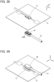
- the second connector 81 is pressed from the +Z direction toward the first connector 71, the passage connection port 83B of the second connector 81 is thus accommodated in the passage connection port accommodation portion 73C of the first connector 71, and, as a result, the fluid distribution tube P1 communicates with the mounting object-side distribution tube P4 via the linking passage 83C of the passage connection port 83B. Accordingly, with use of a pump or another device (not shown), a fluid such as air or water can be supplied to the mounting object-side distribution tube P4 via the fluid distribution tube P1, or a fluid can be sucked into the fluid distribution tube P1 via the mounting object-side distribution tube P4.
- the pair of first contact members 15 of the first connector 71 make contact with the pair of second contact members 25 of the second connector 81 to establish electrical conduction therebetween.
- the passage connection port accommodation portion 73C is integrally formed in the first bottom insulator 73 made of an insulating resin while the passage connection port 83B is integrally formed in the second bottom insulator 83 made of an insulating resin, the manufacturing process of the connector assembly is simplified, whereby the connector assembly can be easily manufactured.
- the connector assembly can be configured such that the second connector 81 includes the bent tube portion 63A used in Embodiment 2, and the fluid distribution tube P3 is fixed to an end portion of the bent tube portion 63A.
- the mounting object C includes the pair of wiring portions C3 and the pair of electrodes C4 formed of embroidery using embroidery threads made of a conductive thread; however, the connector assembly can be also configured such that a wiring portion and an electrode each having a conductive layer formed on a surface of an insulating resin film by printing or another method are attached to a surface of the mounting object C.
- a pressure sensor or other various sensors may be connected to the wiring portion C3 in place of the electrode C4.
- the pair of first contact members 15 and the pair of second contact members 25 are used; however, it suffices if at least one first contact member 15 and at least one second contact member 25 are provided, and the number of the first contact members 15 or of the second contact members 25 is not limited.
Landscapes
- Health & Medical Sciences (AREA)
- Life Sciences & Earth Sciences (AREA)
- Cardiology (AREA)
- Heart & Thoracic Surgery (AREA)
- Molecular Biology (AREA)
- Veterinary Medicine (AREA)
- Biophysics (AREA)
- Pathology (AREA)
- Engineering & Computer Science (AREA)
- Biomedical Technology (AREA)
- Public Health (AREA)
- Medical Informatics (AREA)
- Physics & Mathematics (AREA)
- Surgery (AREA)
- Animal Behavior & Ethology (AREA)
- General Health & Medical Sciences (AREA)
- Physiology (AREA)
- Vascular Medicine (AREA)
- Pulmonology (AREA)
- Connector Housings Or Holding Contact Members (AREA)
- Coupling Device And Connection With Printed Circuit (AREA)
Abstract
Description
- The present invention relates to a connector assembly and a connector, particularly to a connector assembly in which a second connector that is attached to a tip of a fluid distribution tube is fitted, along a fitting direction, to a first connector that is mounted on a flexible mounting object.
- In recent years, attention has been drawn to so-called smart clothes that can obtain user's biological data such as the heart rate and the body temperature only by being worn by the user. Such smart clothes have an electrode disposed at a measurement site, and when a wearable device serving as a measurement device is electrically connected to the electrode, biological data can be transmitted to the wearable device.
- The electrode and the wearable device can be interconnected by, for instance, use of a connector for garments that is mounted on a garment as smart clothes.
- Moreover, for instance, when electrocardiogram, blood pressure or the like is measured, for the sake of reducing the user's load, it is desired to blow air onto a user's body surface under compression by an electrode. However, the connector for garments as described above has difficulty in distributing a fluid such as air although the connector is capable of electric connection.
- For example,
WO 2016/132879 discloses a connecting device that performs connection of a fluid passage for distributing air, liquids, or the like and electric connection between a subject and a measurement apparatus at a time. The connecting device includes a living body-side connector 1 and a measurement apparatus-side connector 2 as shown inFIG. 31 . - The living body-side connector 1 includes a
housing 1A, a plurality ofconnection terminals 1B held by thehousing 1A and attached to an end portion of a living body-side cable 3, and aconnection port 1C held by thehousing 1A and connected to an end portion of a living body-side tube 4. Meanwhile, the measurement apparatus-side connector 2 includes ahousing 2A, a plurality ofconnection terminals 2B held by thehousing 2A and attached to an end portion of the measurement apparatus-side cable 5, and aconnection port 2C held by thehousing 2A and connected to an end portion of a measurement apparatus-side tube 6. - As shown in
FIG. 32 , theconnection port 1C of the living body-side connector 1 is composed of a rear end-side nozzle portion 1D joined to the end portion of the living body-side tube 4 and a tip end-side nozzle portion 1E joined to the rear end-side nozzle portion 1D with a tube joint and attached to thehousing 1A, and theconnection port 2C of the measurement apparatus-side connector 2 is composed of a rear end-side nozzle portion 2D joined to the end portion of the measurement apparatus-side tube 6 and a tip end-side nozzle portion 2E joined to the rear end-side nozzle portion 2D with a tube joint and attached to thehousing 2A. - By use of such a connecting device, electric connection between the living body-
side cable 3 and the measurement apparatus-side cable 5 and connection of a fluid passage between the living body-side tube 4 and the measurement apparatus-side tube 6 can be made at a time. - However, it is difficult to mount the connecting device of
WO 2016/132879 on a flexible mounting object such as garments, disadvantageously. - In addition, for producing the
connection port 1C of the living body-side connector 1, it is necessary to attach the tip end-side nozzle portion 1E to thehousing 1A and join the rear end-side nozzle portion 1D to the tip end-side nozzle portion 1E with a tube joint, and similarly, for producing theconnection port 2C of the measurement apparatus-side connector 2, it is necessary to attach the tip end-side nozzle portion 2E to thehousing 2A and join the rear end-side nozzle portion 2D to the tip end-side nozzle portion 2E with a tube joint, resulting in complicated production process of the connecting device, disadvantageously. - The present invention has been made in order to solve the conventional problems described above and aims at providing a connector assembly and a connector that can be mounted on a flexible mounting object and can perform electric connection and connection of a fluid passage at a time while easy production thereof is possible.
- The connector assembly according to the present invention is a connector assembly in which a second connector is fitted to a first connector along a fitting direction, the second connector being attached to a tip of a fluid distribution tube, and the first connector being mounted on a mounting object that is flexible and is provided with a wiring portion,
wherein the first connector includes: - a first housing that is configured to be attached to the mounting object, includes a first distribution port opening toward an outside of the first connector, and is made of an insulating resin; and
- a first contact member that is conductive and is configured to be held by the first housing and electrically connected to the wiring portion,
- the second connector includes:
- a second housing that is configured to be attached to the tip of the fluid distribution tube, opposes the first housing, and is made of an insulating resin; and
- a second contact member that is conductive, is held by the second housing, and corresponds to the first contact member,
- a passage connection port of tubular shape is integrally formed in one of the first housing and the second housing, the passage connection port extending along the fitting direction and including in its interior a linking passage extending along the fitting direction,
- a passage connection port accommodation portion of recess shape is integrally formed in another one of the first housing and the second housing, the passage connection port accommodation portion extending along the fitting direction and being configured to accommodate the passage connection port, and
- when the second connector is fitted with the first connector, the first contact member is electrically connected to the second contact member, and the passage connection port is accommodated in the passage connection port accommodation portion whereby the first distribution port communicates with the fluid distribution tube via the linking passage.
- The connector according to the present invention is a connector which is mounted on a mounting object and to which a counter connector is fitted along a fitting direction, the mounting object being flexible and being provided with a wiring portion, the connector comprising:
- a housing that is configured to be attached to the mounting object, includes a distribution port opening toward an outside of the connector, and is made of an insulating resin, and
- a contact member that is conductive and is held by the housing and is configured to be electrically connected to the wiring portion,
- wherein a passage connection port of tubular shape is integrally formed in the housing, the passage connection port extending along the fitting direction and including in its interior a linking passage extending along the fitting direction, and
- when the counter connector is fitted with the connector, the contact member is electrically connected to a counter contact member of the counter connector, and the passage connection port is accommodated in a passage connection port accommodation portion of the counter connector whereby the distribution port communicates, via the linking passage, with a fluid distribution tube attached to the counter connector.
-
-
FIG. 1 is a perspective view showing a connector assembly according to Embodiment 1 in the non-fitted state, when viewed from an obliquely upper position. -
FIG. 2 is a perspective view showing the connector assembly according to Embodiment 1 in the non-fitted state, when viewed from an obliquely lower position. -
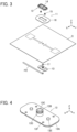
FIG. 3 is an assembly view of a first connector in Embodiment 1. -
FIG. 4 is a perspective view showing a first bottom insulator used in the first connector in Embodiment 1. -
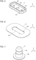
FIG. 5 is a perspective view showing a first top insulator used in the first connector in Embodiment 1. -
FIG. 6 is a perspective view showing a reinforcement sheet used in the first connector in Embodiment 1. -
FIG. 7 is a perspective view showing a first contact member used in the first connector in Embodiment 1. -
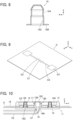
FIG. 8 is a cross-sectional view showing the first contact member used in the first connector in Embodiment 1. -
FIG. 9 is a perspective view showing a mounting object on which the first connector is mounted in Embodiment 1. -
FIG. 10 is a cross-sectional view showing the first connector in Embodiment 1 which is mounted on the mounting object and to which a mounting object-side distribution tube is attached. -
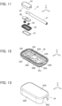
FIG. 11 is an assembly view of a second connector in Embodiment 1. -
FIG. 12 is a perspective view showing a second bottom insulator used in the second connector in Embodiment 1. -
FIG. 13 is a perspective view showing a second top insulator used in the second connector in Embodiment 1. -
FIG. 14 is a perspective view showing a second contact member used in the second connector in Embodiment 1. -
FIG. 15 is a perspective view showing a circuit board used in the second connector in Embodiment 1. -
FIG. 16 is a perspective view showing a fluid distribution tube to which the second connector is attached in Embodiment 1. -
FIG. 17 is a cross-sectional view showing the second connector in Embodiment 1 attached to the fluid distribution tube. -
FIG. 18 is a perspective view showing the connector assembly according to Embodiment 1 in the fitted state. -
FIG. 19 is a cross-sectional view showing the connector assembly according to Embodiment 1 in the fitted state. -
FIG. 20 is a cross-sectional view showing a first connector in Modification 1 of Embodiment 1. -
FIG. 21 is a cross-sectional view showing a first connector inModification 2 of Embodiment 1. -
FIG. 22 is a cross-sectional view showing a first connector inModification 3 of Embodiment 1. -
FIG. 23 is an assembly view of a second connector in a connector assembly ofEmbodiment 2. -
FIG. 24 is a perspective view showing a second bottom insulator used in the second connector inEmbodiment 2. -
FIG. 25 is a perspective view showing a fluid distribution tube to which the second connector is attached inEmbodiment 2. -
FIG. 26 is a cross-sectional view showing the second connector inEmbodiment 2 attached to the fluid distribution tube. -
FIG. 27 is a perspective view showing a connector assembly according toEmbodiment 3 in the non-fitted state, when viewed from an obliquely upper position. -
FIG. 28 is a perspective view showing the connector assembly according toEmbodiment 3 in the non-fitted state, when viewed from an obliquely lower position. -
FIG. 29 is a perspective view showing the connector assembly according toEmbodiment 3 in the fitted state. -
FIG. 30 is a cross-sectional view showing the connector assembly according toEmbodiment 3 in the fitted state. -
FIG. 31 is a perspective view showing a living body-side connector and a measurement apparatus-side connector in a conventional connecting device. -
FIG. 32 is a cross-sectional view showing the structure of connection ports of the living body-side connector and the measurement apparatus-side connector in the conventional connecting device. - Embodiments of the present invention are described below based on the accompanying drawings.
-
FIGS. 1 and 2 show a connector assembly according to Embodiment 1 in the non-fitted state. The connector assembly is composed of a first connector (connector) 11 and a second connector (counter connector) 21 to be fitted to each other along a fitting direction. Thefirst connector 11 includes a first housing (housing) 12 mounted on a flexible mounting object C such as fabric of a garment, for example, and thesecond connector 21 includes asecond housing 22 attached to a tip of a fluid distribution tube P1. - For convenience, the mounting object C is defined as extending along an XY plane, the direction in which the fluid distribution tube P1 extends is referred to as "Y direction," and the direction from the
first connector 11 to thesecond connector 21 is referred to as "+Z direction." The Z direction is the fitting direction in which thefirst connector 11 and thesecond connector 21 are fitted together. - The
second connector 21 is disposed on the +Z direction side of the mounting object C, and a mounting object-side distribution tube P2 is joined to thefirst housing 12 of thefirst connector 11 on the -Z direction side of the mounting object C. -
FIG. 3 shows an assembly view of thefirst connector 11. Thefirst housing 12 is made of an insulating resin and is formed of a firstbottom insulator 13 disposed on the - Z direction side of the mounting object C, and a firsttop insulator 14 disposed on the +Z direction side of the mounting object C. - A pair of first contact members (contact members) 15 are disposed on the -Z direction side of the first
top insulator 14, areinforcement sheet 16 is disposed on the -Z direction side of the pair offirst contact members 15, and the mounting object C is disposed on the -Z direction side of thereinforcement sheet 16. Furthermore, the firstbottom insulator 13 is disposed on the -Z direction side of the mounting object C via an O-ring 17, and the mounting object-side distribution tube P2 is disposed on the -Z direction side of the firstbottom insulator 13. - As shown in
FIG. 4 , the firstbottom insulator 13 includes aflat plate portion 13A extending along an XY plane, and, at a center portion of theflat plate portion 13A, apassage connection port 13B of cylindrical shape is integrally formed to extend from the +Z directional surface of theflat plate portion 13A in the +Z direction. Thepassage connection port 13B is provided in its interior with alinking passage 13C extending in the Z direction and penetrating the firstbottom insulator 13. Although not shown inFIG. 4 , thelinking passage 13C penetrates the firstbottom insulator 13, whereby an opening end portion of thelinking passage 13C constitutes a first distribution port R1 opening toward an outside of thefirst connector 11 in the -Z directional surface of theflat plate portion 13A. - At an outer peripheral portion of the
passage connection port 13B, anannual groove 13D is formed along an XY plane to surround thepassage connection port 13B. - The +Z directional surface of the
flat plate portion 13A is provided with a pair ofprojections 13E projecting in the +Z direction and formed on opposite sides of thepassage connection port 13B in the Y direction across thepassage connection port 13B. - In addition, a plurality of through-
holes 13F are formed in the vicinity of a peripheral edge portion of theflat plate portion 13A. - As shown in
FIG. 5 , the firsttop insulator 14 includes a recessed secondconnector accommodation portion 14A opening in the +Z direction, and, at a center portion of the secondconnector accommodation portion 14A, a connection port through-hole 14B is formed to penetrate the firsttop insulator 14 in the Z direction. In the secondconnector accommodation portion 14A, a pair of contact through-holes 14C are also formed on opposite sides of the connection port throughhole 14B in the Y direction across the connection port through-hole 14B to penetrate the firsttop insulator 14 in the Z direction. - In addition, at a peripheral portion of a surface, facing in the -Z direction, of the first
top insulator 14, a plurality ofbosses 14D are formed to project in the -Z direction. The plurality ofbosses 14D separately correspond to the plurality of through-holes 13F of the firstbottom insulator 13. - As shown in
FIG. 6 , thereinforcement sheet 16 is used to reinforce the mounting object C on which thefirst connector 11 is mounted. Thereinforcement sheet 16 is made of an insulating material and provided at its center with anopening portion 16A. Further, a plurality ofcutouts 16B separately corresponding to the plurality ofbosses 14D of the firsttop insulator 14 are formed along the periphery of theopening portion 16A of thereinforcement sheet 16. - As shown in
FIG. 7 , thefirst contact member 15 is made of an electrically conductive material such as metal and includes: atubular portion 15A of cylindrical shape projecting in the +Z direction; and aflange 15B of disc shape extending in a radial direction along an XY plane from the outer periphery of a -Z directional end portion of thetubular portion 15A. - As shown in
FIG. 8 , thetubular portion 15A is provided in its interior with a recessedportion 15C opening in the -Z direction. - As shown in
FIG. 9 , the mounting object C is formed of, for example, fabric of a garment, and is provided with a single through-hole C1 through which thepassage connection port 13B of the firstbottom insulator 13 passes, and a plurality of through-holes C2 disposed around the through-hole C1 and corresponding to the plurality ofbosses 14D of the firsttop insulator 14. - The mounting object C is also provided with a pair of wiring portions C3 and a pair of electrodes C4 formed of, for example, embroidery using embroidery threads made of a conductive thread. The pair of wiring portions C3 separately extend in the +Y direction and the -Y direction form the vicinity of the through-hole C1 and are connected to the corresponding electrodes C4.
- When the
first connector 11 is assembled, first, thetubular portion 15A of thefirst contact member 15 is inserted to the corresponding one of the pair of contact through-holes 14C of the firsttop insulator 14 from the -Z direction, and the plurality ofbosses 14D of the firsttop insulator 14 are sequentially inserted to the plurality ofcutouts 16B of thereinforcement sheet 16 and the plurality of through-holes C2 of the mounting object C. In this process, the pair offirst contact members 15 are situated within theopening portion 16A of thereinforcement sheet 16, and the connection port through-hole 14B of the firsttop insulator 14 is situated at a position overlapping the through-hole C1 of the mounting object C on the +Z direction side. - Subsequently, the O-
ring 17 is fitted into theannular groove 13D of thepassage connection port 13B of the firstbottom insulator 13, and the firstbottom insulator 13 is pressed from the -Z direction side of the mounting object C toward the firsttop insulator 14, with the mounting object C being held therebetween. In this process, as shown inFIG. 10 , thepassage connection port 13B of the firstbottom insulator 13 passes through the through-hole C1 of the mounting object C and the connection port through-hole 14B of the firsttop insulator 14 to project in the secondconnector accommodation portion 14A of the firsttop insulator 14, and the pair ofprojections 13E of the firstbottom insulator 13 are separately inserted into the recessedportions 15C of the correspondingfirst contact members 15 while pushing the pair of wiring portions C3 of the mounting object C therein. - Accordingly, the wiring portion C3 of the mounting object C pushed into the recessed
portion 15C of thefirst contact member 15 is held between a lateral surface of theprojection 13E of the firstbottom insulator 13 and an inner surface of the recessedportion 15C of thefirst contact member 15 and is electrically connected to thefirst contact member 15. - In addition, by pressing the first
bottom insulator 13 toward the firsttop insulator 14, thebosses 14D of the firsttop insulator 14 sequentially passing through thecutouts 16B of thereinforcement sheet 16 and the through-holes C2 of the mounting object C pass through the through-holes 13F of the firstbottom insulator 13. Thereafter, tips of thebosses 14D projecting on the -Z direction side of the firstbottom insulator 13 are thermally deformed, whereby the firstbottom insulator 13 and the firsttop insulator 14 are fixed to each other, and the assembling of thefirst connector 11 is completed while thefirst connector 11 is mounted on the mounting object C. - In order to reinforce the mounting object C, the
reinforcement sheet 16 extending to the outside of the firstbottom insulator 13 and the firsttop insulator 14 is preferably fixed to the mounting object C by sewing or other means. - Moreover, as shown in
FIG. 10 , the end portion of the mounting object side-distribution tube P2 is inserted from the -Z direction into thelinking passage 13C formed in the interior of thepassage connection port 13B of the firstbottom insulator 13, whereby the mounting object-side distribution tube P2 is joined to the first distribution port R1 that is formed of the opening end portion on the -Z direction side of thelinking passage 13C and is opening toward the outside of thefirst connector 11. -
FIG. 11 shows an assembly view of thesecond connector 21. Thesecond housing 22 is made of an insulating resin and is formed of a secondbottom insulator 23 and a secondtop insulator 24. - The fluid distribution tube P1 is disposed on the -Z direction side of the second
top insulator 24, acircuit board 26 is disposed on the -Z direction side of the fluid distribution tube P1, a pair of second contact members (counter contact members) 25 are disposed on the -Z direction side of thecircuit board 26, the secondbottom insulator 23 is disposed on the -Z direction side of the pair ofsecond contact members 25, and awaterproof member 27 is disposed on the -Z direction side of the secondbottom insulator 23. - As shown in
FIG. 12 , the secondbottom insulator 23 includes aflat plate portion 23A extending along an XY plane; at a center portion of theflat plate portion 23A, a cylindrical shapedportion 23B is formed to project and extend from the +Z directional surface of theflat plate portion 23A in the +Z direction, and, in the interior of the cylindrical shapedportion 23B, a passage connectionport accommodation portion 23C of cylindrical shape is integrally formed to extend in the Z direction and penetrate the secondbottom insulator 23. - The second
bottom insulator 23 also includes aprotrusion portion 23D projecting from theflat plate portion 23A in the -Z direction, and a pair of recessedcontact accommodation portions 23E are formed inside theprotrusion portion 23D, the pair ofcontact accommodation portions 23E opening in the +Z direction and being situated on opposite sides of the cylindrical shapedportion 23B in the Y direction across the cylindrical shapedportion 23B. In a bottom portion of each of thecontact accommodation portions 23E, a through-hole 23F is formed. - The
flat plate portion 23A is provided, on the -Y direction side of the cylindrical shapedportion 23B, with a pair ofpositioning pins 23G disposed to be separated from each other in the X direction and projecting in the +Z direction. - At a peripheral portion of the
flat plate portion 23A, aperipheral wall portion 23H is formed to project in the +Z direction, and at an outer peripheral portion of theprotrusion portion 23D, acircumferential groove 23J is disposed to surround theprotrusion portion 23D along an XY plane. - In addition, a
cutout 23K in which part of the fluid distribution tube P1 is inserted is formed at the +Y directional end portion of thecircumferential wall portion 23H of the secondbottom insulator 23. - As shown in
FIG. 13 , the secondtop insulator 24 includes atop plate portion 24A extending along an XY plane, and, at a peripheral portion of thetop plate portion 24A, acircumferential wall portion 24B is formed to project in the -Z direction. With thetop plate portion 24A and thecircumferential wall portion 24B, the secondtop insulator 24 has a box-like shape opening in the -Z direction. - In addition, a
cutout 24C through which the fluid distribution tube P1 passes is formed at the +Y directional end portion of thecircumferential wall portion 24B of the secondtop insulator 24. - As shown in
FIG. 14 , thesecond contact member 25 is made of, for example, a conductive metal sheet, and includes abase portion 25A extending along an XY plane. Thebase portion 25A is provided with a through-hole 25B through which thetubular portion 15A of the correspondingfirst contact member 15 of thefirst contact 11 passes when thefirst connector 11 and thesecond connector 21 are fitted with each other. - A pair of
contact portions 25C are joined to thebase portion 25A, thecontact portions 25C making elastic contact with thetubular portion 15A of thefirst contact member 15. Moreover, thesecond contact member 25 is provided with fixingportions 25D facing in the +Z direction. - As shown in
FIG. 15 , thecircuit board 26 has a flat plate shape, and at a center portion of thecircuit board 26, a through-hole 26A through which the tip of the fluid distribution tube P1 passes is formed. - A
connection pad 26B is disposed on the +Y direction side of the through-hole 26A on the +Z directional surface of thecircuit board 26, and also on the -Z directional surface of thecircuit board 26, disposed is a connection pad (not shown) electrically connected to theconnection pad 26B. - The
circuit board 26 is further provided, on the -Y direction side of the through-hole 26A, with a pair ofpositioning holes 26C disposed to be separated from each other in the X direction and penetrating thecircuit board 26 in the Z direction. - As shown in
FIG. 16 , the fluid distribution tube P1 is covered by a casing S; in the casing S, the fluid distribution tube P1 for distributing air, water or another fluid and an electric wire W for transmitting an electric signal are accommodated, thereby configuring a so-called composite cable. - By removing part of the casing S over a predetermined length in the vicinity of the -Y directional end portion of the fluid distribution tube P1, the fluid distribution tube P1 is exposed from the casing S, and the electric wire W is also exposed while not shown in the drawings.
- The -Y directional tip of the fluid distribution tube P1 exposed from the casing S is bent toward the -Z direction.
- When the
second connector 21 is assembled, first, the pair ofsecond contact members 25 are attached to thecircuit board 26. In this process, the fixingportions 25D of eachsecond contact member 25 are fixed to connection pads (not shown) disposed on the -Z directional surface of thecircuit board 26 by soldering or another means. - Subsequently, with the pair of positioning pins 23G of the second
bottom insulator 23 being passed through the pair ofpositioning holes 26C of thecircuit board 26, thecircuit board 26 is disposed inside thecircumferential wall portion 23H of the secondbottom insulator 23. With this constitution, as shown inFIG. 17 , the pair ofsecond contact members 25 fixed to thecircuit board 26 are accommodated in the pair of recessedcontact accommodation portions 23E of the secondbottom insulator 23, and the through-hole 25B of eachsecond contact member 25 is situated at a position overlapping the through-hole 23F of the correspondingcontact accommodation portion 23E on the +Z direction side. - In this state, the fluid distribution tube P1 is disposed on the +Z direction side of the second
bottom insulator 23, and the -Y directional tip of the fluid distribution tube P1 being bent from the Y direction toward the -Z direction is inserted into the passage connectionport accommodation portion 23C of the secondbottom insulator 23 and fixed therein. By use of an adhesive, for example, the tip of the fluid distribution tube P1 can be bonded to an inner surface of the cylindrical shapedportion 23B. - In addition, the electric wire W exposed from the casing S in the vicinity of the - Y directional end portion of the fluid distribution tube P1 is connected to the
connection pad 26B of thecircuit board 26 by soldering or another means, whereby the pair ofsecond contact members 25 are electrically connected to the electric wire W. - Thereafter, the second
top insulator 24 is disposed on the +Z direction side of the secondbottom insulator 23, and thecircumferential wall portion 23H of the secondbottom insulator 23 and thecircumferential wall portion 24B of the secondtop insulator 24 are bonded together in abutment with each other in the Z direction, whereby the secondtop insulator 24 is fixed to the secondbottom insulator 23. Moreover, thewaterproof member 27 is fitted in thecircumferential groove 23J of theprotrusion portion 23D of the secondbottom insulator 23. The assembling operation of thesecond connector 21 is thus completed. - It should be noted that the fluid distribution tube P1 extends from the
second connector 21 in the +Y direction through thecutout 23K of the secondbottom insulator 23 and thecutout 24C of the secondtop insulator 24. - As shown in
FIG. 18 , by pressing thesecond connector 21 from the +Z direction toward thefirst connector 11 mounted on the mounting object C, thesecond connector 21 is fitted with thefirst connector 11, and the connector assembly according to Embodiment 1 is assembled. - At this time, as shown in
FIG. 19 , theprotrusion portion 23D of the secondbottom insulator 23 of thesecond connector 21 is inserted in the secondconnector accommodation portion 14A of the firsttop insulator 14 of thefirst connector 11, and thepassage connection port 13B of thefirst connector 11 is accommodated in the passage connectionport accommodation portion 23C of thesecond connector 21. - As a result, the fluid distribution tube P1 having its tip inserted in the passage connection
port accommodation portion 23C communicates with the first distribution port R1 of thefirst connector 11 via thelinking passage 13C of thepassage connection port 13B; since the mounting object-side distribution tube P2 is joined to the first distribution port R1, the fluid distribution tube P1 and the mounting object-side distribution tube P2 communicate with each other. Accordingly, with use of a pump or another device (not shown), a fluid such as air or water can be supplied to the mounting object-side distribution tube P2 via the fluid distribution tube P1, or a fluid can be sucked into the fluid distribution tube P1 via the mounting object-side distribution tube P2. - In addition, by pressing the
second connector 21 toward thefirst connector 11, the pair offirst contact members 15 of thefirst connector 11 make contact with the pair ofsecond contact members 25 of thesecond connector 21 to establish electrical conduction therebetween. Since thefirst contact member 15 is connected to the wiring portion C3 of the mounting object C and thesecond contact member 25 is connected to the electric wire W, when thefirst contact member 15 and thesecond contact member 25 establish electrical conduction therebetween, the wiring portion C3 of the mounting object C is electrically connected to the electric wire W. In addition, since the electrode C4 is connected to the wiring portion C3 in the mounting object C, the electrode C4 is electrically connected to the electric wire W via the wiring portion C3, thefirst contact member 15, and thesecond contact member 25. - Therefore, when fabric of smart clothes is adopted as the mounting object C, biological information of a user obtained by the electrode C4 can be transmitted to, for example, a measurement device via the electric wire W.
- As described above, according to Embodiment 1, by merely fitting the
second connector 21 with thefirst connector 11, electrical connection and connection of a fluid passage can be established at a time, thus realizing a connector assembly with high utility. - In addition, since the
passage connection port 13B for connection of a fluid passage is integrally formed in the firstbottom insulator 13 made of an insulating resin while the passage connectionport accommodation portion 23C is integrally formed in the secondbottom insulator 23 made of an insulating resin, the manufacturing process of the connector assembly is simplified, whereby the connector assembly can be easily manufactured. - It should be noted that fabric of a garment such as smart clothes can be adopted as the mounting object C, and the connector assembly can be also configured to supply a fluid such as air or water to a user's body surface or suck out sweat, urine, or the like from the user's side by having the fluid distribution tube P1 and the mounting object-side distribution tube P2 communicating with each other.
- Since the O-
ring 17 is disposed at the outer peripheral portion of thepassage connection port 13B, a space between an inner peripheral surface of the passage connectionport accommodation portion 23C and an outer peripheral surface of thepassage connection port 13B is sealed, and since thewaterproof member 27 is disposed at the outer peripheral portion of theprotrusion portion 23D of the secondbottom insulator 23, a space between an inner peripheral surface of the secondconnector accommodation portion 14A of the firsttop insulator 14 and an outer peripheral surface of theprotrusion portion 23D of the secondbottom insulator 23 is sealed. - In the
first connector 11 according to Embodiment 1 described above, thepassage connection port 13B is integrally formed in the firstbottom insulator 13, but the present invention is not limited to the case. -
FIG. 20 shows afirst connector 31 in Modification 1 of Embodiment 1. Thefirst connector 31 includes a firstbottom insulator 33 and a firsttop insulator 34 each made of an insulating resin, and apassage connection port 34B is integrally formed in the firsttop insulator 34. - The first
top insulator 34 includes a recessed secondconnector accommodation portion 34A opening in the +Z direction; at a center portion of the secondconnector accommodation portion 34A, thepassage connection port 34B is formed to project in the +Z direction, and in the interior of thepassage connection port 34B, alinking passage 34C is formed to penetrate the firsttop insulator 34 in the Z direction. - In the first
bottom insulator 33, anopening portion 33G is formed to communicate with thelinking passage 34C on the -Z direction side thereof, theopening portion 33G and thelinking passage 34C having the same inside diameter, and an opening end portion on the -Z direction side of theopening portion 33G constitutes the first distribution port R1 opening toward an outside of thefirst connector 31. - The first
bottom insulator 33 and the firsttop insulator 34 respectively have the same configurations as those of the firstbottom insulator 13 and the firsttop insulator 14 of thefirst connector 11 in Embodiment 1 except that, in place of thepassage connection port 13B being formed in the firstbottom insulator 13, thepassage connection port 34B is formed in the firsttop insulator 34, and theopening portion 33G is formed in the firstbottom insulator 33. - Even when the
first connector 31 configured as above is used in place of thefirst connector 11, by merely fitting thesecond connector 21 with thefirst connector 31, electrical connection and connection of a fluid passage can be established at a time as with Embodiment 1. -
FIG. 21 shows afirst connector 41 inModification 2 of Embodiment 1. Thefirst connector 41 includes a firstbottom insulator 43 and a firsttop insulator 44 each made of an insulating resin, and apassage connection port 44B is integrally formed in the firsttop insulator 44. - The first
top insulator 44 includes a recessed secondconnector accommodation portion 44A opening in the +Z direction, and, at a center portion of the secondconnector accommodation portion 44A, apassage connection port 44B is formed to project in the +Z direction. - In addition, on the -Z direction side of the
passage connection port 44B, a cylindrical shapedportion 44E is formed to project in the -Z direction from the firsttop insulator 44, and in the interiors of thepassage connection port 44B and the cylindrical shapedportion 44E, alinking passage 44C is formed to penetrate the firsttop insulator 44 in the Z direction. - The cylindrical shaped
portion 44E of the firsttop insulator 44 is inserted in anopening portion 43G formed in the firstbottom insulator 43, and an end surface of the cylindrical shapedportion 44E facing in the -Z direction is exposed on the -Z direction side of the firstbottom insulator 43. In other words, thelinking passage 44C penetrates thefirst connector 41 in the Z direction, and an opening end portion on the -Z direction side of the cylindrical shapedportion 44E constitutes the first distribution port R1 opening toward an outside of thefirst connector 41. - The first
bottom insulator 43 and the firsttop insulator 44 respectively have the same configurations as those of the firstbottom insulator 13 and the firsttop insulator 14 of thefirst connector 11 in Embodiment 1 except that, in place of thepassage connection port 13B being formed in the firstbottom insulator 13, thepassage connection port 44B and the cylindrical shapedportion 44E are formed in the firsttop insulator 44, and theopening portion 43G is formed in the firstbottom insulator 43. - Even when the
first connector 41 configured as above is used in place of thefirst connector 11, by merely fitting thesecond connector 21 with thefirst connector 41, electrical connection and connection of a fluid passage can be established at a time as with Embodiment 1. -
FIG. 22 shows afirst connector 51 inModification 3 of Embodiment 1. Thefirst connector 51 includes a firstbottom insulator 53 and the firsttop insulator 14 each made of an insulating resin, and apassage connection port 53B is integrally formed in the firstbottom insulator 53. The firsttop insulator 14 is the same as the firsttop insulator 14 in thefirst connector 11 of Embodiment 1. - The
passage connection port 53B penetrates the connection port through-hole 14B of the firsttop insulator 14 to project in the +Z direction from the secondconnector accommodation portion 14A of the firsttop insulator 14. - While in the interior of the
passage connection port 53B, alinking passage 53C is formed to extend in the -Z direction from the +Z directional end portion of thepassage connection port 53B, thelinking passage 53C does not penetrate the firstbottom insulator 53 in the Z direction but communicates with afirst passage 53G extending inside the firstbottom insulator 53 in the Y direction. - The
first passage 53G is opened at the -Y directional end portion of the firstbottom insulator 53, and an opening end portion of thefirst passage 53G constitutes the first distribution port R1 opening toward an outside of thefirst connector 51. - Although not shown in the drawings, the mounting object-side distribution tube P2 as used in Embodiment 1 can be joined to the first distribution port R1.
- The first
bottom insulator 53 has the same configuration as that of the firstbottom insulator 13 in thefirst connector 11 of Embodiment 1 except that, in place of thepassage connection port 13B and thelinking passage 13C, thepassage connection port 53B, thelinking passage 53C, and thefirst passage 53G are formed. - Even when the
first connector 51 configured as above is used in place of thefirst connector 11, by merely fitting thesecond connector 21 with thefirst connector 51, electrical connection and connection of a fluid passage can be established at a time as with Embodiment 1. - In addition, it is possible that in the first
bottom insulator 53, a plurality offirst passages 53G are formed to each communicate with thelinking passage 53C, and a plurality of first distribution ports R1 are formed to correspond to the plurality offirst passages 53G. With this constitution, for instance, a fluid such as air or water can be supplied through the fluid distribution tube P1 and distributed from the first distribution ports R1. - Moreover, the
linking passage 53C may be formed to penetrate the firstbottom insulator 53 in the Z direction while thefirst passage 53G extending inside the firstbottom insulator 53 in the Y direction communicates with thelinking passage 53C. -
FIG. 23 shows an assembly view of asecond connector 61 used in a connector assembly according toEmbodiment 2. - A fluid distribution tube P3 is disposed on the -Z direction side of the second
top insulator 24, thecircuit board 26 is disposed on the -Z direction side of the fluid distribution tube P3, the pair ofsecond contact members 25 are disposed on the -Z direction side of thecircuit board 26, a secondbottom insulator 63 is disposed on the -Z direction side of the pair ofsecond contact members 25, and thewaterproof member 27 is disposed on the -Z direction side of the secondbottom insulator 63. - The second
top insulator 24, thecircuit board 26, thesecond contact member 25, and thewaterproof member 27 are the same members with the same reference numbers as those in thesecond connector 21 of Embodiment 1. - As shown in
FIG. 24 , the secondbottom insulator 63 is made of an insulating resin and includes abent tube portion 63A integrally formed on the +Z direction side of the cylindrical shapedportion 23B that is formed to project at a center portion of theflat plate portion 23A. In the interior of thebent tube portion 63A, formed is abent passage 63B that is bent such that one end thereof faces in the +Y direction orthogonal to the Z direction being the fitting direction, and the other end thereof faces in the -Z direction. - The second
bottom insulator 63 has the same configuration as that of the secondbottom insulator 23 in thesecond connector 21 of Embodiment 1 except that thebent tube portion 63A is provided. - As shown in
FIG. 25 , the fluid distribution tube P3 is covered by the casing S, and by removing part of the casing S over a predetermined length in the vicinity of the - Y directional end portion of the fluid distribution tube P3, the fluid distribution tube P3 is exposed from the casing S, and the -Y directional tip of the fluid distribution tube P3 is not bent but linearly extends in the -Y direction. - The fluid distribution tube P3 has the same configuration as that of the fluid distribution tube P1 used in Embodiment 1 except that the -Y directional tip thereof is not bent but linearly extends in the -Y direction.
- When the
second connector 61 is assembled, as with the assembly of thesecond connector 21 of Embodiment 1, thecircuit board 26 to which the pair ofsecond contact members 25 are attached is disposed inside the secondbottom insulator 63, and thereafter the -Y directional end portion of the fluid distribution tube P3 is fixed to an end portion, facing in the +Y direction, of thebent tube portion 63A of the secondbottom insulator 63 as shown inFIG. 26 . - As a result, the fluid distribution tube P3 communicates with the passage connection
port accommodation portion 23C formed in the interior of the cylindrical shapedportion 23B via thebent passage 63B of thebent tube portion 63A. - The -Y directional end portion of the fluid distribution tube P3 is inserted in the inside of the +Y directional end portion of the
bent tube portion 63A and bonded to an inner surface of thebent tube portion 63A by use of, for example, an adhesive. - In addition, the electric wire W exposed from the casing S of the fluid distribution tube P3 is connected to the
connection pad 26B of thecircuit board 26, and, furthermore, the secondtop insulator 24 is fixed on the +Z direction side of the secondbottom insulator 63, whereby the assembling operation of thesecond connector 61 is completed. - By fitting the
second connector 61 as above with thefirst connector 11 of Embodiment 1, the connector assembly according toEmbodiment 2 is assembled. As with Embodiment 1, by merely fitting thesecond connector 61 with thefirst connector 11, electrical connection and connection of a fluid passage can be established at a time, and since the passage connectionport accommodation portion 23C is integrally formed in the secondbottom insulator 63 made of an insulating resin, the connector assembly can be easily manufactured also inEmbodiment 2. - It should be noted that the
second connector 61 inEmbodiment 2 can be also fitted with any one of thefirst connectors 31 to 51 shown inFIGS. 20 to 22 , whereby the connector assembly can be assembled. - In Embodiment 1, the
first connector 11 to be mounted on the mounting object C includes thepassage connection port 13B, and thesecond connector 21 to be attached to the tip of the fluid distribution tube P1 includes the passage connectionport accommodation portion 23C, but the present invention is not limited to the case. -
FIGS. 27 and28 show a connector assembly according toEmbodiment 3 in the non-fitted state. The connector assembly includes afirst connector 71 to be mounted on the mounting object C and asecond connector 81 to be attached to the -Y directional tip of the fluid distribution tube P1, and thefirst connector 71 includes a passage connectionport accommodation portion 73C, and thesecond connector 81 includes apassage connection port 83B. - As shown in
FIG. 29 , by pressing thesecond connector 81 from the +Z direction toward thefirst connector 71, thesecond connector 81 is fitted with thefirst connector 71, and the connector assembly according toEmbodiment 3 is assembled. - As shown in
FIG. 30 , thefirst connector 71 includes a firstbottom insulator 73 and a firsttop insulator 74 each made of an insulating resin. The firstbottom insulator 73 includes aflat plate portion 73A extending along an XY plane, and at a center portion of theflat plate portion 73A, the passage connectionport accommodation portion 73C of recess shape is integrally formed to extend in the Z direction and penetrate the firstbottom insulator 73. On the -Z direction side of the passage connectionport accommodation portion 73C, a cylindrical shapedportion 73B is formed to project from the firstbottom insulator 73 in the -Z direction, and an opening end portion on the -Z direction side of the cylindrical shapedportion 73B constitutes the first distribution port R1 opening toward an outside of thefirst connector 71. - The first
bottom insulator 73 has the same configuration as that of the firstbottom insulator 13 in thefirst connector 11 of Embodiment 1 except that, in place of thepassage connection port 13B, the passage connectionport accommodation portion 73C is provided, while the firsttop insulator 74 has the same configuration as that of the firsttop insulator 14 in thefirst connector 11 of Embodiment 1. - In addition, the pair of
first contact members 15 are attached to the firstbottom insulator 73. - The
second connector 81 includes a secondbottom insulator 83 and a secondtop insulator 84 each made of an insulating resin. At a center portion of the secondbottom insulator 83, thepassage connection port 83B of cylindrical shape is integrally formed to extend in the -Z direction, and thepassage connection port 83B is provided in its interior with alinking passage 83C extending in the Z direction and penetrating the secondbottom insulator 83. - The second
bottom insulator 83 has the same configuration as that of the secondbottom insulator 23 in thesecond connector 21 of Embodiment 1 except that, in place of the passage connectionport accommodation portion 23C, thepassage connection port 83B is provided, while the secondtop insulator 84 has the same configuration as that of the secondtop insulator 24 in thesecond connector 21 of Embodiment 1. - In addition, the pair of
second contact members 25 are attached to the secondbottom insulator 83. - The tip of the fluid distribution tube P1 bent toward the -Z direction is fixed to the +Z directional end portion of the
passage connection port 83B of the secondbottom insulator 83 of thesecond connector 81. The tip of the fluid distribution tube P1 is bonded to thepassage connection port 83B by use of an adhesive, for example. - Moreover, an end portion of the mounting object-side distribution tube P4 is inserted from the -Z direction in the passage connection
port accommodation portion 73C of the firstbottom insulator 73 of thefirst connector 71, whereby the mounting object-side distribution tube P4 is joined to the first distribution port R1 opening toward the outside of thefirst connector 71. - The
second connector 81 is pressed from the +Z direction toward thefirst connector 71, thepassage connection port 83B of thesecond connector 81 is thus accommodated in the passage connectionport accommodation portion 73C of thefirst connector 71, and, as a result, the fluid distribution tube P1 communicates with the mounting object-side distribution tube P4 via thelinking passage 83C of thepassage connection port 83B. Accordingly, with use of a pump or another device (not shown), a fluid such as air or water can be supplied to the mounting object-side distribution tube P4 via the fluid distribution tube P1, or a fluid can be sucked into the fluid distribution tube P1 via the mounting object-side distribution tube P4. - In addition, by fitting the
second connector 81 with thefirst connector 71, the pair offirst contact members 15 of thefirst connector 71 make contact with the pair ofsecond contact members 25 of thesecond connector 81 to establish electrical conduction therebetween. - Therefore, when fabric of smart clothes is adopted as the mounting object C, obtained biological information of a user can be transmitted to, for example, a measurement device via the electric wire W.
- As described above, even when the
first connector 71 includes the passage connectionport accommodation portion 73C while thesecond connector 81 includes thepassage connection port 83B, by merely fitting thesecond connector 81 with thefirst connector 71, electrical connection and connection of a fluid passage can be established at a time as with Embodiment 1. - In addition, since the passage connection
port accommodation portion 73C is integrally formed in the firstbottom insulator 73 made of an insulating resin while thepassage connection port 83B is integrally formed in the secondbottom insulator 83 made of an insulating resin, the manufacturing process of the connector assembly is simplified, whereby the connector assembly can be easily manufactured. - It should be noted that, in also
Embodiment 3, the connector assembly can be configured such that thesecond connector 81 includes thebent tube portion 63A used inEmbodiment 2, and the fluid distribution tube P3 is fixed to an end portion of thebent tube portion 63A. - In Embodiments 1 to 3 described above, the mounting object C includes the pair of wiring portions C3 and the pair of electrodes C4 formed of embroidery using embroidery threads made of a conductive thread; however, the connector assembly can be also configured such that a wiring portion and an electrode each having a conductive layer formed on a surface of an insulating resin film by printing or another method are attached to a surface of the mounting object C.
- Furthermore, a pressure sensor or other various sensors may be connected to the wiring portion C3 in place of the electrode C4.
- In Embodiments 1 to 3 described above, the pair of
first contact members 15 and the pair ofsecond contact members 25 are used; however, it suffices if at least onefirst contact member 15 and at least onesecond contact member 25 are provided, and the number of thefirst contact members 15 or of thesecond contact members 25 is not limited.
Claims (15)
- A connector assembly in which a second connector (21, 61, 81) is fitted to a first connector (11, 31, 41, 51, 71) along a fitting direction, the second connector being attached to a tip of a fluid distribution tube (P1, P3), and the first connector being mounted on a mounting object (C) that is flexible and is provided with a wiring portion (C3),wherein the first connector includes:a first housing (12) that is configured to be attached to the mounting object, includes a first distribution port (R1) opening toward an outside of the first connector, and is made of an insulating resin; anda first contact member (15) that is conductive and is configured to be held by the first housing and electrically connected to the wiring portion,the second connector includes:a second housing (22) that is configured to be attached to the tip of the fluid distribution tube, opposes the first housing, and is made of an insulating resin; anda second contact member (25) that is conductive, is held by the second housing, and corresponds to the first contact member,a passage connection port (13B, 34B, 44B, 53B, 83B) of tubular shape is integrally formed in one of the first housing and the second housing, the passage connection port extending along the fitting direction and including in its interior a linking passage (13C, 34C, 44C, 53C, 83C) extending along the fitting direction,a passage connection port accommodation portion (23C, 73C) of recess shape is integrally formed in another one of the first housing and the second housing, the passage connection port accommodation portion extending along the fitting direction and being configured to accommodate the passage connection port, andwhen the second connector is fitted with the first connector, the first contact member (15) is electrically connected to the second contact member (25), and the passage connection port is accommodated in the passage connection port accommodation portion whereby the first distribution port (R1) communicates with the fluid distribution tube (P1, P3) via the linking passage (13C, 34C, 44C, 53C, 83C).
- The connector assembly according to claim 1,wherein the first housing is composed of a first top insulator (14, 34, 44, 74) and a first bottom insulator (13, 33, 43, 53, 73), the first top insulator being provided with a second connector accommodation portion (14A, 34A, 44A) for accommodating part of the second connector when the first connector is fitted to the second connector, and the first bottom insulator being joined to the first top insulator, andthe mounting object is held between the first top insulator and the first bottom insulator, whereby the first connector (11, 31, 41, 51, 71) is mounted on the mounting object.
- The connector assembly according to claim 2,wherein the passage connection port (13B, 34B, 44B, 53B) is formed in the first housing (12), andthe passage connection port accommodation portion (23C) is formed in the second housing (22).
- The connector assembly according to claim 3, wherein the passage connection port (13B, 53B) is formed in the first bottom insulator (13, 53).
- The connector assembly according to claim 3, wherein the passage connection port (34B, 44B) is formed in the first top insulator (34, 44).
- The connector assembly according to any one of claims 3-5,wherein the linking passage (13C, 34C, 44C) penetrates the first housing (12) in the fitting direction, andthe first distribution port (R1) is disposed at an end portion of the linking passage.
- The connector assembly according to claim 3 or 4, wherein the first housing (12) includes a first passage (53G) extending in a direction orthogonal to the fitting direction and communicating the linking passage and the first distribution port with each other.
- The connector assembly according to any one of claims 3-7, wherein the tip of the fluid distribution tube (P1, P3) is fixed in the passage connection port accommodation portion (23C) of the second housing (22).
- The connector assembly according to claim 8, wherein the tip of the fluid distribution tube (P1) is fixed in the passage connection port accommodation portion (23C) while being bent toward the fitting direction from a direction orthogonal to the fitting direction.
- The connector assembly according to claim 3,wherein the tip of the fluid distribution tube (P3) is fixed in the second housing (22) while extending in a direction orthogonal to the fitting direction,the second housing (22) includes a bent passage (63B) with one end thereof facing in the direction orthogonal to the fitting direction and another end thereof facing in the fitting direction, andthe tip of the fluid distribution tube (P3) and the passage connection port accommodation portion (23C) communicate each other via the bent passage (63B).
- The connector assembly according to claim 2,wherein the passage connection port (83B) is formed in the second housing (22), andthe passage connection port accommodation portion (73C) is formed in the first housing (12).
- The connector assembly according to any one of claims 2-11,wherein the first contact member (15) has a tubular portion (15A) extending along the fitting direction and provided in its interior with a recessed portion (15C),the first bottom insulator (13, 33, 43, 53, 73) includes a projection (13E) to be inserted in the recessed portion of the first contact member, andthe projection is press-fitted into the recessed portion with the wiring portion of the mounting object being held therebetween, whereby the first contact member (15) is electrically connected to the wiring portion (C3).
- The connector assembly according to any one of claims 1-12, wherein the first connector (11, 31, 41, 51, 71) includes a reinforcement sheet (16) held by the first housing and extending along a surface of the mounting object to reach an outside of an outer peripheral portion of the first housing.
- The connector assembly according to any one of claims 1-13,wherein a mounting object-side distribution tube (P2, P4) is joined to the first distribution port of the first housing, andthe mounting object-side distribution tube communicates with the fluid distribution tube (P1, P3) via the linking passage.
- A connector (11, 31, 41, 51, 71) which is mounted on a mounting object (C) and to which a counter connector (21, 61, 81) is fitted along a fitting direction, the mounting object being flexible and being provided with a wiring portion (C3), the connector comprising:a housing (12) that is configured to be attached to the mounting object, includes a distribution port (R1) opening toward an outside of the connector, and is made of an insulating resin, anda contact member (15) that is conductive and is held by the housing and is configured to be electrically connected to the wiring portion,wherein a passage connection port (13B, 34B, 44B, 53B, 83B) of tubular shape is integrally formed in the housing, the passage connection port extending along the fitting direction and including in its interior a linking passage (13C, 34C, 44C, 53C, 83C) extending along the fitting direction, andwhen the counter connector is fitted with the connector, the contact member (15) is electrically connected to a counter contact member (25) of the counter connector, and the passage connection port is accommodated in a passage connection port accommodation portion (23C, 73C) of the counter connector whereby the distribution port (R1) communicates, via the linking passage (13C, 34C, 44C, 53C, 83C), with a fluid distribution tube (P1, P3) attached to the counter connector (21, 61, 81).
Applications Claiming Priority (1)
| Application Number | Priority Date | Filing Date | Title |
|---|---|---|---|
| JP2023183832A JP2025073238A (en) | 2023-10-26 | 2023-10-26 | Connector assembly and connector |
Publications (2)
| Publication Number | Publication Date |
|---|---|
| EP4546573A1 true EP4546573A1 (en) | 2025-04-30 |
| EP4546573B1 EP4546573B1 (en) | 2026-02-18 |
Family
ID=92712590
Family Applications (1)
| Application Number | Title | Priority Date | Filing Date |
|---|---|---|---|
| EP24199328.6A Active EP4546573B1 (en) | 2023-10-26 | 2024-09-09 | Connector assembly and connector |
Country Status (4)
| Country | Link |
|---|---|
| US (1) | US20250141140A1 (en) |
| EP (1) | EP4546573B1 (en) |
| JP (1) | JP2025073238A (en) |
| CN (1) | CN119905833A (en) |
Families Citing this family (1)
| Publication number | Priority date | Publication date | Assignee | Title |
|---|---|---|---|---|
| JP2024165760A (en) * | 2023-05-18 | 2024-11-28 | 日本航空電子工業株式会社 | Connector, connector assembly and wearing article |
Citations (3)
| Publication number | Priority date | Publication date | Assignee | Title |
|---|---|---|---|---|
| WO2016132879A1 (en) | 2015-02-16 | 2016-08-25 | 株式会社村田製作所 | Living body mounting device |
| US20180325396A1 (en) * | 2017-05-09 | 2018-11-15 | Edwards Lifesciences Corporation | Finger cuff connector |
| US20200022425A1 (en) * | 2018-07-18 | 2020-01-23 | Japan Aviation Electronics Industry, Limited | Garment connector |
-
2023
- 2023-10-26 JP JP2023183832A patent/JP2025073238A/en active Pending
-
2024
- 2024-08-12 US US18/800,437 patent/US20250141140A1/en active Pending
- 2024-08-12 CN CN202411101699.0A patent/CN119905833A/en active Pending
- 2024-09-09 EP EP24199328.6A patent/EP4546573B1/en active Active
Patent Citations (3)
| Publication number | Priority date | Publication date | Assignee | Title |
|---|---|---|---|---|
| WO2016132879A1 (en) | 2015-02-16 | 2016-08-25 | 株式会社村田製作所 | Living body mounting device |
| US20180325396A1 (en) * | 2017-05-09 | 2018-11-15 | Edwards Lifesciences Corporation | Finger cuff connector |
| US20200022425A1 (en) * | 2018-07-18 | 2020-01-23 | Japan Aviation Electronics Industry, Limited | Garment connector |
Also Published As
| Publication number | Publication date |
|---|---|
| US20250141140A1 (en) | 2025-05-01 |
| CN119905833A (en) | 2025-04-29 |
| JP2025073238A (en) | 2025-05-13 |
| EP4546573B1 (en) | 2026-02-18 |
Similar Documents
| Publication | Publication Date | Title |
|---|---|---|
| US12506313B2 (en) | Sheet type conductive member and connector | |
| US11165179B2 (en) | Connector and connecting method | |
| US11211726B2 (en) | Connector and connecting method | |
| CN110739565B (en) | Connector for clothes | |
| EP4546573B1 (en) | Connector assembly and connector | |
| US12424774B2 (en) | Connector | |
| US12456830B2 (en) | Connector | |
| EP4465451A1 (en) | Connector, connector assembly, connecting structure, and connecting method | |
| EP4213308B1 (en) | Connector | |
| US12230907B2 (en) | Electrical connector for connecting an electric wire to a flat flexible conductor and an electrical connector assembly therefor | |
| EP4336658B1 (en) | Connector | |
| JP2024078683A (en) | Connector assembly and connection method | |
| EP4447231B1 (en) | Connecting method, wiring member, and garment | |
| US20250038450A1 (en) | Connector for biological data acquisition | |
| EP4333216B1 (en) | Connector | |
| US12482964B2 (en) | Connector assembly and connecting method | |
| EP4343974B1 (en) | Connector | |
| US20240204450A1 (en) | Connector | |
| EP4228099B1 (en) | Connector | |
| US20240145955A1 (en) | Connector and connector assembly | |
| JP2024178974A (en) | Connector and connector assembly |
Legal Events
| Date | Code | Title | Description |
|---|---|---|---|
| PUAI | Public reference made under article 153(3) epc to a published international application that has entered the european phase |
Free format text: ORIGINAL CODE: 0009012 |
|
| STAA | Information on the status of an ep patent application or granted ep patent |
Free format text: STATUS: REQUEST FOR EXAMINATION WAS MADE |
|
| 17P | Request for examination filed |
Effective date: 20240909 |
|
| AK | Designated contracting states |
Kind code of ref document: A1 Designated state(s): AL AT BE BG CH CY CZ DE DK EE ES FI FR GB GR HR HU IE IS IT LI LT LU LV MC ME MK MT NL NO PL PT RO RS SE SI SK SM TR |
|
| STAA | Information on the status of an ep patent application or granted ep patent |
Free format text: STATUS: EXAMINATION IS IN PROGRESS |
|
| 17Q | First examination report despatched |
Effective date: 20250828 |
|
| GRAP | Despatch of communication of intention to grant a patent |
Free format text: ORIGINAL CODE: EPIDOSNIGR1 |
|
| STAA | Information on the status of an ep patent application or granted ep patent |
Free format text: STATUS: GRANT OF PATENT IS INTENDED |
|
| GRAS | Grant fee paid |
Free format text: ORIGINAL CODE: EPIDOSNIGR3 |
|
| RIC1 | Information provided on ipc code assigned before grant |
Ipc: H01R 13/00 20060101AFI20251106BHEP Ipc: A61B 5/256 20210101ALI20251106BHEP Ipc: A61B 5/271 20210101ALI20251106BHEP Ipc: H01R 12/63 20110101ALN20251106BHEP Ipc: H01R 12/70 20110101ALN20251106BHEP Ipc: A61B 5/00 20060101ALN20251106BHEP |
|
| RIC1 | Information provided on ipc code assigned before grant |
Ipc: H01R 13/00 20060101AFI20251107BHEP Ipc: A61B 5/256 20210101ALI20251107BHEP Ipc: A61B 5/271 20210101ALI20251107BHEP Ipc: H01R 12/63 20110101ALN20251107BHEP Ipc: H01R 12/70 20110101ALN20251107BHEP Ipc: A61B 5/00 20060101ALN20251107BHEP |
|
| INTG | Intention to grant announced |
Effective date: 20251120 |
|
| GRAA | (expected) grant |
Free format text: ORIGINAL CODE: 0009210 |
|
| STAA | Information on the status of an ep patent application or granted ep patent |
Free format text: STATUS: THE PATENT HAS BEEN GRANTED |
|
| AK | Designated contracting states |
Kind code of ref document: B1 Designated state(s): AL AT BE BG CH CY CZ DE DK EE ES FI FR GB GR HR HU IE IS IT LI LT LU LV MC ME MK MT NL NO PL PT RO RS SE SI SK SM TR |
|
| REG | Reference to a national code |
Ref country code: CH Ref legal event code: F10 Free format text: ST27 STATUS EVENT CODE: U-0-0-F10-F00 (AS PROVIDED BY THE NATIONAL OFFICE) Effective date: 20260218 Ref country code: GB Ref legal event code: FG4D |
|
| REG | Reference to a national code |
Ref country code: IE Ref legal event code: FG4D |
|
| REG | Reference to a national code |
Ref country code: DE Ref legal event code: R096 Ref document number: 602024002645 Country of ref document: DE |