EP4546537A1 - Energy storage cell comprising supporting member for the venting membrane - Google Patents
Energy storage cell comprising supporting member for the venting membrane Download PDFInfo
- Publication number
- EP4546537A1 EP4546537A1 EP23306849.3A EP23306849A EP4546537A1 EP 4546537 A1 EP4546537 A1 EP 4546537A1 EP 23306849 A EP23306849 A EP 23306849A EP 4546537 A1 EP4546537 A1 EP 4546537A1
- Authority
- EP
- European Patent Office
- Prior art keywords
- venting
- energy storage
- storage cell
- membrane
- supporting member
- Prior art date
- Legal status (The legal status is an assumption and is not a legal conclusion. Google has not performed a legal analysis and makes no representation as to the accuracy of the status listed.)
- Pending
Links
Images

Classifications
-
- H—ELECTRICITY
- H01—ELECTRIC ELEMENTS
- H01M—PROCESSES OR MEANS, e.g. BATTERIES, FOR THE DIRECT CONVERSION OF CHEMICAL ENERGY INTO ELECTRICAL ENERGY
- H01M50/00—Constructional details or processes of manufacture of the non-active parts of electrochemical cells other than fuel cells, e.g. hybrid cells
- H01M50/30—Arrangements for facilitating escape of gases
- H01M50/342—Non-re-sealable arrangements
- H01M50/3425—Non-re-sealable arrangements in the form of rupturable membranes or weakened parts, e.g. pierced with the aid of a sharp member
-
- H—ELECTRICITY
- H01—ELECTRIC ELEMENTS
- H01M—PROCESSES OR MEANS, e.g. BATTERIES, FOR THE DIRECT CONVERSION OF CHEMICAL ENERGY INTO ELECTRICAL ENERGY
- H01M50/00—Constructional details or processes of manufacture of the non-active parts of electrochemical cells other than fuel cells, e.g. hybrid cells
- H01M50/10—Primary casings; Jackets or wrappings
- H01M50/147—Lids or covers
- H01M50/148—Lids or covers characterised by their shape
- H01M50/15—Lids or covers characterised by their shape for prismatic or rectangular cells
Definitions
- the present invention concerns an energy storage cell of the type comprising:
- An energy storage cell is an assembly that enables electrical energy to be converted into chemical energy and then stored. It comprises a set of multiple electrode sheets stacked and immersed in an electrolyte.
- the formation and/or expansion of gases produced during operation may increase the internal pressure of the cell. If the internal pressure reaches a critical point by any chance, it can cause the cell to explode. To avoid explosion of the cell, a slightly deformable and breakable leak-tight venting membrane is used across a venting window of the cell.
- a vacuum is created inside the cell in order to fill it with the electrolyte. This low pressure tends to deform the venting membrane by causing an inwards deflection of the membrane. If the deflection reaches a threshold value, the venting membrane cracks at the joined area of the membrane to the external layer of the cell and the whole cell has to be replaced.
- One aim of the invention is to ensure the safety of the venting membrane during the manufacturing of the cell, especially in low internal pressure conditions.
- the energy storage cell comprises at least one supporting member in the free space, the or each supporting member being dedicated to limiting inwards deflections of the venting membrane in the free space.
- the internal pressure inside the cell may be taken down with no risk of breakage at the joining area of the venting membrane to the venting face of the can.
- the energy storage cell comprises one or more of the following features, taken alone or in any technically possible combination:
- the energy storage cell 10 shown on Figures 1 and 2 comprises a can 13, defining a closed internal volume 15.
- the can 13 is, for example, a metallic parallelepipedal case.
- the energy storage cell 10 comprises two stacks of electrodes 18 enclosed in the closed internal volume 15.
- the can 13 Before operation of the energy storage cell 10, the can 13 is filled with an electrolyte in which the stacks of electrodes 18 are immersed.
- the stacks of electrodes 18 are parallelepipedal in shape and are completely enclosed for electrical insulation by a protective envelope 21.
- the energy storage cell 10 comprises connection tabs 22 connecting together the electrodes of the same polarity.
- the connection tabs 22 are electrically connected to respective outer connection terminals 23 through collectors 24.
- the can 13 comprises a venting face 25 on which the terminals 23 are exposed.
- An oblong pass-through venting window 30 allowing the passage of gases from the closed internal volume 15 is defined in the venting face 25.
- the venting face 25 is the top face of the can 13.
- the venting face 25 could also be a lateral face, or a bottom face of the can 13.
- the venting face 25 comprises an external layer 33 superimposed with an internal layer 36, as shown in Figure 3 .
- the pass-through venting window 30 extends across both the external layer 33 and the internal layer 36.
- the pass-through venting window 30 allows the passage of gases from the internal volume 15 of the can 13 towards the outside of the energy storage cell 10.
- the energy storage cell 10 comprises a venting membrane 40 laid across the pass-through venting window 30, a free space 42, illustrated in Figure 2 , being defined in the closed internal volume 15 behind the venting membrane 40.
- the venting membrane 40 is leak-tight.
- the venting membrane 40 is a sheet of aluminum, having a thickness comprised between 0.2 mm and 0.5 mm
- the venting membrane 40 is welded around the perimeter of the pass-through venting window 30, and sealingly closes the pass-through venting window 30.
- venting membrane 40 is, for example, welded on the inner face of the can 13.
- venting membrane 40 is fixed to the external layer 33 of the venting face 25.
- venting membrane 40 is welded on an inner face 33A of the external layer 33 of the venting face 25.
- the external layer 33 of the venting face 25 comprises a peripheral shoulder 43 with reduced thickness around the pass-through venting window 30.
- the peripheral shoulder 43 extends along the entire perimeter of the pass-through venting window 30.
- the venting membrane 40 is welded on the inner side of the peripheral shoulder 43.
- a fixation plane of the venting membrane 40 onto the venting face 25 can be defined.
- the fixation plane is for example parallel to the venting face 25.
- the venting membrane 40 is slightly deformable.
- venting membrane 40 is able to be deflected in a concave manner in the free space 42 towards the inside of the cell 10 in response to a low-pressure condition inside the cell 10 and/or a high-pressure condition outside the cell 10.
- venting membrane 40 is able to be deflected in a convex manner in the free space 42 towards the outside of the cell 10 in response to a high-pressure condition inside the cell 10 and/or a low-pressure condition outside the cell 10.
- venting membrane 40 is fixed on the inner side of the peripheral narrowing 43, therefore when an increase in pressure inside the cell 10 occurs, the forces applied to the venting membrane 40 are more evenly distributed along the inner side of the peripheral narrowing 43, and the concentration of forces in a local zone of the venting membrane 40 is avoided.
- the venting face 25 comprises a grid extending across the pass-through venting window 30, in the free space 42 behind the venting membrane 40.
- the grid comprises a plurality of beams 45 and ribs 50, 51 for supporting the venting membrane 40.
- the beams 45 extend parallel to the fixation plane of the venting membrane 40, while the ribs 50, 51 extend in a plane angularly offset from the fixation plane of the venting membrane 40 and along the venting membrane 40.
- venting membrane 40 By “along the venting membrane 40", it is meant that the ribs 50, 51 extend in the free space 42, facing the venting membrane 40, for example, in any direction along the venting membrane 40.
- the beams 45 and the ribs 50, 51 are crossed so as to form a lattice.
- the grid is configured to allow gas passage from the closed internal volume 15 of the cell 10 to the venting membrane 40.
- the beams 45 and the ribs 50, 51 do not close the pass-through venting window 30 but rather divide the pass-through venting window 30 into a plurality of pass-through sections for the gas passage.
- the beams 45 and the ribs 50, 51 are comprised in the internal layer 36 of the venting face 25. More precisely, the beams 45 and the ribs 50, 51 are for example integral with the internal layer 36 of the venting face 25.
- the beams 45 and the ribs 50, 51 are for example made in a plastic material, such as polypropylene.
- the beams 45 and the ribs 50, 51 are made in an electrically insulating material and in a material resistant to the electrolyte.
- the grid is for example plastic injection molded with the internal layer 36 of the venting face 25.
- the ribs 50, 51 are linked to the beams 45 by a plurality of pillars 52 extending across the pass-through venting window 30.
- the pillars 52 are integral with the ribs 50, 51.
- the grid comprises beams 45 extending in a transverse direction T and aligned side by side along a longitudinal direction L, across the pass-through venting window 30.
- the beams 45 extend from one peripheral side of the pass-through venting window 30 to the opposite peripheral side along the transverse direction T.
- the transverse direction T is angularly offset with the longitudinal direction L, for example, the transverse direction T is perpendicular to the longitudinal direction L.
- the grid comprises four ribs 50, 51, forming supporting members in the free space 42, and dedicated to limiting inward deflections of the venting membrane 40 in the free space 42.
- the venting membrane 40 is, in a normal position, laid at least in part onto the ribs 50, 51.
- the energy storage cell 10 comprises one transverse rib 50, extending in the transverse direction T, and three longitudinal ribs 51, extending in the longitudinal direction L.
- the longitudinal ribs 51 are aligned side by side along the transverse direction T.
- the longitudinal ribs 51 are divided into two lateral longitudinal ribs extending near the periphery of the pass-through venting window 30, and one central longitudinal rib extending between the two lateral longitudinal ribs.
- the central longitudinal rib 51 has a central portion 55, taken between the extremities 53, being further away from the fixation plane of the venting membrane 40 than the lateral longitudinal ribs 51, as it can be seen in Figure 4 .
- venting membrane 40 In the normal position of the venting membrane 40, the venting membrane 40 rests directly onto the lateral longitudinal ribs 51, while the venting membrane 40 rests only in part onto the central longitudinal rib 51.
- the central longitudinal rib 51 is located at a variable distance from the fixation plane of the venting membrane 40 along its length.
- the central longitudinal rib 51 has a variable height, taken perpendicularly to the fixation plane of the venting membrane 40 along its length.
- the extremities 53 are higher than the central portion 55.
- the central longitudinal rib 51 has therefore at least two levels of height, a low level in the central portion 55 and a high level around the extremities 53.
- the venting membrane 40 rests in contact with the extremities 53 of the central longitudinal rib 51, while the center of the venting membrane 40 is located at a distance from the central portion 55 of the central longitudinal rib 51.
- This feature allows using as little material as possible in the region of gas passage to reduce the fluid dynamic resistance for the gases to flow through the venting window 30, while still supporting the venting membrane 40 effectively thanks to the high-level of height of the central longitudinal rib 51 around its extremities 53.
- the low-pressure condition inside the cell 10 is for example induced during manufacturing of the cell 10, when a vacuum is established inside the cell 10 in order to replace ambient air with the electrolyte.
- the longitudinal ribs 51 act, over their whole length, as a support for the venting membrane 40 and avoid the venting membrane 40 to deflect too much. Therefore, a potential breakage of the venting membrane 40 at the welded region around the edge is avoided.
- the transverse rib 50 has the same height as the lateral longitudinal ribs 51 to ensure sufficient support of the venting membrane 40.
- venting membrane 40 is protected by a vent cover 58.
- the vent cover 58 is, for example, a thin plastic sheet with a small hole for air scavenge.
- the energy storage cell 10 according to the invention has many advantages.
- the ribs 50, 51 limit the inward deflection of the venting membrane 40 in response to a low internal pressure state.
- the configuration of the ribs 50, 51 is such that the venting membrane 40 can deform enough inwardly without worries of the changes in pressure inside the cell 10.
- the venting membrane is supported by the ribs 50, 51, limiting its inward deflection.
- a vacuum can be established inside the cell in order to fill it with the electrolyte, with no damage made to the venting membrane 40.
- the operation of the cell 10 can then be carried out safely.
Landscapes
- Chemical & Material Sciences (AREA)
- Chemical Kinetics & Catalysis (AREA)
- Electrochemistry (AREA)
- General Chemical & Material Sciences (AREA)
- Gas Exhaust Devices For Batteries (AREA)
Abstract
- a can defining a closed internal volume, and comprising a pass-through venting window (30) allowing the passage of gas from the closed internal volume, the pass-through venting window (30) being formed in a venting face (25) of the can,
- a stack of electrodes enclosed in the internal volume,
- a venting membrane (40) laid across the venting window (30), a free space being defined in the internal volume behind the venting membrane (40).
Description
- The present invention concerns an energy storage cell of the type comprising:
- a can defining a closed internal volume, and comprising a pass-through venting window allowing the passage of gas from the closed internal volume, the pass-through venting window being formed in a venting face of the can,
- a stack of electrodes enclosed in the closed internal volume,
- a venting membrane laid across the pass-through venting window, a free space being defined in the closed internal volume behind the venting membrane.
- An energy storage cell is an assembly that enables electrical energy to be converted into chemical energy and then stored. It comprises a set of multiple electrode sheets stacked and immersed in an electrolyte.
- In order to ensure the safety of the cell during operation, it is known to use a pressure-accommodating mean for avoiding cell explosion caused by abnormal increase in the internal pressure.
- Indeed, the formation and/or expansion of gases produced during operation may increase the internal pressure of the cell. If the internal pressure reaches a critical point by any chance, it can cause the cell to explode. To avoid explosion of the cell, a slightly deformable and breakable leak-tight venting membrane is used across a venting window of the cell.
- During the manufacturing process of the energy storage cell, a vacuum is created inside the cell in order to fill it with the electrolyte. This low pressure tends to deform the venting membrane by causing an inwards deflection of the membrane. If the deflection reaches a threshold value, the venting membrane cracks at the joined area of the membrane to the external layer of the cell and the whole cell has to be replaced.
- One aim of the invention is to ensure the safety of the venting membrane during the manufacturing of the cell, especially in low internal pressure conditions.
- To this aim, the energy storage cell comprises at least one supporting member in the free space, the or each supporting member being dedicated to limiting inwards deflections of the venting membrane in the free space.
- As the supporting members are dedicated to limiting the inwards deflection of the venting membrane, the internal pressure inside the cell may be taken down with no risk of breakage at the joining area of the venting membrane to the venting face of the can.
- In particular embodiments, the energy storage cell, according to the invention, comprises one or more of the following features, taken alone or in any technically possible combination:
- the or each supporting member comprises a rib extending in the free space along the venting membrane;
- the venting face comprises beams extending across the pass-through venting window parallel to a fixation plane of the venting membrane, the or each supporting member being linked to the ribs by pillars, the pillars extending in a plane angularly offset from the fixation plane of the venting membrane;
- the venting face comprises an external layer superimposed with an internal layer, the internal layer comprises the or each supporting members, the venting membrane being fixed to the external layer;
- the energy storage cell comprises at least two supporting members, which are angularly offset from each other;
- the or each supporting member is integral with at least one part of the venting face;
- the energy storage cell comprises at least two lateral supporting members, and at least one central supporting member extending between and along the lateral supporting members, the or each central supporting member being for at least a part of its surface, further away from the fixation plane of the venting membrane than the lateral supporting members;
- the part of the or each central supporting member's surface being further away from the fixation plane of the venting membrane than the lateral supporting members, is a central portion of the or each central supporting member;
- the or each supporting member is configured to allow gas passage from the closed internal volume of the cell to the venting membrane;
- the venting membrane is welded around the perimeter of the pass-through venting window, the venting membrane sealingly closing the pass-through venting window;
- the venting membrane is welded on an inner face of the can; and
- the venting membrane is, in a normal position, laid at least in part onto the or each supporting member.
- The invention will be better understood by reading the following description, given solely by way of example, and made with reference to the appended drawings, in which:
- [
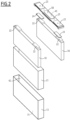
Fig.1] Figure 1 is a perspective view of an energy storage cell, - [
Fig.2] Figure 2 is an exploded view of the energy storage cell ofFigure 1 , - [
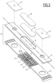
Fig.3] Figure 3 is an exploded view of a venting face of the energy storage cell ofFigure 1 , and - [
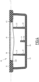
Fig.4] Figure 4 is a cross-sectional partial view along plane IV-IV perpendicular to the venting face of the energy storage cell ofFigure 1 . - The
energy storage cell 10 shown onFigures 1 and2 comprises acan 13, defining a closedinternal volume 15. Thecan 13 is, for example, a metallic parallelepipedal case. - In everything that follows, the terms "internal" and "inner" stand for what is turned towards the
internal volume 15 of thecell 10, and the terms "external" and "outer" stand for what is turned towards the outside of thecell 10. - The
energy storage cell 10 comprises two stacks ofelectrodes 18 enclosed in the closedinternal volume 15. - Before operation of the
energy storage cell 10, thecan 13 is filled with an electrolyte in which the stacks ofelectrodes 18 are immersed. - As can be seen in
Figure 2 , the stacks ofelectrodes 18 are parallelepipedal in shape and are completely enclosed for electrical insulation by aprotective envelope 21. - The
energy storage cell 10 comprisesconnection tabs 22 connecting together the electrodes of the same polarity. Theconnection tabs 22 are electrically connected to respectiveouter connection terminals 23 throughcollectors 24. - The
can 13 comprises a ventingface 25 on which theterminals 23 are exposed. An oblong pass-throughventing window 30 allowing the passage of gases from the closedinternal volume 15 is defined in the ventingface 25. - In the example illustrated in
Figures 1 and2 , the ventingface 25 is the top face of thecan 13. However, the ventingface 25 could also be a lateral face, or a bottom face of thecan 13. - The venting
face 25 comprises anexternal layer 33 superimposed with aninternal layer 36, as shown inFigure 3 . - In this configuration, the pass-through
venting window 30 extends across both theexternal layer 33 and theinternal layer 36. - The pass-through
venting window 30 allows the passage of gases from theinternal volume 15 of thecan 13 towards the outside of theenergy storage cell 10. - The
energy storage cell 10 comprises a ventingmembrane 40 laid across the pass-throughventing window 30, afree space 42, illustrated inFigure 2 , being defined in the closedinternal volume 15 behind the ventingmembrane 40. - The venting
membrane 40 is leak-tight. For example, the ventingmembrane 40 is a sheet of aluminum, having a thickness comprised between 0.2 mm and 0.5 mm - The venting
membrane 40 is welded around the perimeter of the pass-throughventing window 30, and sealingly closes the pass-throughventing window 30. - The venting
membrane 40 is, for example, welded on the inner face of thecan 13. - In the example illustrated in
Figures 3 and4 , the ventingmembrane 40 is fixed to theexternal layer 33 of the ventingface 25. - In particular, the venting
membrane 40 is welded on aninner face 33A of theexternal layer 33 of the ventingface 25. - The
external layer 33 of the ventingface 25 comprises aperipheral shoulder 43 with reduced thickness around the pass-throughventing window 30. Theperipheral shoulder 43 extends along the entire perimeter of the pass-throughventing window 30. - The venting
membrane 40 is welded on the inner side of theperipheral shoulder 43. - Therefore, a fixation plane of the venting
membrane 40 onto the ventingface 25 can be defined. The fixation plane is for example parallel to the ventingface 25. - The venting
membrane 40 is slightly deformable. - By "slightly deformable" it is meant that the venting
membrane 40 is able to be deflected in a concave manner in thefree space 42 towards the inside of thecell 10 in response to a low-pressure condition inside thecell 10 and/or a high-pressure condition outside thecell 10. Similarly, the ventingmembrane 40 is able to be deflected in a convex manner in thefree space 42 towards the outside of thecell 10 in response to a high-pressure condition inside thecell 10 and/or a low-pressure condition outside thecell 10. - The venting
membrane 40 is fixed on the inner side of the peripheral narrowing 43, therefore when an increase in pressure inside thecell 10 occurs, the forces applied to the ventingmembrane 40 are more evenly distributed along the inner side of the peripheral narrowing 43, and the concentration of forces in a local zone of the ventingmembrane 40 is avoided. - In order to support the venting
membrane 40 during the inward deflection, the ventingface 25 comprises a grid extending across the pass-throughventing window 30, in thefree space 42 behind the ventingmembrane 40. - The grid comprises a plurality of
beams 45 andribs membrane 40. Thebeams 45 extend parallel to the fixation plane of the ventingmembrane 40, while theribs membrane 40 and along the ventingmembrane 40. - By "along the venting
membrane 40", it is meant that theribs free space 42, facing the ventingmembrane 40, for example, in any direction along the ventingmembrane 40. - In other words, the
beams 45 and theribs internal volume 15 of thecell 10 to the ventingmembrane 40. - In other words, the
beams 45 and theribs venting window 30 but rather divide the pass-throughventing window 30 into a plurality of pass-through sections for the gas passage. - The
beams 45 and theribs internal layer 36 of the ventingface 25. More precisely, thebeams 45 and theribs internal layer 36 of the ventingface 25. - The
beams 45 and theribs - In a more general way, the
beams 45 and theribs - The grid is for example plastic injection molded with the
internal layer 36 of the ventingface 25. - The
ribs beams 45 by a plurality ofpillars 52 extending across the pass-throughventing window 30. - In the illustrated example, the
pillars 52 are integral with theribs - In the example shown in
Figure 3 , the grid comprisesbeams 45 extending in a transverse direction T and aligned side by side along a longitudinal direction L, across the pass-throughventing window 30. - The
beams 45 extend from one peripheral side of the pass-throughventing window 30 to the opposite peripheral side along the transverse direction T. - The transverse direction T is angularly offset with the longitudinal direction L, for example, the transverse direction T is perpendicular to the longitudinal direction L.
- In the illustrated example, the grid comprises four
ribs free space 42, and dedicated to limiting inward deflections of the ventingmembrane 40 in thefree space 42. - The venting
membrane 40 is, in a normal position, laid at least in part onto theribs - In the example of
Figure 3 , theenergy storage cell 10 comprises onetransverse rib 50, extending in the transverse direction T, and threelongitudinal ribs 51, extending in the longitudinal direction L. Thelongitudinal ribs 51 are aligned side by side along the transverse direction T. - The
longitudinal ribs 51 are divided into two lateral longitudinal ribs extending near the periphery of the pass-throughventing window 30, and one central longitudinal rib extending between the two lateral longitudinal ribs. - The central
longitudinal rib 51 has acentral portion 55, taken between theextremities 53, being further away from the fixation plane of the ventingmembrane 40 than the laterallongitudinal ribs 51, as it can be seen inFigure 4 . - In the normal position of the venting
membrane 40, the ventingmembrane 40 rests directly onto the laterallongitudinal ribs 51, while the ventingmembrane 40 rests only in part onto the centrallongitudinal rib 51. - In other words, the central
longitudinal rib 51 is located at a variable distance from the fixation plane of the ventingmembrane 40 along its length. - In the example shown in
Figure 3 , the centrallongitudinal rib 51 has a variable height, taken perpendicularly to the fixation plane of the ventingmembrane 40 along its length. Theextremities 53 are higher than thecentral portion 55. - The central
longitudinal rib 51 has therefore at least two levels of height, a low level in thecentral portion 55 and a high level around theextremities 53. - Therefore, in the normal position of the venting
membrane 40, the ventingmembrane 40 rests in contact with theextremities 53 of the centrallongitudinal rib 51, while the center of the ventingmembrane 40 is located at a distance from thecentral portion 55 of the centrallongitudinal rib 51. - This feature allows using as little material as possible in the region of gas passage to reduce the fluid dynamic resistance for the gases to flow through the venting
window 30, while still supporting the ventingmembrane 40 effectively thanks to the high-level of height of the centrallongitudinal rib 51 around itsextremities 53. - The low-pressure condition inside the
cell 10 is for example induced during manufacturing of thecell 10, when a vacuum is established inside thecell 10 in order to replace ambient air with the electrolyte. - When the pressure becomes too low, as illustrated in
Figure 4 , thelongitudinal ribs 51 act, over their whole length, as a support for the ventingmembrane 40 and avoid the ventingmembrane 40 to deflect too much. Therefore, a potential breakage of the ventingmembrane 40 at the welded region around the edge is avoided. - Preferably, the
transverse rib 50 has the same height as the laterallongitudinal ribs 51 to ensure sufficient support of the ventingmembrane 40. - Advantageously, the venting
membrane 40 is protected by avent cover 58. Thevent cover 58 is, for example, a thin plastic sheet with a small hole for air scavenge. - The
energy storage cell 10 according to the invention has many advantages. - The
ribs membrane 40 in response to a low internal pressure state. The configuration of theribs membrane 40 can deform enough inwardly without worries of the changes in pressure inside thecell 10. - Therefore, during manufacturing of the
cell 10, when the internal pressure is taken down, for example in an extreme case when the internal pressure goes down to 0 atm in absolute pressure, the venting membrane is supported by theribs membrane 40. - The operation of the
cell 10 can then be carried out safely. -
- 10: energy storage cell
- 13: can
- 15: closed internal volume
- 18: stack of electrodes
- 21: envelope
- 22: tab
- 23: terminal
- 24: collector
- 25: venting face
- 30: venting window
- 33: external layer
- 33A: inner face of the external layer
- 36: internal layer
- 40: venting membrane
- 42: free space
- 43: peripheral shoulder
- 45: beam
- 50, 51: rib
- 50: transversal rib
- 51: longitudinal rib
- 52: pillar
- 53: extremity of the central longitudinal rib
- 55: central portion
- 58: vent cover
- L: longitudinal direction
- T: transversal direction
Claims (12)
- Energy storage cell (10) comprising:- a can (13) defining a closed internal volume (15), and comprising a pass-through venting window (30) allowing the passage of gas from the closed internal volume (15), the pass-through venting window (30) being formed in a venting face (25) of the can (13),- a stack of electrodes (18) enclosed in the closed internal volume (15),- a venting membrane (40) laid across the pass-through venting window (30), a free space (42) being defined in the closed internal volume (15) behind the venting membrane (40),characterized in that, it comprises at least one supporting member (50, 51) in the free space (42), the or each supporting member (50, 51) being dedicated to limiting inwards deflections of the venting membrane (40) in the free space (42).
- Energy storage cell (10) according to claim 1, wherein the or each supporting member comprises a rib (50, 51) extending in the free space (42) along the venting membrane (40).
- Energy storage cell (10) according to claim 1 or 2, wherein the venting face (25) comprises beams (45) extending across the pass-through venting window (30) parallel to a fixation plane of the venting membrane (40), the or each supporting member (50, 51) being linked to the ribs (42) by pillars (52), the pillars (52) extending in a plane angularly offset from the fixation plane of the venting membrane (40).
- Energy storage cell (10) according to any one of the preceding claims, wherein the venting face (25) comprises an external layer (33) superimposed with an internal layer (36), the internal layer (36) comprises the or each supporting members (50, 51), the venting membrane (40) being fixed to the external layer (33).
- Energy storage cell (10) according to any one of the preceding claims, wherein the energy storage cell (10) comprises at least two supporting members (50, 51), which are angularly offset from each other.
- Energy storage cell (10) according to any one of the preceding claims, wherein the or each supporting member (50, 51) is integral with at least one part of the venting face (25).
- Energy storage cell (10) according to any one of the preceding claims, comprising at least two lateral supporting members (51), and at least one central supporting member (51) extending between and along the lateral supporting members (51), the or each central supporting member (51) being for at least a part of its surface, further away from the fixation plane of the venting membrane (40) than the lateral supporting members (51).
- Energy storage cell (10) according to claim 7, wherein the part of the or each central supporting member's surface being further away from the fixation plane of the venting membrane (40) than the lateral supporting members (51), is a central portion (55) of the or each central supporting member (51).
- Energy storage cell (10) according to any one of the preceding claims, wherein the or each supporting member (50 ,51) is configured to allow gas passage from the closed internal volume (15) of the cell (10) to the venting membrane (40).
- Energy storage cell (10) according to any one of the preceding claims, wherein the venting membrane (40) is welded around the perimeter of the pass-through venting window (30), the venting membrane (40) sealingly closing the pass-through venting window (30).
- Energy storage cell (10) according to any one of the preceding claims, wherein the venting membrane (40) is welded on an inner face of the can (13).
- Energy storage cell (10) according to any one of the preceding claims, wherein the venting membrane (40) is, in a normal position, laid at least in part onto the or each supporting member (50, 51).
Priority Applications (1)
| Application Number | Priority Date | Filing Date | Title |
|---|---|---|---|
| EP23306849.3A EP4546537A1 (en) | 2023-10-23 | 2023-10-23 | Energy storage cell comprising supporting member for the venting membrane |
Applications Claiming Priority (1)
| Application Number | Priority Date | Filing Date | Title |
|---|---|---|---|
| EP23306849.3A EP4546537A1 (en) | 2023-10-23 | 2023-10-23 | Energy storage cell comprising supporting member for the venting membrane |
Publications (1)
| Publication Number | Publication Date |
|---|---|
| EP4546537A1 true EP4546537A1 (en) | 2025-04-30 |
Family
ID=88697821
Family Applications (1)
| Application Number | Title | Priority Date | Filing Date |
|---|---|---|---|
| EP23306849.3A Pending EP4546537A1 (en) | 2023-10-23 | 2023-10-23 | Energy storage cell comprising supporting member for the venting membrane |
Country Status (1)
| Country | Link |
|---|---|
| EP (1) | EP4546537A1 (en) |
Citations (4)
| Publication number | Priority date | Publication date | Assignee | Title |
|---|---|---|---|---|
| US20160036025A1 (en) * | 2014-08-04 | 2016-02-04 | Lisa Draexlmaier Gmbh | Degassing valve |
| EP3477756A1 (en) * | 2017-10-30 | 2019-05-01 | Samsung SDI Co., Ltd. | Ventilation device for a battery |
| US20210320375A1 (en) * | 2019-01-04 | 2021-10-14 | Mann+Hummel Gmbh | Degassing Unit and Electronics Housing, in Particular Battery Housing |
| EP4002571A1 (en) * | 2020-11-11 | 2022-05-25 | Siliko d.o.o. | A safety valve for a battery or an accumulator for electric or hybrid vehicles |
-
2023
- 2023-10-23 EP EP23306849.3A patent/EP4546537A1/en active Pending
Patent Citations (4)
| Publication number | Priority date | Publication date | Assignee | Title |
|---|---|---|---|---|
| US20160036025A1 (en) * | 2014-08-04 | 2016-02-04 | Lisa Draexlmaier Gmbh | Degassing valve |
| EP3477756A1 (en) * | 2017-10-30 | 2019-05-01 | Samsung SDI Co., Ltd. | Ventilation device for a battery |
| US20210320375A1 (en) * | 2019-01-04 | 2021-10-14 | Mann+Hummel Gmbh | Degassing Unit and Electronics Housing, in Particular Battery Housing |
| EP4002571A1 (en) * | 2020-11-11 | 2022-05-25 | Siliko d.o.o. | A safety valve for a battery or an accumulator for electric or hybrid vehicles |
Similar Documents
| Publication | Publication Date | Title |
|---|---|---|
| US11949119B2 (en) | Cover assembly of secondary battery and secondary battery | |
| KR101084055B1 (en) | Secondary battery | |
| US10490792B2 (en) | Cap assembly for secondary battery | |
| KR101574082B1 (en) | Rechargeable battery | |
| KR20110041872A (en) | Secondary battery | |
| US20190334145A1 (en) | Battery module | |
| KR20220023100A (en) | Secondary battery | |
| KR20130115594A (en) | Rechargeable battery | |
| KR102846144B1 (en) | Battery cell, and battery pack and vehicle including the same | |
| KR101175008B1 (en) | Cylinderical Rechargeable Battery | |
| KR101520064B1 (en) | Method for producing cap assembly, cap assembly thereby and secondary battery having the same | |
| KR102806743B1 (en) | Cylindrical Secondary Battery Comprising Positive Electrode Tab Fastening Member | |
| KR101465171B1 (en) | Cap assembly and secondary battery having the same | |
| US20240154274A1 (en) | Power storage cell, and method of short-circuiting between lid and external terminal | |
| KR102878356B1 (en) | Cylindrical Battery Cell Having Improved Safety and Manufacturing Method Thereof | |
| KR102293970B1 (en) | Cap Assembly Comprising Current Interruptive Device Made of Bimetal | |
| KR102798777B1 (en) | Secondary battery | |
| KR20240070994A (en) | Battery having a plurality of beading portions | |
| EP4564540A1 (en) | Energy storage cell comprising a precut venting membrane | |
| KR20230063612A (en) | Cylindrical secondary battery and manufacturing method of secondary battery | |
| KR20230049336A (en) | Rechargeable-battery battery | |
| KR102939240B1 (en) | Secondary battery and manufacturing method for the same | |
| US20240396130A1 (en) | Secondary battery | |
| US20240304939A1 (en) | Battery module having improved airtightness and heat resistance of module case | |
| EP4475289A2 (en) | Secondary battery |
Legal Events
| Date | Code | Title | Description |
|---|---|---|---|
| PUAI | Public reference made under article 153(3) epc to a published international application that has entered the european phase |
Free format text: ORIGINAL CODE: 0009012 |
|
| STAA | Information on the status of an ep patent application or granted ep patent |
Free format text: STATUS: THE APPLICATION HAS BEEN PUBLISHED |
|
| AK | Designated contracting states |
Kind code of ref document: A1 Designated state(s): AL AT BE BG CH CY CZ DE DK EE ES FI FR GB GR HR HU IE IS IT LI LT LU LV MC ME MK MT NL NO PL PT RO RS SE SI SK SM TR |
|
| P01 | Opt-out of the competence of the unified patent court (upc) registered |
Free format text: CASE NUMBER: APP_25091/2025 Effective date: 20250527 |
|
| STAA | Information on the status of an ep patent application or granted ep patent |
Free format text: STATUS: REQUEST FOR EXAMINATION WAS MADE |
|
| 17P | Request for examination filed |
Effective date: 20250930 |