EP4546532A1 - Battery pack and vehicle - Google Patents
Battery pack and vehicle Download PDFInfo
- Publication number
- EP4546532A1 EP4546532A1 EP23826567.2A EP23826567A EP4546532A1 EP 4546532 A1 EP4546532 A1 EP 4546532A1 EP 23826567 A EP23826567 A EP 23826567A EP 4546532 A1 EP4546532 A1 EP 4546532A1
- Authority
- EP
- European Patent Office
- Prior art keywords
- battery
- battery cell
- battery pack
- insulating bracket
- connecting sheet
- Prior art date
- Legal status (The legal status is an assumption and is not a legal conclusion. Google has not performed a legal analysis and makes no representation as to the accuracy of the status listed.)
- Pending
Links
Images




Classifications
-
- B—PERFORMING OPERATIONS; TRANSPORTING
- B60—VEHICLES IN GENERAL
- B60L—PROPULSION OF ELECTRICALLY-PROPELLED VEHICLES; SUPPLYING ELECTRIC POWER FOR AUXILIARY EQUIPMENT OF ELECTRICALLY-PROPELLED VEHICLES; ELECTRODYNAMIC BRAKE SYSTEMS FOR VEHICLES IN GENERAL; MAGNETIC SUSPENSION OR LEVITATION FOR VEHICLES; MONITORING OPERATING VARIABLES OF ELECTRICALLY-PROPELLED VEHICLES; ELECTRIC SAFETY DEVICES FOR ELECTRICALLY-PROPELLED VEHICLES
- B60L50/00—Electric propulsion with power supplied within the vehicle
- B60L50/50—Electric propulsion with power supplied within the vehicle using propulsion power supplied by batteries or fuel cells
- B60L50/60—Electric propulsion with power supplied within the vehicle using propulsion power supplied by batteries or fuel cells using power supplied by batteries
- B60L50/64—Constructional details of batteries specially adapted for electric vehicles
-
- H—ELECTRICITY
- H01—ELECTRIC ELEMENTS
- H01M—PROCESSES OR MEANS, e.g. BATTERIES, FOR THE DIRECT CONVERSION OF CHEMICAL ENERGY INTO ELECTRICAL ENERGY
- H01M10/00—Secondary cells; Manufacture thereof
- H01M10/60—Heating or cooling; Temperature control
- H01M10/62—Heating or cooling; Temperature control specially adapted for specific applications
- H01M10/625—Vehicles
-
- H—ELECTRICITY
- H01—ELECTRIC ELEMENTS
- H01M—PROCESSES OR MEANS, e.g. BATTERIES, FOR THE DIRECT CONVERSION OF CHEMICAL ENERGY INTO ELECTRICAL ENERGY
- H01M10/00—Secondary cells; Manufacture thereof
- H01M10/60—Heating or cooling; Temperature control
- H01M10/65—Means for temperature control structurally associated with the cells
- H01M10/655—Solid structures for heat exchange or heat conduction
- H01M10/6554—Rods or plates
-
- H—ELECTRICITY
- H01—ELECTRIC ELEMENTS
- H01M—PROCESSES OR MEANS, e.g. BATTERIES, FOR THE DIRECT CONVERSION OF CHEMICAL ENERGY INTO ELECTRICAL ENERGY
- H01M10/00—Secondary cells; Manufacture thereof
- H01M10/60—Heating or cooling; Temperature control
- H01M10/65—Means for temperature control structurally associated with the cells
- H01M10/655—Solid structures for heat exchange or heat conduction
- H01M10/6556—Solid parts with flow channel passages or pipes for heat exchange
-
- H—ELECTRICITY
- H01—ELECTRIC ELEMENTS
- H01M—PROCESSES OR MEANS, e.g. BATTERIES, FOR THE DIRECT CONVERSION OF CHEMICAL ENERGY INTO ELECTRICAL ENERGY
- H01M50/00—Constructional details or processes of manufacture of the non-active parts of electrochemical cells other than fuel cells, e.g. hybrid cells
- H01M50/20—Mountings; Secondary casings or frames; Racks, modules or packs; Suspension devices; Shock absorbers; Transport or carrying devices; Holders
- H01M50/204—Racks, modules or packs for multiple batteries or multiple cells
-
- H—ELECTRICITY
- H01—ELECTRIC ELEMENTS
- H01M—PROCESSES OR MEANS, e.g. BATTERIES, FOR THE DIRECT CONVERSION OF CHEMICAL ENERGY INTO ELECTRICAL ENERGY
- H01M50/00—Constructional details or processes of manufacture of the non-active parts of electrochemical cells other than fuel cells, e.g. hybrid cells
- H01M50/20—Mountings; Secondary casings or frames; Racks, modules or packs; Suspension devices; Shock absorbers; Transport or carrying devices; Holders
- H01M50/204—Racks, modules or packs for multiple batteries or multiple cells
- H01M50/207—Racks, modules or packs for multiple batteries or multiple cells characterised by their shape
- H01M50/209—Racks, modules or packs for multiple batteries or multiple cells characterised by their shape adapted for prismatic or rectangular cells
-
- H—ELECTRICITY
- H01—ELECTRIC ELEMENTS
- H01M—PROCESSES OR MEANS, e.g. BATTERIES, FOR THE DIRECT CONVERSION OF CHEMICAL ENERGY INTO ELECTRICAL ENERGY
- H01M50/00—Constructional details or processes of manufacture of the non-active parts of electrochemical cells other than fuel cells, e.g. hybrid cells
- H01M50/20—Mountings; Secondary casings or frames; Racks, modules or packs; Suspension devices; Shock absorbers; Transport or carrying devices; Holders
- H01M50/244—Secondary casings; Racks; Suspension devices; Carrying devices; Holders characterised by their mounting method
-
- H—ELECTRICITY
- H01—ELECTRIC ELEMENTS
- H01M—PROCESSES OR MEANS, e.g. BATTERIES, FOR THE DIRECT CONVERSION OF CHEMICAL ENERGY INTO ELECTRICAL ENERGY
- H01M50/00—Constructional details or processes of manufacture of the non-active parts of electrochemical cells other than fuel cells, e.g. hybrid cells
- H01M50/20—Mountings; Secondary casings or frames; Racks, modules or packs; Suspension devices; Shock absorbers; Transport or carrying devices; Holders
- H01M50/249—Mountings; Secondary casings or frames; Racks, modules or packs; Suspension devices; Shock absorbers; Transport or carrying devices; Holders specially adapted for aircraft or vehicles, e.g. cars or trains
-
- H—ELECTRICITY
- H01—ELECTRIC ELEMENTS
- H01M—PROCESSES OR MEANS, e.g. BATTERIES, FOR THE DIRECT CONVERSION OF CHEMICAL ENERGY INTO ELECTRICAL ENERGY
- H01M50/00—Constructional details or processes of manufacture of the non-active parts of electrochemical cells other than fuel cells, e.g. hybrid cells
- H01M50/20—Mountings; Secondary casings or frames; Racks, modules or packs; Suspension devices; Shock absorbers; Transport or carrying devices; Holders
- H01M50/258—Modular batteries; Casings provided with means for assembling
-
- H—ELECTRICITY
- H01—ELECTRIC ELEMENTS
- H01M—PROCESSES OR MEANS, e.g. BATTERIES, FOR THE DIRECT CONVERSION OF CHEMICAL ENERGY INTO ELECTRICAL ENERGY
- H01M50/00—Constructional details or processes of manufacture of the non-active parts of electrochemical cells other than fuel cells, e.g. hybrid cells
- H01M50/20—Mountings; Secondary casings or frames; Racks, modules or packs; Suspension devices; Shock absorbers; Transport or carrying devices; Holders
- H01M50/258—Modular batteries; Casings provided with means for assembling
- H01M50/26—Assemblies sealed to each other in a non-detachable manner
-
- H—ELECTRICITY
- H01—ELECTRIC ELEMENTS
- H01M—PROCESSES OR MEANS, e.g. BATTERIES, FOR THE DIRECT CONVERSION OF CHEMICAL ENERGY INTO ELECTRICAL ENERGY
- H01M50/00—Constructional details or processes of manufacture of the non-active parts of electrochemical cells other than fuel cells, e.g. hybrid cells
- H01M50/20—Mountings; Secondary casings or frames; Racks, modules or packs; Suspension devices; Shock absorbers; Transport or carrying devices; Holders
- H01M50/271—Lids or covers for the racks or secondary casings
-
- H—ELECTRICITY
- H01—ELECTRIC ELEMENTS
- H01M—PROCESSES OR MEANS, e.g. BATTERIES, FOR THE DIRECT CONVERSION OF CHEMICAL ENERGY INTO ELECTRICAL ENERGY
- H01M50/00—Constructional details or processes of manufacture of the non-active parts of electrochemical cells other than fuel cells, e.g. hybrid cells
- H01M50/20—Mountings; Secondary casings or frames; Racks, modules or packs; Suspension devices; Shock absorbers; Transport or carrying devices; Holders
- H01M50/284—Mountings; Secondary casings or frames; Racks, modules or packs; Suspension devices; Shock absorbers; Transport or carrying devices; Holders with incorporated circuit boards, e.g. printed circuit boards [PCB]
-
- H—ELECTRICITY
- H01—ELECTRIC ELEMENTS
- H01M—PROCESSES OR MEANS, e.g. BATTERIES, FOR THE DIRECT CONVERSION OF CHEMICAL ENERGY INTO ELECTRICAL ENERGY
- H01M50/00—Constructional details or processes of manufacture of the non-active parts of electrochemical cells other than fuel cells, e.g. hybrid cells
- H01M50/30—Arrangements for facilitating escape of gases
-
- H—ELECTRICITY
- H01—ELECTRIC ELEMENTS
- H01M—PROCESSES OR MEANS, e.g. BATTERIES, FOR THE DIRECT CONVERSION OF CHEMICAL ENERGY INTO ELECTRICAL ENERGY
- H01M50/00—Constructional details or processes of manufacture of the non-active parts of electrochemical cells other than fuel cells, e.g. hybrid cells
- H01M50/30—Arrangements for facilitating escape of gases
- H01M50/342—Non-re-sealable arrangements
- H01M50/3425—Non-re-sealable arrangements in the form of rupturable membranes or weakened parts, e.g. pierced with the aid of a sharp member
-
- H—ELECTRICITY
- H01—ELECTRIC ELEMENTS
- H01M—PROCESSES OR MEANS, e.g. BATTERIES, FOR THE DIRECT CONVERSION OF CHEMICAL ENERGY INTO ELECTRICAL ENERGY
- H01M50/00—Constructional details or processes of manufacture of the non-active parts of electrochemical cells other than fuel cells, e.g. hybrid cells
- H01M50/30—Arrangements for facilitating escape of gases
- H01M50/35—Gas exhaust passages comprising elongated, tortuous or labyrinth-shaped exhaust passages
- H01M50/358—External gas exhaust passages located on the battery cover or case
-
- H—ELECTRICITY
- H01—ELECTRIC ELEMENTS
- H01M—PROCESSES OR MEANS, e.g. BATTERIES, FOR THE DIRECT CONVERSION OF CHEMICAL ENERGY INTO ELECTRICAL ENERGY
- H01M50/00—Constructional details or processes of manufacture of the non-active parts of electrochemical cells other than fuel cells, e.g. hybrid cells
- H01M50/30—Arrangements for facilitating escape of gases
- H01M50/35—Gas exhaust passages comprising elongated, tortuous or labyrinth-shaped exhaust passages
- H01M50/367—Internal gas exhaust passages forming part of the battery cover or case; Double cover vent systems
-
- H—ELECTRICITY
- H01—ELECTRIC ELEMENTS
- H01M—PROCESSES OR MEANS, e.g. BATTERIES, FOR THE DIRECT CONVERSION OF CHEMICAL ENERGY INTO ELECTRICAL ENERGY
- H01M2220/00—Batteries for particular applications
- H01M2220/20—Batteries in motive systems, e.g. vehicle, ship, plane
-
- Y—GENERAL TAGGING OF NEW TECHNOLOGICAL DEVELOPMENTS; GENERAL TAGGING OF CROSS-SECTIONAL TECHNOLOGIES SPANNING OVER SEVERAL SECTIONS OF THE IPC; TECHNICAL SUBJECTS COVERED BY FORMER USPC CROSS-REFERENCE ART COLLECTIONS [XRACs] AND DIGESTS
- Y02—TECHNOLOGIES OR APPLICATIONS FOR MITIGATION OR ADAPTATION AGAINST CLIMATE CHANGE
- Y02E—REDUCTION OF GREENHOUSE GAS [GHG] EMISSIONS, RELATED TO ENERGY GENERATION, TRANSMISSION OR DISTRIBUTION
- Y02E60/00—Enabling technologies; Technologies with a potential or indirect contribution to GHG emissions mitigation
- Y02E60/10—Energy storage using batteries
Definitions
- the present disclosure relates to the field of battery technologies, and specifically, to a battery pack and a vehicle.
- an explosion-proof valve may be disposed on a housing of the battery cell, and when the fault in the battery cell causes excessive pressure, the explosion-proof valve opens to relief pressure.
- a battery pack is generally disposed at a bottom of a vehicle.
- multiple battery cells are connected in series or in parallel.
- high-temperature and high-pressure gas inside the battery cell is emitted through the explosion-proof valve and impacts other battery cells.
- high-temperature and high-pressure gas in the battery pack is emitted upward, and the gas emitted upward through the explosion-proof valve of the battery pack impacts a passenger compartment, causing injury to a passenger or a driver.
- the present disclosure aims to provide a battery pack and a vehicle, to resolve at least one of the technical problems existing in the related art.
- a battery pack which includes: a sealing cover; a tray, connected to the sealing cover to define an accommodating cavity; multiple battery cells, disposed in the accommodating cavity, a first explosion-proof valve being disposed on a side that is of the battery cell and that faces away from the sealing cover; and an insulating layer, disposed on the side that is of the battery cell and that faces away from the sealing cover, a gas emission piece being disposed on the insulating layer, and the gas emission piece communicating the outside and the first explosion-proof valve.
- the battery pack further includes at least one connecting sheet.
- the connecting sheet is disposed on the insulating layer, and the battery cells are electrically connected to each other through the connecting sheet.
- the insulating layer is an insulating bracket
- the tray includes a bottom plate
- the bottom plate is configured as the insulating bracket.
- the gas emission piece includes a first sub-channel and multiple through holes, the multiple through holes are provided on the insulating bracket, and the first sub-channel is provided in the insulating bracket and configured to be in communication with the outside.
- the multiple through holes are provided in a one-to-one correspondence with first explosion-proof valves of the multiple battery cells, and the multiple through holes are all in communication with the first sub-channel.
- the insulating layer is an insulating bracket
- the tray includes a bottom plate
- the bottom plate has a hollow region
- the insulating bracket is disposed in the hollow region.
- the bottom plate is provided with a first exhaust channel, and the gas emission piece is in communication with the outside through the first exhaust channel.
- the gas emission piece includes a first sub-channel and multiple through holes.
- the multiple through holes are provided on the insulating bracket, the first sub-channel is provided in the insulating bracket, and the multiple through holes are provided in a one-to-one correspondence with first explosion-proof valves of the multiple battery cells.
- the multiple through holes are all in communication with the first sub-channel, and the first sub-channel is in communication with the first exhaust channel.
- the gas emission piece further includes a groove, the groove is provided on the insulating bracket, and the groove is open to a side of the sealing cover.
- the through holes are provided on a bottom wall of the groove, and the battery cell abuts against a sidewall of the groove to form a second sub-channel through enclosure.
- the first sub-channel is provided on a side that is of the insulating bracket and that faces away from the sealing cover, and the first sub-channel and the second sub-channel are oppositely provided and are in communication through the through holes.
- the multiple battery cells are sequentially laid out along a first direction to form a battery cell sequence
- multiple battery cell sequences are disposed and are sequentially laid out along a second direction
- multiple gas emission pieces are disposed and are in a one-to-one correspondence with the multiple battery cell sequences
- the first direction is perpendicular to the second direction.
- a second explosion-proof valve is disposed at an end of the first exhaust channel away from the gas emission piece.
- the insulating bracket is bonded to the tray.
- a diameter of the through hole is greater than a diameter of the first explosion-proof valve.
- the insulating layer is an insulating bracket
- the tray includes a bottom plate
- the insulating bracket is disposed on a side that is of the bottom plate and that faces the sealing cover.
- the gas emission piece includes multiple exhaust holes, and the multiple exhaust holes are provided on the insulating bracket.
- a second exhaust channel is provided in the bottom plate. The multiple exhaust holes are provided in a one-to-one correspondence with first explosion-proof valves of the multiple battery cells, and the multiple exhaust holes are in communication with the outside through the second exhaust channel.
- the battery pack includes at least one connecting sheet, the connecting sheet is disposed on the insulating layer, and the battery cells are electrically connected to each other through the connecting sheet.
- the battery cell has a positive terminal and a negative terminal, the positive terminal and the negative terminal are located on a side that is of the corresponding battery cell and that faces away from the sealing cover, and at least one connecting sheet is electrically connected to a positive terminal of one of the corresponding two battery cells and a negative terminal of the other.
- an accommodating space is provided on a side that is of the insulating bracket and that faces the sealing cover, and a positive terminal of the battery cell and/or a negative terminal of the battery cell are located in the accommodating space.
- a depth of the accommodating space is greater than or equal to a length of the positive terminal or the negative terminal of the corresponding battery cell.
- a surface that is of the battery cell and that is provided with the positive terminal and the negative terminal abuts against the side that is of the insulating bracket and that faces the sealing cover, and the insulating bracket supports the battery cell.
- the multiple battery cells are sequentially laid out along the first direction to form the battery cell sequence, and the accommodating space is distributed on at least one side of the gas emission piece along the second direction.
- the positive terminal of the battery cell and/or the negative terminal of the battery cell are located in the corresponding accommodating space, and the first direction is perpendicular to the second direction.
- the battery pack includes at least one connecting sheet, the connecting sheet is disposed on the insulating layer, the battery cells are electrically connected to each other through the connecting sheet, and the connecting sheet and the insulating bracket are integrally formed; and/or the battery pack further includes at least one sampling member, the sampling member is connected to the corresponding battery cell, and the sampling member and the insulating bracket are integrally formed.
- the sampling member is a sampling harness, FPC, or PCB board.
- the battery pack includes at least one connecting sheet, the connecting sheet is disposed on the insulating layer, and the battery cells are electrically connected to each other through the connecting sheet.
- the battery pack further includes a battery information collector and a circuit board that is separately connected to the battery information collector and the connecting sheet, and the battery information collector, the connecting sheet, and the circuit board each are fastened to the insulating bracket.
- the connecting sheet and the circuit board are integrated on the insulating bracket, and the connecting sheet and the circuit board each are formed integrally with the insulating bracket.
- the connecting sheet is fastened to a side that is of the insulating bracket and that faces the battery cell
- the circuit board is embedded in the insulating bracket
- the battery information collector is fastened to a side that is of the insulating bracket and that faces away from the battery cell.
- the battery pack further includes a heat dissipation plate, provided with a flow channel for flowing a cooling medium.
- the multiple battery cells are laid out along the second direction to form a battery cell group.
- Multiple battery cell groups are disposed, and the multiple battery cell groups are laid out along the first direction.
- the first direction is perpendicular to the second direction, the heat dissipation plate is disposed between any two adjacent battery cell groups, and the heat dissipation plate is thermally connected to the two corresponding battery cell groups.
- the second direction is a width direction of the battery cell
- the first direction is a thickness direction of the battery cell
- a width of the battery cell is greater than a thickness of the battery cell
- an outer surface of the battery cell includes two first surfaces opposed along the first direction, two second surfaces opposed along the second direction, and two third surfaces opposed along a third direction, and the first direction, the second direction, and the third direction are perpendicular to each other.
- the first surface has a largest area, and the heat dissipation plate is thermally connected to a first surface of each battery cell in the two corresponding battery cell groups.
- the battery pack further includes an expansion beam and a cooling plate disposed in the accommodating cavity.
- the expansion beam is disposed adjacent to the multiple battery cells, and the expansion beam is fastened to the tray.
- the cooling plate is pressed against a side that is of the battery cell and that faces the sealing cover, and the cooling plate is fixedly connected to the expansion beam.
- a vehicle including a vehicle body and the battery pack described above.
- the tray is fixedly connected to the vehicle body.
- the vehicle body is integrally formed with the tray or the sealing cover.
- the first explosion-proof valve is disposed on the side that is of the battery cell and that is close to the tray, so that the first explosion-proof valve can emit gas toward the insulating layer below, and the gas can be emitted through the gas emission piece on the insulating layer.
- a downward emission direction of the gas can avoid an upward flow of the gas and can avoid impact on a cab, to reduce injury to a passenger inside the vehicle.
- 10-battery pack 100-battery cell; 1001-battery cell sequence; 1002-battery cell group; 101-first explosion-proof valve; 102-terminal; 1021-positive terminal; 1022-negative terminal; 110-first surface; 120-second surface; 130-third surface; 200-gas emission piece; 21-insulating layer; 210-insulating bracket; 211-third exhaust channel; 2111-second sub-channel; 2112-first sub-channel; 2113-groove; 2114-bottom wall; 2115-sidewall; 212-partition plate; 213-through hole; 214-plate piece; 215-accommodating space; 220-battery information collector; 230-connecting sheet; 231-sample piece; 240-circuit board; 300-tray; 3001-bottom plate; 301-second explosion-proof valve; 302-hollow region; 310-first exhaust channel; 400-sealing cover; 500-expansion beam; 600-cooling plate; 610-heat dissipation plate
- connection may include a mechanical connection, an electrical connection, and the like, and may be determined according to actual functions of components.
- a connection between a connecting sheet and a circuit board is an electrical connection, and a form of the electrical connection may be a wired connection or a wireless connection.
- the present disclosure provides a battery pack, including a sealing cover 400, a tray 300, multiple battery cells 100, and an insulating layer 21.
- the sealing cover 400 is connected to the tray 300 to define an accommodating cavity, and the multiple battery cells 100 are disposed in the accommodating cavity.
- the tray 300 is fixedly connected to a vehicle body.
- the tray 300 may fasten the battery pack to the vehicle body as a whole by bolts.
- the vehicle body is integrally formed with the tray or the sealing cover 400.
- the vehicle body may be a vehicle frame or a chassis.
- Each battery cell 100 has a first explosion-proof valve 101 facing away from the sealing cover 400, or a part of the battery cells 100 each have a first explosion-proof valve 101 facing away from the sealing cover 400. That is, the first explosion-proof valve 101 is disposed on a side that is of each battery cell 100 or a part of the battery cells 100 and that faces away from the sealing cover 400.
- the insulating layer 21 is disposed on the side that is of the battery cell 100 and that faces away from the sealing cover 400, a gas emission piece 200 is disposed on the insulating layer 21, and the gas emission piece 200 communicates the outside and the first explosion-proof valve 101.
- the insulating layer 21 may be an insulating bracket 210 (the insulating bracket 210 and a connecting sheet 230 described below may be integrally formed or assembled as an integral component) or an insulating coating (the insulating coating may be, for example, coated on the tray 300).
- the sealing cover 400 and the tray 300 may be bolted.
- the sealing cover 400 and the tray 300 may be connected by a buckle, and a sealing adhesive is coated on the connection. This is not limited in the present disclosure.
- a type of the first explosion-proof valve 101 is not limited in the present disclosure.
- the first explosion-proof valve 101 may be a rupture disk.
- the gas emission piece 200 may be formed integrally with the insulating bracket 210 by a structural design of the insulating bracket 210.
- the gas emission piece 200 may alternatively be a separate component, and the gas emission piece 200 is fastened to the insulating bracket 210 by bonding or the like. This is not limited in the present disclosure.
- the first explosion-proof valve 101 is disposed on the side that is of the battery cell 100 and that is close to the tray 300, so that the first explosion-proof valve 101 can emit gas toward the insulating layer 21 below, and the gas can be emitted through the gas emission piece 200 on the insulating layer 21.
- a downward emission direction of the gas can avoid an upward flow of the gas and can avoid impact on a cab, to reduce injury to a passenger inside a vehicle.
- the battery pack 10 may further include at least one connecting sheet 230.
- the connecting sheet 230 may be disposed on the insulating layer 21, and the battery cells 100 may be electrically connected to each other through the connecting sheet 230.
- each battery cell 100 may have a positive terminal 1021 and a negative terminal 1022.
- the positive terminal 1021 and the negative terminal 1022 are disposed on a side that is of the corresponding battery cell 100 and that faces away from the sealing cover 400, that is, are disposed on a same side as the first explosion-proof valve 101, so that the battery cell as a whole is "inverted" in the battery pack.
- the positive and negative terminals of the battery cell are disposed downward, to facilitate connection to the connecting sheet 230.
- the at least one connecting sheet 230 is electrically connected to a positive terminal 1021 of one of two corresponding battery cells 100 and a negative terminal 1022 of the other, so that the multiple battery cells 100 are connected to form a battery module.
- the connecting sheet 230 and the terminals 102 may be welded.
- the battery cell 100 may include only a positive terminal 1021, and a housing of the battery cell 100 is negatively charged.
- the connecting sheet 230 is connected to a positive terminal 1021 of one of two battery cells 100 and a housing of the other.
- the battery cell 100 includes only a negative terminal 1022, and a housing of the battery cell 100 is positively charged.
- the connecting sheet 230 is connected to a negative terminal 1022 of one of two battery cells 100 and a housing of the other.
- a side that is of the insulating bracket 210 and that faces the sealing cover 400 may be provided with an accommodating space 215, and the positive terminal 1021 of the battery cell 100 and/or the negative terminal 1022 of the battery cell are located in the accommodating space 215.
- the accommodating space 215 may be formed integrally by a structure of the insulating bracket 210 (for example, as shown in FIG. 12 , the insulating bracket 210 includes a part that is configured as a flat U-shaped structure, and the part is the accommodating space 215).
- the accommodating space 215 may be formed by a concave surface of the insulating bracket 210.
- the accommodating space 215 may be in a groove shape or a hole shape. It may be understood that the accommodating space 215 may accommodate both the positive terminal 1021 and the negative terminal 1022 of the battery, or the positive and negative terminal 1022 of the battery are accommodated in respective different accommodating spaces 215.
- a depth of the accommodating space 215 may be greater than or equal to a length of the positive terminal 1021 or the negative terminal 1022 of the corresponding battery cell 100, to further improve space utilization in the height direction of the battery pack.
- a length of the positive terminal 1021 or the negative terminal 1022 is a distance between two outer surfaces of a part of the terminal exposed from a housing of the battery along an axial direction of the terminal, that is, a distance between an outer surface of the terminal facing away from the sealing cover 400 and a housing of the battery cell 100 in the axial direction of the terminal.
- a surface that is of the battery cell 100 and that is provided with the positive terminal 1021 and the negative terminal 1022 may abut against the side that is of the insulating bracket 210 and that faces the sealing cover 400, and the insulating bracket 210 supports the battery cell 100. In this way, a spacing between the battery cell 100 and the insulating bracket 210 can be reduced, and this helps improve space utilization in the height direction of the battery pack.
- the multiple battery cells 100 are sequentially laid out along a first direction to form a battery cell sequence 1001, and the accommodating space 215 is distributed on at least one side of the gas emission piece 200 along a second direction.
- the positive terminal 1021 of the battery cell 100 and/or the negative terminal 1022 of the battery cell 100 are located in the corresponding accommodating space.
- the first direction intersects the second direction. For example, in the embodiment shown in FIG. 4 , the first direction is perpendicular to the second direction.
- the tray 300 and the insulating bracket 210 are not limited in the present disclosure.
- the tray 300 may be configured to include only a bottom plate or the tray 300 is configured to include a bottom plate and side beams disposed around the bottom plate. In this arrangement, a quantity of structural components in the battery pack can be reduced. This facilitates to improve integration of the battery pack, improve energy density of the battery pack, and reduce costs of the battery pack.
- the bottom plate is configured as the insulating bracket 210. That is, the bottom plate and the insulating bracket 210 are a same component. Therefore, a quantity of components in the battery pack can be reduced, and this facilitates to improve integration of the battery pack.
- the gas emission piece 200 may include a first sub-channel 2112 and multiple through holes 213.
- the multiple through holes 213 are provided on the insulating bracket 210.
- the first sub-channel 2112 is provided in the insulating bracket 210 and is in communication with the outside.
- the multiple through holes 213 are provided in a one-to-one correspondence with first explosion-proof valves 101 of the multiple battery cells 100, and the multiple through holes 213 are all in communication with the first sub-channel 2112. In this way, after the first explosion-proof valve 101 of the battery cell 100 is opened, high-temperature gas in the battery cell 100 may enter the first sub-channel 2112 through the through hole 213, and be emitted to the outside through the first sub-channel 2112. This can prevent the high-temperature gas from flowing upward directly to impact a cab, to reduce injury to a passenger inside the vehicle.
- the bottom plate has a hollow region 302, and the insulating bracket 210 is disposed in the hollow region 302.
- the insulating bracket 210 may be bonded to the tray 300. This design facilitates operation. Certainly, the insulating bracket 210 and the bottom plate may be fastened to each other by channel hot melt connection or screw connection.
- the bottom plate is provided with a first exhaust channel 310, and the gas emission piece 200 is in communication with the outside through the first exhaust channel 310.
- the gas emission piece 200 includes a first sub-channel 2112 and multiple through holes 213. The multiple through holes 213 are provided on the insulating bracket 210.
- the first sub-channel 2112 is provided in the insulating bracket 210.
- the multiple through holes 213 are provided in a one-to-one correspondence with first explosion-proof valves 101 of the multiple battery cells 100.
- the multiple through holes 213 are all in communication with the first sub-channel 2112, and the first sub-channel 2112 is in communication with the first exhaust channel 310.
- high-temperature gas in the battery cell 100 may enter the first sub-channel 2112 through the through hole 213, and be emitted to the outside through the first exhaust channel 310. This can prevent the high-temperature gas from flowing upward directly to impact a cab, to reduce injury to a passenger inside a vehicle.
- a diameter of the through hole 213 may be greater than a diameter of the first explosion-proof valve 101.
- This arrangement facilitates rapid emission of high-temperature gas.
- the diameter of the first explosion-proof valve 101 does not refer to a size of a valve body, but refers to a size of an area distributed by gas emitted from the valve.
- another explosion-proof valve may be disposed at a position close to an outer surface of the battery pack.
- the through holes 213 on the insulating bracket 210 extends along a vertical direction (namely, the height direction of the battery pack)
- the gas emitted from the first explosion-proof valve 101 may enter the first sub-channel 2112 through the through holes 213 and enter the first exhaust channel 310
- a second explosion-proof valve 301 is disposed at one end that is of the first exhaust channel 310 and that is away from the gas emission piece 200.
- the high-temperature gas entering the first exhaust channel 310 can be emitted outside the battery pack through the second explosion-proof valve 301, to avoid damage to another good battery cell 100 in the battery pack.
- the vertical direction refers to a direction perpendicular a surface of the tray 300.
- the through hole 213 may be disposed to extend obliquely according to an actual requirement.
- the gas emission piece 200 may further include a groove 2113.
- the groove 2113 may be provided on the insulating bracket 210, and the groove 2113 is open toward a side of the sealing cover 400.
- the through holes 213 are provided on a bottom wall 2114 of the groove, and the battery cell 100 abuts against a sidewall 2115 of the groove 2113 to form a second sub-channel 2111 through enclosure.
- the first sub-channel 2112 is provided on a side that is of the insulating bracket 210 and that faces away from the sealing cover 400.
- the first sub-channel 2112 and the second sub-channel 2111 are oppositely provided and are in communication through the through holes 213.
- high-temperature gas in the second sub-channel 2111 may enter the first sub-channel 2112 through the through holes 213, and be emitted to the outside through the first sub-channel 2112.
- the first explosion-proof valve 101 corresponding to the battery cell 100 emits high-temperature and high-pressure gas in the battery cell 100.
- the gas flows through the second sub-channel 2111 and enters the first sub-channel 2112 away from another battery cell 100 through the through holes 213. This can prevent the high-temperature and high-pressure gas from remaining in the second sub-channel 2111 and damaging another good battery cell 100.
- the multiple battery cells 100 are sequentially laid out along a first direction to form a battery cell sequence 1001.
- Multiple battery cell sequences 1001 are disposed and laid out along a second direction, multiple gas emission pieces 200 are disposed and are in a one-to-one correspondence with the multiple battery cell sequences 1001, and the first direction is perpendicular to the second direction.
- high-temperature gas in a battery cell 100 in each battery cell sequence 1001 may be emitted to the outside through the gas emission piece 200 corresponding to each battery cell sequence 1001, to reduce mutual interaction.
- the insulating layer 21 is an insulating bracket 210
- the tray 300 includes a bottom plate
- the insulating bracket 210 is disposed on a side that is of the bottom plate and that faces the sealing cover 400 (for example, the insulating bracket 210 abuts against the bottom plate by surface contact).
- the gas emission piece 200 may correspond to a position of the first explosion-proof valves 101 of the multiple battery cells 100, and the gas emitted from the first explosion-proof valve 101 flows inside the bottom plate 3001 through the gas emission piece to flow to the outside.
- the gas emission piece 200 may include multiple exhaust holes, and the multiple exhaust holes are provided on the insulating bracket 210.
- a second exhaust channel is provided in the bottom plate 3001.
- the multiple exhaust holes are provided in a one-to-one correspondence with the first explosion-proof valves 101 of the multiple battery cells 100, and the multiple exhaust holes are in communication with the outside through the second exhaust channel.
- the gas ejected from the first explosion-proof valve 101 enters the second exhaust channel and is emitted through the exhaust hole.
- the battery pack 10 may include at least one connecting sheet 230.
- the connecting sheet 230 may be disposed on the insulating layer 21, and the battery cells 100 may be electrically connected to each other through the connecting sheet 230.
- the connecting sheet and the insulating bracket may be an integrally formed member; and/or the battery pack further includes at least one sampling member 231, the sampling member 231 is connected to the corresponding battery cell 100, and the sampling member 231 and the insulating bracket 210 are integrally formed. In this way, a quantity of structural components in the battery pack can be reduced. This facilitates to improve integration of the battery pack, improve energy density of the battery pack, and reduce costs of the battery pack.
- the sampling member 231 may be a sampling harness, FPC (Flexible Printed Circuit, flexible printed circuit), or PCB board (Printed Circuit Board, printed circuit board).
- FPC Flexible Printed Circuit, flexible printed circuit
- PCB board Printed Circuit Board, printed circuit board
- integration of the first sub-channel 2112 and the second sub-channel 2111 is defined as a third exhaust channel 211.
- the third exhaust channel 211 may be separated by an internal partition plate 212 into the second sub-channel 2111 close to the first explosion-proof valve 101 and the first sub-channel 2112 away from the first explosion-proof valve 101, and the partition plate 212 is provided with a through hole 213 at a position directly opposite to the first explosion-proof valve 101.
- the first explosion-proof valve 101 corresponding to the battery cell 100 emits high-temperature and high-pressure gas in the battery cell 100.
- the gas flows through the second sub-channel 2111 and enters the first sub-channel 2112 away from another battery cell 100 through the through holes 213. This can prevent the high-temperature and high-pressure gas from remaining in the second sub-channel 2111 and damaging another good battery cell 100.
- a first exhaust channel 310 that is in communication with the first sub-channel 2112 is provided on the tray 300, and the first exhaust channel 310 may be located on a side of the first sub-channel 2112.
- the first sub-channel 2112 and the first exhaust channel 310 are aligned in height and each extend parallel to the bottom plate of the tray 300.
- the first exhaust channel 310 extends to a side end surface of the tray 300, and a second explosion-proof valve 301 is disposed at the end.
- the first sub-channel 2112 and the first exhaust channel 310 are aligned in height, so that the first sub-channel 2112 and the first exhaust channel 310 are connected to facilitate gas flowing.
- the heights of the first sub-channel 2112 and the first exhaust channel 310 may be set according to an actual requirement with one being higher and the other lower. In this case, another pipe-type component needs to be disposed between the first sub-channel 2112 and the first exhaust channel 310 for communication.
- the insulating bracket 210 may be bonded to the tray 300.
- the insulating bracket 210 and the tray 300 may be integrally formed. This is not limited in the present disclosure.
- gas may be emitted by a structure located on the insulating bracket 210 or by a structure located on the insulating bracket 210 and the tray 300, and a gas emission path may be shortened.
- An air flow that that breaks through the first explosion-proof valve 101 from the battery cell 100 can quickly flow to the outside of the overall structure of the battery pack, to avoid gas accumulation in the battery pack and avoid damage to another battery cell 100.
- the third exhaust channel 211 and the first exhaust channel 310 may each extend linearly along a first direction. Arranging the third exhaust channel 211 and the first exhaust channel 310 to extend along a straight line can reduce a production process difficulty, and is more conducive to use of internal space of the battery pack.
- an extension path of the third exhaust channel 211 and the first exhaust channel 310 may be set to a curve, a fold line, or the like according to actual use inside the battery pack. It should be explained herein that, referring to FIG.
- the multiple battery cells 100 may be distributed in a matrix, and the first direction may refer to a length direction of a rectangle (an arrow direction of the first direction in the figure). In addition, in other embodiments, the first direction may also refer to a width direction or an oblique direction of the rectangle.
- the present disclosure sets no specific limitation on a layout form of the battery cells 100 and the first direction.
- the battery cells 100 may be located in any direction in a plane in which the insulating bracket 210 is located. The foregoing embodiment is merely an example for description.
- multiple third exhaust channels 211 may be disposed, and are spaced away in a second direction perpendicular to the first direction, and a quantity of first exhaust channels 310 is the same as a quantity of third exhaust channels 211.
- Each third exhaust channel 211 corresponds to a first exhaust channel 310 in communication with the third exhaust channel 211, so that gas in the third exhaust channel 211 can flow into the first exhaust channel 310 and can be emitted through a second explosion-proof valve 301 at an end of the first exhaust channel 310.
- shapes, a quantity, and a layout manner of the third exhaust channels 211 are not limited in the present disclosure, provided that the multiple third exhaust channels 211 can be covered on all first explosion-proof valves 101, so that gas emitted from any first explosion-proof valve 101 can enter the third exhaust channel 211.
- each first explosion-proof valve 101 may correspond to one through hole 213, so that gas emitted from the first explosion-proof valve 101 can directly pass through the through hole 213 to enter the first sub-channel 2112.
- two or three adjacent first explosion-proof valves 101 may share one through hole 213.
- a cross section of the through hole 213 may be in a strip shape, so that gas emitted from the foregoing two or three first explosion-proof valves 101 can pass through the through hole 213.
- multiple third exhaust channels 211 are disposed, and the multiple third exhaust channels 211 each extend linearly in the first direction and are spaced away in a second direction perpendicular to the first direction.
- the insulating bracket 210 includes a plate piece 214 connected to a side of the third exhaust channels 211, and the plate piece 214 may connect the multiple third exhaust channels 211 as a whole.
- the plate piece 214 may further provide mounting space for electronic components (such as a battery information collector 220) to be described below.
- the plate piece 214 may be aligned with the partition plate 212.
- the plate piece 214 and the partition plate 212 may be formed integrally, to reduce a process difficulty.
- the plate piece 214 and the partition plate 212 may be disposed in a structure with one higher and the other lower. This is not limited in the present disclosure.
- the plate piece 214 and the third exhaust channel 211 may form the foregoing flat U-shaped groove structure (the accommodating space 215).
- the battery pack may further include a heat dissipation plate 610, provided with a flow channel for flowing a heat dissipation medium.
- the heat dissipation medium may be a liquid or a refrigerant.
- the multiple battery cells 100 may be laid out along a second direction, to form a battery cell group 1002. Multiple battery cell groups 1002 are disposed, and the multiple battery cell groups 1002 are laid out along the first direction. The first direction is perpendicular to the second direction.
- the heat dissipation plate 610 is disposed between any two adjacent battery cell groups 1002, and the heat dissipation plate 610 is thermally connected to the two corresponding battery cell groups 1002.
- the thermal connection may be understood as direct contact or connection through thermal conductive adhesive.
- the second direction is a width direction of the battery cell 100
- the first direction is a thickness direction of the battery cell 100
- a width of the battery cell 100 may be greater than a thickness of the battery cell 100.
- the battery cell 100 and the heat dissipation plate 610 can have a larger contact heat dissipation area, to improve heat dissipation efficiency.
- the battery cell 100 may also be configured to have a thickness greater than a width. In this case, the heat dissipation plate 610 is disposed on a surface corresponding to the thickness. This is not limited in the present disclosure.
- an outer surface of the battery cell 100 may include two first surfaces 110 opposed along the first direction, two second surfaces 120 opposed along the second direction, and two third surfaces 130 opposed along a third direction.
- the first direction, the second direction, and the third direction are perpendicular to each other.
- the first surface 110 has a largest area, and the heat dissipation plate 610 is thermally connected to a first surface 110 of a battery cell 100 in the two corresponding battery cell groups 1002.
- the thermal connection between the heat dissipation plate 610 and the first surface 110 can ensure a maximum heat dissipation area and a best heat dissipation effect.
- a specific shape of the battery cell 100 and a size relationship of the surfaces are not limited in the present disclosure, provided that the heat dissipation plate 610 can be thermally connected to the battery cell 100, to provide required heat dissipation for the battery cell 100.
- a specific layout manner of the heat dissipation plate 610 may be adjusted according to an actual requirement.
- the first direction is a thickness direction of the battery cell
- the second direction is a width direction of the battery cell
- the third direction is a height direction of the battery cell.
- the height direction of the battery cell is the same as a height direction of the battery pack, that is, is consistent with a height direction of the vehicle.
- a width and a height of the battery cell each are greater than a thickness of the battery cell.
- the second direction is consistent with the length direction of the battery pack.
- the width direction of the battery pack may be consistent with a width direction of the vehicle, and the length direction of the battery pack is consistent with a length direction of the vehicle.
- the battery pack 10 may include at least one connecting sheet 230.
- the connecting sheet 230 may be disposed on the insulating layer 21, and the battery cells 100 may be electrically connected to each other through the connecting sheet 230.
- the battery pack may further include a battery information collector 220 and a circuit board 240 separately connected to the battery information collector 220 and the connecting sheet 230.
- the battery information collector 220, the connecting sheet 230, and the circuit board 240 may be separately fastened to the insulating bracket 210.
- the battery information collector 220 can monitor and obtain information such as a temperature and a pressure of the battery cell 100 in real time, and transfer the obtained information to the circuit board 240.
- the circuit board 240 may control another component (for example, a speaker and an indicator) to make an alert, so that the battery cell 100 can be replaced in time when the battery cell 100 is abnormal.
- the multiple battery cells 100 are connected in series or in parallel through the corresponding connecting sheet 230.
- the electrical connecting sheet 230 may be welded to a terminal of the battery cell 100.
- the connecting sheet 230 and the circuit board 240 may be separately integrated into the insulating bracket 210, and the connecting sheet 230 and the circuit board 240 may be integrally formed with the insulating bracket 210.
- the connecting sheet 230 may be fastened to a side that is of the insulating bracket 210 and that faces the battery cell 100, to connect to the terminal of the battery cell 100.
- the circuit board 240 may be embedded in the insulating bracket 210, and the battery information collector 220 may be fastened to a side that is of the insulating bracket 210 and that faces away from the battery cell 100.
- the battery information collector 220 in the present disclosure may be evenly laid out between multiple third exhaust channels 211, for example, mounted on the plate piece 214.
- the layout position and manner of the battery information collector 220 may be adaptively modified according to an actual requirement. This is not limited in the present disclosure.
- the connecting sheet 230 may be integrally hot pressed on the insulating bracket 210.
- the connecting sheet 230 may be further connected to the insulating bracket 210 by a bolt or the like.
- the battery cells 100 may be connected to the connecting sheet 230 only by terminals, so that the battery cells 100 are fastened to the insulating bracket 210.
- the battery cells 100 and the insulating bracket 210 may further be mechanically or chemically connected, for example, through bonding, bolting, and the like. Because the connection methods are well known to a person skilled in the art, details are not described herein.
- the insulating bracket 210 may be of an SMC material.
- the material has advantages of high mechanical strength, high insulation strength, and the like.
- the insulating bracket 210 may be made of another material having the foregoing advantages. This is not limited in the present disclosure.
- the battery pack may further include an expansion beam 500 and a cooling plate 600 disposed in the accommodating cavity.
- the expansion beam 500 is disposed adjacent to the multiple battery cells 100, and the expansion beam 500 is fastened to the tray 300.
- the cooling plate 600 is pressed against a side that is of the battery cell 100 and that faces the sealing cover, and the cooling plate 600 is fixedly connected to the expansion beam 500. In this way, the cooling plate 600 can both limit the battery cells 100 and cool the battery cells 100.
- cooling plate 600 may be a liquid container provided with multiple pipe connectors 800, and completes water circulation through water inflow and outflow of the multiple pipe connectors 800.
- the cooling plate 600 may also perform cooling by gas circulation.
- arrangement of the expansion beam 500 adjacent to the multiple battery cells 100 means that the expansion beam 500 may directly or indirectly abut against the battery cells 100.
- the expansion beam 500 is well known to a person skilled in the art, and is not described herein.
- the battery pack may further include a distribution box 700 disposed in the accommodating cavity.
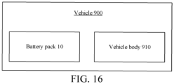
- a vehicle 900 including a vehicle body 910 and the foregoing battery pack 10.
- the tray 300 is fixedly connected to the vehicle body 910, or the vehicle body 910 is integrally formed with the tray 300 or the sealing cover 400.
- the vehicle body 910 may be a vehicle frame or a chassis of the vehicle 900.
- the vehicle 900 has all beneficial effects of the battery pack 10, and details are not described herein again.
Landscapes
- Chemical & Material Sciences (AREA)
- Chemical Kinetics & Catalysis (AREA)
- Electrochemistry (AREA)
- General Chemical & Material Sciences (AREA)
- Engineering & Computer Science (AREA)
- Manufacturing & Machinery (AREA)
- Aviation & Aerospace Engineering (AREA)
- Life Sciences & Earth Sciences (AREA)
- Sustainable Development (AREA)
- Sustainable Energy (AREA)
- Power Engineering (AREA)
- Transportation (AREA)
- Mechanical Engineering (AREA)
- Battery Mounting, Suspending (AREA)
- Gas Exhaust Devices For Batteries (AREA)
- Connection Of Batteries Or Terminals (AREA)
Abstract
Description
- The present disclosure claims priority to and benefits of
Chinese Patent Application No. 202221617994.8, filed on June 23, 2022 Chinese Patent Application No. 202320076673.X, filed on January 9, 2023 - The present disclosure relates to the field of battery technologies, and specifically, to a battery pack and a vehicle.
- When a fault occurs in a battery cell of a power battery, high-temperature and high-pressure gas is generated inside the battery cell. To prevent a possible explosion, an explosion-proof valve may be disposed on a housing of the battery cell, and when the fault in the battery cell causes excessive pressure, the explosion-proof valve opens to relief pressure.
- In a related art, a battery pack is generally disposed at a bottom of a vehicle. When the battery pack is assembled, multiple battery cells are connected in series or in parallel. When a fault occurs in a battery cell, high-temperature and high-pressure gas inside the battery cell is emitted through the explosion-proof valve and impacts other battery cells. When a thermal failure occurs in the entire battery pack, high-temperature and high-pressure gas in the battery pack is emitted upward, and the gas emitted upward through the explosion-proof valve of the battery pack impacts a passenger compartment, causing injury to a passenger or a driver.
- The present disclosure aims to provide a battery pack and a vehicle, to resolve at least one of the technical problems existing in the related art.
- To achieve the above objective, a battery pack is provided, which includes: a sealing cover; a tray, connected to the sealing cover to define an accommodating cavity; multiple battery cells, disposed in the accommodating cavity, a first explosion-proof valve being disposed on a side that is of the battery cell and that faces away from the sealing cover; and an insulating layer, disposed on the side that is of the battery cell and that faces away from the sealing cover, a gas emission piece being disposed on the insulating layer, and the gas emission piece communicating the outside and the first explosion-proof valve.
- Optionally, the battery pack further includes at least one connecting sheet. The connecting sheet is disposed on the insulating layer, and the battery cells are electrically connected to each other through the connecting sheet.
- Optionally, the insulating layer is an insulating bracket, the tray includes a bottom plate, and the bottom plate is configured as the insulating bracket.
- Optionally, the gas emission piece includes a first sub-channel and multiple through holes, the multiple through holes are provided on the insulating bracket, and the first sub-channel is provided in the insulating bracket and configured to be in communication with the outside. The multiple through holes are provided in a one-to-one correspondence with first explosion-proof valves of the multiple battery cells, and the multiple through holes are all in communication with the first sub-channel.
- Optionally, the insulating layer is an insulating bracket, the tray includes a bottom plate, the bottom plate has a hollow region, and the insulating bracket is disposed in the hollow region.
- Optionally, the bottom plate is provided with a first exhaust channel, and the gas emission piece is in communication with the outside through the first exhaust channel.
- Optionally, the gas emission piece includes a first sub-channel and multiple through holes. The multiple through holes are provided on the insulating bracket, the first sub-channel is provided in the insulating bracket, and the multiple through holes are provided in a one-to-one correspondence with first explosion-proof valves of the multiple battery cells. The multiple through holes are all in communication with the first sub-channel, and the first sub-channel is in communication with the first exhaust channel.
- Optionally, the gas emission piece further includes a groove, the groove is provided on the insulating bracket, and the groove is open to a side of the sealing cover. The through holes are provided on a bottom wall of the groove, and the battery cell abuts against a sidewall of the groove to form a second sub-channel through enclosure. The first sub-channel is provided on a side that is of the insulating bracket and that faces away from the sealing cover, and the first sub-channel and the second sub-channel are oppositely provided and are in communication through the through holes.
- Optionally, the multiple battery cells are sequentially laid out along a first direction to form a battery cell sequence, multiple battery cell sequences are disposed and are sequentially laid out along a second direction, multiple gas emission pieces are disposed and are in a one-to-one correspondence with the multiple battery cell sequences, and the first direction is perpendicular to the second direction.
- Optionally, a second explosion-proof valve is disposed at an end of the first exhaust channel away from the gas emission piece.
- Optionally, the insulating bracket is bonded to the tray.
- Optionally, a diameter of the through hole is greater than a diameter of the first explosion-proof valve.
- Optionally, the insulating layer is an insulating bracket, the tray includes a bottom plate, and the insulating bracket is disposed on a side that is of the bottom plate and that faces the sealing cover. The gas emission piece includes multiple exhaust holes, and the multiple exhaust holes are provided on the insulating bracket. A second exhaust channel is provided in the bottom plate. The multiple exhaust holes are provided in a one-to-one correspondence with first explosion-proof valves of the multiple battery cells, and the multiple exhaust holes are in communication with the outside through the second exhaust channel.
- Optionally, the battery pack includes at least one connecting sheet, the connecting sheet is disposed on the insulating layer, and the battery cells are electrically connected to each other through the connecting sheet. The battery cell has a positive terminal and a negative terminal, the positive terminal and the negative terminal are located on a side that is of the corresponding battery cell and that faces away from the sealing cover, and at least one connecting sheet is electrically connected to a positive terminal of one of the corresponding two battery cells and a negative terminal of the other.
- Optionally, an accommodating space is provided on a side that is of the insulating bracket and that faces the sealing cover, and a positive terminal of the battery cell and/or a negative terminal of the battery cell are located in the accommodating space.
- Optionally, a depth of the accommodating space is greater than or equal to a length of the positive terminal or the negative terminal of the corresponding battery cell.
- Optionally, a surface that is of the battery cell and that is provided with the positive terminal and the negative terminal abuts against the side that is of the insulating bracket and that faces the sealing cover, and the insulating bracket supports the battery cell.
- Optionally, the multiple battery cells are sequentially laid out along the first direction to form the battery cell sequence, and the accommodating space is distributed on at least one side of the gas emission piece along the second direction. The positive terminal of the battery cell and/or the negative terminal of the battery cell are located in the corresponding accommodating space, and the first direction is perpendicular to the second direction.
- Optionally, the battery pack includes at least one connecting sheet, the connecting sheet is disposed on the insulating layer, the battery cells are electrically connected to each other through the connecting sheet, and the connecting sheet and the insulating bracket are integrally formed; and/or the battery pack further includes at least one sampling member, the sampling member is connected to the corresponding battery cell, and the sampling member and the insulating bracket are integrally formed.
- Optionally, the sampling member is a sampling harness, FPC, or PCB board.
- Optionally, the battery pack includes at least one connecting sheet, the connecting sheet is disposed on the insulating layer, and the battery cells are electrically connected to each other through the connecting sheet. The battery pack further includes a battery information collector and a circuit board that is separately connected to the battery information collector and the connecting sheet, and the battery information collector, the connecting sheet, and the circuit board each are fastened to the insulating bracket.
- Optionally, the connecting sheet and the circuit board are integrated on the insulating bracket, and the connecting sheet and the circuit board each are formed integrally with the insulating bracket. The connecting sheet is fastened to a side that is of the insulating bracket and that faces the battery cell, the circuit board is embedded in the insulating bracket, and the battery information collector is fastened to a side that is of the insulating bracket and that faces away from the battery cell.
- Optionally, the battery pack further includes a heat dissipation plate, provided with a flow channel for flowing a cooling medium. The multiple battery cells are laid out along the second direction to form a battery cell group. Multiple battery cell groups are disposed, and the multiple battery cell groups are laid out along the first direction. The first direction is perpendicular to the second direction, the heat dissipation plate is disposed between any two adjacent battery cell groups, and the heat dissipation plate is thermally connected to the two corresponding battery cell groups.
- Optionally, the second direction is a width direction of the battery cell, the first direction is a thickness direction of the battery cell, and a width of the battery cell is greater than a thickness of the battery cell.
- Optionally, an outer surface of the battery cell includes two first surfaces opposed along the first direction, two second surfaces opposed along the second direction, and two third surfaces opposed along a third direction, and the first direction, the second direction, and the third direction are perpendicular to each other. In the first surface, the second surface, and the third surface, the first surface has a largest area, and the heat dissipation plate is thermally connected to a first surface of each battery cell in the two corresponding battery cell groups.
- Optionally, the battery pack further includes an expansion beam and a cooling plate disposed in the accommodating cavity. The expansion beam is disposed adjacent to the multiple battery cells, and the expansion beam is fastened to the tray. The cooling plate is pressed against a side that is of the battery cell and that faces the sealing cover, and the cooling plate is fixedly connected to the expansion beam.
- According to a second aspect of the present disclosure, a vehicle is provided, including a vehicle body and the battery pack described above. The tray is fixedly connected to the vehicle body. Alternatively, the vehicle body is integrally formed with the tray or the sealing cover.
- According to the foregoing technical solution, the first explosion-proof valve is disposed on the side that is of the battery cell and that is close to the tray, so that the first explosion-proof valve can emit gas toward the insulating layer below, and the gas can be emitted through the gas emission piece on the insulating layer. A downward emission direction of the gas can avoid an upward flow of the gas and can avoid impact on a cab, to reduce injury to a passenger inside the vehicle.
- Other features and advantages of the present disclosure will be described in detail in the following detailed description part.
- The accompanying drawings are intended to provide further understanding of the present disclosure and constitute a part of this specification. The accompanying drawings and the specific implementations below are used together for explaining the present disclosure rather than constituting a limitation to the present disclosure. In the accompanying drawings:
-
FIG. 1 is a diagram of a battery pack according to an embodiment of the present disclosure; -
FIG. 2 is a diagram of a battery pack according to an embodiment of the present disclosure; -
FIG. 3 is a diagram of a battery pack according to an embodiment of the present disclosure; -
FIG. 4 is a diagram of a battery pack according to an embodiment of the present disclosure; -
FIG. 5 is an exploded diagram of a battery pack according to an embodiment of the present disclosure; -
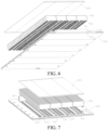
FIG. 6 is an exploded diagram of a battery pack according to an embodiment of the present disclosure; -
FIG. 7 is an exploded diagram of a battery pack according to an embodiment of the present disclosure; -
FIG. 8 is a diagram of a battery pack according to an embodiment of the present disclosure; -
FIG. 9 is a diagram of a battery pack according to an embodiment of the present disclosure; -
FIG. 10 is a diagram of a battery pack according to an embodiment of the present disclosure; -
FIG. 11 is a diagram of an insulating bracket of a battery pack according to an embodiment of the present disclosure; -
FIG. 12 is a diagram of an insulating bracket of a battery pack according to an embodiment of the present disclosure; -
FIG. 13 is a cross-sectional view along A-A inFIG. 1 ; -
FIG. 14 is a partial enlarged view of a part B inFIG. 10 ; -
FIG. 15 is an exploded diagram of a battery pack according to an embodiment of the present disclosure; and -
FIG. 16 is a diagram of a vehicle according to an embodiment of the present disclosure. - 10-battery pack; 100-battery cell; 1001-battery cell sequence; 1002-battery cell group; 101-first explosion-proof valve; 102-terminal; 1021-positive terminal; 1022-negative terminal; 110-first surface; 120-second surface; 130-third surface; 200-gas emission piece; 21-insulating layer; 210-insulating bracket; 211-third exhaust channel; 2111-second sub-channel; 2112-first sub-channel; 2113-groove; 2114-bottom wall; 2115-sidewall; 212-partition plate; 213-through hole; 214-plate piece; 215-accommodating space; 220-battery information collector; 230-connecting sheet; 231-sample piece; 240-circuit board; 300-tray; 3001-bottom plate; 301-second explosion-proof valve; 302-hollow region; 310-first exhaust channel; 400-sealing cover; 500-expansion beam; 600-cooling plate; 610-heat dissipation plate; 700-distribution box; 800-pipe connector; 900-vehicle; 910-vehicle body.
- Specific implementations of the present disclosure are described in detail below with reference to the accompanying drawings. It should be understood that the specific implementations described herein are merely used to describe and explain the present disclosure, but are not intended to limit the present disclosure.
- In the present disclosure, unless otherwise stated, directional terms such as "inner and outer" refer to inside and outside of a contour of a corresponding component. The "connection" mentioned in the following may include a mechanical connection, an electrical connection, and the like, and may be determined according to actual functions of components. For example, a connection between a connecting sheet and a circuit board is an electrical connection, and a form of the electrical connection may be a wired connection or a wireless connection.
- Furthermore, terms such as "first" and "second" are used in the present disclosure to distinguish an element from another element, and are not of sequence or importance. When the following description involves the accompanying drawings, unless otherwise indicated, the same numerals in different accompanying drawings represent the same or similar elements.
- As shown in
FIG. 1 to FIG. 7 , the present disclosure provides a battery pack, including a sealing cover 400, atray 300,multiple battery cells 100, and an insulatinglayer 21. The sealing cover 400 is connected to thetray 300 to define an accommodating cavity, and themultiple battery cells 100 are disposed in the accommodating cavity. When the battery pack is used in a vehicle, thetray 300 is fixedly connected to a vehicle body. For example, thetray 300 may fasten the battery pack to the vehicle body as a whole by bolts. Alternatively, the vehicle body is integrally formed with the tray or the sealing cover 400. The vehicle body may be a vehicle frame or a chassis. Eachbattery cell 100 has a first explosion-proof valve 101 facing away from the sealing cover 400, or a part of thebattery cells 100 each have a first explosion-proof valve 101 facing away from the sealing cover 400. That is, the first explosion-proof valve 101 is disposed on a side that is of eachbattery cell 100 or a part of thebattery cells 100 and that faces away from the sealing cover 400. The insulatinglayer 21 is disposed on the side that is of thebattery cell 100 and that faces away from the sealing cover 400, agas emission piece 200 is disposed on the insulatinglayer 21, and thegas emission piece 200 communicates the outside and the first explosion-proof valve 101. The insulatinglayer 21 may be an insulating bracket 210 (the insulatingbracket 210 and a connectingsheet 230 described below may be integrally formed or assembled as an integral component) or an insulating coating (the insulating coating may be, for example, coated on the tray 300). Herein, in this embodiment of the present disclosure, the sealing cover 400 and thetray 300 may be bolted. In addition, in other embodiments, the sealing cover 400 and thetray 300 may be connected by a buckle, and a sealing adhesive is coated on the connection. This is not limited in the present disclosure. - A type of the first explosion-
proof valve 101 is not limited in the present disclosure. For example, in this embodiment of the present disclosure, the first explosion-proof valve 101 may be a rupture disk. In this embodiment of the present disclosure, thegas emission piece 200 may be formed integrally with the insulatingbracket 210 by a structural design of the insulatingbracket 210. In addition, in other embodiments, thegas emission piece 200 may alternatively be a separate component, and thegas emission piece 200 is fastened to the insulatingbracket 210 by bonding or the like. This is not limited in the present disclosure. - According to the foregoing technical solution, the first explosion-
proof valve 101 is disposed on the side that is of thebattery cell 100 and that is close to thetray 300, so that the first explosion-proof valve 101 can emit gas toward the insulatinglayer 21 below, and the gas can be emitted through thegas emission piece 200 on the insulatinglayer 21. A downward emission direction of the gas can avoid an upward flow of the gas and can avoid impact on a cab, to reduce injury to a passenger inside a vehicle. - To connect the
multiple battery cells 100 in series or in parallel as a whole, in this embodiment of the present disclosure, thebattery pack 10 may further include at least one connectingsheet 230. The connectingsheet 230 may be disposed on the insulatinglayer 21, and thebattery cells 100 may be electrically connected to each other through the connectingsheet 230. - Further, in this embodiment of the present disclosure, each
battery cell 100 may have apositive terminal 1021 and anegative terminal 1022. Thepositive terminal 1021 and thenegative terminal 1022 are disposed on a side that is of thecorresponding battery cell 100 and that faces away from the sealing cover 400, that is, are disposed on a same side as the first explosion-proof valve 101, so that the battery cell as a whole is "inverted" in the battery pack. In this arrangement, the positive and negative terminals of the battery cell are disposed downward, to facilitate connection to the connectingsheet 230. The at least one connectingsheet 230 is electrically connected to apositive terminal 1021 of one of twocorresponding battery cells 100 and anegative terminal 1022 of the other, so that themultiple battery cells 100 are connected to form a battery module. Herein, in this embodiment of the present disclosure, the connectingsheet 230 and theterminals 102 may be welded. Certainly, in another embodiment, thebattery cell 100 may include only apositive terminal 1021, and a housing of thebattery cell 100 is negatively charged. In this case, the connectingsheet 230 is connected to apositive terminal 1021 of one of twobattery cells 100 and a housing of the other. Alternatively, thebattery cell 100 includes only anegative terminal 1022, and a housing of thebattery cell 100 is positively charged. In this case, the connectingsheet 230 is connected to anegative terminal 1022 of one of twobattery cells 100 and a housing of the other. - Refer to
FIG. 12 . In this embodiment of the present disclosure, a side that is of the insulatingbracket 210 and that faces the sealing cover 400 may be provided with anaccommodating space 215, and thepositive terminal 1021 of thebattery cell 100 and/or thenegative terminal 1022 of the battery cell are located in theaccommodating space 215. Herein, in this embodiment of the present disclosure, theaccommodating space 215 may be formed integrally by a structure of the insulating bracket 210 (for example, as shown inFIG. 12 , the insulatingbracket 210 includes a part that is configured as a flat U-shaped structure, and the part is the accommodating space 215). In addition, in other embodiments, theaccommodating space 215 may be formed by a concave surface of the insulatingbracket 210. This is not limited in the present disclosure. In this arrangement, space of the accommodating cavity occupied by thebattery cell 100 in a height direction can be reduced, and space utilization in the height direction of the battery pack is improved. Theaccommodating space 215 may be in a groove shape or a hole shape. It may be understood that theaccommodating space 215 may accommodate both thepositive terminal 1021 and thenegative terminal 1022 of the battery, or the positive andnegative terminal 1022 of the battery are accommodated in respective differentaccommodating spaces 215. - Further, a depth of the
accommodating space 215 may be greater than or equal to a length of the positive terminal 1021 or thenegative terminal 1022 of thecorresponding battery cell 100, to further improve space utilization in the height direction of the battery pack. It should be noted that a length of the positive terminal 1021 or thenegative terminal 1022 is a distance between two outer surfaces of a part of the terminal exposed from a housing of the battery along an axial direction of the terminal, that is, a distance between an outer surface of the terminal facing away from the sealing cover 400 and a housing of thebattery cell 100 in the axial direction of the terminal. - In addition, a surface that is of the
battery cell 100 and that is provided with thepositive terminal 1021 and thenegative terminal 1022 may abut against the side that is of the insulatingbracket 210 and that faces the sealing cover 400, and the insulatingbracket 210 supports thebattery cell 100. In this way, a spacing between thebattery cell 100 and the insulatingbracket 210 can be reduced, and this helps improve space utilization in the height direction of the battery pack. - In some embodiments, referring to
FIG. 4 , themultiple battery cells 100 are sequentially laid out along a first direction to form abattery cell sequence 1001, and theaccommodating space 215 is distributed on at least one side of thegas emission piece 200 along a second direction. Thepositive terminal 1021 of thebattery cell 100 and/or thenegative terminal 1022 of thebattery cell 100 are located in the corresponding accommodating space. The first direction intersects the second direction. For example, in the embodiment shown inFIG. 4 , the first direction is perpendicular to the second direction. - Specific formation methods of the
tray 300 and the insulatingbracket 210 are not limited in the present disclosure. Thetray 300 may be configured to include only a bottom plate or thetray 300 is configured to include a bottom plate and side beams disposed around the bottom plate. In this arrangement, a quantity of structural components in the battery pack can be reduced. This facilitates to improve integration of the battery pack, improve energy density of the battery pack, and reduce costs of the battery pack. - For example, in some embodiments, the bottom plate is configured as the insulating
bracket 210. That is, the bottom plate and the insulatingbracket 210 are a same component. Therefore, a quantity of components in the battery pack can be reduced, and this facilitates to improve integration of the battery pack. - Further, the
gas emission piece 200 may include afirst sub-channel 2112 and multiple throughholes 213. The multiple throughholes 213 are provided on the insulatingbracket 210. Thefirst sub-channel 2112 is provided in the insulatingbracket 210 and is in communication with the outside. The multiple throughholes 213 are provided in a one-to-one correspondence with first explosion-proof valves 101 of themultiple battery cells 100, and the multiple throughholes 213 are all in communication with thefirst sub-channel 2112. In this way, after the first explosion-proof valve 101 of thebattery cell 100 is opened, high-temperature gas in thebattery cell 100 may enter thefirst sub-channel 2112 through the throughhole 213, and be emitted to the outside through thefirst sub-channel 2112. This can prevent the high-temperature gas from flowing upward directly to impact a cab, to reduce injury to a passenger inside the vehicle. - In other embodiments, the bottom plate has a
hollow region 302, and the insulatingbracket 210 is disposed in thehollow region 302. The insulatingbracket 210 may be bonded to thetray 300. This design facilitates operation. Certainly, the insulatingbracket 210 and the bottom plate may be fastened to each other by channel hot melt connection or screw connection. Further, the bottom plate is provided with afirst exhaust channel 310, and thegas emission piece 200 is in communication with the outside through thefirst exhaust channel 310. Specifically, thegas emission piece 200 includes afirst sub-channel 2112 and multiple throughholes 213. The multiple throughholes 213 are provided on the insulatingbracket 210. Thefirst sub-channel 2112 is provided in the insulatingbracket 210. The multiple throughholes 213 are provided in a one-to-one correspondence with first explosion-proof valves 101 of themultiple battery cells 100. The multiple throughholes 213 are all in communication with thefirst sub-channel 2112, and thefirst sub-channel 2112 is in communication with thefirst exhaust channel 310. In this way, after the first explosion-proof valve 101 of thebattery cell 100 is opened, high-temperature gas in thebattery cell 100 may enter thefirst sub-channel 2112 through the throughhole 213, and be emitted to the outside through thefirst exhaust channel 310. This can prevent the high-temperature gas from flowing upward directly to impact a cab, to reduce injury to a passenger inside a vehicle. - Optionally, a diameter of the through
hole 213 may be greater than a diameter of the first explosion-proof valve 101. This arrangement facilitates rapid emission of high-temperature gas. Herein, it should be explained that the diameter of the first explosion-proof valve 101 does not refer to a size of a valve body, but refers to a size of an area distributed by gas emitted from the valve. - In some embodiments, to emit, through the
gas emission piece 200, high-temperature and high-pressure gas emitted from the first explosion-proof valve 101, another explosion-proof valve may be disposed at a position close to an outer surface of the battery pack. Referring toFIG. 9, FIG. 10 , andFIG. 14 , in some embodiments, the throughholes 213 on the insulatingbracket 210 extends along a vertical direction (namely, the height direction of the battery pack), the gas emitted from the first explosion-proof valve 101 may enter thefirst sub-channel 2112 through the throughholes 213 and enter thefirst exhaust channel 310, and a second explosion-proof valve 301 is disposed at one end that is of thefirst exhaust channel 310 and that is away from thegas emission piece 200. In this way, the high-temperature gas entering thefirst exhaust channel 310 can be emitted outside the battery pack through the second explosion-proof valve 301, to avoid damage to anothergood battery cell 100 in the battery pack. Herein, it should be explained that the vertical direction refers to a direction perpendicular a surface of thetray 300. In addition, in other embodiments, the throughhole 213 may be disposed to extend obliquely according to an actual requirement. - In some embodiments, the
gas emission piece 200 may further include agroove 2113. Thegroove 2113 may be provided on the insulatingbracket 210, and thegroove 2113 is open toward a side of the sealing cover 400. The throughholes 213 are provided on abottom wall 2114 of the groove, and thebattery cell 100 abuts against asidewall 2115 of thegroove 2113 to form asecond sub-channel 2111 through enclosure. Thefirst sub-channel 2112 is provided on a side that is of the insulatingbracket 210 and that faces away from the sealing cover 400. Thefirst sub-channel 2112 and thesecond sub-channel 2111 are oppositely provided and are in communication through the throughholes 213. In this way, high-temperature gas in thesecond sub-channel 2111 may enter thefirst sub-channel 2112 through the throughholes 213, and be emitted to the outside through thefirst sub-channel 2112. In this design, when thebattery cell 100 is faulty, the first explosion-proof valve 101 corresponding to thebattery cell 100 emits high-temperature and high-pressure gas in thebattery cell 100. The gas flows through thesecond sub-channel 2111 and enters thefirst sub-channel 2112 away from anotherbattery cell 100 through the throughholes 213. This can prevent the high-temperature and high-pressure gas from remaining in thesecond sub-channel 2111 and damaging anothergood battery cell 100. - In some embodiments, the
multiple battery cells 100 are sequentially laid out along a first direction to form abattery cell sequence 1001. Multiplebattery cell sequences 1001 are disposed and laid out along a second direction, multiplegas emission pieces 200 are disposed and are in a one-to-one correspondence with the multiplebattery cell sequences 1001, and the first direction is perpendicular to the second direction. In this way, high-temperature gas in abattery cell 100 in eachbattery cell sequence 1001 may be emitted to the outside through thegas emission piece 200 corresponding to eachbattery cell sequence 1001, to reduce mutual interaction. - In other embodiments, the insulating
layer 21 is aninsulating bracket 210, thetray 300 includes a bottom plate, the insulatingbracket 210 is disposed on a side that is of the bottom plate and that faces the sealing cover 400 (for example, the insulatingbracket 210 abuts against the bottom plate by surface contact). Thegas emission piece 200 may correspond to a position of the first explosion-proof valves 101 of themultiple battery cells 100, and the gas emitted from the first explosion-proof valve 101 flows inside thebottom plate 3001 through the gas emission piece to flow to the outside. Thegas emission piece 200 may include multiple exhaust holes, and the multiple exhaust holes are provided on the insulatingbracket 210. A second exhaust channel is provided in thebottom plate 3001. The multiple exhaust holes are provided in a one-to-one correspondence with the first explosion-proof valves 101 of themultiple battery cells 100, and the multiple exhaust holes are in communication with the outside through the second exhaust channel. The gas ejected from the first explosion-proof valve 101 enters the second exhaust channel and is emitted through the exhaust hole. - According to some embodiments, the
battery pack 10 may include at least one connectingsheet 230. The connectingsheet 230 may be disposed on the insulatinglayer 21, and thebattery cells 100 may be electrically connected to each other through the connectingsheet 230. The connecting sheet and the insulating bracket may be an integrally formed member; and/or the battery pack further includes at least onesampling member 231, the samplingmember 231 is connected to thecorresponding battery cell 100, and thesampling member 231 and the insulatingbracket 210 are integrally formed. In this way, a quantity of structural components in the battery pack can be reduced. This facilitates to improve integration of the battery pack, improve energy density of the battery pack, and reduce costs of the battery pack. - The sampling
member 231 may be a sampling harness, FPC (Flexible Printed Circuit, flexible printed circuit), or PCB board (Printed Circuit Board, printed circuit board). - In the foregoing embodiment with the
first sub-channel 2112 and thesecond sub-channel 2111, integration of thefirst sub-channel 2112 and thesecond sub-channel 2111 is defined as a third exhaust channel 211. In this case, referring toFIG. 11 to FIG. 13 , the third exhaust channel 211 may be separated by aninternal partition plate 212 into thesecond sub-channel 2111 close to the first explosion-proof valve 101 and thefirst sub-channel 2112 away from the first explosion-proof valve 101, and thepartition plate 212 is provided with a throughhole 213 at a position directly opposite to the first explosion-proof valve 101. In this design, when thebattery cell 100 is faulty, the first explosion-proof valve 101 corresponding to thebattery cell 100 emits high-temperature and high-pressure gas in thebattery cell 100. The gas flows through thesecond sub-channel 2111 and enters thefirst sub-channel 2112 away from anotherbattery cell 100 through the throughholes 213. This can prevent the high-temperature and high-pressure gas from remaining in thesecond sub-channel 2111 and damaging anothergood battery cell 100. - In this embodiment, a
first exhaust channel 310 that is in communication with thefirst sub-channel 2112 is provided on thetray 300, and thefirst exhaust channel 310 may be located on a side of thefirst sub-channel 2112. Thefirst sub-channel 2112 and thefirst exhaust channel 310 are aligned in height and each extend parallel to the bottom plate of thetray 300. Thefirst exhaust channel 310 extends to a side end surface of thetray 300, and a second explosion-proof valve 301 is disposed at the end. - Herein, the
first sub-channel 2112 and thefirst exhaust channel 310 are aligned in height, so that thefirst sub-channel 2112 and thefirst exhaust channel 310 are connected to facilitate gas flowing. In addition, in other embodiments, the heights of thefirst sub-channel 2112 and thefirst exhaust channel 310 may be set according to an actual requirement with one being higher and the other lower. In this case, another pipe-type component needs to be disposed between thefirst sub-channel 2112 and thefirst exhaust channel 310 for communication. - For the foregoing case in which the insulating
bracket 210 needs to be mounted on thetray 300, in some embodiments, the insulatingbracket 210 may be bonded to thetray 300. In addition, in other embodiments, the insulatingbracket 210 and thetray 300 may be integrally formed. This is not limited in the present disclosure. - In the foregoing embodiment, gas may be emitted by a structure located on the insulating
bracket 210 or by a structure located on the insulatingbracket 210 and thetray 300, and a gas emission path may be shortened. An air flow that that breaks through the first explosion-proof valve 101 from thebattery cell 100 can quickly flow to the outside of the overall structure of the battery pack, to avoid gas accumulation in the battery pack and avoid damage to anotherbattery cell 100. - Refer to
FIG. 8 to FIG. 10 . In this embodiment of the present disclosure, the third exhaust channel 211 and thefirst exhaust channel 310 may each extend linearly along a first direction. Arranging the third exhaust channel 211 and thefirst exhaust channel 310 to extend along a straight line can reduce a production process difficulty, and is more conducive to use of internal space of the battery pack. In addition, in other embodiments, an extension path of the third exhaust channel 211 and thefirst exhaust channel 310 may be set to a curve, a fold line, or the like according to actual use inside the battery pack. It should be explained herein that, referring toFIG. 5 , in this embodiment of the present disclosure, themultiple battery cells 100 may be distributed in a matrix, and the first direction may refer to a length direction of a rectangle (an arrow direction of the first direction in the figure). In addition, in other embodiments, the first direction may also refer to a width direction or an oblique direction of the rectangle. The present disclosure sets no specific limitation on a layout form of thebattery cells 100 and the first direction. Thebattery cells 100 may be located in any direction in a plane in which the insulatingbracket 210 is located. The foregoing embodiment is merely an example for description. - Further, to enable all gas emitted from the first explosion-
proof valve 101 to enter the third exhaust channel 211, referring toFIG. 1 , in this embodiment of the present disclosure, multiple third exhaust channels 211 may be disposed, and are spaced away in a second direction perpendicular to the first direction, and a quantity offirst exhaust channels 310 is the same as a quantity of third exhaust channels 211. Each third exhaust channel 211 corresponds to afirst exhaust channel 310 in communication with the third exhaust channel 211, so that gas in the third exhaust channel 211 can flow into thefirst exhaust channel 310 and can be emitted through a second explosion-proof valve 301 at an end of thefirst exhaust channel 310. As described above, shapes, a quantity, and a layout manner of the third exhaust channels 211 are not limited in the present disclosure, provided that the multiple third exhaust channels 211 can be covered on all first explosion-proof valves 101, so that gas emitted from any first explosion-proof valve 101 can enter the third exhaust channel 211. - In this embodiment of the present disclosure, each first explosion-
proof valve 101 may correspond to one throughhole 213, so that gas emitted from the first explosion-proof valve 101 can directly pass through the throughhole 213 to enter thefirst sub-channel 2112. In addition, in other embodiments, two or three adjacent first explosion-proof valves 101 may share one throughhole 213. In this case, a cross section of the throughhole 213 may be in a strip shape, so that gas emitted from the foregoing two or three first explosion-proof valves 101 can pass through the throughhole 213. - In this embodiment of the present disclosure, referring to
FIG. 1 , multiple third exhaust channels 211 are disposed, and the multiple third exhaust channels 211 each extend linearly in the first direction and are spaced away in a second direction perpendicular to the first direction. The insulatingbracket 210 includes aplate piece 214 connected to a side of the third exhaust channels 211, and theplate piece 214 may connect the multiple third exhaust channels 211 as a whole. In addition, theplate piece 214 may further provide mounting space for electronic components (such as a battery information collector 220) to be described below. - In this embodiment of the present disclosure, the
plate piece 214 may be aligned with thepartition plate 212. In this design, during production, theplate piece 214 and thepartition plate 212 may be formed integrally, to reduce a process difficulty. In addition, in other embodiments, considering mounting space of another component, theplate piece 214 and thepartition plate 212 may be disposed in a structure with one higher and the other lower. This is not limited in the present disclosure. - In addition to the foregoing advantages, the
plate piece 214 and the third exhaust channel 211 may form the foregoing flat U-shaped groove structure (the accommodating space 215). - In this embodiment of the present disclosure, the battery pack may further include a
heat dissipation plate 610, provided with a flow channel for flowing a heat dissipation medium. The heat dissipation medium may be a liquid or a refrigerant. Themultiple battery cells 100 may be laid out along a second direction, to form abattery cell group 1002. Multiplebattery cell groups 1002 are disposed, and the multiplebattery cell groups 1002 are laid out along the first direction. The first direction is perpendicular to the second direction. Theheat dissipation plate 610 is disposed between any two adjacentbattery cell groups 1002, and theheat dissipation plate 610 is thermally connected to the two correspondingbattery cell groups 1002. By arranging theheat dissipation plate 610 between the two adjacentbattery cell groups 1002, heat generated by thebattery cells 100 during operation can be quickly dissipated, to avoid a potential safety hazard caused by an excessive temperature inside the battery pack. The thermal connection may be understood as direct contact or connection through thermal conductive adhesive. - Further, to increase a heat dissipation area, in this embodiment of the present disclosure, the second direction is a width direction of the
battery cell 100, the first direction is a thickness direction of thebattery cell 100, and a width of thebattery cell 100 may be greater than a thickness of thebattery cell 100. In this design, thebattery cell 100 and theheat dissipation plate 610 can have a larger contact heat dissipation area, to improve heat dissipation efficiency. In addition, in other embodiments, thebattery cell 100 may also be configured to have a thickness greater than a width. In this case, theheat dissipation plate 610 is disposed on a surface corresponding to the thickness. This is not limited in the present disclosure. - Refer to
FIG. 5 . In this embodiment of the present disclosure, an outer surface of thebattery cell 100 may include twofirst surfaces 110 opposed along the first direction, twosecond surfaces 120 opposed along the second direction, and twothird surfaces 130 opposed along a third direction. The first direction, the second direction, and the third direction are perpendicular to each other. In thefirst surface 110, thesecond surface 120, and thethird surface 130, thefirst surface 110 has a largest area, and theheat dissipation plate 610 is thermally connected to afirst surface 110 of abattery cell 100 in the two correspondingbattery cell groups 1002. Because thefirst surface 110 of thebattery cell 100 has the largest area, the thermal connection between theheat dissipation plate 610 and thefirst surface 110 can ensure a maximum heat dissipation area and a best heat dissipation effect. A specific shape of thebattery cell 100 and a size relationship of the surfaces are not limited in the present disclosure, provided that theheat dissipation plate 610 can be thermally connected to thebattery cell 100, to provide required heat dissipation for thebattery cell 100. A specific layout manner of theheat dissipation plate 610 may be adjusted according to an actual requirement. In some embodiments, the first direction is a thickness direction of the battery cell, the second direction is a width direction of the battery cell, and the third direction is a height direction of the battery cell. The height direction of the battery cell is the same as a height direction of the battery pack, that is, is consistent with a height direction of the vehicle. A width and a height of the battery cell each are greater than a thickness of the battery cell. When the first direction is consistent with the width direction of the battery pack, the second direction is consistent with the length direction of the battery pack. When the first direction is consistent with the length direction of the battery pack, the second direction is consistent with the width direction of the battery pack. In addition, the width direction of the battery pack may be consistent with a width direction of the vehicle, and the length direction of the battery pack is consistent with a length direction of the vehicle. - Refer to
FIG. 11 and FIG. 12 . In this embodiment of the present disclosure, thebattery pack 10 may include at least one connectingsheet 230. The connectingsheet 230 may be disposed on the insulatinglayer 21, and thebattery cells 100 may be electrically connected to each other through the connectingsheet 230. The battery pack may further include abattery information collector 220 and acircuit board 240 separately connected to thebattery information collector 220 and the connectingsheet 230. Thebattery information collector 220, the connectingsheet 230, and thecircuit board 240 may be separately fastened to the insulatingbracket 210. Herein, thebattery information collector 220 can monitor and obtain information such as a temperature and a pressure of thebattery cell 100 in real time, and transfer the obtained information to thecircuit board 240. When receiving abnormal temperature or pressure information, thecircuit board 240 may control another component (for example, a speaker and an indicator) to make an alert, so that thebattery cell 100 can be replaced in time when thebattery cell 100 is abnormal. Themultiple battery cells 100 are connected in series or in parallel through the corresponding connectingsheet 230. In this embodiment of the present disclosure, the electrical connectingsheet 230 may be welded to a terminal of thebattery cell 100. - Further, in this embodiment of the present disclosure, the connecting
sheet 230 and thecircuit board 240 may be separately integrated into the insulatingbracket 210, and the connectingsheet 230 and thecircuit board 240 may be integrally formed with the insulatingbracket 210. The connectingsheet 230 may be fastened to a side that is of the insulatingbracket 210 and that faces thebattery cell 100, to connect to the terminal of thebattery cell 100. Thecircuit board 240 may be embedded in the insulatingbracket 210, and thebattery information collector 220 may be fastened to a side that is of the insulatingbracket 210 and that faces away from thebattery cell 100. - The
battery information collector 220 in the present disclosure may be evenly laid out between multiple third exhaust channels 211, for example, mounted on theplate piece 214. In addition, in other embodiments, the layout position and manner of thebattery information collector 220 may be adaptively modified according to an actual requirement. This is not limited in the present disclosure. - In this embodiment of the present disclosure, the connecting
sheet 230 may be integrally hot pressed on the insulatingbracket 210. In addition, in other embodiments, the connectingsheet 230 may be further connected to the insulatingbracket 210 by a bolt or the like. - Refer to
FIG. 1 . In this embodiment of the present disclosure, thebattery cells 100 may be connected to the connectingsheet 230 only by terminals, so that thebattery cells 100 are fastened to the insulatingbracket 210. In addition, in other embodiments, to enhance connection strength between thebattery cells 100 and the insulatingbracket 210 and prevent separation between thebattery cells 100 and the insulatingbracket 210 due to an external force, thebattery cells 100 and the insulatingbracket 210 may further be mechanically or chemically connected, for example, through bonding, bolting, and the like. Because the connection methods are well known to a person skilled in the art, details are not described herein. - To ensure structural strength of the insulating
bracket 210 and improve stability of a component mounted on the insulatingbracket 210, in this embodiment of the present disclosure, the insulatingbracket 210 may be of an SMC material. The material has advantages of high mechanical strength, high insulation strength, and the like. In addition, in other embodiments, the insulatingbracket 210 may be made of another material having the foregoing advantages. This is not limited in the present disclosure. - To enable real-time cooling and heat dissipation of components such as the
battery cells 100 during use of the battery pack, referring toFIG. 1 , in this embodiment of the present disclosure, the battery pack may further include anexpansion beam 500 and acooling plate 600 disposed in the accommodating cavity. Theexpansion beam 500 is disposed adjacent to themultiple battery cells 100, and theexpansion beam 500 is fastened to thetray 300. Thecooling plate 600 is pressed against a side that is of thebattery cell 100 and that faces the sealing cover, and thecooling plate 600 is fixedly connected to theexpansion beam 500. In this way, thecooling plate 600 can both limit thebattery cells 100 and cool thebattery cells 100. - A specific form of the
cooling plate 600 is not limited in the present disclosure. For example, in this embodiment of the present disclosure, thecooling plate 600 may be a liquid container provided withmultiple pipe connectors 800, and completes water circulation through water inflow and outflow of themultiple pipe connectors 800. In addition, in other embodiments, thecooling plate 600 may also perform cooling by gas circulation. - In this embodiment of the present disclosure, arrangement of the
expansion beam 500 adjacent to themultiple battery cells 100 means that theexpansion beam 500 may directly or indirectly abut against thebattery cells 100. Theexpansion beam 500 is well known to a person skilled in the art, and is not described herein. - Refer to
FIG. 1 . In this embodiment of the present disclosure, the battery pack may further include adistribution box 700 disposed in the accommodating cavity. - Refer to
FIG. 16 . According to a second aspect of the present disclosure, avehicle 900 is provided, including avehicle body 910 and the foregoingbattery pack 10. Thetray 300 is fixedly connected to thevehicle body 910, or thevehicle body 910 is integrally formed with thetray 300 or the sealing cover 400. Thevehicle body 910 may be a vehicle frame or a chassis of thevehicle 900. Thevehicle 900 has all beneficial effects of thebattery pack 10, and details are not described herein again. - The implementations of the present disclosure are described in detail above with reference to the accompanying drawings. However, the present disclosure is not limited to the specific details in the foregoing implementations, a plurality of simple deformations may be made to the technical solution of the present disclosure within a range of the technical concept of the present disclosure, and these simple deformations fall within the protection scope of the present disclosure.
- It should be additionally noted that, the specific technical features described in the foregoing specific implementations may be combined in any proper manner in a case without conflict. To avoid unnecessary repetition, various possible combinations are not further described in the present disclosure.
- In addition, different implementations of the present disclosure may also be arbitrarily combined without departing from the idea of the present disclosure, and these combinations shall still be regarded as content disclosed in the present disclosure.
Claims (27)
- A battery pack (10), comprising:a sealing cover (400);a tray (300), connecting to the sealing cover (400) to define an accommodating cavity;a plurality of battery cells (100), arranging in the accommodating cavity, a first explosion-proof valve (101) being disposed on a side that is of the battery cell (100) and that facing away from the sealing cover (400); andan insulating layer (21), arranging on the side that is of the battery cell (100) and that facing away from the sealing cover (400), a gas emission piece (200) being disposed on the insulating layer (21), and the gas emission piece (200) communicating the outside and the first explosion-proof valve (101).
- The battery pack (10) according to claim 1, further comprising: at least one connecting sheet (230), the connecting sheet (230) being disposed on the insulating layer (21), and the battery cells (100) being electrically connected to each other through the connecting sheet (230).
- The battery pack (10) according to claim 1 or 2, wherein the insulating layer (21) is an insulating bracket (210), the tray (300) comprises a bottom plate (3001), and the bottom plate (3001) is configured as the insulating bracket (210).
- The battery pack (10) according to claim 3, wherein the gas emission piece (200) comprises a first sub-channel (2112) and a plurality of through holes (213), the plurality of through holes (213) are provided on the insulating bracket (210), the first sub-channel (2112) is provided in the insulating bracket (210) and is in communication with the outside, the plurality of through holes (213) are provided in a one-to-one correspondence with first explosion-proof valves (101) of the plurality of battery cells (100), and the plurality of through holes (213) are all in communication with the first sub-channel (2112).
- The battery pack (10) according to claim 1 or 2, wherein the insulating layer (21) is an insulating bracket (210), the tray (300) comprises a bottom plate (3001), the bottom plate (3001) has a hollow region (302), and the insulating bracket (210) is disposed in the hollow region (302).
- The battery pack (10) according to claim 5, wherein a first exhaust channel (310) is disposed in the bottom plate (3001), and the gas emission piece (200) is in communication with the outside through the first exhaust channel (310).
- The battery pack (10) according to claim 6, wherein the gas emission piece (200) comprises a first sub-channel (2112) and a plurality of through holes (213), the plurality of through holes (213) are provided on the insulating bracket (210), the first sub-channel (2112) is provided in the insulating bracket (210), the plurality of through holes (213) are provided in a one-to-one correspondence with first explosion-proof valves (101) of the plurality of battery cells (100), the plurality of through holes (213) are all in communication with the first sub-channel (2112), and the first sub-channel (2112) is in communication with the first exhaust channel (310).
- The battery pack (10) according to claim 4 or 7, wherein the gas emission piece (200) further comprises a groove (2113), the groove (2113) is provided on the insulating bracket (210), the groove (2113) is open to a side of the sealing cover (400), the through holes (213) are provided on a bottom wall (2114) of the groove (2113), the battery cell (100) abuts against a sidewall (2115) of the groove (2113) to form a second sub-channel (2111) through enclosure, the first sub-channel (2112) is provided on a side that is of the insulating bracket (210) and that faces away from the sealing cover (400), and the first sub-channel (2112) and the second sub-channel (2111) are oppositely provided and are in communication through the through holes (213).
- The battery pack (10) according to claim 8, wherein the plurality of battery cells (100) are sequentially laid out along a first direction to form a battery cell sequence (1001), a plurality of battery cell sequences (1001) are disposed and are sequentially laid out along a second direction, a plurality of gas emission pieces (200) are disposed and are in a one-to-one correspondence with the plurality of battery cell sequences (1001), and the first direction is perpendicular to the second direction.
- The battery pack (10) according to claim 6 or 7, wherein a second explosion-proof valve (301) is disposed at an end of the first exhaust channel (310) away from the gas emission piece.
- The battery pack (10) according to any one of claims 5 to 7 and 10, wherein the insulating bracket (210) is bonded to the tray (300).
- The battery pack (10) according to claim 4 or 7, wherein a diameter of the through hole (213) is greater than a diameter of the first explosion-proof valve (101).
- The battery pack (10) according to claim 1 or 2, wherein the insulating layer (21) is an insulating bracket (210), the tray (300) comprises a bottom plate (3001), the insulating bracket (210) is disposed on a side that is of the bottom plate (3001) and that faces the sealing cover (400), the gas emission piece (200) comprises a plurality of exhaust holes, the plurality of exhaust holes are provided on the insulating bracket (210), a second exhaust channel is provided in the bottom plate (3001), the plurality of exhaust holes are provided in a one-to-one correspondence with first explosion-proof valves (101) of the plurality of battery cells (100), and the plurality of exhaust holes are in communication with the outside through the second exhaust channel.
- The battery pack (10) according to any one of claims 3 to 13, comprising at least one connecting sheet (230), the connecting sheet (230) being disposed on the insulating layer (21), and the battery cells (100) being electrically connected to each other through the connecting sheet (230), wherein
the battery cell (100) has a positive terminal (1021) and a negative terminal (1022), the positive terminal (1021) and the negative terminal (1022) are located on a side that is of the corresponding battery cell (100) and that faces away from the sealing cover (400), and at least one connecting sheet (230) is electrically connected to a positive terminal (1021) of one of the corresponding two battery cells (100) and a negative terminal (1022) of the other. - The battery pack (10) according to claim 14, wherein a side that is of the insulating bracket (210) and that faces the sealing cover (400) is provided with an accommodating space (215), and the positive terminal (1021) of the battery cell (100) and/or the negative terminal (1022) of the battery cell (100) are located in the accommodating space (215).
- The battery pack (10) according to claim 15, wherein a depth of the accommodating space (215) is greater than or equal to a length of the positive terminal (1021) or the negative terminal (1022) of the corresponding battery cell (100).
- The battery pack (10) according to claim 15 or 16, wherein a surface that is of the battery cell (100) and that is provided with the positive terminal (1021) and the negative terminal (1022) abuts against the side that is of the insulating bracket (210) and that faces the sealing cover (400), and the insulating bracket (210) supports the battery cell (100).
- The battery pack (10) according to any one of claims 15 to 17, wherein the plurality of battery cells (100) are sequentially laid out along the first direction to form the battery cell sequence (1001), the accommodating space (215) is distributed on at least one side of the gas emission piece (200) along the second direction, the positive terminal (1021) of the battery cell (100) and/or the negative terminal (1022) of the battery cell (100) are located in the corresponding accommodating space (215), and the first direction is perpendicular to the second direction.
- The battery pack (10) according to any one of claims 3 to 18, comprising at least one connecting sheet (230), the connecting sheet (230) being disposed on the insulating layer (21), and the battery cells (100) being electrically connected to each other through the connecting sheet (230), whereinthe connecting sheet (230) and the insulating bracket (210) are integrally formed; and/orthe battery pack further comprises at least one sampling member (231), the sampling member (231) is connected to the corresponding battery cell (100), and the sampling member (231) and the insulating bracket (210) are integrally formed.
- The battery pack (10) according to claim 19, wherein the sampling member (231) is a sampling harness, FPC, or PCB board.
- The battery pack (10) according to any one of claims 3 to 20, comprising at least one connecting sheet (230), the connecting sheet (230) being disposed on the insulating layer (21), and the battery cells (100) being electrically connected to each other through the connecting sheet (230), wherein
the battery pack (10) further comprises a battery information collector (220) and a circuit board (240) that is separately connected to the battery information collector (220) and the connecting sheet (230), and the battery information collector (220), the connecting sheet (230), and the circuit board (240) each are fastened to the insulating bracket (210). - The battery pack (10) according to claim 21, wherein the connecting sheet (230) and the circuit board (240) each are integrated on the insulating bracket (210), and the connecting sheet (230) and the circuit board (240) each are formed integrally with the insulating bracket (210), wherein the connecting sheet (230) is fastened to a side that is of the insulating bracket (210) and that faces the battery cell (100), the circuit board (240) is embedded in the insulating bracket (210), and the battery information collector (220) is fastened to a side that is of the insulating bracket (210) and that faces away from the battery cell (100).
- The battery pack (10) according to any one of claims 1 to 22, further comprising a heat dissipation plate (610), provided with a flow channel for flowing a cooling medium, the plurality of battery cells (100) being laid out along the second direction to form a battery cell group (1002), a plurality of battery cell groups (1002) being disposed, the plurality of battery cell groups (1002) being laid out along the first direction, the first direction being perpendicular to the second direction, the heat dissipation plate (610) being disposed between any two adjacent battery cell groups (1002), and the heat dissipation plate (610) being thermally connected to the two corresponding battery cell groups (1002).
- The battery pack (10) according to claim 23, wherein the second direction is a width direction of the battery cell (100), the first direction is a thickness direction of the battery cell (100), and a width of the battery cell (100) is greater than a thickness of the battery cell (100).
- The battery pack (10) according to claim 24, wherein an outer surface of the battery cell (100) comprises two first surfaces (110) opposed along the first direction, two second surfaces (120) opposed along the second direction, and two third surfaces (130) opposed along a third direction, and the first direction, the second direction, and the third direction are perpendicular to each other; and
in the first surface (110), the second surface (120), and the third surface (130), the first surface (110) has a largest area, and the heat dissipation plate (610) is thermally connected to a first surface (110) of each battery cell (100) in the two corresponding battery cell groups (1002). - The battery pack (10) according to any one of claims 1 to 25, further comprising an expansion beam (500) and a cooling plate (600) disposed in the accommodating cavity, the expansion beam (500) being disposed adjacent to the plurality of battery cells (100), the expansion beam (500) being fastened to the tray (300), the cooling plate (600) being pressed against a side that is of the battery cell (100) and that faces the sealing cover (400), and the cooling plate (600) being fixedly connected to the expansion beam (500).
- A vehicle (900), comprising: a vehicle body (910) and the battery pack (10) according to any one of claims 1 to 26, the tray (300) being fixedly connected to the vehicle body (910); or the vehicle body (910) being integrally formed with the tray (300) or the sealing cover (400).
Applications Claiming Priority (3)
| Application Number | Priority Date | Filing Date | Title |
|---|---|---|---|
| CN202221617994 | 2022-06-23 | ||
| CN202320076673.XU CN219329349U (en) | 2022-06-23 | 2023-01-09 | Battery pack and vehicle |
| PCT/CN2023/101957 WO2023246922A1 (en) | 2022-06-23 | 2023-06-21 | Battery pack and vehicle |
Publications (2)
| Publication Number | Publication Date |
|---|---|
| EP4546532A1 true EP4546532A1 (en) | 2025-04-30 |
| EP4546532A4 EP4546532A4 (en) | 2025-12-10 |
Family
ID=86218195
Family Applications (1)
| Application Number | Title | Priority Date | Filing Date |
|---|---|---|---|
| EP23826567.2A Pending EP4546532A4 (en) | 2022-06-23 | 2023-06-21 | BATTERY PACK AND VEHICLE |
Country Status (6)
| Country | Link |
|---|---|
| US (1) | US20250105421A1 (en) |
| EP (1) | EP4546532A4 (en) |
| JP (1) | JP2025518815A (en) |
| KR (1) | KR20250021368A (en) |
| CN (2) | CN218996901U (en) |
| WO (1) | WO2023246922A1 (en) |
Cited By (1)
| Publication number | Priority date | Publication date | Assignee | Title |
|---|---|---|---|---|
| EP4738567A1 (en) * | 2024-10-30 | 2026-05-06 | Toyota Jidosha Kabushiki Kaisha | Power storage device |
Families Citing this family (6)
| Publication number | Priority date | Publication date | Assignee | Title |
|---|---|---|---|---|
| CN222338405U (en) * | 2024-02-06 | 2025-01-10 | 宁德时代新能源科技股份有限公司 | Battery and electricity utilization device |
| CN118017141A (en) * | 2024-03-21 | 2024-05-10 | 欣旺达动力科技股份有限公司 | Battery packs and electrical equipment |
| CN222838995U (en) * | 2024-05-23 | 2025-05-06 | 惠州亿纬锂能股份有限公司 | A CCS component and battery pack |
| CN118970278B (en) * | 2024-07-30 | 2025-10-24 | 肇庆小鹏汽车有限公司 | Battery pack and vehicle |
| CN223052239U (en) * | 2024-08-27 | 2025-07-01 | 惠州亿纬锂能股份有限公司 | Battery cell module and battery pack |
| CN119340524B (en) * | 2024-09-19 | 2025-12-12 | 华为数字能源技术有限公司 | Battery packs and energy storage cabinets |
Family Cites Families (20)
| Publication number | Priority date | Publication date | Assignee | Title |
|---|---|---|---|---|
| US8748021B2 (en) * | 2010-10-19 | 2014-06-10 | Samsung Sdi Co., Ltd. | Battery module |
| CN103208598B (en) * | 2012-01-16 | 2016-06-29 | 微宏动力系统(湖州)有限公司 | Set of cells and method for detecting leakage thereof |
| CN103208656B (en) * | 2012-01-16 | 2016-03-30 | 微宏动力系统(湖州)有限公司 | Battery pack system and method for detecting leakage thereof |
| JP7147253B2 (en) * | 2018-05-09 | 2022-10-05 | 株式会社Gsユアサ | power storage device |
| JP7466108B2 (en) * | 2018-07-31 | 2024-04-12 | パナソニックIpマネジメント株式会社 | Battery module and battery pack |
| CN111106277B (en) * | 2018-12-29 | 2021-05-07 | 宁德时代新能源科技股份有限公司 | Battery pack |
| JP7133491B2 (en) * | 2019-01-31 | 2022-09-08 | マレリ株式会社 | Assembled battery and coating method |
| CN111755636B (en) * | 2019-03-28 | 2021-09-17 | 宁德时代新能源科技股份有限公司 | Battery pack |
| JP7259673B2 (en) * | 2019-09-20 | 2023-04-18 | トヨタ自動車株式会社 | battery pack |
| KR102656955B1 (en) * | 2020-07-10 | 2024-04-11 | 컨템포러리 엠퍼렉스 테크놀로지 씨오., 리미티드 | Batteries and related devices, manufacturing methods and manufacturing equipment |
| CN118017138A (en) * | 2020-07-10 | 2024-05-10 | 宁德时代新能源科技股份有限公司 | Battery and related device, preparation method and preparation equipment thereof |
| EP4064435A4 (en) * | 2020-09-30 | 2024-04-24 | Contemporary Amperex Technology Co., Limited | Battery, device, and preparation method and preparation device for battery |
| CN216389613U (en) * | 2021-11-08 | 2022-04-26 | 宁德时代新能源科技股份有限公司 | Battery pack and vehicle |
| CN215771430U (en) * | 2021-12-06 | 2022-02-08 | 比亚迪股份有限公司 | Battery pack and vehicle having the same |
| CN216793807U (en) * | 2021-12-15 | 2022-06-21 | 远景动力技术(江苏)有限公司 | Battery pack |
| CN216597870U (en) * | 2021-12-20 | 2022-05-24 | 蜂巢能源科技股份有限公司 | Battery pack and powerplant having the same |
| CN114597574B (en) * | 2022-03-25 | 2024-10-11 | 广州小鹏汽车科技有限公司 | Battery cell module and power battery assembly |
| CN115377591A (en) * | 2022-09-15 | 2022-11-22 | 广汽埃安新能源汽车有限公司 | Battery pack with inverted battery core and assembly method thereof |
| CN218997005U (en) * | 2022-09-30 | 2023-05-09 | 比亚迪股份有限公司 | Battery pack and vehicle |
| CN219163549U (en) * | 2022-12-22 | 2023-06-09 | 远景动力技术(江苏)有限公司 | battery pack |
-
2023
- 2023-01-09 CN CN202320064940.1U patent/CN218996901U/en active Active
- 2023-01-09 CN CN202320076673.XU patent/CN219329349U/en active Active
- 2023-06-21 WO PCT/CN2023/101957 patent/WO2023246922A1/en not_active Ceased
- 2023-06-21 KR KR1020257000147A patent/KR20250021368A/en active Pending
- 2023-06-21 EP EP23826567.2A patent/EP4546532A4/en active Pending
- 2023-06-21 JP JP2024571092A patent/JP2025518815A/en active Pending
-
2024
- 2024-12-11 US US18/977,158 patent/US20250105421A1/en active Pending
Cited By (1)
| Publication number | Priority date | Publication date | Assignee | Title |
|---|---|---|---|---|
| EP4738567A1 (en) * | 2024-10-30 | 2026-05-06 | Toyota Jidosha Kabushiki Kaisha | Power storage device |
Also Published As
| Publication number | Publication date |
|---|---|
| JP2025518815A (en) | 2025-06-19 |
| CN218996901U (en) | 2023-05-09 |
| WO2023246922A1 (en) | 2023-12-28 |
| KR20250021368A (en) | 2025-02-12 |
| CN219329349U (en) | 2023-07-11 |
| EP4546532A4 (en) | 2025-12-10 |
| US20250105421A1 (en) | 2025-03-27 |
Similar Documents
| Publication | Publication Date | Title |
|---|---|---|
| US20250105421A1 (en) | Battery pack and vehicle | |
| US11444353B2 (en) | Battery pack | |
| EP4447197A1 (en) | Battery cooling system, battery pack, and vehicle | |
| CN116368664A (en) | Batteries and electrical devices | |
| CN117317437B (en) | Cooling assembly, power battery, quick-charging thermal management control method and vehicle | |
| CN219873741U (en) | Thermal management component, battery and electric equipment | |
| EP4657635A1 (en) | Battery pack shell, battery pack and electric device | |
| CN220341399U (en) | Battery pack and power device | |
| CN113140824A (en) | Battery module, battery system and vehicle | |
| WO2024198921A1 (en) | Battery pack and electric apparatus | |
| US20250364629A1 (en) | Box assembly, battery and electrical device | |
| CN116345056A (en) | Battery devices and energy storage devices | |
| CN220491995U (en) | Battery case, lithium ion secondary battery, and electric vehicle | |
| US20250372799A1 (en) | Pressure relief assembly, battery module, battery pack, and powered device | |
| CN222749636U (en) | Lower shell structure of battery pack and battery pack | |
| KR20240114910A (en) | Battery pack | |
| CN223487115U (en) | Battery pack | |
| CN224217615U (en) | Battery pack and electric equipment | |
| CN223612610U (en) | A module-free power battery pack, a vehicle power battery, and a vehicle | |
| EP4657606A1 (en) | Pressure relief assembly, battery module, battery pack, and powered device | |
| CN222126681U (en) | Battery pack and power-using device | |
| CN222705746U (en) | Pressure release assembly, battery module, battery pack and electricity utilization device | |
| CN219959139U (en) | Air-cooled battery pack | |
| CN221827959U (en) | Integrated water cooling components and vehicles | |
| CN218769973U (en) | Battery pack and automobile |
Legal Events
| Date | Code | Title | Description |
|---|---|---|---|
| STAA | Information on the status of an ep patent application or granted ep patent |
Free format text: STATUS: THE INTERNATIONAL PUBLICATION HAS BEEN MADE |
|
| PUAI | Public reference made under article 153(3) epc to a published international application that has entered the european phase |
Free format text: ORIGINAL CODE: 0009012 |
|
| STAA | Information on the status of an ep patent application or granted ep patent |
Free format text: STATUS: REQUEST FOR EXAMINATION WAS MADE |
|
| 17P | Request for examination filed |
Effective date: 20250121 |
|
| AK | Designated contracting states |
Kind code of ref document: A1 Designated state(s): AL AT BE BG CH CY CZ DE DK EE ES FI FR GB GR HR HU IE IS IT LI LT LU LV MC ME MK MT NL NO PL PT RO RS SE SI SK SM TR |
|
| DAV | Request for validation of the european patent (deleted) | ||
| DAX | Request for extension of the european patent (deleted) | ||
| A4 | Supplementary search report drawn up and despatched |
Effective date: 20251106 |
|
| RIC1 | Information provided on ipc code assigned before grant |
Ipc: H01M 50/258 20210101AFI20251031BHEP Ipc: H01M 50/30 20210101ALI20251031BHEP Ipc: H01M 50/358 20210101ALI20251031BHEP Ipc: H01M 50/204 20210101ALI20251031BHEP Ipc: H01M 50/244 20210101ALI20251031BHEP Ipc: H01M 50/249 20210101ALI20251031BHEP Ipc: B60L 50/64 20190101ALI20251031BHEP |