EP4546521A1 - Arrangement and method for thermal management in a battery pack - Google Patents
Arrangement and method for thermal management in a battery pack Download PDFInfo
- Publication number
- EP4546521A1 EP4546521A1 EP23206203.4A EP23206203A EP4546521A1 EP 4546521 A1 EP4546521 A1 EP 4546521A1 EP 23206203 A EP23206203 A EP 23206203A EP 4546521 A1 EP4546521 A1 EP 4546521A1
- Authority
- EP
- European Patent Office
- Prior art keywords
- port
- arrangement
- battery pack
- housing
- heat
- Prior art date
- Legal status (The legal status is an assumption and is not a legal conclusion. Google has not performed a legal analysis and makes no representation as to the accuracy of the status listed.)
- Pending
Links
Images

Classifications
-
- H—ELECTRICITY
- H01—ELECTRIC ELEMENTS
- H01M—PROCESSES OR MEANS, e.g. BATTERIES, FOR THE DIRECT CONVERSION OF CHEMICAL ENERGY INTO ELECTRICAL ENERGY
- H01M10/00—Secondary cells; Manufacture thereof
- H01M10/60—Heating or cooling; Temperature control
- H01M10/65—Means for temperature control structurally associated with the cells
- H01M10/656—Means for temperature control structurally associated with the cells characterised by the type of heat-exchange fluid
- H01M10/6567—Liquids
- H01M10/6568—Liquids characterised by flow circuits, e.g. loops, located externally to the cells or cell casings
-
- H—ELECTRICITY
- H01—ELECTRIC ELEMENTS
- H01M—PROCESSES OR MEANS, e.g. BATTERIES, FOR THE DIRECT CONVERSION OF CHEMICAL ENERGY INTO ELECTRICAL ENERGY
- H01M50/00—Constructional details or processes of manufacture of the non-active parts of electrochemical cells other than fuel cells, e.g. hybrid cells
- H01M50/20—Mountings; Secondary casings or frames; Racks, modules or packs; Suspension devices; Shock absorbers; Transport or carrying devices; Holders
- H01M50/204—Racks, modules or packs for multiple batteries or multiple cells
-
- H—ELECTRICITY
- H01—ELECTRIC ELEMENTS
- H01M—PROCESSES OR MEANS, e.g. BATTERIES, FOR THE DIRECT CONVERSION OF CHEMICAL ENERGY INTO ELECTRICAL ENERGY
- H01M10/00—Secondary cells; Manufacture thereof
- H01M10/60—Heating or cooling; Temperature control
- H01M10/65—Means for temperature control structurally associated with the cells
- H01M10/655—Solid structures for heat exchange or heat conduction
- H01M10/6556—Solid parts with flow channel passages or pipes for heat exchange
-
- H—ELECTRICITY
- H01—ELECTRIC ELEMENTS
- H01M—PROCESSES OR MEANS, e.g. BATTERIES, FOR THE DIRECT CONVERSION OF CHEMICAL ENERGY INTO ELECTRICAL ENERGY
- H01M10/00—Secondary cells; Manufacture thereof
- H01M10/60—Heating or cooling; Temperature control
- H01M10/65—Means for temperature control structurally associated with the cells
- H01M10/656—Means for temperature control structurally associated with the cells characterised by the type of heat-exchange fluid
- H01M10/6561—Gases
- H01M10/6562—Gases with free flow by convection only
-
- H—ELECTRICITY
- H01—ELECTRIC ELEMENTS
- H01M—PROCESSES OR MEANS, e.g. BATTERIES, FOR THE DIRECT CONVERSION OF CHEMICAL ENERGY INTO ELECTRICAL ENERGY
- H01M50/00—Constructional details or processes of manufacture of the non-active parts of electrochemical cells other than fuel cells, e.g. hybrid cells
- H01M50/20—Mountings; Secondary casings or frames; Racks, modules or packs; Suspension devices; Shock absorbers; Transport or carrying devices; Holders
- H01M50/249—Mountings; Secondary casings or frames; Racks, modules or packs; Suspension devices; Shock absorbers; Transport or carrying devices; Holders specially adapted for aircraft or vehicles, e.g. cars or trains
-
- H—ELECTRICITY
- H01—ELECTRIC ELEMENTS
- H01M—PROCESSES OR MEANS, e.g. BATTERIES, FOR THE DIRECT CONVERSION OF CHEMICAL ENERGY INTO ELECTRICAL ENERGY
- H01M50/00—Constructional details or processes of manufacture of the non-active parts of electrochemical cells other than fuel cells, e.g. hybrid cells
- H01M50/20—Mountings; Secondary casings or frames; Racks, modules or packs; Suspension devices; Shock absorbers; Transport or carrying devices; Holders
- H01M50/258—Modular batteries; Casings provided with means for assembling
-
- F—MECHANICAL ENGINEERING; LIGHTING; HEATING; WEAPONS; BLASTING
- F16—ENGINEERING ELEMENTS AND UNITS; GENERAL MEASURES FOR PRODUCING AND MAINTAINING EFFECTIVE FUNCTIONING OF MACHINES OR INSTALLATIONS; THERMAL INSULATION IN GENERAL
- F16L—PIPES; JOINTS OR FITTINGS FOR PIPES; SUPPORTS FOR PIPES, CABLES OR PROTECTIVE TUBING; MEANS FOR THERMAL INSULATION IN GENERAL
- F16L21/00—Joints with sleeve or socket
- F16L21/002—Sleeves or nipples for pipes of the same diameter; Reduction pieces
-
- F—MECHANICAL ENGINEERING; LIGHTING; HEATING; WEAPONS; BLASTING
- F16—ENGINEERING ELEMENTS AND UNITS; GENERAL MEASURES FOR PRODUCING AND MAINTAINING EFFECTIVE FUNCTIONING OF MACHINES OR INSTALLATIONS; THERMAL INSULATION IN GENERAL
- F16L—PIPES; JOINTS OR FITTINGS FOR PIPES; SUPPORTS FOR PIPES, CABLES OR PROTECTIVE TUBING; MEANS FOR THERMAL INSULATION IN GENERAL
- F16L21/00—Joints with sleeve or socket
- F16L21/02—Joints with sleeve or socket with elastic sealing rings between pipe and sleeve or between pipe and socket, e.g. with rolling or other prefabricated profiled rings
- F16L21/022—Joints with sleeve or socket with elastic sealing rings between pipe and sleeve or between pipe and socket, e.g. with rolling or other prefabricated profiled rings used with sleeves or nipples for pipes of the same diameter, or with reduction pieces
-
- F—MECHANICAL ENGINEERING; LIGHTING; HEATING; WEAPONS; BLASTING
- F16—ENGINEERING ELEMENTS AND UNITS; GENERAL MEASURES FOR PRODUCING AND MAINTAINING EFFECTIVE FUNCTIONING OF MACHINES OR INSTALLATIONS; THERMAL INSULATION IN GENERAL
- F16L—PIPES; JOINTS OR FITTINGS FOR PIPES; SUPPORTS FOR PIPES, CABLES OR PROTECTIVE TUBING; MEANS FOR THERMAL INSULATION IN GENERAL
- F16L21/00—Joints with sleeve or socket
- F16L21/02—Joints with sleeve or socket with elastic sealing rings between pipe and sleeve or between pipe and socket, e.g. with rolling or other prefabricated profiled rings
- F16L21/035—Joints with sleeve or socket with elastic sealing rings between pipe and sleeve or between pipe and socket, e.g. with rolling or other prefabricated profiled rings placed around the spigot end before connection
-
- F—MECHANICAL ENGINEERING; LIGHTING; HEATING; WEAPONS; BLASTING
- F16—ENGINEERING ELEMENTS AND UNITS; GENERAL MEASURES FOR PRODUCING AND MAINTAINING EFFECTIVE FUNCTIONING OF MACHINES OR INSTALLATIONS; THERMAL INSULATION IN GENERAL
- F16L—PIPES; JOINTS OR FITTINGS FOR PIPES; SUPPORTS FOR PIPES, CABLES OR PROTECTIVE TUBING; MEANS FOR THERMAL INSULATION IN GENERAL
- F16L37/00—Couplings of the quick-acting type
- F16L37/08—Couplings of the quick-acting type in which the connection between abutting or axially overlapping ends is maintained by locking members
- F16L37/084—Couplings of the quick-acting type in which the connection between abutting or axially overlapping ends is maintained by locking members combined with automatic locking
- F16L37/088—Couplings of the quick-acting type in which the connection between abutting or axially overlapping ends is maintained by locking members combined with automatic locking by means of a split elastic ring
- F16L37/0885—Couplings of the quick-acting type in which the connection between abutting or axially overlapping ends is maintained by locking members combined with automatic locking by means of a split elastic ring with access to the split elastic ring from a radial or tangential opening in the coupling
-
- F—MECHANICAL ENGINEERING; LIGHTING; HEATING; WEAPONS; BLASTING
- F16—ENGINEERING ELEMENTS AND UNITS; GENERAL MEASURES FOR PRODUCING AND MAINTAINING EFFECTIVE FUNCTIONING OF MACHINES OR INSTALLATIONS; THERMAL INSULATION IN GENERAL
- F16L—PIPES; JOINTS OR FITTINGS FOR PIPES; SUPPORTS FOR PIPES, CABLES OR PROTECTIVE TUBING; MEANS FOR THERMAL INSULATION IN GENERAL
- F16L5/00—Devices for use where pipes, cables or protective tubing pass through walls or partitions
- F16L5/02—Sealing
-
- F—MECHANICAL ENGINEERING; LIGHTING; HEATING; WEAPONS; BLASTING
- F16—ENGINEERING ELEMENTS AND UNITS; GENERAL MEASURES FOR PRODUCING AND MAINTAINING EFFECTIVE FUNCTIONING OF MACHINES OR INSTALLATIONS; THERMAL INSULATION IN GENERAL
- F16L—PIPES; JOINTS OR FITTINGS FOR PIPES; SUPPORTS FOR PIPES, CABLES OR PROTECTIVE TUBING; MEANS FOR THERMAL INSULATION IN GENERAL
- F16L55/00—Devices or appurtenances for use in, or in connection with, pipes or pipe systems
- F16L55/10—Means for stopping flow in pipes or hoses
- F16L55/11—Plugs
-
- H—ELECTRICITY
- H01—ELECTRIC ELEMENTS
- H01M—PROCESSES OR MEANS, e.g. BATTERIES, FOR THE DIRECT CONVERSION OF CHEMICAL ENERGY INTO ELECTRICAL ENERGY
- H01M10/00—Secondary cells; Manufacture thereof
- H01M10/60—Heating or cooling; Temperature control
- H01M10/62—Heating or cooling; Temperature control specially adapted for specific applications
- H01M10/625—Vehicles
-
- H—ELECTRICITY
- H01—ELECTRIC ELEMENTS
- H01M—PROCESSES OR MEANS, e.g. BATTERIES, FOR THE DIRECT CONVERSION OF CHEMICAL ENERGY INTO ELECTRICAL ENERGY
- H01M2220/00—Batteries for particular applications
- H01M2220/20—Batteries in motive systems, e.g. vehicle, ship, plane
-
- Y—GENERAL TAGGING OF NEW TECHNOLOGICAL DEVELOPMENTS; GENERAL TAGGING OF CROSS-SECTIONAL TECHNOLOGIES SPANNING OVER SEVERAL SECTIONS OF THE IPC; TECHNICAL SUBJECTS COVERED BY FORMER USPC CROSS-REFERENCE ART COLLECTIONS [XRACs] AND DIGESTS
- Y02—TECHNOLOGIES OR APPLICATIONS FOR MITIGATION OR ADAPTATION AGAINST CLIMATE CHANGE
- Y02E—REDUCTION OF GREENHOUSE GAS [GHG] EMISSIONS, RELATED TO ENERGY GENERATION, TRANSMISSION OR DISTRIBUTION
- Y02E60/00—Enabling technologies; Technologies with a potential or indirect contribution to GHG emissions mitigation
- Y02E60/10—Energy storage using batteries
Definitions
- the disclosure relates generally to thermal management.
- the disclosure relates to an arrangement and method for thermal management in a battery pack.
- the disclosure can be applied to heavy-duty vehicles, such as trucks, buses, and construction equipment, among other vehicle types.
- the invention may also be applied to stationary implementations, marine vessels or similar.
- the disclosure may be described with respect to a particular vehicle, the disclosure is not restricted to any particular vehicle.
- Batteries such as rechargeable lithium-ion batteries, are increasingly used to store energy in a variety of applications.
- the batteries When the batteries are used in high-demand applications, such as in the propulsion of electric heavy vehicles, the batteries may be divided into two or more battery packs. Each battery pack comprising a plurality of battery cells.
- thermal management The cooling and heating of the battery pack is sometimes referred to as thermal management.
- One known thermal management method includes the circulation of a heat-transfer medium within the battery packs. When the battery comprises more than one battery pack, it might be desired to allow the heat-transfer medium to circulate between the packs.
- a thermal management arrangement for a battery pack comprising a housing arranged to accommodate the battery pack; a port arrangement comprising at least one port, the port being arranged to allow for a heat-transfer medium to flow between an interior and exterior of the housing; an adapter arranged to be connected to the port for allowing the heat-transfer medium to flow from the interior of the housing to an interior of a further housing arranged to accommodate a further battery pack; and a hose connector arranged to be connected to the port for allowing a heat-transfer medium supply hose to be connected to the port.
- the first aspect of the disclosure may seek to provide an improved thermal management arrangement in a battery pack.
- a technical benefit may include that a thermal management arrangement is provided which allows a heat-transfer medium to be transported between the battery pack and a supply and/or between the battery pack and further battery packs, while still allowing for flexibility in the installation and configuration of the thermal management arrangement and the battery pack(s) with regards to the application at hand.
- the thermal management arrangement can be configured in a plurality of different ways by choosing which one of the adapter and the hose connector that should be arranged in the port.
- the thermal management arrangement further comprises a plug arranged to be connected to the port for preventing the flow of heat-transfer medium through the port.
- the housing arranged to accommodate the first battery pack comprises four side sections, a top section and a bottom section, wherein the port arrangement comprises at least two ports arranged to allow the heat-transfer medium to flow through at least two different sections of the housing.
- a technical benefit may include that the possibilities to adapt the arrangement to the application at hand are further improved.
- the hose connector could be arranged in a first port to allow for supply of heat-transfer medium to the battery pack, while the adapter could be arranged in the second port, to transfer the heat-transfer medium to a further battery pack.
- the housing arranged to accommodate the battery pack comprises at least four ports arranged to allow the heat-transfer medium to flow through at least four different sections of the housing.
- a technical benefit may include that the possibilities to adapt the arrangement to the application at hand are further improved.
- the hose connector could be arranged in a first port to allow for supply of heat-transfer medium to the battery pack
- the adapter could be arranged in the second port to allow transfer of the heat-transfer medium to a further battery pack
- a plug could be provided in a third port to stop the flow through that port.
- each port is arranged at a location of two adjacent sections where the two adjacent sections form a corner of the housing.
- a technical benefit may include that the ports could be arranged to transport the heat-transfer medium through a plurality of different sections of the housing, while still minimizing the distance between the ports of the battery pack. This could for example allow transport of the heat-transfer medium from a hose connector arranged in one port of the battery pack to an adapter arranged in another port of the battery pack, while minimizing the distance that the heat-transfer medium would have to travel through the battery pack.
- the adapter is a male-male adapter.
- a technical benefit may include that a simple construction for the ports is allowed, where the male-male adapter could simply be pushed into the ports.
- the adapter comprises a seal member.
- a technical benefit may include that leakage from the thermal management arrangement is prevented.
- the seal member is an O-ring.
- a technical benefit may include that a simple and cost-efficient seal member is provided which could be fitted into a track of the male-male adapter.
- the hose connector comprises a spigot member adapted to be connected to a hose, and a connecting member adapted to be connected to the port, the connecting member being a male connecting member.
- a technical benefit may include that the connecting member could be constructed as a standard part fitting into the ports of the arrangement, while the spigot member could be exchanged depending on the application at hand.
- the port arrangement is arranged to form part of the housing.
- a technical benefit may include that the number of parts of the arrangement is minimized, as the port arrangement could be constructed with the housing.
- the battery comprises at least said further battery pack arranged to be accommodated in said further housing, said further housing comprising a port arrangement, the adapter being arranged to be connected to a port of the port arrangement of said further housing.
- a technical benefit may include that more power can be provided, while allowing the battery packs to be connected to a common heat-transfer medium supply in a modular way.
- a vehicle comprising the thermal management arrangement according to the first aspect is disclosed.
- a method for thermal management in a thermal management arrangement in a battery pack comprising a housing arranged to accommodate the battery pack; and a port arrangement comprising at least one port, the port being arranged to allow for a heat-transfer medium to flow between an interior and exterior of the housing.
- the method comprising arranging an adapter in a first port of the port arrangement for allowing the heat-transfer medium to flow from the interior region of the first battery pack to an interior region of a further battery pack, and arranging a hose connector to a second port of the port arrangement for allowing for a heat-transfer medium supply hose to be connected to the port.
- the adapter and the hose connector are adapted to be interchangeably arranged to the first port and the second port.
- the first battery pack 200 comprises a thermal management arrangement 10 which is partly shown in FIG. 1 .
- the thermal management arrangement 10 comprises a port arrangement 210 comprising a plurality of ports 212, the ports allowing for a heat-transfer medium to flow from the first battery pack 200 to a further battery pack 300, thus allowing the same heat-transfer medium to be used for more than one battery pack 200, 300 of the battery 100.
- the heat-transfer medium could for example be air, water or any other fluid suitable for transferring heat to and from the battery cells.
- the ports 212 of the thermal management arrangement 10 are in turn fluidically connected to a heat-transfer structure within the battery pack 200 for allowing the heat-transfer medium to be set into thermal contact with the battery cells therein.
- the heat-transfer structure is not visible in FIG. 1 but could in one example be cooling channels extending across the top and bottom surfaces of the housing 204.
- the heat-transfer structure could also be construed in other ways, such as structures allowing for immersion of the battery cells or as conductive structures arranged between the battery cells.
- the thermal management arrangement 10 further comprises adapters, hose connectors and plugs arranged to be connected to the port arrangement 210 of the battery pack 200. These will be further explained in relation to FIG. 2 and FIG. 3 .
- FIG. 2 is a perspective view of an exemplary thermal management arrangement 10 according to an example.
- the thermal management arrangement shown in FIG. 2 comprises a port arrangement 210 comprising a plurality of ports 212a-d arranged in a first battery pack 200.
- Arranged to at least ports 212a-c are members for controlling the flow of heat-transfer medium to, in and from the battery pack 200.
- a hose connector 106 is connected to port 212a
- a (hidden) adapter 104 is connected to port 212b
- a plug 108 is connected to port 212c.
- the hose connector 106 allows connection of a heat-transfer medium supply hose to the thermal management arrangement 10.
- the hose connector thus provides an inlet and/or outlet to the thermal management arrangement 10 where heat-transfer medium from an external source can be introduced to and/or transported away from the thermal management arrangement 10.
- the adapter 104 is arranged to connect the port 212b of the battery pack 200 to a port 312 of a port arrangement 310 of a further battery pack 300.
- the adapter 104 thus comprises a first side and a second side adapted to be fitted into the ports of the battery packs 200, 300 and a channel extending through the connector to allow the heat-transfer medium to be transferred from the first battery pack 200 to the further battery pack 300.
- the plug 108 is arranged to stop the flow of heat-transfer medium through the port 212c.
- the plug is thus used when no flow is desired through a port, such as when the port does neither face any other pack and is nor to be used for supply of heat-transfer medium from a heat-transfer medium source.
- a flow of heat-transfer medium would thus be allowed to be supplied through the port 212a, flow through port 212a and further through the adapter 104 to the inside of the further battery pack 300.
- Additional adapters could be arranged to the porta arrangement 310 of the further battery pack 300 to allow a continuation of the flow of heat-transfer medium.
- the hose connector 106, the adapter 104 and the plug 108 are each compatible with all ports 212 of the battery pack 200, and with further ports of further battery packs of the battery 100, such as further battery pack 300.
- the thermal management arrangement is thus modular, allowing the battery packs 200, 300 to be configured in a large variety of configurations and thus allowing the battery 100 to be adapted to the application at hand, e.g., based on space limitations or cooling requirements. For example, if it where desired to reduce the height of the battery 100 shown in FIG. 2 due to space limitation, the battery pack arranged on top of the further battery pack 300 could instead be arranged at the same horizontal level as battery packs 200, 300 and be connected to port 212c by exchanging the plug 108 for an adapter 106.
- FIG. 3 is an exploded view of an exemplary thermal management arrangement according to an example.
- FIG. 3 shows further details of the battery pack 200, the hose connector 106, the adapter 104 and the plug 108.
- the battery pack 200 comprises a housing 204 separating an interior 206 and an exterior 208 of the battery pack.
- the housing comprises at least two adjacent side sections 204a-b, a top section 204e and a bottom section 204f.
- the housing 204 also comprises side sections 204c and 204d opposite to the side sections 204a-b.
- FIG. 3 further shows a port arrangement 210 comprising a first port 212a arranged in the first side section 204a, a second port 204b arranged in the second side section 204b, a third port 212c arranged in the top section 204e and a fourth (hidden) port 212d arranged in the bottom section 204f.
- an adapter 104 is arranged in the first port 212a, a plug 108 is arranged in the second port 212b, and a hose connector 106 is arranged in the third port 212c.
- the arrangement shown in FIG. 3 is thus at least adapted to receive heat-transfer medium from a supply through port 212c using the hose connector 106, to stop the flow of heat-transfer medium through port 212b using the plug 108, and to transport the heat-transfer medium to a further battery pack through the port 212a using the adapter 104.
- the hose connector 106 shown in FIG. 3 comprises a spigot member 106a and a connecting member 106b.
- the connecting member 106b is adapted to be inserted into the ports 212 of the port arrangement 210 and is in this case a male connecting member.
- the connecting member 106b is provided with a seal member for preventing leakage from the port 212 where the hose connector 106 is arranged.
- the connecting member 106b may further comprise a clamping or locking member for securing the hose connector 106 to the port 212.
- the spigot member106a is any spigot member that would allow a supply or discharge conduit of the application at hand to be connected. In the example of FIG. 3 , the spigot member 106a is shown as a male spigot member.
- the adapter 104 is in FIG. 3 illustrated as a symmetrical male-male adapter.
- This adapter 104 is constructed to allow a first half to be fully inserted into the port 212a, while the other half is allowed to be fully inserted into a port of a further battery pack 300 (cf. FIG. 2 ).
- the adapter thus allows the heat-transfer medium to be transported between the packs 200, 300, while being fully protected within the ports.
- the adapter 104 further comprises seal members 110 for preventing leakage of heat-transfer medium where the adapter 104 is arranged.
- the seal members 110 is in FIG. 3 illustrated as O-rings.
- the plug 108 in FIG. 3 comprises a male part adapted to be arranged in the port 212b, and for preventing a flow of heat-transfer medium past the plug 108.
- the plug 108 is further provided with a seal member for preventing leakage, and with a locking ring for preventing loosening of the plug 108 from the pressure of the heat-transfer medium.
- the locking ring may be replaced with any other fastener suitable for securing the plug 108 to the port 212b.
- FIG. 4 illustrates a method 400 for thermal management in a battery pack 200 according to one example.
- the method 400 includes arranging S401 an adapter 104 to a first port 212a of the battery pack and arranging S402 a hose connector 106 to a second port 212b of the battery pack.
- the adapter 104 and the hose connector 106 are adapted to be interchangeably arranged to the first port 212a and the second port 212b, meaning that the adapter 104 and the hose connector 106 are constructed so that they could be arranged in both the first port 212a and the second port 212b.
- the method 400 could further include arranging S403 a plug 108 to a third port 212c of the port arrangement 210, thus hindering a flow of heat-transfer medium through that port 212c.
- the plug is constructed such that it could be arranged to any of the ports 212a-c.
- the method 400 could further include connecting S404 the adapter 104 to a port 312 of a further battery pack 300, top allow the heat-transfer medium to flow between the battery packs 200, 300.
- Relative terms such as “below” or “above” or “upper” or “lower” or “horizontal” or “vertical” may be used herein to describe a relationship of one element to another element as illustrated in the Figures. It will be understood that these terms and those discussed above are intended to encompass different orientations of the device in addition to the orientation depicted in the Figures. It will be understood that when an element is referred to as being “connected” or “coupled” to another element, it can be directly connected or coupled to the other element, or intervening elements may be present. In contrast, when an element is referred to as being “directly connected” or “directly coupled” to another element, there are no intervening elements present.
Landscapes
- Chemical & Material Sciences (AREA)
- Chemical Kinetics & Catalysis (AREA)
- Electrochemistry (AREA)
- General Chemical & Material Sciences (AREA)
- Engineering & Computer Science (AREA)
- Manufacturing & Machinery (AREA)
- Aviation & Aerospace Engineering (AREA)
- Secondary Cells (AREA)
- Battery Mounting, Suspending (AREA)
Abstract
A thermal management arrangement (100) for a battery pack (202), the arrangement (100) comprising:
a housing (204) arranged to accommodate the battery pack (202),
a port arrangement (210) comprising at least one port (212), the port (212) being arranged to allow for a heat-transfer medium to flow between an interior (206) and exterior (208) of the housing (204),
an adapter (104) arranged to be connected to the port (212) for allowing the heat-transfer medium to flow from the interior (206) of the housing (204) to an interior of a further housing arranged to accommodate a further battery pack, and
a hose connector (106) arranged to be connected to the port (212) for allowing a heat-transfer medium supply hose to be connected to the port (212).
a housing (204) arranged to accommodate the battery pack (202),
a port arrangement (210) comprising at least one port (212), the port (212) being arranged to allow for a heat-transfer medium to flow between an interior (206) and exterior (208) of the housing (204),
an adapter (104) arranged to be connected to the port (212) for allowing the heat-transfer medium to flow from the interior (206) of the housing (204) to an interior of a further housing arranged to accommodate a further battery pack, and
a hose connector (106) arranged to be connected to the port (212) for allowing a heat-transfer medium supply hose to be connected to the port (212).
Description
- The disclosure relates generally to thermal management. In particular aspects, the disclosure relates to an arrangement and method for thermal management in a battery pack. The disclosure can be applied to heavy-duty vehicles, such as trucks, buses, and construction equipment, among other vehicle types. The invention may also be applied to stationary implementations, marine vessels or similar. Although the disclosure may be described with respect to a particular vehicle, the disclosure is not restricted to any particular vehicle.
- Batteries, such as rechargeable lithium-ion batteries, are increasingly used to store energy in a variety of applications. When the batteries are used in high-demand applications, such as in the propulsion of electric heavy vehicles, the batteries may be divided into two or more battery packs. Each battery pack comprising a plurality of battery cells.
- When the battery packs are charged or recharged, heat is developed within the battery pack which could potentially damage the battery. There are also situations in which the battery pack needs to be heated to function optimally.
- The cooling and heating of the battery pack is sometimes referred to as thermal management. One known thermal management method includes the circulation of a heat-transfer medium within the battery packs. When the battery comprises more than one battery pack, it might be desired to allow the heat-transfer medium to circulate between the packs.
- However, known solutions for allowing the heat-transfer medium to circulate between the battery packs provides a limited installation flexibility. There is thus need for an improved battery pack thermal management arrangement.
- According to a first aspect of the disclosure, a thermal management arrangement for a battery pack is disclosed, the arrangement comprising a housing arranged to accommodate the battery pack; a port arrangement comprising at least one port, the port being arranged to allow for a heat-transfer medium to flow between an interior and exterior of the housing; an adapter arranged to be connected to the port for allowing the heat-transfer medium to flow from the interior of the housing to an interior of a further housing arranged to accommodate a further battery pack; and a hose connector arranged to be connected to the port for allowing a heat-transfer medium supply hose to be connected to the port.
- The first aspect of the disclosure may seek to provide an improved thermal management arrangement in a battery pack. A technical benefit may include that a thermal management arrangement is provided which allows a heat-transfer medium to be transported between the battery pack and a supply and/or between the battery pack and further battery packs, while still allowing for flexibility in the installation and configuration of the thermal management arrangement and the battery pack(s) with regards to the application at hand.
- Specifically, as both the adapter and the hose connector are allowed to be connected to the same port, the thermal management arrangement can be configured in a plurality of different ways by choosing which one of the adapter and the hose connector that should be arranged in the port.
- Optionally in some examples, including in at least one preferred example, the thermal management arrangement further comprises a plug arranged to be connected to the port for preventing the flow of heat-transfer medium through the port.
- Thereby, by further providing a plug adapted to be arranged in the port to stop the flow of heat-transfer medium through the port, even more possibilities to adapt the arrangement to the application at hand are provided.
- Optionally in some examples, including in at least one preferred example, the housing arranged to accommodate the first battery pack comprises four side sections, a top section and a bottom section, wherein the port arrangement comprises at least two ports arranged to allow the heat-transfer medium to flow through at least two different sections of the housing.
- A technical benefit may include that the possibilities to adapt the arrangement to the application at hand are further improved. For example, the hose connector could be arranged in a first port to allow for supply of heat-transfer medium to the battery pack, while the adapter could be arranged in the second port, to transfer the heat-transfer medium to a further battery pack. By providing the ports such that the heat-transfer medium is allowed to flow through different sections of the housing, the possibility to adapt the installation to limited spaces is improved, as a modular solution is provided.
- Optionally in some examples, including in at least one preferred example, the housing arranged to accommodate the battery pack comprises at least four ports arranged to allow the heat-transfer medium to flow through at least four different sections of the housing.
- A technical benefit may include that the possibilities to adapt the arrangement to the application at hand are further improved. For example, the hose connector could be arranged in a first port to allow for supply of heat-transfer medium to the battery pack, the adapter could be arranged in the second port to allow transfer of the heat-transfer medium to a further battery pack, and a plug could be provided in a third port to stop the flow through that port. By providing the ports such that the heat-transfer medium is allowed to flow through different sections of the housing, the possibility to adapt the installation to limited spaces is improved.
- Optionally in some examples, including in at least one preferred example, each port is arranged at a location of two adjacent sections where the two adjacent sections form a corner of the housing.
- A technical benefit may include that the ports could be arranged to transport the heat-transfer medium through a plurality of different sections of the housing, while still minimizing the distance between the ports of the battery pack. This could for example allow transport of the heat-transfer medium from a hose connector arranged in one port of the battery pack to an adapter arranged in another port of the battery pack, while minimizing the distance that the heat-transfer medium would have to travel through the battery pack.
- Optionally in some examples, including in at least one preferred example, the adapter is a male-male adapter.
- A technical benefit may include that a simple construction for the ports is allowed, where the male-male adapter could simply be pushed into the ports.
- Optionally in some examples, including in at least one preferred example, the adapter comprises a seal member.
- A technical benefit may include that leakage from the thermal management arrangement is prevented.
- Optionally in some examples, including in at least one preferred example, the seal member is an O-ring.
- A technical benefit may include that a simple and cost-efficient seal member is provided which could be fitted into a track of the male-male adapter.
- Optionally in some examples, including in at least one preferred example, the hose connector comprises a spigot member adapted to be connected to a hose, and a connecting member adapted to be connected to the port, the connecting member being a male connecting member.
- A technical benefit may include that the connecting member could be constructed as a standard part fitting into the ports of the arrangement, while the spigot member could be exchanged depending on the application at hand.
- Optionally in some examples, including in at least one preferred example, the port arrangement is arranged to form part of the housing.
- A technical benefit may include that the number of parts of the arrangement is minimized, as the port arrangement could be constructed with the housing.
- Optionally in some examples, including in at least one preferred example, the battery comprises at least said further battery pack arranged to be accommodated in said further housing, said further housing comprising a port arrangement, the adapter being arranged to be connected to a port of the port arrangement of said further housing.
- A technical benefit may include that more power can be provided, while allowing the battery packs to be connected to a common heat-transfer medium supply in a modular way.
- According to a second aspect of the disclosure, a vehicle comprising the thermal management arrangement according to the first aspect is disclosed.
- According to a third aspect of the disclosure, a method for thermal management in a thermal management arrangement in a battery pack is disclosed, the thermal management arrangement comprising a housing arranged to accommodate the battery pack; and a port arrangement comprising at least one port, the port being arranged to allow for a heat-transfer medium to flow between an interior and exterior of the housing. The method comprising arranging an adapter in a first port of the port arrangement for allowing the heat-transfer medium to flow from the interior region of the first battery pack to an interior region of a further battery pack, and
arranging a hose connector to a second port of the port arrangement for allowing for a heat-transfer medium supply hose to be connected to the port. The adapter and the hose connector are adapted to be interchangeably arranged to the first port and the second port. - The effects of the third aspect are largely analogue to those of the first aspect.
- The disclosed aspects, examples (including any preferred examples), and/or accompanying claims may be suitably combined with each other as would be apparent to anyone of ordinary skill in the art. Additional features and advantages are disclosed in the following description, claims, and drawings, and in part will be readily apparent therefrom to those skilled in the art or recognized by practicing the disclosure as described herein.
- Examples are described in more detail below with reference to the appended drawings.
-
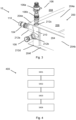
FIG. 1 is a battery comprising an exemplary thermal management arrangement according to an example. -
FIG. 2 is a perspective view of an exemplary thermal management arrangement according to an example. -
FIG. 3 is an exploded perspective view of an exemplary thermal management arrangement according to an example, and -
FIG. 4 in a method for thermal management in a battery pack according to an example. - The detailed description set forth below provides information and examples of the disclosed technology with sufficient detail to enable those skilled in the art to practice the disclosure.
-
FIG. 1 shows abattery 100 comprising an exemplarythermal management arrangement 10 according to an example. Thebattery 100 inFIG. 1 comprises a plurality ofbattery packs FIG. 1 , thebattery 100 is exemplified as comprising twelve battery packs 200, 300 but it could include any number of battery packs. Each battery pack, such as afirst battery pack 200, comprises ahousing 204 for accommodating the battery pack, including a plurality of battery cells. Thehousing 204 comprises fourside sections 204a-d. For clarity, the battery packs 200, 300 are inFIG. 1 illustrated without the battery cells. - The
first battery pack 200 comprises athermal management arrangement 10 which is partly shown inFIG. 1 . Thethermal management arrangement 10 comprises aport arrangement 210 comprising a plurality ofports 212, the ports allowing for a heat-transfer medium to flow from thefirst battery pack 200 to afurther battery pack 300, thus allowing the same heat-transfer medium to be used for more than onebattery pack battery 100. The heat-transfer medium could for example be air, water or any other fluid suitable for transferring heat to and from the battery cells. - The
ports 212 of thethermal management arrangement 10 are in turn fluidically connected to a heat-transfer structure within thebattery pack 200 for allowing the heat-transfer medium to be set into thermal contact with the battery cells therein. The heat-transfer structure is not visible inFIG. 1 but could in one example be cooling channels extending across the top and bottom surfaces of thehousing 204. The heat-transfer structure could also be construed in other ways, such as structures allowing for immersion of the battery cells or as conductive structures arranged between the battery cells. - The
thermal management arrangement 10 further comprises adapters, hose connectors and plugs arranged to be connected to theport arrangement 210 of thebattery pack 200. These will be further explained in relation toFIG. 2 andFIG. 3 . -
FIG. 2 is a perspective view of an exemplarythermal management arrangement 10 according to an example. The thermal management arrangement shown inFIG. 2 comprises aport arrangement 210 comprising a plurality ofports 212a-d arranged in afirst battery pack 200. Arranged to atleast ports 212a-c are members for controlling the flow of heat-transfer medium to, in and from thebattery pack 200. In the example shown inFIG. 2 , ahose connector 106 is connected toport 212a, a (hidden)adapter 104 is connected toport 212b and aplug 108 is connected toport 212c. - The
hose connector 106 allows connection of a heat-transfer medium supply hose to thethermal management arrangement 10. The hose connector thus provides an inlet and/or outlet to thethermal management arrangement 10 where heat-transfer medium from an external source can be introduced to and/or transported away from thethermal management arrangement 10. - The
adapter 104 is arranged to connect theport 212b of thebattery pack 200 to aport 312 of aport arrangement 310 of afurther battery pack 300. Theadapter 104 thus comprises a first side and a second side adapted to be fitted into the ports of the battery packs 200, 300 and a channel extending through the connector to allow the heat-transfer medium to be transferred from thefirst battery pack 200 to thefurther battery pack 300. - The
plug 108 is arranged to stop the flow of heat-transfer medium through theport 212c. The plug is thus used when no flow is desired through a port, such as when the port does neither face any other pack and is nor to be used for supply of heat-transfer medium from a heat-transfer medium source. - In the example of
FIG. 2 a flow of heat-transfer medium would thus be allowed to be supplied through theport 212a, flow throughport 212a and further through theadapter 104 to the inside of thefurther battery pack 300. Additional adapters could be arranged to theporta arrangement 310 of thefurther battery pack 300 to allow a continuation of the flow of heat-transfer medium. - The
hose connector 106, theadapter 104 and theplug 108 are each compatible with allports 212 of thebattery pack 200, and with further ports of further battery packs of thebattery 100, such asfurther battery pack 300. The thermal management arrangement is thus modular, allowing the battery packs 200, 300 to be configured in a large variety of configurations and thus allowing thebattery 100 to be adapted to the application at hand, e.g., based on space limitations or cooling requirements. For example, if it where desired to reduce the height of thebattery 100 shown inFIG. 2 due to space limitation, the battery pack arranged on top of thefurther battery pack 300 could instead be arranged at the same horizontal level as battery packs 200, 300 and be connected toport 212c by exchanging theplug 108 for anadapter 106. -
FIG. 3 is an exploded view of an exemplary thermal management arrangement according to an example.FIG. 3 shows further details of thebattery pack 200, thehose connector 106, theadapter 104 and theplug 108. - As shown in
FIG. 3 , thebattery pack 200 comprises ahousing 204 separating an interior 206 and anexterior 208 of the battery pack. The housing comprises at least twoadjacent side sections 204a-b, atop section 204e and abottom section 204f. Although not shown inFIG. 3 , thehousing 204 also comprisesside sections side sections 204a-b.FIG. 3 further shows aport arrangement 210 comprising afirst port 212a arranged in thefirst side section 204a, asecond port 204b arranged in thesecond side section 204b, athird port 212c arranged in thetop section 204e and a fourth (hidden)port 212d arranged in thebottom section 204f. - In the example shown in
FIG. 3 , anadapter 104 is arranged in thefirst port 212a, aplug 108 is arranged in thesecond port 212b, and ahose connector 106 is arranged in thethird port 212c. The arrangement shown inFIG. 3 is thus at least adapted to receive heat-transfer medium from a supply throughport 212c using thehose connector 106, to stop the flow of heat-transfer medium throughport 212b using theplug 108, and to transport the heat-transfer medium to a further battery pack through theport 212a using theadapter 104. - The
hose connector 106 shown inFIG. 3 comprises aspigot member 106a and a connectingmember 106b. The connectingmember 106b is adapted to be inserted into theports 212 of theport arrangement 210 and is in this case a male connecting member. The connectingmember 106b is provided with a seal member for preventing leakage from theport 212 where thehose connector 106 is arranged. The connectingmember 106b may further comprise a clamping or locking member for securing thehose connector 106 to theport 212. The spigot member106a is any spigot member that would allow a supply or discharge conduit of the application at hand to be connected. In the example ofFIG. 3 , thespigot member 106a is shown as a male spigot member. - The
adapter 104 is inFIG. 3 illustrated as a symmetrical male-male adapter. Thisadapter 104 is constructed to allow a first half to be fully inserted into theport 212a, while the other half is allowed to be fully inserted into a port of a further battery pack 300 (cf.FIG. 2 ). The adapter thus allows the heat-transfer medium to be transported between thepacks - The
adapter 104 further comprisesseal members 110 for preventing leakage of heat-transfer medium where theadapter 104 is arranged. Theseal members 110 is inFIG. 3 illustrated as O-rings. - The
plug 108 inFIG. 3 comprises a male part adapted to be arranged in theport 212b, and for preventing a flow of heat-transfer medium past theplug 108. Theplug 108 is further provided with a seal member for preventing leakage, and with a locking ring for preventing loosening of theplug 108 from the pressure of the heat-transfer medium. The locking ring may be replaced with any other fastener suitable for securing theplug 108 to theport 212b. -
FIG. 4 illustrates amethod 400 for thermal management in abattery pack 200 according to one example. Themethod 400 includes arranging S401 anadapter 104 to afirst port 212a of the battery pack and arranging S402 ahose connector 106 to asecond port 212b of the battery pack. Theadapter 104 and thehose connector 106 are adapted to be interchangeably arranged to thefirst port 212a and thesecond port 212b, meaning that theadapter 104 and thehose connector 106 are constructed so that they could be arranged in both thefirst port 212a and thesecond port 212b. - The
method 400 could further include arranging S403 aplug 108 to athird port 212c of theport arrangement 210, thus hindering a flow of heat-transfer medium through thatport 212c. As with theadapter 104 and thehose connector 106, the plug is constructed such that it could be arranged to any of theports 212a-c. - The
method 400 could further include connecting S404 theadapter 104 to aport 312 of afurther battery pack 300, top allow the heat-transfer medium to flow between the battery packs 200, 300. - Example 1: A thermal management arrangement (10) for a battery pack (200), the arrangement (10) comprising:
- a housing (204) arranged to accommodate the battery pack (200),
- a port arrangement (210) comprising at least one port (212), the port (212) being arranged to allow for a heat-transfer medium to flow between an interior (206) and exterior (208) of the housing (204),
- an adapter (104) arranged to be connected to the port (212) for allowing the heat-transfer medium to flow from the interior (206) of the housing (204) to an interior of a further housing arranged to accommodate a further battery pack, and
- a hose connector (106) arranged to be connected to the port (212) for allowing a heat-transfer medium supply hose to be connected to the port (210).
- Example 2: The arrangement (10) of example 1, further comprising a plug (108) arranged to be connected to the port (212) for preventing the flow of heat-transfer medium through the port (212).
- Example 3: The arrangement (10) of example 1, wherein the housing (204) arranged to accommodate the first battery pack (202) comprises four side sections (204a-d), a top section (204e) and a bottom section (204f), and wherein the port arrangement (210) comprises at least two ports (212a, 212b) arranged to allow the heat-transfer medium to flow through at least two different sections (212a, 212b) of the housing (204).
- Example 4: The arrangement (10) of example 1, wherein the housing (204) arranged to accommodate the battery pack (200) comprises at least four ports (212a-d) arranged to allow the heat-transfer medium to flow through at least four different sections (204a-d) of the housing (204).
- Example 5: The arrangement (10) of example 1, wherein each port (212a-b) is arranged at a location of two adjacent sections (204) where the two adjacent sections (204) form a corner of the housing (204).
- Example 6: The arrangement (10) of example 1, wherein the adapter (104) is a male-male adapter.
- Example 7: The arrangement (10) of example 1, wherein the adapter (104) comprises a seal member (110).
- Example 8: The arrangement (10) of example 1, wherein the seal member (110) is an O-ring.
- Example 9: The arrangement (10) of example 1, wherein the hose connector (106) comprises a spigot member (106a) adapted to be connected to a hose, and a connecting member (106b) adapted to be connected to the port (212), the connecting member being a male connecting member.
- Example 10: The arrangement (10) of example 1, the port arrangement (210) being arranged to form part of the housing (204).
- Example 11: A battery arrangement (100) comprising the thermal management arrangement (10) of any of claims 1-10 wherein the battery arrangement (100) comprises at least said further battery pack (300) arranged to be accommodated in said further housing, said further housing comprising a port arrangement (310), the adapter (104) being arranged to be connected to a port (312) of the port arrangement (310) of said further housing.
- Example 12: A vehicle comprising the thermal management arrangement (10) according to example 1.
- Example 13: A method (400) for thermal management in thermal management arrangement (10) in a battery pack (200), the thermal management arrangement (10) comprising:
- a housing (204) arranged to accommodate the battery pack (200),
- a port arrangement (210) comprising at least one port (212), the port (212) being arranged to allow for a heat-transfer medium to flow between an interior (206) and exterior (208) of the housing (204), the method (400) comprising:
- arranging (S100) an adapter (104) in a first port (212a) of the port arrangement (212) for allowing the heat-transfer medium to flow from the interior region (206) of the first battery pack to an interior region of a further battery pack (300), and
- arranging (S102) a hose connector (106) to a second port (212b) of the port arrangement (212) for allowing for a heat-transfer medium supply hose to be connected to the port (210).
- Example 14: The method (400) of example 13, wherein the method further comprises arranging a plug (108) to a third port (212c) of the port arrangement (212) for preventing the flow of heat-transfer medium through the port (212c).
- Example 15: The method (400) of example 13, wherein the housing (204) arranged to accommodate the first battery pack (200) comprises four side sections (204a-d), a top section (204e) and a bottom section (204f), and wherein the port arrangement (210) comprises at least two ports (212a, 212b) arranged to allow the heat-transfer medium to flow through at least two different sections (212a, 212b) of the housing (204).
- Example 16: The method (400) of example 13, wherein the housing (204) arranged to accommodate the battery pack (200) comprises at least four ports (212a-d) arranged to allow the heat-transfer medium to flow through at least four different sections (204a-d) of the housing (204).
- Example 17: The method (400) of example 13, wherein each port (212a-b) is arranged at a location of two adjacent sections (204) where the two adjacent sections (204) form a corner of the housing (204).
- Example 18: The method (400) of example 13, wherein the adapter (104) is a male-male adapter.
- Example 19: The method (400) of example 13, wherein the hose connector (106) comprises a spigot member adapted to be connected to a hose, and a connecting member adapted to be connected to the port (212), the connecting member being a male connecting member.
- Example 20: The method (400) of example 13, wherein the battery pack (200) is connected to said further battery pack (300), arranged to be accommodated in said further housing, to form a battery arrangement (100), said further housing comprising a port arrangement (310), the adapter (104) being arranged to be connected to a port (312) of the port arrangement (310) of said further housing.
- The terminology used herein is for the purpose of describing particular aspects only and is not intended to be limiting of the disclosure. As used herein, the singular forms "a," "an," and "the" are intended to include the plural forms as well, unless the context clearly indicates otherwise. As used herein, the term "and/or" includes any and all combinations of one or more of the associated listed items. It will be further understood that the terms "comprises," "comprising," "includes," and/or "including" when used herein specify the presence of stated features, integers, actions, steps, operations, elements, and/or components, but do not preclude the presence or addition of one or more other features, integers, actions, steps, operations, elements, components, and/or groups thereof.
- It will be understood that, although the terms first, second, etc., may be used herein to describe various elements, these elements should not be limited by these terms. These terms are only used to distinguish one element from another. For example, a first element could be termed a second element, and, similarly, a second element could be termed a first element without departing from the scope of the present disclosure.
- Relative terms such as "below" or "above" or "upper" or "lower" or "horizontal" or "vertical" may be used herein to describe a relationship of one element to another element as illustrated in the Figures. It will be understood that these terms and those discussed above are intended to encompass different orientations of the device in addition to the orientation depicted in the Figures. It will be understood that when an element is referred to as being "connected" or "coupled" to another element, it can be directly connected or coupled to the other element, or intervening elements may be present. In contrast, when an element is referred to as being "directly connected" or "directly coupled" to another element, there are no intervening elements present.
- Unless otherwise defined, all terms (including technical and scientific terms) used herein have the same meaning as commonly understood by one of ordinary skill in the art to which this disclosure belongs. It will be further understood that terms used herein should be interpreted as having a meaning consistent with their meaning in the context of this specification and the relevant art and will not be interpreted in an idealized or overly formal sense unless expressly so defined herein.
- It is to be understood that the present disclosure is not limited to the aspects described above and illustrated in the drawings; rather, the skilled person will recognize that many changes and modifications may be made within the scope of the present disclosure and appended claims. In the drawings and specification, there have been disclosed aspects for purposes of illustration only and not for purposes of limitation, the scope of the disclosure being set forth in the following claims.
Claims (15)
- A thermal management arrangement (10) for a battery pack (200), the arrangement (10) comprising:a housing (204) arranged to accommodate the battery pack (200),a port arrangement (210) comprising at least one port (212), the port (212) being arranged to allow for a heat-transfer medium to flow between an interior (206) and exterior (208) of the housing (204),an adapter (104) arranged to be connected to the port (212) for allowing the heat-transfer medium to flow from the interior (206) of the housing (204) to an interior of a further housing arranged to accommodate a further battery pack, anda hose connector (106) arranged to be connected to the port (212) for allowing a heat-transfer medium supply hose to be connected to the port (212).
- The thermal management arrangement (10) of claim 1, further comprising a plug (108) arranged to be connected to the port (212) for preventing the flow of heat-transfer medium through the port (212).
- The thermal management arrangement (10) of any of claims 1-2, wherein the housing (204) arranged to accommodate the first battery pack (202) comprises four side sections (204a-d), a top section (204e) and a bottom section (204f), and wherein the port arrangement (210) comprises at least two ports (212a, 212b) arranged to allow the heat-transfer medium to flow through at least two different sections (212a, 212b) of the housing (204).
- The thermal management arrangement (10) of claim 3, wherein the housing (204) arranged to accommodate the battery pack (200) comprises at least four ports (212a-d) arranged to allow the heat-transfer medium to flow through at least four different sections (204a-d) of the housing (204).
- The thermal management arrangement (10) of any of claims 3-4, wherein each port (212a-b) is arranged at a location of two adjacent sections (204) where the two adjacent sections (204) form a corner of the housing (204).
- The thermal management arrangement (10) of any of claims 1-5, wherein the adapter (104) is a male-male adapter.
- The thermal management arrangement (10) of any of claims 1-6, wherein the adapter (104) comprises a seal member (110).
- The thermal management arrangement (10) of claim 7, wherein the seal member (110) is an O-ring.
- The thermal management arrangement (10) of any of claims 1-8, wherein the hose connector (106) comprises a spigot member (106a) adapted to be connected to a hose, and a connecting member (106b) adapted to be connected to the port (212), the connecting member being a male connecting member.
- The thermal management arrangement (10) of any of claims 1-9, the port arrangement (210) being arranged to form part of the housing (204).
- A battery arrangement (100) comprising the thermal management arrangement (10) of any of claims 1-10 wherein the battery arrangement (100) comprises at least said further battery pack (300) arranged to be accommodated in said further housing, said further housing comprising a port arrangement (310), the adapter (104) being arranged to be connected to a port (312) of the port arrangement (310) of said further housing.
- A vehicle comprising the thermal management arrangement (10) according to any of claims 1-11.
- A method (400) for thermal management in a thermal management arrangement (10) in a battery pack (200), the thermal management arrangement (10) comprising:a housing (204) arranged to accommodate the battery pack (200),a port arrangement (210) comprising at least one port (212), the port (212) being arranged to allow for a heat-transfer medium to flow between an interior (206) and exterior (208) of the housing (204), the method (400) comprising:wherein the adapter (104) and the hose connector (106) are adapted to be interchangeably arranged to the first port (212a) and the second port (212b).arranging (S401) an adapter (104) in a first port (212a) of the port arrangement (212) for allowing the heat-transfer medium to flow from the interior region (206) of the first battery pack to an interior region of a further battery pack (300), andarranging (S402) a hose connector (106) to a second port (212b) of the port arrangement (212) for allowing for a heat-transfer medium supply hose to be connected to the port (212b).
- The method (400) of claim 13, wherein the method further comprises arranging (S403) a plug (108) to a third port (212c) of the port arrangement (210) for preventing the flow of heat-transfer medium through the port (212c).
- The method (400) of any of claims 13-14, wherein the housing (204) arranged to accommodate the first battery pack (200) comprises four side sections (204a-d), a top section (204e) and a bottom section (204f), and wherein the port arrangement (210) comprises at least two ports (212a, 212b) arranged to allow the heat-transfer medium to flow through at least two different sections (212a, 212b) of the housing (204).
Priority Applications (2)
| Application Number | Priority Date | Filing Date | Title |
|---|---|---|---|
| EP23206203.4A EP4546521A1 (en) | 2023-10-26 | 2023-10-26 | Arrangement and method for thermal management in a battery pack |
| US18/908,383 US20250140980A1 (en) | 2023-10-26 | 2024-10-07 | Arrangement and method for thermal management in a battery pack |
Applications Claiming Priority (1)
| Application Number | Priority Date | Filing Date | Title |
|---|---|---|---|
| EP23206203.4A EP4546521A1 (en) | 2023-10-26 | 2023-10-26 | Arrangement and method for thermal management in a battery pack |
Publications (1)
| Publication Number | Publication Date |
|---|---|
| EP4546521A1 true EP4546521A1 (en) | 2025-04-30 |
Family
ID=88558514
Family Applications (1)
| Application Number | Title | Priority Date | Filing Date |
|---|---|---|---|
| EP23206203.4A Pending EP4546521A1 (en) | 2023-10-26 | 2023-10-26 | Arrangement and method for thermal management in a battery pack |
Country Status (2)
| Country | Link |
|---|---|
| US (1) | US20250140980A1 (en) |
| EP (1) | EP4546521A1 (en) |
Citations (2)
| Publication number | Priority date | Publication date | Assignee | Title |
|---|---|---|---|---|
| US20210265682A1 (en) * | 2020-02-25 | 2021-08-26 | Samsung Sdi Co., Ltd. | Rechargeable battery pack |
| CN113594581A (en) * | 2021-08-03 | 2021-11-02 | 广州小鹏汽车科技有限公司 | Battery pack and electric automobile |
-
2023
- 2023-10-26 EP EP23206203.4A patent/EP4546521A1/en active Pending
-
2024
- 2024-10-07 US US18/908,383 patent/US20250140980A1/en active Pending
Patent Citations (2)
| Publication number | Priority date | Publication date | Assignee | Title |
|---|---|---|---|---|
| US20210265682A1 (en) * | 2020-02-25 | 2021-08-26 | Samsung Sdi Co., Ltd. | Rechargeable battery pack |
| CN113594581A (en) * | 2021-08-03 | 2021-11-02 | 广州小鹏汽车科技有限公司 | Battery pack and electric automobile |
Also Published As
| Publication number | Publication date |
|---|---|
| US20250140980A1 (en) | 2025-05-01 |
Similar Documents
| Publication | Publication Date | Title |
|---|---|---|
| JP7359904B2 (en) | Refrigerant distributor for battery module housing and its manufacturing method | |
| US11984572B2 (en) | Battery cooling system | |
| CN114867980A (en) | Thermal management system for electrical components | |
| CN115149155A (en) | Battery liquid cooling plate system | |
| US12294072B2 (en) | Cell pack thermal management apparatus and method | |
| WO2025166902A1 (en) | Battery and electrical apparatus | |
| US12583303B2 (en) | Bulkhead fitting assembly | |
| EP4546521A1 (en) | Arrangement and method for thermal management in a battery pack | |
| CN220303936U (en) | Hydraulic module and heat pump system | |
| CN220021366U (en) | Energy storage module and energy storage system comprising same | |
| CN221574045U (en) | Battery packs and outdoor walking equipment | |
| CN218586123U (en) | Battery package casing and battery package of integrated liquid cooling | |
| CN216288616U (en) | Casing part of battery box and battery box | |
| WO2025167049A1 (en) | Battery and electrical apparatus | |
| US12109912B2 (en) | Manifold bracket | |
| CN217672250U (en) | Trade electric interface, trade electric device and vehicle | |
| CN113566602A (en) | Heat exchanger, battery system and vehicle | |
| CN223450996U (en) | An energy storage device | |
| CN216015431U (en) | Fluid transmission structure of fuel cell and fuel cell | |
| CN220963475U (en) | Battery cell, battery pack and energy storage system | |
| CN220042067U (en) | Energy storage module and energy storage system comprising same | |
| CN222638935U (en) | Liquid cooling pipeline system and energy storage converter | |
| CN223582995U (en) | Scalable devices for flow batteries | |
| US20260009590A1 (en) | Heat exchanger assembly | |
| CN113113712A (en) | Battery pack and electric equipment |
Legal Events
| Date | Code | Title | Description |
|---|---|---|---|
| PUAI | Public reference made under article 153(3) epc to a published international application that has entered the european phase |
Free format text: ORIGINAL CODE: 0009012 |
|
| STAA | Information on the status of an ep patent application or granted ep patent |
Free format text: STATUS: THE APPLICATION HAS BEEN PUBLISHED |
|
| AK | Designated contracting states |
Kind code of ref document: A1 Designated state(s): AL AT BE BG CH CY CZ DE DK EE ES FI FR GB GR HR HU IE IS IT LI LT LU LV MC ME MK MT NL NO PL PT RO RS SE SI SK SM TR |
|
| STAA | Information on the status of an ep patent application or granted ep patent |
Free format text: STATUS: REQUEST FOR EXAMINATION WAS MADE |
|
| 17P | Request for examination filed |
Effective date: 20251027 |