EP4546513A1 - Encapsulation film, electrochemical device, and electronic device - Google Patents
Encapsulation film, electrochemical device, and electronic device Download PDFInfo
- Publication number
- EP4546513A1 EP4546513A1 EP22947387.1A EP22947387A EP4546513A1 EP 4546513 A1 EP4546513 A1 EP 4546513A1 EP 22947387 A EP22947387 A EP 22947387A EP 4546513 A1 EP4546513 A1 EP 4546513A1
- Authority
- EP
- European Patent Office
- Prior art keywords
- thickness
- layer
- metal layer
- encapsulation film
- mpa
- Prior art date
- Legal status (The legal status is an assumption and is not a legal conclusion. Google has not performed a legal analysis and makes no representation as to the accuracy of the status listed.)
- Pending
Links
Images
Classifications
-
- H—ELECTRICITY
- H01—ELECTRIC ELEMENTS
- H01M—PROCESSES OR MEANS, e.g. BATTERIES, FOR THE DIRECT CONVERSION OF CHEMICAL ENERGY INTO ELECTRICAL ENERGY
- H01M50/00—Constructional details or processes of manufacture of the non-active parts of electrochemical cells other than fuel cells, e.g. hybrid cells
- H01M50/10—Primary casings; Jackets or wrappings
- H01M50/116—Primary casings; Jackets or wrappings characterised by the material
- H01M50/121—Organic material
-
- B—PERFORMING OPERATIONS; TRANSPORTING
- B32—LAYERED PRODUCTS
- B32B—LAYERED PRODUCTS, i.e. PRODUCTS BUILT-UP OF STRATA OF FLAT OR NON-FLAT, e.g. CELLULAR OR HONEYCOMB, FORM
- B32B15/00—Layered products comprising a layer of metal
- B32B15/04—Layered products comprising a layer of metal comprising metal as the main or only constituent of a layer, which is next to another layer of the same or of a different material
- B32B15/08—Layered products comprising a layer of metal comprising metal as the main or only constituent of a layer, which is next to another layer of the same or of a different material of synthetic resin
-
- B—PERFORMING OPERATIONS; TRANSPORTING
- B32—LAYERED PRODUCTS
- B32B—LAYERED PRODUCTS, i.e. PRODUCTS BUILT-UP OF STRATA OF FLAT OR NON-FLAT, e.g. CELLULAR OR HONEYCOMB, FORM
- B32B15/00—Layered products comprising a layer of metal
- B32B15/04—Layered products comprising a layer of metal comprising metal as the main or only constituent of a layer, which is next to another layer of the same or of a different material
- B32B15/08—Layered products comprising a layer of metal comprising metal as the main or only constituent of a layer, which is next to another layer of the same or of a different material of synthetic resin
- B32B15/082—Layered products comprising a layer of metal comprising metal as the main or only constituent of a layer, which is next to another layer of the same or of a different material of synthetic resin comprising vinyl resins; comprising acrylic resins
-
- B—PERFORMING OPERATIONS; TRANSPORTING
- B32—LAYERED PRODUCTS
- B32B—LAYERED PRODUCTS, i.e. PRODUCTS BUILT-UP OF STRATA OF FLAT OR NON-FLAT, e.g. CELLULAR OR HONEYCOMB, FORM
- B32B15/00—Layered products comprising a layer of metal
- B32B15/04—Layered products comprising a layer of metal comprising metal as the main or only constituent of a layer, which is next to another layer of the same or of a different material
- B32B15/08—Layered products comprising a layer of metal comprising metal as the main or only constituent of a layer, which is next to another layer of the same or of a different material of synthetic resin
- B32B15/085—Layered products comprising a layer of metal comprising metal as the main or only constituent of a layer, which is next to another layer of the same or of a different material of synthetic resin comprising polyolefins
-
- B—PERFORMING OPERATIONS; TRANSPORTING
- B32—LAYERED PRODUCTS
- B32B—LAYERED PRODUCTS, i.e. PRODUCTS BUILT-UP OF STRATA OF FLAT OR NON-FLAT, e.g. CELLULAR OR HONEYCOMB, FORM
- B32B15/00—Layered products comprising a layer of metal
- B32B15/04—Layered products comprising a layer of metal comprising metal as the main or only constituent of a layer, which is next to another layer of the same or of a different material
- B32B15/08—Layered products comprising a layer of metal comprising metal as the main or only constituent of a layer, which is next to another layer of the same or of a different material of synthetic resin
- B32B15/095—Layered products comprising a layer of metal comprising metal as the main or only constituent of a layer, which is next to another layer of the same or of a different material of synthetic resin comprising polyurethanes
-
- B—PERFORMING OPERATIONS; TRANSPORTING
- B32—LAYERED PRODUCTS
- B32B—LAYERED PRODUCTS, i.e. PRODUCTS BUILT-UP OF STRATA OF FLAT OR NON-FLAT, e.g. CELLULAR OR HONEYCOMB, FORM
- B32B15/00—Layered products comprising a layer of metal
- B32B15/18—Layered products comprising a layer of metal comprising iron or steel
-
- B—PERFORMING OPERATIONS; TRANSPORTING
- B32—LAYERED PRODUCTS
- B32B—LAYERED PRODUCTS, i.e. PRODUCTS BUILT-UP OF STRATA OF FLAT OR NON-FLAT, e.g. CELLULAR OR HONEYCOMB, FORM
- B32B15/00—Layered products comprising a layer of metal
- B32B15/20—Layered products comprising a layer of metal comprising aluminium or copper
-
- B—PERFORMING OPERATIONS; TRANSPORTING
- B32—LAYERED PRODUCTS
- B32B—LAYERED PRODUCTS, i.e. PRODUCTS BUILT-UP OF STRATA OF FLAT OR NON-FLAT, e.g. CELLULAR OR HONEYCOMB, FORM
- B32B27/00—Layered products comprising a layer of synthetic resin
- B32B27/30—Layered products comprising a layer of synthetic resin comprising vinyl (co)polymers; comprising acrylic (co)polymers
- B32B27/302—Layered products comprising a layer of synthetic resin comprising vinyl (co)polymers; comprising acrylic (co)polymers comprising aromatic vinyl (co)polymers, e.g. styrenic (co)polymers
-
- B—PERFORMING OPERATIONS; TRANSPORTING
- B32—LAYERED PRODUCTS
- B32B—LAYERED PRODUCTS, i.e. PRODUCTS BUILT-UP OF STRATA OF FLAT OR NON-FLAT, e.g. CELLULAR OR HONEYCOMB, FORM
- B32B27/00—Layered products comprising a layer of synthetic resin
- B32B27/30—Layered products comprising a layer of synthetic resin comprising vinyl (co)polymers; comprising acrylic (co)polymers
- B32B27/304—Layered products comprising a layer of synthetic resin comprising vinyl (co)polymers; comprising acrylic (co)polymers comprising vinyl halide (co)polymers, e.g. PVC, PVDC, PVF, PVDF
-
- B—PERFORMING OPERATIONS; TRANSPORTING
- B32—LAYERED PRODUCTS
- B32B—LAYERED PRODUCTS, i.e. PRODUCTS BUILT-UP OF STRATA OF FLAT OR NON-FLAT, e.g. CELLULAR OR HONEYCOMB, FORM
- B32B27/00—Layered products comprising a layer of synthetic resin
- B32B27/32—Layered products comprising a layer of synthetic resin comprising polyolefins
-
- B—PERFORMING OPERATIONS; TRANSPORTING
- B32—LAYERED PRODUCTS
- B32B—LAYERED PRODUCTS, i.e. PRODUCTS BUILT-UP OF STRATA OF FLAT OR NON-FLAT, e.g. CELLULAR OR HONEYCOMB, FORM
- B32B27/00—Layered products comprising a layer of synthetic resin
- B32B27/40—Layered products comprising a layer of synthetic resin comprising polyurethanes
-
- B—PERFORMING OPERATIONS; TRANSPORTING
- B32—LAYERED PRODUCTS
- B32B—LAYERED PRODUCTS, i.e. PRODUCTS BUILT-UP OF STRATA OF FLAT OR NON-FLAT, e.g. CELLULAR OR HONEYCOMB, FORM
- B32B7/00—Layered products characterised by the relation between layers; Layered products characterised by the relative orientation of features between layers, or by the relative values of a measurable parameter between layers, i.e. products comprising layers having different physical, chemical or physicochemical properties; Layered products characterised by the interconnection of layers
- B32B7/04—Interconnection of layers
- B32B7/12—Interconnection of layers using interposed adhesives or interposed materials with bonding properties
-
- H—ELECTRICITY
- H01—ELECTRIC ELEMENTS
- H01M—PROCESSES OR MEANS, e.g. BATTERIES, FOR THE DIRECT CONVERSION OF CHEMICAL ENERGY INTO ELECTRICAL ENERGY
- H01M10/00—Secondary cells; Manufacture thereof
- H01M10/05—Accumulators with non-aqueous electrolyte
- H01M10/052—Li-accumulators
- H01M10/0525—Rocking-chair batteries, i.e. batteries with lithium insertion or intercalation in both electrodes; Lithium-ion batteries
-
- H—ELECTRICITY
- H01—ELECTRIC ELEMENTS
- H01M—PROCESSES OR MEANS, e.g. BATTERIES, FOR THE DIRECT CONVERSION OF CHEMICAL ENERGY INTO ELECTRICAL ENERGY
- H01M50/00—Constructional details or processes of manufacture of the non-active parts of electrochemical cells other than fuel cells, e.g. hybrid cells
- H01M50/10—Primary casings; Jackets or wrappings
-
- H—ELECTRICITY
- H01—ELECTRIC ELEMENTS
- H01M—PROCESSES OR MEANS, e.g. BATTERIES, FOR THE DIRECT CONVERSION OF CHEMICAL ENERGY INTO ELECTRICAL ENERGY
- H01M50/00—Constructional details or processes of manufacture of the non-active parts of electrochemical cells other than fuel cells, e.g. hybrid cells
- H01M50/10—Primary casings; Jackets or wrappings
- H01M50/102—Primary casings; Jackets or wrappings characterised by their shape or physical structure
- H01M50/105—Pouches or flexible bags
-
- H—ELECTRICITY
- H01—ELECTRIC ELEMENTS
- H01M—PROCESSES OR MEANS, e.g. BATTERIES, FOR THE DIRECT CONVERSION OF CHEMICAL ENERGY INTO ELECTRICAL ENERGY
- H01M50/00—Constructional details or processes of manufacture of the non-active parts of electrochemical cells other than fuel cells, e.g. hybrid cells
- H01M50/10—Primary casings; Jackets or wrappings
- H01M50/116—Primary casings; Jackets or wrappings characterised by the material
-
- H—ELECTRICITY
- H01—ELECTRIC ELEMENTS
- H01M—PROCESSES OR MEANS, e.g. BATTERIES, FOR THE DIRECT CONVERSION OF CHEMICAL ENERGY INTO ELECTRICAL ENERGY
- H01M50/00—Constructional details or processes of manufacture of the non-active parts of electrochemical cells other than fuel cells, e.g. hybrid cells
- H01M50/10—Primary casings; Jackets or wrappings
- H01M50/116—Primary casings; Jackets or wrappings characterised by the material
- H01M50/117—Inorganic material
- H01M50/119—Metals
-
- H—ELECTRICITY
- H01—ELECTRIC ELEMENTS
- H01M—PROCESSES OR MEANS, e.g. BATTERIES, FOR THE DIRECT CONVERSION OF CHEMICAL ENERGY INTO ELECTRICAL ENERGY
- H01M50/00—Constructional details or processes of manufacture of the non-active parts of electrochemical cells other than fuel cells, e.g. hybrid cells
- H01M50/10—Primary casings; Jackets or wrappings
- H01M50/116—Primary casings; Jackets or wrappings characterised by the material
- H01M50/124—Primary casings; Jackets or wrappings characterised by the material having a layered structure
-
- H—ELECTRICITY
- H01—ELECTRIC ELEMENTS
- H01M—PROCESSES OR MEANS, e.g. BATTERIES, FOR THE DIRECT CONVERSION OF CHEMICAL ENERGY INTO ELECTRICAL ENERGY
- H01M50/00—Constructional details or processes of manufacture of the non-active parts of electrochemical cells other than fuel cells, e.g. hybrid cells
- H01M50/10—Primary casings; Jackets or wrappings
- H01M50/116—Primary casings; Jackets or wrappings characterised by the material
- H01M50/124—Primary casings; Jackets or wrappings characterised by the material having a layered structure
- H01M50/126—Primary casings; Jackets or wrappings characterised by the material having a layered structure comprising three or more layers
- H01M50/129—Primary casings; Jackets or wrappings characterised by the material having a layered structure comprising three or more layers with two or more layers of only organic material
-
- H—ELECTRICITY
- H01—ELECTRIC ELEMENTS
- H01M—PROCESSES OR MEANS, e.g. BATTERIES, FOR THE DIRECT CONVERSION OF CHEMICAL ENERGY INTO ELECTRICAL ENERGY
- H01M50/00—Constructional details or processes of manufacture of the non-active parts of electrochemical cells other than fuel cells, e.g. hybrid cells
- H01M50/10—Primary casings; Jackets or wrappings
- H01M50/131—Primary casings; Jackets or wrappings characterised by physical properties, e.g. gas permeability, size or heat resistance
- H01M50/133—Thickness
-
- H—ELECTRICITY
- H01—ELECTRIC ELEMENTS
- H01M—PROCESSES OR MEANS, e.g. BATTERIES, FOR THE DIRECT CONVERSION OF CHEMICAL ENERGY INTO ELECTRICAL ENERGY
- H01M50/00—Constructional details or processes of manufacture of the non-active parts of electrochemical cells other than fuel cells, e.g. hybrid cells
- H01M50/10—Primary casings; Jackets or wrappings
- H01M50/14—Primary casings; Jackets or wrappings for protecting against damage caused by external factors
-
- B—PERFORMING OPERATIONS; TRANSPORTING
- B32—LAYERED PRODUCTS
- B32B—LAYERED PRODUCTS, i.e. PRODUCTS BUILT-UP OF STRATA OF FLAT OR NON-FLAT, e.g. CELLULAR OR HONEYCOMB, FORM
- B32B2307/00—Properties of the layers or laminate
- B32B2307/50—Properties of the layers or laminate having particular mechanical properties
- B32B2307/54—Yield strength; Tensile strength
-
- B—PERFORMING OPERATIONS; TRANSPORTING
- B32—LAYERED PRODUCTS
- B32B—LAYERED PRODUCTS, i.e. PRODUCTS BUILT-UP OF STRATA OF FLAT OR NON-FLAT, e.g. CELLULAR OR HONEYCOMB, FORM
- B32B2307/00—Properties of the layers or laminate
- B32B2307/50—Properties of the layers or laminate having particular mechanical properties
- B32B2307/58—Cuttability
- B32B2307/581—Resistant to cut
-
- B—PERFORMING OPERATIONS; TRANSPORTING
- B32—LAYERED PRODUCTS
- B32B—LAYERED PRODUCTS, i.e. PRODUCTS BUILT-UP OF STRATA OF FLAT OR NON-FLAT, e.g. CELLULAR OR HONEYCOMB, FORM
- B32B2307/00—Properties of the layers or laminate
- B32B2307/70—Other properties
- B32B2307/732—Dimensional properties
- B32B2307/737—Dimensions, e.g. volume or area
- B32B2307/7375—Linear, e.g. length, distance or width
- B32B2307/7376—Thickness
-
- B—PERFORMING OPERATIONS; TRANSPORTING
- B32—LAYERED PRODUCTS
- B32B—LAYERED PRODUCTS, i.e. PRODUCTS BUILT-UP OF STRATA OF FLAT OR NON-FLAT, e.g. CELLULAR OR HONEYCOMB, FORM
- B32B2457/00—Electrical equipment
- B32B2457/10—Batteries
-
- Y—GENERAL TAGGING OF NEW TECHNOLOGICAL DEVELOPMENTS; GENERAL TAGGING OF CROSS-SECTIONAL TECHNOLOGIES SPANNING OVER SEVERAL SECTIONS OF THE IPC; TECHNICAL SUBJECTS COVERED BY FORMER USPC CROSS-REFERENCE ART COLLECTIONS [XRACs] AND DIGESTS
- Y02—TECHNOLOGIES OR APPLICATIONS FOR MITIGATION OR ADAPTATION AGAINST CLIMATE CHANGE
- Y02E—REDUCTION OF GREENHOUSE GAS [GHG] EMISSIONS, RELATED TO ENERGY GENERATION, TRANSMISSION OR DISTRIBUTION
- Y02E60/00—Enabling technologies; Technologies with a potential or indirect contribution to GHG emissions mitigation
- Y02E60/10—Energy storage using batteries
Definitions
- This application relates to the field of electrochemical energy storage, and specifically to an encapsulation film, an electrochemical device, and an electronic device.
- Encapsulation bags made of encapsulation film are essential components of lithium-ion batteries, and play a crucial role in isolating air and moisture and protecting the internal electrode assembly from damage.
- Aluminum-plastic films are currently the most common and mature encapsulation bags, and have been widely used due to their excellent encapsulation performance.
- the aluminum-plastic film is usually made with a thicker metal layer and nylon layer to enhance puncture resistance strength.
- This design achieves a relatively high puncture resistance strength but also results in a loss of volumetric energy density for the lithium-ion battery. Therefore, further improvements in this regard are expected.
- the encapsulation film includes: an inner layer, where the inner layer includes a thermoplastic resin; an outer layer, where the outer layer includes a thermosetting resin; and a metal layer, where the metal layer is located between the inner layer and the outer layer, the metal layer includes at least one of stainless steel, titanium alloy, or nickel alloy, a thickness of the metal layer is 10 ⁇ m to 60 ⁇ m, and a tensile strength of the metal layer is 300 MPa to 2000 MPa; where a ratio of a thickness of the inner layer to the thickness of the metal layer is 0.6 to 3.
- the thickness of the metal layer is 30 ⁇ m to 40 ⁇ m. In some embodiments, the ratio of the thickness of the inner layer to the thickness of the metal layer is 0.6 to 2. In some embodiments, a thickness of the outer layer is 1 ⁇ m to 10 ⁇ m. In some embodiments, an elongation at break of the metal layer is 10% to 45%.
- the thermoplastic resin includes at least one of polyethylene, polyvinyl chloride, polypropylene, or polystyrene. In some embodiments, the thermosetting resin includes at least one of polyurethane or polyacrylate. In some embodiments, the encapsulation film further includes an adhesive layer, where the adhesive layer is located between the inner layer and the metal layer.
- the adhesive layer includes at least one of styrene-butadiene rubber, polyacrylic acid, polyacrylate, polyimide, polyamide-imide, polyvinylidene fluoride, polyvinylidene difluoride, polytetrafluoroethylene, water-based acrylic resin, or polyvinyl formal.
- a thickness of the encapsulation film is 20 ⁇ m to 130 ⁇ m, and a puncture resistance strength of the encapsulation film is 30 N to 70 N.
- An embodiment of this application further provides an electrochemical device, including the foregoing encapsulation film.
- An embodiment of this application further provides an electronic device, including the foregoing electrochemical device.
- the metal layer includes at least one of stainless steel, titanium alloy, or nickel alloy
- the tensile strength of the metal layer is 300 MPa to 2000 MPa
- the ratio of the thickness of the inner layer to the thickness of the metal layer is 0.6 to 3. This can achieve a relatively high puncture resistance strength under a condition that the thickness of the encapsulation film is relatively thin, thereby enhancing the puncture resistance strength of the electrochemical device while reducing the adverse impact on the energy density of the electrochemical device.
- a three-layer structure including a polyester layer, a metal layer, and a hot-melt resin layer is used, which reduces the use of intermediate binders, thereby reducing a total thickness of the encapsulation film and decreasing the energy density loss of the lithium-ion battery.
- a thickness of the metal layer is required to be above 30 ⁇ m, and an overall thickness of the encapsulation film is below 140 ⁇ m, which still does not significantly decrease the energy density loss of the lithium-ion battery.
- a three-layer structure including a polyamide layer, a metal layer, and a hot-melt resin layer is used, where a thickness of the polyamide layer is required to be above 10 ⁇ m, a thickness of the metal layer is required to be above 36 ⁇ m, and a total thickness of the encapsulation film is above 83 ⁇ m.
- the total thickness of this designed encapsulation film is still relatively large, and to ensure it has a relatively high puncture resistance strength, the thickness of the metal layer is also strictly required, which still does not significantly decrease the energy density loss of the lithium-ion battery.
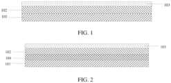
- FIG. 1 is a schematic cross-sectional view of an encapsulation film according to some embodiments of this application.
- the encapsulation film includes an inner layer 101, a metal layer 102, and an outer layer 103, where the metal layer 102 is located between the inner layer 101 and the outer layer 103.
- the inner layer 101, the metal layer 102, and the outer layer 103 may be bonded together through lamination, but this is merely exemplary and not intended to be limiting.
- the inner layer 101 includes a thermoplastic resin.
- the outer layer 103 includes a thermosetting resin, so the outer layer 103 may be configured to suppress the swelling and deformation of an electrode assembly inside.
- the metal layer 102 includes at least one of stainless steel, titanium alloy, or nickel alloy. These materials have relatively high strength, which helps reduce the thickness of the used metal layer 102. In some embodiments, the thickness of the metal layer 102 is 10 ⁇ m to 60 ⁇ m. If the thickness of the metal layer 102 is too small, the puncture resistance strength of the encapsulation film is small; and if the thickness of the metal layer 102 is too large, it does not help increase the energy density of the electrochemical device.
- the thickness of the metal layer 102 is 30 ⁇ m to 40 ⁇ m. In some embodiments, the thickness of the metal layer 102 may be 10 ⁇ m, 20 ⁇ m, 30 ⁇ m, 40 ⁇ m, 50 ⁇ m, 60 ⁇ m, or other suitable values.
- the tensile strength of the metal layer 102 is 300 MPa to 2000 MPa. If the tensile strength of the metal layer 102 is too small, the strength of the metal layer 102 is low, resulting in insufficient puncture resistance strength of the encapsulation film; and if the tensile strength of the metal layer 102 is too large, the ductility of the metal layer 102 is poor, exhibiting a certain brittleness, which also causes a decrease in the puncture resistance strength of the encapsulation film. In some embodiments, the tensile strength of the metal layer 102 may be 300 MPa, 500 MPa, 800 MPa, 1000 MPa, 1200 MPa, 1500 MPa, 1800 MPa, 2000 MPa, or other suitable values.
- the ratio of the thickness of the inner layer 101 to the thickness of the metal layer 102 is 0.6 to 3. In some embodiments, the ratio of the thickness of the inner layer 101 to the thickness of the metal layer 102 is 0.6 to 2. If the ratio of the thickness of the inner layer 101 to the thickness of the metal layer 102 is too small, because a thickness of the thermoplastic resin layer is too thin, and the inner layer 101 also provides some mechanical strength, the overall puncture resistance strength of the encapsulation film is insufficient; and if the ratio of the thickness of the inner layer 101 to the thickness of the metal layer 102 is too large, a thickness of the thermoplastic resin layer is too large, resulting in a larger overall thickness of the encapsulation film, and although it has strong puncture resistance strength, it has an adverse impact on the energy density of the electrochemical device. In some embodiments, the ratio of the thickness of the inner layer 101 to the thickness of the metal layer 102 may be 0.6, 1, 1.2, 1.5, 2, 2.5, 3, or other suitable values.
- the metal layer includes at least one of stainless steel, titanium alloy, or nickel alloy, the tensile strength of the metal layer is 300 MPa to 2000 MPa, the thickness of the metal layer is 10 ⁇ m to 60 ⁇ m, and the ratio of the thickness of the inner layer to the thickness of the metal layer is 0.6 to 3. This can achieve a relatively high puncture resistance strength under a condition that the thickness of the encapsulation film is relatively thin, thereby enhancing the puncture resistance strength of the electrochemical device while reducing the adverse impact on the energy density of the electrochemical device.
- the overall thickness of the encapsulation film of this application is significantly reduced, and the puncture resistance strength can be maintained or even improved compared with thicker aluminum-plastic films, thereby improving the overall volumetric energy density and safety performance of the lithium-ion battery.
- the thickness of the outer layer 103 is 1 ⁇ m to 10 ⁇ m.
- the outer layer 103 can protect the metal layer 102 and form good insulation performance with the external environment. If the thickness of the outer layer 103 is too small, the outer layer 103 is easily scratched, exposing the metal layer 102 and resulting in poor external insulation; and if the thickness of the outer layer 103 is too large, the overall volumetric energy density of the resulting electrochemical device is affected.
- the thickness of the outer layer 103 may be 1 ⁇ m, 3 ⁇ m, 5 ⁇ m, 8 ⁇ m, 10 ⁇ m, or other suitable values.
- the elongation at break of the metal layer 102 is 10% to 45%. If the elongation at break of the metal layer 102 is too small, the ductility of the metal layer 102 is poor; and if the elongation at break of the metal layer 102 is too large, the structural stability of the encapsulation film is poor. In some embodiments, the elongation at break of the metal layer 102 may be 10%, 15%, 20%, 25%, 30%, 35%, 40%, 45%, 50%, or other suitable values.
- the thermoplastic resin includes at least one of polyethylene, polyvinyl chloride, polypropylene, or polystyrene. These thermoplastic resin materials allow the inner layer 101 to be heat-sealed and provide good sealing performance.
- the inner layer 101 may use any suitable material commonly used for the inner layer of encapsulation films in the field. It should be understood that when the encapsulation film is made into an encapsulation bag to accommodate an electrode assembly, the inner layer 101 is close to the electrode assembly, so it is called the inner layer, while the outer layer 103 is farther from the electrode assembly, so it is called the outer layer.
- the thermosetting resin includes at least one of polyurethane or polyacrylate. In this application, a thinner polyurethane layer is used to replace the existing mature polyester or polyamide insulation layer of the aluminum-plastic film outer layer, ensuring good external insulation performance.
- FIG. 2 is a schematic cross-sectional view of an encapsulation film according to some other embodiments of this application.
- the encapsulation film further includes an adhesive layer 104, where the adhesive layer 104 is located between the inner layer 101 and the metal layer 102.
- the adhesive layer 104 is served as an adhesive between the inner layer 101 and the metal layer 102.
- the adhesive layer 104 includes at least one of styrene-butadiene rubber, polyacrylic acid, polyacrylate, polyimide, polyamide-imide, polyvinylidene fluoride, polyvinylidene difluoride, polytetrafluoroethylene, water-based acrylic resin, or polyvinyl formal.
- the thickness of the encapsulation film is 20 ⁇ m to 130 ⁇ m. Using the encapsulation film in this thickness range not only can meet the requirements for puncture resistance strength of the encapsulation film, but also can reduce the adverse impact on the energy density of the electrochemical device. In some embodiments, the thickness of the encapsulation film is 20 ⁇ m, 30 ⁇ m, 40 ⁇ m, 50 ⁇ m, 60 ⁇ m, 70 ⁇ m, 80 ⁇ m, 90 ⁇ m, 100 ⁇ m, 110 ⁇ m, 120 ⁇ m, 130 ⁇ m, or other suitable values. In some embodiments, the puncture resistance strength of the encapsulation film is 30 N to 70 N. This not only can meet the requirements for puncture resistance strength of the encapsulation film, but also can avoid unnecessarily increasing the thickness of the encapsulation film.
- the electrode assembly is sealed by encapsulation bags formed by the encapsulation film, that is, the electrode assembly is located in an accommodating cavity formed by the encapsulation film.
- the electrode assembly includes a positive electrode plate, a negative electrode plate, and a separator located between the positive electrode plate and the negative electrode plate.
- the positive electrode plate includes a positive electrode current collector and a positive electrode active material layer located on the positive electrode current collector. In some embodiments, the positive electrode active material layer is located on one side or two sides of the positive electrode current collector. In some embodiments, the positive electrode active material layer includes a positive electrode active material. In some embodiments, the positive electrode active material includes at least one of lithium cobaltate, lithium nickel cobalt manganese oxide, lithium nickel cobalt aluminate, or lithium manganate. In some embodiments, the positive electrode active material layer may further include a conductive agent.
- the conductive agent in the positive electrode active material layer may include at least one of conductive carbon black, Ketjen black, laminated graphite, graphene, carbon nanotubes, or carbon fiber.
- the positive electrode active material layer may further include a binder.
- the binder in the positive electrode active material layer may include at least one of carboxymethyl cellulose (CMC), polyacrylic acid, polyvinylpyrrolidone, polyaniline, polyimide, polyamideimide, polysiloxane, styrene-butadiene rubber, epoxy resin, polyester resin, polyurethane resin, or polyfluorene.
- CMC carboxymethyl cellulose
- a mass ratio of the positive electrode active material, conductive agent, and binder in the positive electrode active material layer may be (80-99):(0.1-10):(0.1-10).
- a thickness of the positive electrode active material layer may be 10 ⁇ m to 200 ⁇ m. It should be understood that the foregoing description is merely an example, and the positive electrode active material layer of the positive electrode may use any other appropriate materials, thicknesses, and mass ratios.
- the positive electrode current collector may be Al foil, or certainly may be other current collectors commonly used in the art.
- a thickness of the positive electrode current collector may be 1 ⁇ m to 100 ⁇ m.
- the positive electrode active material layer may be applied only on part of the positive electrode current collector.
- the negative electrode plate includes a negative electrode current collector and a negative electrode active material layer located on the negative electrode current collector. In some embodiments, the negative electrode active material layer is located on one side or two sides of the negative electrode current collector. In some embodiments, the negative electrode active material layer includes a negative electrode active material, where the negative electrode active material may include at least one of graphite, hard carbon, silicon, silicon monoxide, or organosilicon. In some embodiments, the negative electrode active material layer may further include a conductive agent and a binder. In some embodiments, the conductive agent in the negative electrode active material layer may include at least one of conductive carbon black, Ketjen black, laminated graphite, graphene, carbon nanotubes, or carbon fiber.
- the binder in the negative electrode active material layer may include at least one of carboxymethyl cellulose (CMC), polyacrylic acid, polyvinylpyrrolidone, polyaniline, polyimide, polyamideimide, polysiloxane, styrene-butadiene rubber, epoxy resin, polyester resin, polyurethane resin, or polyfluorene.
- a mass ratio of the negative electrode active material, the conductive agent, and the binder in the negative electrode active material layer may be (80-98):(0.1-10):(0.1-10). It should be understood that the foregoing description is only exemplary. Any other appropriate materials and mass ratios may be used.
- the negative electrode current collector may be at least one of a copper foil current collector, a nickel foil current collector, or a carbon-based current collector.
- a separator includes at least one of polyethylene, polypropylene, polyvinylidene fluoride, polyethylene terephthalate, polyimide, or aramid.
- polyethylene includes at least one of high-density polyethylene, low-density polyethylene, or ultra-high-molecular-weight polyethylene.
- polyethylene and polypropylene have a good effect on preventing short circuits and can enhance stability of a battery through a shutdown effect.
- a thickness of the separator approximately ranges from 5 ⁇ m to 50 ⁇ m.
- the separator may further include a porous layer on its surface.
- the porous layer is disposed on at least one surface of a matrix of the separator, and the porous layer includes inorganic particles and a binder, where the inorganic particles are selected from at least one of aluminum oxide (Al 2 O 3 ), silicon dioxide (SiO 2 ), magnesium oxide (MgO), titanium oxide (TiO 2 ), hafnium dioxide (HfO 2 ), stannic oxide (SnO 2 ), cerium dioxide (CeO 2 ), nickel oxide (NiO), zinc oxide (ZnO), calcium oxide (CaO), zirconium dioxide (ZrO 2 ), yttrium oxide (Y 2 O 3 ), silicon carbide (SiC), boehmite, aluminum hydroxide, magnesium hydroxide, calcium hydroxide, or barium sulfate.
- Al 2 O 3 aluminum oxide
- SiO 2 silicon dioxide
- MgO magnesium oxide
- TiO 2 titanium oxide
- HfO 2
- the separator has a pore diameter within a range of approximately 0.01 ⁇ m to 1 ⁇ m.
- the binder of the porous layer is selected from at least one of polyvinylidene fluoride, a vinylidene fluoridehexafluoropropylene copolymer, polyamide, polyacrylonitrile, polyacrylate, polyacrylic acid, polyacrylate, sodium carboxymethyl cellulose, polyvinylpyrrolidone, polyvinyl ether, polymethyl methacrylate, polytetrafluoroethylene, or polyhexafluoropropylene.
- the porous layer on the surface of the separator can improve heat resistance, oxidation resistance, and electrolyte infiltration performance of the separator, and enhance adhesion between the separator and the electrode plate.
- the electrode assembly of the electrochemical device is a wound electrode assembly, a laminated electrode assembly, or a folded electrode assembly.
- the positive electrode plate and/or negative electrode plate of the electrochemical device may be a multi-layer structure formed through winding or lamination, or may be a single-layer structure formed by stacking a single positive electrode plate, a separator, and a single negative electrode plate.
- the electrochemical device includes a lithium-ion battery but this application is not limited thereto.
- the electrochemical device may further include an electrolyte.
- the electrolyte may be one or more of gel electrolyte, solid electrolyte, and liquid electrolyte, and the liquid electrolyte includes a lithium salt and a non-aqueous solvent.
- the lithium salt is selected from one or more of LiPF 6 , LiBF 4 , LiAsF 6 , LiClO 4 , LiB(C 6 H 5 ) 4 , LiCH 3 SO 3 , LiCF 3 SO 3 , LiN(SO 2 CF 3 ) 2 , LiC(SO 2 CF 3 ) 3 , LiSiF 6 , LiBOB, or lithium difluoro(oxalate)borate.
- LiPF 6 is selected as the lithium salt because it has a high ionic conductivity and can improve cycling performance.
- the non-aqueous solvent may be a carbonate compound, a carboxylate compound, an ether compound, another organic solvent, or a combination thereof.
- the carbonate compound may be a linear carbonate compound, a cyclic carbonate compound, a fluorocarbonate compound, or a combination thereof.
- linear carbonate compound is diethyl carbonate (DEC), dimethyl carbonate (DMC), dipropyl carbonate (DPC), methyl propyl carbonate (MPC), ethylene propyl carbonate (EPC), ethyl methyl carbonate (MEC), or a combination thereof.
- cyclic carbonate compound is ethylene carbonate (EC), propyl carbonate (PC), butyl carbonate (BC), vinyl ethyl carbonate (VEC), or a combination thereof.
- fluorocarbonate compound is fluoroethylene carbonate (FEC), 1,2-difluoroethylene carbonate, 1,1-difluoroethylene carbonate, 1,1,2-trifluoroethylene carbonate, 1,1,2,2-tetrafluoroethylene carbonate, 1-fluoro-2-methylethylene carbonate, 1-fluoro-1-methylethylene carbonate, 1,2-difluoro-1-methylethylene carbonate, 1,1,2-trifluoro-2-methylethylene carbonate, trifluoromethylethylene carbonate, or a combination thereof.
- FEC fluoroethylene carbonate
- carboxylate compound is methyl acetate, ethyl acetate, n-propyl acetate, tert-butyl acetate, methyl propionate, ethyl propionate, propyl propionate, ⁇ -butyrolactone, decanolide, valerolactone, mevalonolactone, caprolactone, methyl formate, or a combination thereof.
- ether compound is dibutyl ether, tetraglyme, diglyme, 1,2-dimethoxyethane, 1,2-diethoxyethane, ethoxymethoxy ethane, 2-methyltetrahydrofuran, tetrahydrofuran, or a combination thereof.
- An example of the another organic solvent is dimethyl sulfoxide, 1,2-dioxolane, sulfolane, methyl sulfolane, 1,3-dimethyl-2-imidazolidinone, N-methyl-2-pyrrolidone, formamide, dimethylformamide, acetonitrile, trimethyl phosphate, triethyl phosphate, trioctyl phosphate, phosphate ester, or a combination thereof.
- a lithium-ion battery is used as an example.
- a positive electrode, a separator, and a negative electrode are wound or stacked in sequence to form an electrode assembly, and the electrode assembly is then packaged in an aluminum-plastic film, followed by injection of an electrolyte, formation, and packaging, so that the lithium-ion battery is prepared. Then, a performance test is performed on the prepared lithium-ion battery.
- the electronic device in some embodiments of this application is not particularly limited, and may be any known electronic device used in the prior art.
- the electronic device may include but is not limited to a notebook computer, a pen-input computer, a mobile computer, an electronic book player, a portable telephone, a portable fax machine, a portable copier, a portable printer, a stereo headset, a video recorder, a liquid crystal television, a portable cleaner, a portable CD player, a mini-disc, a transceiver, an electronic notebook, a calculator, a storage card, a portable recorder, a radio, a standby power source, a motor, an automobile, a motorcycle, a motor bicycle, a bicycle, a lighting appliance, a toy, a game console, a clock, an electric tool, a flash lamp, a camera, a large household battery, or a lithium-ion capacitor.
- Lithium-ion batteries are used as examples.
- Preparation of positive electrode plate An aluminum layer was used as a positive electrode current collector.
- a positive electrode active material lithium cobaltate, a conductive agent conductive carbon black, and a binder polyvinylidene fluoride were dissolved at a weight ratio of 96:2.2:1.2 in an N-methylpyrrolidone (NMP) solution to prepare a positive electrode active material layer slurry.
- NMP N-methylpyrrolidone
- the positive electrode active material layer slurry was applied on the positive electrode current collector with a coating thickness of 80 ⁇ m to obtain a positive electrode active material layer, followed by drying, cold pressing, and cutting, to obtain a positive electrode.
- Compacted density of the positive electrode active material layer was 4.1 g/cm 3 .
- Preparation of negative electrode plate Artificial graphite, acetylene black, sodium carboxymethyl cellulose (CMC), and a binder styrene-butadiene rubber were dissolved at a weight ratio of 96:1:1.5:1.5 in deionized water to prepare a negative electrode slurry.
- a copper foil with a thickness of 10 ⁇ m was used as a negative electrode current collector.
- the negative electrode slurry was applied on the negative electrode current collector, with a coating thickness of 120 ⁇ m. After process of drying and cutting, a negative electrode plate was obtained.
- separator Polyethylene (PE) with a thickness of 8 ⁇ m was used as a separator matrix. Each of two sides of the separator matrix was coated with a 2 ⁇ m alumina ceramic layer, and finally, each of the two sides coated with the ceramic layer was coated with 2.5 mg/cm 2 of binder polyvinylidene fluoride (PVDF), and dried.
- PE polyethylene
- PVDF binder polyvinylidene fluoride
- LiPF 6 was added to a non-aqueous organic solvent (in which ethylene carbonate (EC), diethyl carbonate (DEC), propylene carbonate (PC), propyl propionate (PP), vinylene carbonate (VC) were mixed at a weight ratio of 20:30:20:28:2), where a concentration of LiPF 6 was 1.15 mol/L; and the solution was well mixed to obtain an electrolyte solution.
- EC ethylene carbonate
- DEC diethyl carbonate
- PC propylene carbonate
- PP propyl propionate
- VC vinylene carbonate
- Preparation of lithium-ion battery The positive electrode plate, the separator, and the negative electrode plate were stacked in sequence, so that the separator was disposed between the positive electrode plate and the negative electrode plate for separation, and the stack was wound to obtain an electrode assembly.
- the electrode assembly was put in an aluminum-plastic film, and was dehydrated at 80°C. Then, the aluminum-plastic film was injected with the foregoing electrolyte solution and then was sealed, followed by processes such as formation, degassing, and trimming to obtain a lithium-ion battery.
- the thickness of the aluminum-plastic film was 145 ⁇ m, and included polypropylene layer, high ductility aluminum foil layer, and nylon layer from the inside to the outside in sequence, where a thickness of the aluminum foil layer was 50 ⁇ m, a thickness of the nylon layer was 20 ⁇ m, and a thickness of the polypropylene layer was 75 ⁇ m.
- the lithium-ion battery had a capacity of about 3 Ah, charged at a constant current of 1C to 4.43 V, next charged at this constant voltage to 0.05C, after that left standing for 5 min, and then discharged at 0.7C to 3.0 V. This cycle of charge and discharge was repeated 600 times at room temperature.
- the encapsulation film included a polypropylene layer, stainless steel, and a polyurethane layer from the inside to the outside in sequence, where a thickness of the stainless steel was 30 ⁇ m, a tensile strength was 800 MPa, an elongation at break was 20%, a thickness of the polyurethane layer was 5 ⁇ m, and a thickness of the polypropylene layer was 45 ⁇ m; and the capacity and charge-discharge method of the lithium-ion battery were the same as those of Comparative Example 1.
- Example 2 to 15 and Comparative Examples 2 to 7 the differences from Example 1 lied only in the encapsulation film, as detailed in the table below, and the capacity and charge-discharge method of the lithium-ion battery were the same as those of Example 1.
- the lithium-ion battery was fully charged, and the fully charged lithium-ion battery was placed on a flat iron plate.
- a round blunt nail, with a diameter of ⁇ 6 ⁇ 0.1 mm and a length of 6.7 cm, having a hemispherical head was used, with the hemispherical head perpendicular to the geometric center of the sample.
- a hydraulic device was used to apply downward pressure on the round bar at a speed of 300 N/min, acting on the surface of the lithium-ion battery. The downward pressure and downward displacement were recorded. The point at which the downward displacement suddenly changed was recorded as the point at which the sample broke through; and the maximum force corresponding to this point was recorded as the limit force.
- a punching machine was used to punch out samples of 15 mm ⁇ 70 mm from the test sample.
- the sample was fixed to the test fixture of a Goteck tensile machine, the tensile strength of the sample was measured at a stretching speed of 5 mm/min, and the standard distance S0 between the two fixtures of the tensile machine was set to 30 mm.
- the displacement during stretching was recorded, and when the sample broke, the displacement of the extended test sample was recorded as the maximum elongation S1 of the test sample.
- a punching machine was used to punch out round samples with a diameter of 50 mm.
- the sample was fixed to the test stand.
- a puncture steel nail with a nail rod diameter of 1 mm and a hemispherical nail head radius of a 0.5 mm was used, and a downward pressure was applied at a speed of 50 mm/min to puncture the sample.
- the maximum puncture resistance received by the steel nail was recorded as the puncture resistance strength of the sample.
- thermoplastic resin layer was manually peeled off from the test sample, next soaked in N-methylformamide (NMF) under an anhydrous inert atmosphere at room temperature for 3 h, and cleaned after the adhesion between the outer polymer insulation layer and the metal layer was weakened or even dissolved and fell off; after that, the metal layer was separated and extracted; and then the test was done.
- a punching machine was used to punch out samples of 15 mm ⁇ 70 mm from the test sample.
- the sample was fixed to the test fixture of a Goteck tensile machine, the tensile strength of the sample was measured at a stretching speed of 5 mm/min, and the initial distance between the two fixtures of the tensile machine was set to 30 mm. The strength and displacement during stretching were recorded, and the maximum tensile strength when the sample broke was recorded as the tensile strength of the sample.
- the lithium-ion battery was charged at a constant current rate of 0.2C until the voltage reached 4.45 V, and then charged at this constant voltage to 0.025C.
- the lithium-ion battery was fully charged.
- the fully charged lithium-ion battery was discharged at a constant current rate of 0.2C until the voltage dropped to 3.0 V.
- the total released capacity during discharge was recorded as C, the actual thickness H of the lithium-ion battery was measured, the actual volume V of the lithium-ion battery was calculated, and the energy density was calculated as C/V.
- Table 1 shows the parameters and evaluation results of Examples 1 to 15 and Comparative Examples 1 to 7.
- Table 1 Material of outer layer Thickness of outer layer ( ⁇ m) Material of metal layer Thickness of metal layer ( ⁇ m) Tensile strength of metal layer (MPa) Elongation at break of metal layer (%) Ratio of thickness of inner layer to thickness of metal layer Puncture resistance strength of encapsulation film Blunt puncture limit force (N) Volumetric energy density (Wh/L)
- Example 1 Polyurethane 5 Stainless steel 30 800 20% 1.5 50 1900 667
- Example 2 Polyurethane 5 Stainless steel 10 500 15% 1.5 35 1700 680
- Example 3 Polyurethane 5 Stainless steel 20 700 18% 1.5 42 1810 673
- Example 4 Polyurethane 5 Stainless steel 40 1000 27% 1.5 61 2130 660
- Example 6 Polyurethane 5 Stainless steel 30 300 40% 1.5 40 1790 667
- Example 7 Polyurethane
- Example 1 and Examples 8 to 11 By comparing Example 1 and Examples 8 to 11 with Comparative Examples 6 and 7, it can be learned that when the ratio of the thickness of the thermoplastic resin layer (that is, the inner layer) to the thickness of the metal layer is 0.6 to 3, the encapsulation film shows the best improvement effect.
- this ratio is greater than 3, due to the larger thickness of the inner layer, the overall thickness of the encapsulation film is larger, and although it has high puncture resistance strength, it adversely affects the volumetric energy density of the lithium-ion battery.
- this ratio is less than 0.6, due to the thin thickness of the inner layer, and since the inner layer also provides some mechanical strength, the overall puncture resistance strength of the encapsulation film is insufficient.
- Example 1 By comparing Example 1 and Examples 12 and 13, it can be learned that using titanium alloy or nickel alloy as the metal layer can achieve a similar improvement effect as stainless steel.
- Example 1 By comparing Example 1 and Examples 14 and 15, it can be learned that as the thickness of the outer layer increases, the puncture resistance strength and blunt puncture limit force can be improved to a certain extent, but the volumetric energy density will decrease.
Landscapes
- Chemical & Material Sciences (AREA)
- Chemical Kinetics & Catalysis (AREA)
- Electrochemistry (AREA)
- General Chemical & Material Sciences (AREA)
- Engineering & Computer Science (AREA)
- Inorganic Chemistry (AREA)
- Materials Engineering (AREA)
- Manufacturing & Machinery (AREA)
- Sealing Battery Cases Or Jackets (AREA)
- Secondary Cells (AREA)
- Wrappers (AREA)
- Laminated Bodies (AREA)
Abstract
Description
- This application relates to the field of electrochemical energy storage, and specifically to an encapsulation film, an electrochemical device, and an electronic device.
- As electrochemical devices (for example, lithium-ion batteries) are widely applied in various electronic products, users have increasingly high requirements for the energy density and thinness of electrochemical devices. Encapsulation bags made of encapsulation film are essential components of lithium-ion batteries, and play a crucial role in isolating air and moisture and protecting the internal electrode assembly from damage. Aluminum-plastic films are currently the most common and mature encapsulation bags, and have been widely used due to their excellent encapsulation performance.
- However, to ensure the safety of the electrode assembly and improve their resistance to external punctures, the aluminum-plastic film is usually made with a thicker metal layer and nylon layer to enhance puncture resistance strength. This design achieves a relatively high puncture resistance strength but also results in a loss of volumetric energy density for the lithium-ion battery. Therefore, further improvements in this regard are expected.
- Some embodiments of this application provide an encapsulation film. The encapsulation film includes: an inner layer, where the inner layer includes a thermoplastic resin; an outer layer, where the outer layer includes a thermosetting resin; and a metal layer, where the metal layer is located between the inner layer and the outer layer, the metal layer includes at least one of stainless steel, titanium alloy, or nickel alloy, a thickness of the metal layer is 10 µm to 60 µm, and a tensile strength of the metal layer is 300 MPa to 2000 MPa; where a ratio of a thickness of the inner layer to the thickness of the metal layer is 0.6 to 3.
- In some embodiments, the thickness of the metal layer is 30 µm to 40 µm. In some embodiments, the ratio of the thickness of the inner layer to the thickness of the metal layer is 0.6 to 2. In some embodiments, a thickness of the outer layer is 1 µm to 10 µm. In some embodiments, an elongation at break of the metal layer is 10% to 45%. In some embodiments, the thermoplastic resin includes at least one of polyethylene, polyvinyl chloride, polypropylene, or polystyrene. In some embodiments, the thermosetting resin includes at least one of polyurethane or polyacrylate. In some embodiments, the encapsulation film further includes an adhesive layer, where the adhesive layer is located between the inner layer and the metal layer. In some embodiments, the adhesive layer includes at least one of styrene-butadiene rubber, polyacrylic acid, polyacrylate, polyimide, polyamide-imide, polyvinylidene fluoride, polyvinylidene difluoride, polytetrafluoroethylene, water-based acrylic resin, or polyvinyl formal. In some embodiments, a thickness of the encapsulation film is 20 µm to 130 µm, and a puncture resistance strength of the encapsulation film is 30 N to 70 N.
- An embodiment of this application further provides an electrochemical device, including the foregoing encapsulation film.
- An embodiment of this application further provides an electronic device, including the foregoing electrochemical device.
- In this application, the metal layer includes at least one of stainless steel, titanium alloy, or nickel alloy, the tensile strength of the metal layer is 300 MPa to 2000 MPa, and the ratio of the thickness of the inner layer to the thickness of the metal layer is 0.6 to 3. This can achieve a relatively high puncture resistance strength under a condition that the thickness of the encapsulation film is relatively thin, thereby enhancing the puncture resistance strength of the electrochemical device while reducing the adverse impact on the energy density of the electrochemical device.
-
-
FIG. 1 is a schematic cross-sectional view of an encapsulation film according to some embodiments of this application. -
FIG. 2 is a schematic cross-sectional view of an encapsulation film according to some other embodiments of this application. - The following embodiments can help persons skilled in the art understand this application more comprehensively, but do not limit this application in any manner.
- In some encapsulation films, a three-layer structure including a polyester layer, a metal layer, and a hot-melt resin layer is used, which reduces the use of intermediate binders, thereby reducing a total thickness of the encapsulation film and decreasing the energy density loss of the lithium-ion battery. However, to ensure that the encapsulation film has a relatively high puncture resistance strength, a thickness of the metal layer is required to be above 30 µm, and an overall thickness of the encapsulation film is below 140 µm, which still does not significantly decrease the energy density loss of the lithium-ion battery. In some other encapsulation films, a three-layer structure including a polyamide layer, a metal layer, and a hot-melt resin layer is used, where a thickness of the polyamide layer is required to be above 10 µm, a thickness of the metal layer is required to be above 36 µm, and a total thickness of the encapsulation film is above 83 µm. The total thickness of this designed encapsulation film is still relatively large, and to ensure it has a relatively high puncture resistance strength, the thickness of the metal layer is also strictly required, which still does not significantly decrease the energy density loss of the lithium-ion battery.
- An embodiment of this application provides an encapsulation film for an electrochemical device.
FIG. 1 is a schematic cross-sectional view of an encapsulation film according to some embodiments of this application. The encapsulation film includes aninner layer 101, ametal layer 102, and anouter layer 103, where themetal layer 102 is located between theinner layer 101 and theouter layer 103. In some embodiments, theinner layer 101, themetal layer 102, and theouter layer 103 may be bonded together through lamination, but this is merely exemplary and not intended to be limiting. - In some embodiments, the
inner layer 101 includes a thermoplastic resin. In some embodiments, theouter layer 103 includes a thermosetting resin, so theouter layer 103 may be configured to suppress the swelling and deformation of an electrode assembly inside. In some embodiments, themetal layer 102 includes at least one of stainless steel, titanium alloy, or nickel alloy. These materials have relatively high strength, which helps reduce the thickness of the usedmetal layer 102. In some embodiments, the thickness of themetal layer 102 is 10 µm to 60 µm. If the thickness of themetal layer 102 is too small, the puncture resistance strength of the encapsulation film is small; and if the thickness of themetal layer 102 is too large, it does not help increase the energy density of the electrochemical device. In some embodiments, the thickness of themetal layer 102 is 30 µm to 40 µm. In some embodiments, the thickness of themetal layer 102 may be 10 µm, 20 µm, 30 µm, 40 µm, 50 µm, 60 µm, or other suitable values. - In some embodiments, the tensile strength of the
metal layer 102 is 300 MPa to 2000 MPa. If the tensile strength of themetal layer 102 is too small, the strength of themetal layer 102 is low, resulting in insufficient puncture resistance strength of the encapsulation film; and if the tensile strength of themetal layer 102 is too large, the ductility of themetal layer 102 is poor, exhibiting a certain brittleness, which also causes a decrease in the puncture resistance strength of the encapsulation film. In some embodiments, the tensile strength of themetal layer 102 may be 300 MPa, 500 MPa, 800 MPa, 1000 MPa, 1200 MPa, 1500 MPa, 1800 MPa, 2000 MPa, or other suitable values. - In some embodiments, the ratio of the thickness of the
inner layer 101 to the thickness of themetal layer 102 is 0.6 to 3. In some embodiments, the ratio of the thickness of theinner layer 101 to the thickness of themetal layer 102 is 0.6 to 2. If the ratio of the thickness of theinner layer 101 to the thickness of themetal layer 102 is too small, because a thickness of the thermoplastic resin layer is too thin, and theinner layer 101 also provides some mechanical strength, the overall puncture resistance strength of the encapsulation film is insufficient; and if the ratio of the thickness of theinner layer 101 to the thickness of themetal layer 102 is too large, a thickness of the thermoplastic resin layer is too large, resulting in a larger overall thickness of the encapsulation film, and although it has strong puncture resistance strength, it has an adverse impact on the energy density of the electrochemical device. In some embodiments, the ratio of the thickness of theinner layer 101 to the thickness of themetal layer 102 may be 0.6, 1, 1.2, 1.5, 2, 2.5, 3, or other suitable values. - Therefore, the metal layer includes at least one of stainless steel, titanium alloy, or nickel alloy, the tensile strength of the metal layer is 300 MPa to 2000 MPa, the thickness of the metal layer is 10 µm to 60 µm, and the ratio of the thickness of the inner layer to the thickness of the metal layer is 0.6 to 3. This can achieve a relatively high puncture resistance strength under a condition that the thickness of the encapsulation film is relatively thin, thereby enhancing the puncture resistance strength of the electrochemical device while reducing the adverse impact on the energy density of the electrochemical device. Under the condition that the design of other layers remains unchanged, the overall thickness of the encapsulation film of this application is significantly reduced, and the puncture resistance strength can be maintained or even improved compared with thicker aluminum-plastic films, thereby improving the overall volumetric energy density and safety performance of the lithium-ion battery.
- In some embodiments, the thickness of the
outer layer 103 is 1 µm to 10 µm. Theouter layer 103 can protect themetal layer 102 and form good insulation performance with the external environment. If the thickness of theouter layer 103 is too small, theouter layer 103 is easily scratched, exposing themetal layer 102 and resulting in poor external insulation; and if the thickness of theouter layer 103 is too large, the overall volumetric energy density of the resulting electrochemical device is affected. In some embodiments, the thickness of theouter layer 103 may be 1 µm, 3 µm, 5 µm, 8 µm, 10 µm, or other suitable values. - In some embodiments, the elongation at break of the
metal layer 102 is 10% to 45%. If the elongation at break of themetal layer 102 is too small, the ductility of themetal layer 102 is poor; and if the elongation at break of themetal layer 102 is too large, the structural stability of the encapsulation film is poor. In some embodiments, the elongation at break of themetal layer 102 may be 10%, 15%, 20%, 25%, 30%, 35%, 40%, 45%, 50%, or other suitable values. - In some embodiments, the thermoplastic resin includes at least one of polyethylene, polyvinyl chloride, polypropylene, or polystyrene. These thermoplastic resin materials allow the
inner layer 101 to be heat-sealed and provide good sealing performance. In addition, theinner layer 101 may use any suitable material commonly used for the inner layer of encapsulation films in the field. It should be understood that when the encapsulation film is made into an encapsulation bag to accommodate an electrode assembly, theinner layer 101 is close to the electrode assembly, so it is called the inner layer, while theouter layer 103 is farther from the electrode assembly, so it is called the outer layer. In some embodiments, the thermosetting resin includes at least one of polyurethane or polyacrylate. In this application, a thinner polyurethane layer is used to replace the existing mature polyester or polyamide insulation layer of the aluminum-plastic film outer layer, ensuring good external insulation performance. -
FIG. 2 is a schematic cross-sectional view of an encapsulation film according to some other embodiments of this application. In some embodiments, as shown inFIG. 2 , the encapsulation film further includes an adhesive layer 104, where the adhesive layer 104 is located between theinner layer 101 and themetal layer 102. In some embodiments, the adhesive layer 104 is served as an adhesive between theinner layer 101 and themetal layer 102. In some embodiments, the adhesive layer 104 includes at least one of styrene-butadiene rubber, polyacrylic acid, polyacrylate, polyimide, polyamide-imide, polyvinylidene fluoride, polyvinylidene difluoride, polytetrafluoroethylene, water-based acrylic resin, or polyvinyl formal. - In some embodiments, the thickness of the encapsulation film is 20 µm to 130 µm. Using the encapsulation film in this thickness range not only can meet the requirements for puncture resistance strength of the encapsulation film, but also can reduce the adverse impact on the energy density of the electrochemical device. In some embodiments, the thickness of the encapsulation film is 20 µm, 30 µm, 40 µm, 50 µm, 60 µm, 70 µm, 80 µm, 90 µm, 100 µm, 110 µm, 120 µm, 130 µm, or other suitable values. In some embodiments, the puncture resistance strength of the encapsulation film is 30 N to 70 N. This not only can meet the requirements for puncture resistance strength of the encapsulation film, but also can avoid unnecessarily increasing the thickness of the encapsulation film.
- In some embodiments, as described above, the electrode assembly is sealed by encapsulation bags formed by the encapsulation film, that is, the electrode assembly is located in an accommodating cavity formed by the encapsulation film. In some embodiments, the electrode assembly includes a positive electrode plate, a negative electrode plate, and a separator located between the positive electrode plate and the negative electrode plate.
- In some embodiments, the positive electrode plate includes a positive electrode current collector and a positive electrode active material layer located on the positive electrode current collector. In some embodiments, the positive electrode active material layer is located on one side or two sides of the positive electrode current collector. In some embodiments, the positive electrode active material layer includes a positive electrode active material. In some embodiments, the positive electrode active material includes at least one of lithium cobaltate, lithium nickel cobalt manganese oxide, lithium nickel cobalt aluminate, or lithium manganate. In some embodiments, the positive electrode active material layer may further include a conductive agent. In some embodiments, the conductive agent in the positive electrode active material layer may include at least one of conductive carbon black, Ketjen black, laminated graphite, graphene, carbon nanotubes, or carbon fiber. In some embodiments, the positive electrode active material layer may further include a binder. The binder in the positive electrode active material layer may include at least one of carboxymethyl cellulose (CMC), polyacrylic acid, polyvinylpyrrolidone, polyaniline, polyimide, polyamideimide, polysiloxane, styrene-butadiene rubber, epoxy resin, polyester resin, polyurethane resin, or polyfluorene. In some embodiments, a mass ratio of the positive electrode active material, conductive agent, and binder in the positive electrode active material layer may be (80-99):(0.1-10):(0.1-10). In some embodiments, a thickness of the positive electrode active material layer may be 10 µm to 200 µm. It should be understood that the foregoing description is merely an example, and the positive electrode active material layer of the positive electrode may use any other appropriate materials, thicknesses, and mass ratios.
- In some embodiments, the positive electrode current collector may be Al foil, or certainly may be other current collectors commonly used in the art. In some embodiments, a thickness of the positive electrode current collector may be 1 µm to 100 µm. In some embodiments, the positive electrode active material layer may be applied only on part of the positive electrode current collector.
- In some embodiments, the negative electrode plate includes a negative electrode current collector and a negative electrode active material layer located on the negative electrode current collector. In some embodiments, the negative electrode active material layer is located on one side or two sides of the negative electrode current collector. In some embodiments, the negative electrode active material layer includes a negative electrode active material, where the negative electrode active material may include at least one of graphite, hard carbon, silicon, silicon monoxide, or organosilicon. In some embodiments, the negative electrode active material layer may further include a conductive agent and a binder. In some embodiments, the conductive agent in the negative electrode active material layer may include at least one of conductive carbon black, Ketjen black, laminated graphite, graphene, carbon nanotubes, or carbon fiber. In some embodiments, the binder in the negative electrode active material layer may include at least one of carboxymethyl cellulose (CMC), polyacrylic acid, polyvinylpyrrolidone, polyaniline, polyimide, polyamideimide, polysiloxane, styrene-butadiene rubber, epoxy resin, polyester resin, polyurethane resin, or polyfluorene. In some embodiments, a mass ratio of the negative electrode active material, the conductive agent, and the binder in the negative electrode active material layer may be (80-98):(0.1-10):(0.1-10). It should be understood that the foregoing description is only exemplary. Any other appropriate materials and mass ratios may be used. In some embodiments, the negative electrode current collector may be at least one of a copper foil current collector, a nickel foil current collector, or a carbon-based current collector.
- In some embodiments, a separator includes at least one of polyethylene, polypropylene, polyvinylidene fluoride, polyethylene terephthalate, polyimide, or aramid. For example, polyethylene includes at least one of high-density polyethylene, low-density polyethylene, or ultra-high-molecular-weight polyethylene. Especially, polyethylene and polypropylene have a good effect on preventing short circuits and can enhance stability of a battery through a shutdown effect. In some embodiments, a thickness of the separator approximately ranges from 5 µm to 50 µm.
- In some embodiments, the separator may further include a porous layer on its surface. The porous layer is disposed on at least one surface of a matrix of the separator, and the porous layer includes inorganic particles and a binder, where the inorganic particles are selected from at least one of aluminum oxide (Al2O3), silicon dioxide (SiO2), magnesium oxide (MgO), titanium oxide (TiO2), hafnium dioxide (HfO2), stannic oxide (SnO2), cerium dioxide (CeO2), nickel oxide (NiO), zinc oxide (ZnO), calcium oxide (CaO), zirconium dioxide (ZrO2), yttrium oxide (Y2O3), silicon carbide (SiC), boehmite, aluminum hydroxide, magnesium hydroxide, calcium hydroxide, or barium sulfate. In some embodiments, the separator has a pore diameter within a range of approximately 0.01 µm to 1 µm. The binder of the porous layer is selected from at least one of polyvinylidene fluoride, a vinylidene fluoridehexafluoropropylene copolymer, polyamide, polyacrylonitrile, polyacrylate, polyacrylic acid, polyacrylate, sodium carboxymethyl cellulose, polyvinylpyrrolidone, polyvinyl ether, polymethyl methacrylate, polytetrafluoroethylene, or polyhexafluoropropylene. The porous layer on the surface of the separator can improve heat resistance, oxidation resistance, and electrolyte infiltration performance of the separator, and enhance adhesion between the separator and the electrode plate.
- In some embodiments of this application, the electrode assembly of the electrochemical device is a wound electrode assembly, a laminated electrode assembly, or a folded electrode assembly. In some embodiments, the positive electrode plate and/or negative electrode plate of the electrochemical device may be a multi-layer structure formed through winding or lamination, or may be a single-layer structure formed by stacking a single positive electrode plate, a separator, and a single negative electrode plate.
- In some embodiments, the electrochemical device includes a lithium-ion battery but this application is not limited thereto. In some embodiments, the electrochemical device may further include an electrolyte. The electrolyte may be one or more of gel electrolyte, solid electrolyte, and liquid electrolyte, and the liquid electrolyte includes a lithium salt and a non-aqueous solvent. The lithium salt is selected from one or more of LiPF6, LiBF4, LiAsF6, LiClO4, LiB(C6H5)4, LiCH3SO3, LiCF3SO3, LiN(SO2CF3)2, LiC(SO2CF3)3, LiSiF6, LiBOB, or lithium difluoro(oxalate)borate. For example, LiPF6 is selected as the lithium salt because it has a high ionic conductivity and can improve cycling performance.
- The non-aqueous solvent may be a carbonate compound, a carboxylate compound, an ether compound, another organic solvent, or a combination thereof.
- The carbonate compound may be a linear carbonate compound, a cyclic carbonate compound, a fluorocarbonate compound, or a combination thereof.
- An example of the linear carbonate compound is diethyl carbonate (DEC), dimethyl carbonate (DMC), dipropyl carbonate (DPC), methyl propyl carbonate (MPC), ethylene propyl carbonate (EPC), ethyl methyl carbonate (MEC), or a combination thereof. An example of the cyclic carbonate compound is ethylene carbonate (EC), propyl carbonate (PC), butyl carbonate (BC), vinyl ethyl carbonate (VEC), or a combination thereof. An example of the fluorocarbonate compound is fluoroethylene carbonate (FEC), 1,2-difluoroethylene carbonate, 1,1-difluoroethylene carbonate, 1,1,2-trifluoroethylene carbonate, 1,1,2,2-tetrafluoroethylene carbonate, 1-fluoro-2-methylethylene carbonate, 1-fluoro-1-methylethylene carbonate, 1,2-difluoro-1-methylethylene carbonate, 1,1,2-trifluoro-2-methylethylene carbonate, trifluoromethylethylene carbonate, or a combination thereof.
- An example of the carboxylate compound is methyl acetate, ethyl acetate, n-propyl acetate, tert-butyl acetate, methyl propionate, ethyl propionate, propyl propionate, γ-butyrolactone, decanolide, valerolactone, mevalonolactone, caprolactone, methyl formate, or a combination thereof.
- An example of the ether compound is dibutyl ether, tetraglyme, diglyme, 1,2-dimethoxyethane, 1,2-diethoxyethane, ethoxymethoxy ethane, 2-methyltetrahydrofuran, tetrahydrofuran, or a combination thereof.
- An example of the another organic solvent is dimethyl sulfoxide, 1,2-dioxolane, sulfolane, methyl sulfolane, 1,3-dimethyl-2-imidazolidinone, N-methyl-2-pyrrolidone, formamide, dimethylformamide, acetonitrile, trimethyl phosphate, triethyl phosphate, trioctyl phosphate, phosphate ester, or a combination thereof.
- In some embodiments of this application, a lithium-ion battery is used as an example. A positive electrode, a separator, and a negative electrode are wound or stacked in sequence to form an electrode assembly, and the electrode assembly is then packaged in an aluminum-plastic film, followed by injection of an electrolyte, formation, and packaging, so that the lithium-ion battery is prepared. Then, a performance test is performed on the prepared lithium-ion battery.
- Those skilled in the art will understand that the method for preparing the electrochemical device (for example, the lithium-ion battery) described above is only an example. Without departing from the content disclosed in this application, other methods commonly used in the art may be used.
- Some embodiments of this application further provide an electronic device including the foregoing electrochemical device. The electronic device in some embodiments of this application is not particularly limited, and may be any known electronic device used in the prior art. In some embodiments, the electronic device may include but is not limited to a notebook computer, a pen-input computer, a mobile computer, an electronic book player, a portable telephone, a portable fax machine, a portable copier, a portable printer, a stereo headset, a video recorder, a liquid crystal television, a portable cleaner, a portable CD player, a mini-disc, a transceiver, an electronic notebook, a calculator, a storage card, a portable recorder, a radio, a standby power source, a motor, an automobile, a motorcycle, a motor bicycle, a bicycle, a lighting appliance, a toy, a game console, a clock, an electric tool, a flash lamp, a camera, a large household battery, or a lithium-ion capacitor.
- Some specific examples and comparative examples are listed below to better illustrate this application. Lithium-ion batteries are used as examples.
- Preparation of positive electrode plate: An aluminum layer was used as a positive electrode current collector. A positive electrode active material lithium cobaltate, a conductive agent conductive carbon black, and a binder polyvinylidene fluoride were dissolved at a weight ratio of 96:2.2:1.2 in an N-methylpyrrolidone (NMP) solution to prepare a positive electrode active material layer slurry. The positive electrode active material layer slurry was applied on the positive electrode current collector with a coating thickness of 80 µm to obtain a positive electrode active material layer, followed by drying, cold pressing, and cutting, to obtain a positive electrode. Compacted density of the positive electrode active material layer was 4.1 g/cm3.
- Preparation of negative electrode plate: Artificial graphite, acetylene black, sodium carboxymethyl cellulose (CMC), and a binder styrene-butadiene rubber were dissolved at a weight ratio of 96:1:1.5:1.5 in deionized water to prepare a negative electrode slurry. A copper foil with a thickness of 10 µm was used as a negative electrode current collector. The negative electrode slurry was applied on the negative electrode current collector, with a coating thickness of 120 µm. After process of drying and cutting, a negative electrode plate was obtained.
- Preparation of separator: Polyethylene (PE) with a thickness of 8 µm was used as a separator matrix. Each of two sides of the separator matrix was coated with a 2 µm alumina ceramic layer, and finally, each of the two sides coated with the ceramic layer was coated with 2.5 mg/cm2 of binder polyvinylidene fluoride (PVDF), and dried.
- Preparation of electrolyte solution: Under an atmosphere with a water content less than 10 ppm, LiPF6 was added to a non-aqueous organic solvent (in which ethylene carbonate (EC), diethyl carbonate (DEC), propylene carbonate (PC), propyl propionate (PP), vinylene carbonate (VC) were mixed at a weight ratio of 20:30:20:28:2), where a concentration of LiPF6 was 1.15 mol/L; and the solution was well mixed to obtain an electrolyte solution.
- Preparation of lithium-ion battery: The positive electrode plate, the separator, and the negative electrode plate were stacked in sequence, so that the separator was disposed between the positive electrode plate and the negative electrode plate for separation, and the stack was wound to obtain an electrode assembly. The electrode assembly was put in an aluminum-plastic film, and was dehydrated at 80°C. Then, the aluminum-plastic film was injected with the foregoing electrolyte solution and then was sealed, followed by processes such as formation, degassing, and trimming to obtain a lithium-ion battery. The thickness of the aluminum-plastic film was 145 µm, and included polypropylene layer, high ductility aluminum foil layer, and nylon layer from the inside to the outside in sequence, where a thickness of the aluminum foil layer was 50 µm, a thickness of the nylon layer was 20 µm, and a thickness of the polypropylene layer was 75 µm. The lithium-ion battery had a capacity of about 3 Ah, charged at a constant current of 1C to 4.43 V, next charged at this constant voltage to 0.05C, after that left standing for 5 min, and then discharged at 0.7C to 3.0 V. This cycle of charge and discharge was repeated 600 times at room temperature.
- According to Comparative Example 1, the difference lied in that: the encapsulation film included a polypropylene layer, stainless steel, and a polyurethane layer from the inside to the outside in sequence, where a thickness of the stainless steel was 30 µm, a tensile strength was 800 MPa, an elongation at break was 20%, a thickness of the polyurethane layer was 5 µm, and a thickness of the polypropylene layer was 45 µm; and the capacity and charge-discharge method of the lithium-ion battery were the same as those of Comparative Example 1.
- In Examples 2 to 15 and Comparative Examples 2 to 7, the differences from Example 1 lied only in the encapsulation film, as detailed in the table below, and the capacity and charge-discharge method of the lithium-ion battery were the same as those of Example 1.
- The following describes methods for testing the parameters of this application.
- The lithium-ion battery was fully charged, and the fully charged lithium-ion battery was placed on a flat iron plate. A round blunt nail, with a diameter of φ6±0.1 mm and a length of 6.7 cm, having a hemispherical head was used, with the hemispherical head perpendicular to the geometric center of the sample. A hydraulic device was used to apply downward pressure on the round bar at a speed of 300 N/min, acting on the surface of the lithium-ion battery. The downward pressure and downward displacement were recorded. The point at which the downward displacement suddenly changed was recorded as the point at which the sample broke through; and the maximum force corresponding to this point was recorded as the limit force.
- A punching machine was used to punch out samples of 15 mm×70 mm from the test sample. The sample was fixed to the test fixture of a Goteck tensile machine, the tensile strength of the sample was measured at a stretching speed of 5 mm/min, and the standard distance S0 between the two fixtures of the tensile machine was set to 30 mm. The displacement during stretching was recorded, and when the sample broke, the displacement of the extended test sample was recorded as the maximum elongation S1 of the test sample. The elongation at break of the test sample was calculated according to this formula: S = S1/S0 × 100%.
- A punching machine was used to punch out round samples with a diameter of 50 mm. The sample was fixed to the test stand. A puncture steel nail with a nail rod diameter of 1 mm and a hemispherical nail head radius of a 0.5 mm was used, and a downward pressure was applied at a speed of 50 mm/min to puncture the sample. During the puncture process, the maximum puncture resistance received by the steel nail was recorded as the puncture resistance strength of the sample.
- The thermoplastic resin layer was manually peeled off from the test sample, next soaked in N-methylformamide (NMF) under an anhydrous inert atmosphere at room temperature for 3 h, and cleaned after the adhesion between the outer polymer insulation layer and the metal layer was weakened or even dissolved and fell off; after that, the metal layer was separated and extracted; and then the test was done. A punching machine was used to punch out samples of 15 mm × 70 mm from the test sample. The sample was fixed to the test fixture of a Goteck tensile machine, the tensile strength of the sample was measured at a stretching speed of 5 mm/min, and the initial distance between the two fixtures of the tensile machine was set to 30 mm. The strength and displacement during stretching were recorded, and the maximum tensile strength when the sample broke was recorded as the tensile strength of the sample.
- The lithium-ion battery was charged at a constant current rate of 0.2C until the voltage reached 4.45 V, and then charged at this constant voltage to 0.025C. The lithium-ion battery was fully charged. Next, the fully charged lithium-ion battery was discharged at a constant current rate of 0.2C until the voltage dropped to 3.0 V. The total released capacity during discharge was recorded as C, the actual thickness H of the lithium-ion battery was measured, the actual volume V of the lithium-ion battery was calculated, and the energy density was calculated as C/V.
- Table 1 shows the parameters and evaluation results of Examples 1 to 15 and Comparative Examples 1 to 7.
Table 1 Material of outer layer Thickness of outer layer (µm) Material of metal layer Thickness of metal layer (µm) Tensile strength of metal layer (MPa) Elongation at break of metal layer (%) Ratio of thickness of inner layer to thickness of metal layer Puncture resistance strength of encapsulation film Blunt puncture limit force (N) Volumetric energy density (Wh/L) Example 1 Polyurethane 5 Stainless steel 30 800 20% 1.5 50 1900 667 Example 2 Polyurethane 5 Stainless steel 10 500 15% 1.5 35 1700 680 Example 3 Polyurethane 5 Stainless steel 20 700 18% 1.5 42 1810 673 Example 4 Polyurethane 5 Stainless steel 40 1000 27% 1.5 61 2130 660 Example 5 Polyurethane 5 Stainless steel 50 1200 35% 1.5 70 2300 654 Example 6 Polyurethane 5 Stainless steel 30 300 40% 1.5 40 1790 667 Example 7 Polyurethane 5 Stainless steel 30 2000 10% 1.5 60 2170 667 Example 8 Polyurethane 5 Stainless steel 30 800 20% 0.6 42 1830 674 Example 9 Polyurethane 5 Stainless steel 30 800 20% 2 52 1937 663 Example 10 Polyurethane 5 Stainless steel 30 800 20% 2.5 54 1978 659 Example 11 Polyurethane 5 Stainless steel 30 800 20% 3 57 2015 655 Example 12 Polyurethane 5 Titanium alloy 30 710 14% 1.5 50 2130 667 Example 13 Polyurethane 5 Nickel alloy 30 930 12% 1.5 50 2290 667 Example 14 Polyurethane 1 Stainless steel 30 800 20% 1.5 48 1880 668 Example 15 Polyurethane 10 Stainless steel 30 800 20% 1.5 52 1920 665 Comparative Example 1 Nylon 20 Aluminum foil 50 300 35% 1.5 30 1350 650 Comparative Example 2 Polyurethane 5 Stainless steel 70 1500 50% 1.5 110 3200 641 Comparative Example 3 Polyurethane 5 Stainless steel 5 280 7% 1.5 12 1180 683 Comparative Example 4 Polyurethane 5 Stainless steel 30 100 60% 1.5 18 1130 667 Comparative Example 5 Polyurethane 5 Stainless steel 30 3000 5% 1.5 25 1230 667 Comparative Example 6 Polyurethane 5 Stainless steel 30 800 20% 0.3 22 1280 676 Comparative Example 7 Polyurethane 5 Stainless steel 30 800 20% 4 63 2250 647 - By comparing Examples 1 to 15 with Comparative Example 1, it can be learned that with the high-strength metal encapsulation film of this application used, the puncture resistance strength of the encapsulation film is greater than that of a conventional aluminum-plastic film with a larger thickness, the blunt puncture limit force of the lithium-ion battery using the high-strength metal encapsulation film is much greater than that of a lithium-ion battery with a thicker conventional aluminum-plastic film, and due to the reduction in the thickness of the encapsulation film, the energy density of the lithium-ion battery is also significantly increased.
- By comparing Examples 1 to 5 with Comparative Examples 2 and 3, it can be learned that when the thickness of the metal layer of the high-strength metal encapsulation film is 10 µm to 60 µm, the encapsulation film shows the best improvement effect. When the thickness of the metal layer is greater than 60 µm, the encapsulation film has a larger thickness, and although it has high puncture resistance strength, it has a significant adverse effect on the volumetric energy density of the lithium-ion battery. When the thickness of the metal layer is less than 10 µm, the encapsulation film is thinner, and the puncture resistance strength is low, which is insufficient to improve the resistance of the lithium-ion battery to external punctures.
- By comparing Examples 1, 6, and 7 with Comparative Examples 4 and 5, it can be learned that when the tensile strength of the metal layer of the high-strength metal encapsulation film is 300 MPa to 2000 MPa, the encapsulation film shows the best improvement effect. When the tensile strength of the metal layer is greater than 2000 MPa, the metal layer, due to its ultra-high strength, has a significantly worsened ductility, exhibiting a certain brittleness, and therefore the puncture resistance strength decreases and cannot meet the requirements. When the tensile strength of the metal layer is less than 300 MPa, the metal layer, due to its ultra-low strength, does not have sufficient strength to resist external punctures, resulting in insufficient puncture resistance strength.
- By comparing Example 1 and Examples 8 to 11 with Comparative Examples 6 and 7, it can be learned that when the ratio of the thickness of the thermoplastic resin layer (that is, the inner layer) to the thickness of the metal layer is 0.6 to 3, the encapsulation film shows the best improvement effect. When this ratio is greater than 3, due to the larger thickness of the inner layer, the overall thickness of the encapsulation film is larger, and although it has high puncture resistance strength, it adversely affects the volumetric energy density of the lithium-ion battery. When this ratio is less than 0.6, due to the thin thickness of the inner layer, and since the inner layer also provides some mechanical strength, the overall puncture resistance strength of the encapsulation film is insufficient.
- By comparing Example 1 and Examples 12 and 13, it can be learned that using titanium alloy or nickel alloy as the metal layer can achieve a similar improvement effect as stainless steel.
- By comparing Example 1 and Examples 14 and 15, it can be learned that as the thickness of the outer layer increases, the puncture resistance strength and blunt puncture limit force can be improved to a certain extent, but the volumetric energy density will decrease.
- The foregoing descriptions are merely preferred examples of this application and explanations of the technical principles used. Persons skilled in the art should understand that the related scope disclosed in this application is not limited to the technical solutions formed by a specific combination of the foregoing technical characteristics, and should also cover other technical solutions formed by any combination of the foregoing technical characteristics or their equivalent characteristics. For example, the technical solution formed by replacement between the foregoing features and technical features having similar functions disclosed in this application.
Claims (12)
- An encapsulation film, comprising:an inner layer, wherein the inner layer comprises a thermoplastic resin;an outer layer, wherein the outer layer comprises a thermosetting resin; anda metal layer, wherein the metal layer is located between the inner layer and the outer layer, the metal layer comprises at least one of stainless steel, titanium alloy, or nickel alloy, a thickness of the metal layer is 10 µm to 60 µm, and a tensile strength of the metal layer is 300 MPa to 2000 MPa; whereina ratio of a thickness of the inner layer to the thickness of the metal layer is 0.6 to 3.
- The encapsulation film according to claim 1, wherein the thickness of the metal layer is 30 µm to 40 µm.
- The encapsulation film according to claim 1, wherein the ratio of the thickness of the inner layer to the thickness of the metal layer is 0.6 to 2.
- The encapsulation film according to claim 1, wherein a thickness of the outer layer is 1 µm to 10 µm.
- The encapsulation film according to claim 1, wherein an elongation at break of the metal layer is 10% to 45%.
- The encapsulation film according to claim 1, wherein the thermoplastic resin comprises at least one of polyethylene, polyvinyl chloride, polypropylene, or polystyrene.
- The encapsulation film according to claim 1, wherein the thermosetting resin comprises at least one of polyurethane or polyacrylate.
- The encapsulation film according to claim 1, further comprising an adhesive layer, wherein the adhesive layer is located between the inner layer and the metal layer.
- The encapsulation film according to claim 8, wherein the adhesive layer comprises at least one of styrene-butadiene rubber, polyacrylic acid, polyacrylate, polyimide, polyamide-imide, polyvinylidene fluoride, polyvinylidene difluoride, polytetrafluoroethylene, water-based acrylic resin, or polyvinyl formal.
- The encapsulation film according to claim 1, wherein a thickness of the encapsulation film is 20 µm to 130 µm, and a puncture resistance strength of the encapsulation film is 30 N to 70 N.
- An electrochemical device, comprising the encapsulation film according to any one of claims 1 to 10.
- An electronic device, comprising the electrochemical device according to claim 11.
Applications Claiming Priority (1)
| Application Number | Priority Date | Filing Date | Title |
|---|---|---|---|
| PCT/CN2022/101114 WO2023245618A1 (en) | 2022-06-24 | 2022-06-24 | Encapsulation film, electrochemical device, and electronic device |
Publications (2)
| Publication Number | Publication Date |
|---|---|
| EP4546513A1 true EP4546513A1 (en) | 2025-04-30 |
| EP4546513A4 EP4546513A4 (en) | 2025-08-06 |
Family
ID=86633548
Family Applications (1)
| Application Number | Title | Priority Date | Filing Date |
|---|---|---|---|
| EP22947387.1A Pending EP4546513A4 (en) | 2022-06-24 | 2022-06-24 | ENCAPSULATION FILM, ELECTROCHEMICAL DEVICE AND ELECTRONIC DEVICE |
Country Status (5)
| Country | Link |
|---|---|
| US (1) | US20250132426A1 (en) |
| EP (1) | EP4546513A4 (en) |
| JP (1) | JP2025519821A (en) |
| CN (1) | CN116250127A (en) |
| WO (1) | WO2023245618A1 (en) |
Families Citing this family (1)
| Publication number | Priority date | Publication date | Assignee | Title |
|---|---|---|---|---|
| WO2025042105A1 (en) * | 2023-08-18 | 2025-02-27 | 주식회사 에스비티엘첨단소재 | Titanium pouch film for secondary battery |
Family Cites Families (14)
| Publication number | Priority date | Publication date | Assignee | Title |
|---|---|---|---|---|
| JP2000251857A (en) * | 1999-03-02 | 2000-09-14 | Mitsubishi Chemicals Corp | Non-aqueous secondary battery |
| JP2004095217A (en) * | 2002-08-29 | 2004-03-25 | Nissan Motor Co Ltd | Laminate material for battery exterior, battery and method for manufacturing the same, and assembled battery and assembled battery module |
| JP5792673B2 (en) * | 2012-04-13 | 2015-10-14 | 綜研化学株式会社 | Lithium ion battery pressure-sensitive adhesive composition, lithium ion battery exterior laminate, and lithium ion battery |
| JP6672600B2 (en) * | 2015-03-27 | 2020-03-25 | 大日本印刷株式会社 | Battery packaging material |
| JP2017152092A (en) * | 2016-02-22 | 2017-08-31 | 凸版印刷株式会社 | Exterior packaging material for power storage device, and power storage device using the same |
| JP7376970B2 (en) * | 2016-10-28 | 2023-11-09 | Toppanホールディングス株式会社 | Exterior material for power storage devices |
| JP7136108B2 (en) * | 2017-08-23 | 2022-09-13 | 大日本印刷株式会社 | Battery packaging materials and batteries |
| KR102211413B1 (en) * | 2018-06-05 | 2021-02-03 | 주식회사 엘지화학 | Encapsulation film |
| JP2021002425A (en) * | 2019-06-19 | 2021-01-07 | 積水化学工業株式会社 | Battery exterior film and battery |
| JP2021002426A (en) * | 2019-06-19 | 2021-01-07 | 積水化学工業株式会社 | Battery exterior film and battery |
| CN112186193B (en) * | 2019-07-01 | 2024-05-03 | 宁德时代新能源科技股份有限公司 | Negative current collector, negative electrode plate and electrochemical device |
| CN110571365B (en) * | 2019-07-19 | 2021-06-29 | 厦门大学 | A kind of outer packaging material for lithium ion battery and its application |
| EP4467624A3 (en) * | 2019-12-27 | 2025-02-19 | Toppan Inc. | Power storage device packaging material and power storage device using the same |
| CN113097613B (en) * | 2021-03-25 | 2024-09-10 | 宁德新能源科技有限公司 | Electrochemical device and preparation method thereof, and electronic device |
-
2022
- 2022-06-24 EP EP22947387.1A patent/EP4546513A4/en active Pending
- 2022-06-24 JP JP2024574730A patent/JP2025519821A/en active Pending
- 2022-06-24 CN CN202280006629.XA patent/CN116250127A/en active Pending
- 2022-06-24 WO PCT/CN2022/101114 patent/WO2023245618A1/en not_active Ceased
-
2024
- 2024-12-24 US US19/000,817 patent/US20250132426A1/en active Pending
Also Published As
| Publication number | Publication date |
|---|---|
| US20250132426A1 (en) | 2025-04-24 |
| EP4546513A4 (en) | 2025-08-06 |
| WO2023245618A1 (en) | 2023-12-28 |
| JP2025519821A (en) | 2025-06-26 |
| CN116250127A (en) | 2023-06-09 |
Similar Documents
| Publication | Publication Date | Title |
|---|---|---|
| EP4207351A1 (en) | Electrochemical apparatus and electronic apparatus | |
| CN113422063B (en) | Electrochemical devices and electronic devices | |
| US20250174734A1 (en) | Electrochemical device and electronic device | |
| US20230246247A1 (en) | Battery | |
| CN114175306A (en) | Electrochemical device and electronic device | |
| US20240297302A1 (en) | Electrode and preparation method thereof, electrochemical apparatus, and electronic apparatus | |
| US20220223948A1 (en) | Electrochemical apparatus and electronic apparatus | |
| EP3961750A1 (en) | Electrode plate, electrochemical apparatus, and electronic apparatus | |
| US20220320508A1 (en) | Electrochemical device and electronic device | |
| US20230231144A1 (en) | Electrode plate, electrochemical apparatus, and electronic apparatus | |
| US20050221172A1 (en) | Lithium ion secondary battery and charging method therefor, and charge or charge/discharge control system for lithium ion secondary battery | |
| US20240021784A1 (en) | Electrochemical device and electronic device | |
| CN113366689B (en) | Electrochemical device and electronic device | |
| EP4064384A1 (en) | Negative electrode plate, electrochemical device, and electronic device | |
| US20230352744A1 (en) | Jelly-roll type electrode assembly, electrochemical device, and electronic device | |
| KR20210020846A (en) | A separator for an electrochemical device comprising a heat resistant layer and an electrochemical device comprising 1the same | |
| EP4102609A1 (en) | Electrochemical device and electronic device comprising same | |
| US20230207818A1 (en) | Electrode plate, electrochemical device, and electronic device | |
| US20250006929A1 (en) | Electrochemical apparatus and electronic apparatus | |
| US20260018622A1 (en) | Secondary battery and electronic apparatus | |
| US20240297307A1 (en) | Electrode and preparation method thereof, electrochemical apparatus, and electronic apparatus | |
| US20240304809A1 (en) | Negative electrode plate and electrochemical apparatus and electronic device including same | |
| US20250132426A1 (en) | Encapsulation film, electrochemical device and electronic device | |
| US20220407081A1 (en) | Electrochemical apparatus and electronic apparatus | |
| EP4084127B1 (en) | Electrochemical device and electronic equipment |
Legal Events
| Date | Code | Title | Description |
|---|---|---|---|
| STAA | Information on the status of an ep patent application or granted ep patent |
Free format text: STATUS: THE INTERNATIONAL PUBLICATION HAS BEEN MADE |
|
| TPAC | Observations filed by third parties |
Free format text: ORIGINAL CODE: EPIDOSNTIPA |
|
| PUAI | Public reference made under article 153(3) epc to a published international application that has entered the european phase |
Free format text: ORIGINAL CODE: 0009012 |
|
| STAA | Information on the status of an ep patent application or granted ep patent |
Free format text: STATUS: REQUEST FOR EXAMINATION WAS MADE |
|
| 17P | Request for examination filed |
Effective date: 20250122 |
|
| AK | Designated contracting states |
Kind code of ref document: A1 Designated state(s): AL AT BE BG CH CY CZ DE DK EE ES FI FR GB GR HR HU IE IS IT LI LT LU LV MC MK MT NL NO PL PT RO RS SE SI SK SM TR |
|
| REG | Reference to a national code |
Ref country code: DE Ref legal event code: R079 Free format text: PREVIOUS MAIN CLASS: H01M0050100000 Ipc: B32B0015080000 |
|
| A4 | Supplementary search report drawn up and despatched |
Effective date: 20250709 |
|
| RIC1 | Information provided on ipc code assigned before grant |
Ipc: B32B 15/08 20060101AFI20250703BHEP Ipc: H01M 50/10 20210101ALI20250703BHEP Ipc: H01M 50/116 20210101ALI20250703BHEP Ipc: B32B 15/00 20060101ALI20250703BHEP Ipc: B32B 7/12 20060101ALI20250703BHEP Ipc: B32B 15/082 20060101ALI20250703BHEP Ipc: B32B 15/085 20060101ALI20250703BHEP Ipc: B32B 15/095 20060101ALI20250703BHEP Ipc: B32B 15/18 20060101ALI20250703BHEP Ipc: B32B 15/20 20060101ALI20250703BHEP Ipc: B32B 27/30 20060101ALI20250703BHEP Ipc: B32B 27/32 20060101ALI20250703BHEP Ipc: B32B 27/40 20060101ALI20250703BHEP |
|
| DAV | Request for validation of the european patent (deleted) | ||
| DAX | Request for extension of the european patent (deleted) |