EP4546508A1 - Liquid cooling system and battery box using same - Google Patents
Liquid cooling system and battery box using same Download PDFInfo
- Publication number
- EP4546508A1 EP4546508A1 EP24817459.1A EP24817459A EP4546508A1 EP 4546508 A1 EP4546508 A1 EP 4546508A1 EP 24817459 A EP24817459 A EP 24817459A EP 4546508 A1 EP4546508 A1 EP 4546508A1
- Authority
- EP
- European Patent Office
- Prior art keywords
- liquid cooling
- tubes
- cooling system
- tube
- inlet port
- Prior art date
- Legal status (The legal status is an assumption and is not a legal conclusion. Google has not performed a legal analysis and makes no representation as to the accuracy of the status listed.)
- Pending
Links
Images

Classifications
-
- H—ELECTRICITY
- H01—ELECTRIC ELEMENTS
- H01M—PROCESSES OR MEANS, e.g. BATTERIES, FOR THE DIRECT CONVERSION OF CHEMICAL ENERGY INTO ELECTRICAL ENERGY
- H01M10/00—Secondary cells; Manufacture thereof
- H01M10/60—Heating or cooling; Temperature control
- H01M10/64—Heating or cooling; Temperature control characterised by the shape of the cells
- H01M10/643—Cylindrical cells
-
- H—ELECTRICITY
- H01—ELECTRIC ELEMENTS
- H01M—PROCESSES OR MEANS, e.g. BATTERIES, FOR THE DIRECT CONVERSION OF CHEMICAL ENERGY INTO ELECTRICAL ENERGY
- H01M10/00—Secondary cells; Manufacture thereof
- H01M10/60—Heating or cooling; Temperature control
- H01M10/65—Means for temperature control structurally associated with the cells
- H01M10/656—Means for temperature control structurally associated with the cells characterised by the type of heat-exchange fluid
- H01M10/6567—Liquids
-
- H—ELECTRICITY
- H01—ELECTRIC ELEMENTS
- H01M—PROCESSES OR MEANS, e.g. BATTERIES, FOR THE DIRECT CONVERSION OF CHEMICAL ENERGY INTO ELECTRICAL ENERGY
- H01M10/00—Secondary cells; Manufacture thereof
- H01M10/60—Heating or cooling; Temperature control
- H01M10/65—Means for temperature control structurally associated with the cells
- H01M10/655—Solid structures for heat exchange or heat conduction
- H01M10/6554—Rods or plates
-
- F—MECHANICAL ENGINEERING; LIGHTING; HEATING; WEAPONS; BLASTING
- F28—HEAT EXCHANGE IN GENERAL
- F28F—DETAILS OF HEAT-EXCHANGE AND HEAT-TRANSFER APPARATUS, OF GENERAL APPLICATION
- F28F1/00—Tubular elements; Assemblies of tubular elements
- F28F1/10—Tubular elements and assemblies thereof with means for increasing heat-transfer area, e.g. with fins, with projections, with recesses
- F28F1/12—Tubular elements and assemblies thereof with means for increasing heat-transfer area, e.g. with fins, with projections, with recesses the means being only outside the tubular element
-
- F—MECHANICAL ENGINEERING; LIGHTING; HEATING; WEAPONS; BLASTING
- F28—HEAT EXCHANGE IN GENERAL
- F28F—DETAILS OF HEAT-EXCHANGE AND HEAT-TRANSFER APPARATUS, OF GENERAL APPLICATION
- F28F9/00—Casings; Header boxes; Auxiliary supports for elements; Auxiliary members within casings
- F28F9/02—Header boxes; End plates
- F28F9/0219—Arrangements for sealing end plates into casing or header box; Header box sub-elements
- F28F9/0221—Header boxes or end plates formed by stacked elements
-
- H—ELECTRICITY
- H01—ELECTRIC ELEMENTS
- H01M—PROCESSES OR MEANS, e.g. BATTERIES, FOR THE DIRECT CONVERSION OF CHEMICAL ENERGY INTO ELECTRICAL ENERGY
- H01M10/00—Secondary cells; Manufacture thereof
- H01M10/60—Heating or cooling; Temperature control
- H01M10/61—Types of temperature control
- H01M10/613—Cooling or keeping cold
-
- H—ELECTRICITY
- H01—ELECTRIC ELEMENTS
- H01M—PROCESSES OR MEANS, e.g. BATTERIES, FOR THE DIRECT CONVERSION OF CHEMICAL ENERGY INTO ELECTRICAL ENERGY
- H01M10/00—Secondary cells; Manufacture thereof
- H01M10/60—Heating or cooling; Temperature control
- H01M10/65—Means for temperature control structurally associated with the cells
- H01M10/655—Solid structures for heat exchange or heat conduction
- H01M10/6551—Surfaces specially adapted for heat dissipation or radiation, e.g. fins or coatings
-
- H—ELECTRICITY
- H01—ELECTRIC ELEMENTS
- H01M—PROCESSES OR MEANS, e.g. BATTERIES, FOR THE DIRECT CONVERSION OF CHEMICAL ENERGY INTO ELECTRICAL ENERGY
- H01M10/00—Secondary cells; Manufacture thereof
- H01M10/60—Heating or cooling; Temperature control
- H01M10/65—Means for temperature control structurally associated with the cells
- H01M10/655—Solid structures for heat exchange or heat conduction
- H01M10/6554—Rods or plates
- H01M10/6555—Rods or plates arranged between the cells
-
- H—ELECTRICITY
- H01—ELECTRIC ELEMENTS
- H01M—PROCESSES OR MEANS, e.g. BATTERIES, FOR THE DIRECT CONVERSION OF CHEMICAL ENERGY INTO ELECTRICAL ENERGY
- H01M10/00—Secondary cells; Manufacture thereof
- H01M10/60—Heating or cooling; Temperature control
- H01M10/65—Means for temperature control structurally associated with the cells
- H01M10/655—Solid structures for heat exchange or heat conduction
- H01M10/6556—Solid parts with flow channel passages or pipes for heat exchange
- H01M10/6557—Solid parts with flow channel passages or pipes for heat exchange arranged between the cells
-
- H—ELECTRICITY
- H01—ELECTRIC ELEMENTS
- H01M—PROCESSES OR MEANS, e.g. BATTERIES, FOR THE DIRECT CONVERSION OF CHEMICAL ENERGY INTO ELECTRICAL ENERGY
- H01M10/00—Secondary cells; Manufacture thereof
- H01M10/60—Heating or cooling; Temperature control
- H01M10/65—Means for temperature control structurally associated with the cells
- H01M10/656—Means for temperature control structurally associated with the cells characterised by the type of heat-exchange fluid
- H01M10/6567—Liquids
- H01M10/6568—Liquids characterised by flow circuits, e.g. loops, located externally to the cells or cell casings
-
- F—MECHANICAL ENGINEERING; LIGHTING; HEATING; WEAPONS; BLASTING
- F28—HEAT EXCHANGE IN GENERAL
- F28F—DETAILS OF HEAT-EXCHANGE AND HEAT-TRANSFER APPARATUS, OF GENERAL APPLICATION
- F28F1/00—Tubular elements; Assemblies of tubular elements
- F28F1/02—Tubular elements of cross-section which is non-circular
- F28F1/022—Tubular elements of cross-section which is non-circular with multiple channels
-
- F—MECHANICAL ENGINEERING; LIGHTING; HEATING; WEAPONS; BLASTING
- F28—HEAT EXCHANGE IN GENERAL
- F28F—DETAILS OF HEAT-EXCHANGE AND HEAT-TRANSFER APPARATUS, OF GENERAL APPLICATION
- F28F1/00—Tubular elements; Assemblies of tubular elements
- F28F1/02—Tubular elements of cross-section which is non-circular
- F28F1/025—Tubular elements of cross-section which is non-circular with variable shape, e.g. with modified tube ends, with different geometrical features
-
- H—ELECTRICITY
- H01—ELECTRIC ELEMENTS
- H01M—PROCESSES OR MEANS, e.g. BATTERIES, FOR THE DIRECT CONVERSION OF CHEMICAL ENERGY INTO ELECTRICAL ENERGY
- H01M10/00—Secondary cells; Manufacture thereof
- H01M10/60—Heating or cooling; Temperature control
- H01M10/62—Heating or cooling; Temperature control specially adapted for specific applications
- H01M10/625—Vehicles
-
- H—ELECTRICITY
- H01—ELECTRIC ELEMENTS
- H01M—PROCESSES OR MEANS, e.g. BATTERIES, FOR THE DIRECT CONVERSION OF CHEMICAL ENERGY INTO ELECTRICAL ENERGY
- H01M50/00—Constructional details or processes of manufacture of the non-active parts of electrochemical cells other than fuel cells, e.g. hybrid cells
- H01M50/20—Mountings; Secondary casings or frames; Racks, modules or packs; Suspension devices; Shock absorbers; Transport or carrying devices; Holders
- H01M50/204—Racks, modules or packs for multiple batteries or multiple cells
- H01M50/207—Racks, modules or packs for multiple batteries or multiple cells characterised by their shape
- H01M50/213—Racks, modules or packs for multiple batteries or multiple cells characterised by their shape adapted for cells having curved cross-section, e.g. round or elliptic
-
- Y—GENERAL TAGGING OF NEW TECHNOLOGICAL DEVELOPMENTS; GENERAL TAGGING OF CROSS-SECTIONAL TECHNOLOGIES SPANNING OVER SEVERAL SECTIONS OF THE IPC; TECHNICAL SUBJECTS COVERED BY FORMER USPC CROSS-REFERENCE ART COLLECTIONS [XRACs] AND DIGESTS
- Y02—TECHNOLOGIES OR APPLICATIONS FOR MITIGATION OR ADAPTATION AGAINST CLIMATE CHANGE
- Y02E—REDUCTION OF GREENHOUSE GAS [GHG] EMISSIONS, RELATED TO ENERGY GENERATION, TRANSMISSION OR DISTRIBUTION
- Y02E60/00—Enabling technologies; Technologies with a potential or indirect contribution to GHG emissions mitigation
- Y02E60/10—Energy storage using batteries
Definitions
- the present application relates to the technical field of batteries, and in particular, to a liquid cooling system and a battery case applied therewith.
- the mainstream types of cells in a related art include cylindrical cells, square cells and pouch cells.
- the cylindrical cells have higher energy density and better safety and stability, and the production cost of the cylindrical cells is also lower, so that the cylindrical cells are widely popularized in electric vehicles.
- a battery case of the cylindrical cells is mainly using a serpentine tube liquid cooling plate to be in contact with sides of the cells for thermal management.
- the serpentine tube liquid cooling plate has a large contact area with the cells and has high cooling efficiency, and at the same time, a pressure drop of the liquid cooling system applied with the serpentine tube liquid cooling plate is small.
- a liquid cooling system including:
- An inlet main port and an outlet main port are respectively provided on two outermost end seats, the inlet main port is configured to be in communication with the inlet port tube to input cooling liquid into the heat dissipation part, and the outlet main port is configured to be in communication with the outlet port tubes to discharge the cooling liquid from the heat dissipation part.
- a battery case which is applied with the above liquid cooling system.
- the plurality of liquid cooling plates are connected in parallel, and an inlet port and an outlet port are respectively provided on two outermost end seats, so as to be in communication with the inlet port tube for inputting cooling liquid to the heat dissipation part and to be in communication with the outlet port tube for discharging cooling liquid from the heat dissipation part, which realizes a fully parallel connection between the plurality of liquid cooling plates, ensures the reliability of connection between the plurality of liquid cooling plates, and reduces the flow resistance of the liquid cooling system and improves the uniformity of the liquid cooling flow, thereby making the liquid cooling system have a better liquid cooling effect.
- a liquid cooling system including: a plurality of liquid cooling plates 1 arranged in sequence, in which each of the plurality of liquid cooling plates 1 includes an end seat 11 and a heat dissipation part 12, and the end seat 11 is provided with both an inlet port tube 111 and an outlet port tube 112 which are in communication with the heat dissipation part 12; and a plurality of connecting tubes 2, configured to be connected to adjacent inlet port tubes 111 and adjacent outlet port tubes 112, enabling the plurality of liquid cooling plates 1 to be connected in parallel.
- An inlet main port 13 and an outlet main port 14 are respectively provided on two outermost end seats 11,the inlet main port 13 is configured to be in communication with the inlet port tube 111 to input cooling liquid into the heat dissipation part 12, and the outlet main port 14 is configured to be in communication with the outlet port tube 112 to discharge the cooling liquid from the heat dissipation part 12.
- an inner wall of each of the plurality of connecting tubes 2 is provided with internal threads 21
- an outer wall of the inlet port tube 111 is provided with a first external thread
- the plurality of connecting tubes 2 are connected to the adjacent inlet port tubes 111 by engaging the internal threads 21 with first external threads of the adjacent inlet port tubes 111, thereby strengthening the connection strength between the plurality of connecting tubes 2 and the adjacent inlet port tubes 111, and enhancing the reliability of the connection between the plurality of liquid cooling plates 1.
- the internal threads 21 are respectively provided on two ends of the inner wall of each of the plurality of connecting tubes 2, and accordingly, the first external thread is provided on an end of the outer wall of the inlet port tube 111, so that, under the premise of ensuring the reliability of the connection, threading parts of the each of connecting tubes 2 and the inlet port tube 111 are reduced, thereby reducing the cost and time of processing.
- an outer wall of the outlet port tubes 112 is provided with a second external thread
- the plurality of connecting tubes 2 are connected to the adjacent outlet port tubes 112 by engaging the internal threads 21 with second external threads of the adjacent outlet port tubes 112, thereby strengthening the connection strength between the connecting tubes 2 and the outlet port tubes 112, and enhancing the reliability of the connection between the plurality of liquid cooling plates 1.
- the internal threads 21 are respectively provided on two ends of the inner wall of each of the plurality of connecting tubes 2, and accordingly, the second external thread is provided on an end of the outer wall of the outlet port tube 112, so that, under the premise of ensuring the reliability of the connection, threading part of the outlet port tube 112 is reduced, thereby reducing the cost and time of processing.
- a liquid cooling channel in a semi-annular shape is formed inside the heat dissipation part 12, and two ends of the liquid cooling channel are connected to the inlet port tube 111 and the outlet port tube 12 respectively, so that the cooling liquid flows fully through the inside of the heat dissipation part 12, thereby providing a better cooling effect for the heat dissipation part 12.
- the liquid cooling channel is arranged along an extension direction of the heat dissipation part 12.
- the plurality of connecting tubes 2 are provided as a thermally fused tube, and the plurality of connecting tubes 2 are deformable by thermally fusing, so as to be attached with the inlet port tube 111 and/or the outlet port tube 112. Therefore, the plurality of liquid cooling plates 1 are attached with the cells 3 between the plurality of liquid cooling plates 1 completely, which compensates gaps generated by the tolerances, improves the compactness of the overall structure of the liquid cooling system, and realizes effects of ensuring the reliability of the connection of the plurality of liquid cooling plates 1 and reducing the overall volume of the liquid cooling system.
- an inner diameter of each of the plurality of connecting tubes 2 are greater than or equal to an outer diameter of the inlet port tube 111, and is greater than or equal to an outer diameter of the outlet port tube 112.
- the plurality of liquid cooling plates 1 are equally spaced apart from each other, so that mounting spaces for placing cells are formed between the plurality of liquid cooling plates 1.
- the cells 3 are cylindrical cells, a projection of the heat dissipation part 12 in a horizontal plane is wavy, so as to allow a side of the heat dissipation part 12 to be attached with the cells 3, thereby strengthening the compactness of the internal structure of the liquid cooling system, which not only enhances the effect of the cooling, but also reduces the overall volume of the liquid cooling system.
- the inlet port tube 111 is higher than the outlet port tube 112 in a gravity direction, so as to allow the cooling liquid to flow through the heat dissipation part 12 from top to bottom, which utilizes gravity to reduce the flow resistance of the liquid cooling system, and realizes a better liquid cooling effect.
- the cooling liquid flows sequentially into each inlet port tube 111 through the inlet main port 13, flows through the interior of the heat dissipation part 12 along the liquid cooling channel under the effect of gravity, and then flows to the outlet main port 14 through each outlet port tube 112 to be discharged, thereby completing cooling for one time.
- the above process is repeated to cool the cells 3 for multiple times.
Landscapes
- Engineering & Computer Science (AREA)
- Manufacturing & Machinery (AREA)
- Chemical & Material Sciences (AREA)
- Chemical Kinetics & Catalysis (AREA)
- Electrochemistry (AREA)
- General Chemical & Material Sciences (AREA)
- Physics & Mathematics (AREA)
- Thermal Sciences (AREA)
- Mechanical Engineering (AREA)
- General Engineering & Computer Science (AREA)
- Geometry (AREA)
- Secondary Cells (AREA)
Abstract
Description
- The present application claims the priority of
Chinese Patent Application No. 2023224767170 filed on September 12, 2023 - The present application relates to the technical field of batteries, and in particular, to a liquid cooling system and a battery case applied therewith.
- The mainstream types of cells in a related art include cylindrical cells, square cells and pouch cells. Among them, the cylindrical cells have higher energy density and better safety and stability, and the production cost of the cylindrical cells is also lower, so that the cylindrical cells are widely popularized in electric vehicles.
- A battery case of the cylindrical cells is mainly using a serpentine tube liquid cooling plate to be in contact with sides of the cells for thermal management. The serpentine tube liquid cooling plate has a large contact area with the cells and has high cooling efficiency, and at the same time, a pressure drop of the liquid cooling system applied with the serpentine tube liquid cooling plate is small.
- Since the structure of the serpentine tube liquid cooling plate is too compact, the design of the connection of the liquid cooling system is difficult, so that it is difficult to ensure the reliability. In the related technologies, the nylon tube expansion connection is mostly used for the connection, which leads to low grouping efficiency and relatively poor reliability.
- In a first aspect, provided is a liquid cooling system, including:
- a plurality of liquid cooling plates arranged in sequence, in which each of the plurality of liquid cooling plates includes an end seat and a heat dissipation part, and the end seat is provided with an inlet port tube and an outlet port tube which are in communication with the heat dissipation part; and
- a plurality of connecting tubes, configured to be connected to adjacent inlet port tubes and adjacent outlet port tubes respectively, so as to enable the plurality of liquid cooling plates to be connected in parallel.
- An inlet main port and an outlet main port are respectively provided on two outermost end seats, the inlet main port is configured to be in communication with the inlet port tube to input cooling liquid into the heat dissipation part, and the outlet main port is configured to be in communication with the outlet port tubes to discharge the cooling liquid from the heat dissipation part.
- In a second aspect, provided is a battery case, which is applied with the above liquid cooling system.
- By providing a plurality of connecting tubes to connect adjacent inlet port tubes and outlet port tubes, the plurality of liquid cooling plates are connected in parallel, and an inlet port and an outlet port are respectively provided on two outermost end seats, so as to be in communication with the inlet port tube for inputting cooling liquid to the heat dissipation part and to be in communication with the outlet port tube for discharging cooling liquid from the heat dissipation part, which realizes a fully parallel connection between the plurality of liquid cooling plates, ensures the reliability of connection between the plurality of liquid cooling plates, and reduces the flow resistance of the liquid cooling system and improves the uniformity of the liquid cooling flow, thereby making the liquid cooling system have a better liquid cooling effect.
-
-
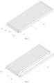
Fig. 1 is a schematic diagram of a liquid cooling system according to an embodiment of the present application; -
Fig. 2 is an exploded view of the liquid cooling system according to the embodiment of the present application; -
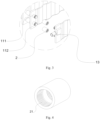
Fig. 3 is an enlarged view at area A inFig. 2 ; -
Fig. 4 is a schematic diagram of a connecting tube of the liquid cooling system according to the embodiment of the present application; and -
Fig. 5 is an application diagram of the liquid cooling system according to the embodiment of the present application. - The meanings of the attached markings are as follows:
1 liquid cooling plate, 11 end seat, 111 inlet port tube, 112 outlet port tube, 12 heat dissipation part, 13 inlet main port, 14 outlet main port, 2 connecting tube, 21 internal thread, 3 battery. - According to
Figs. 1 to 5 , provided in an embodiment of the present application is a liquid cooling system, including:
a plurality ofliquid cooling plates 1 arranged in sequence, in which each of the plurality ofliquid cooling plates 1 includes anend seat 11 and aheat dissipation part 12, and theend seat 11 is provided with both aninlet port tube 111 and anoutlet port tube 112 which are in communication with theheat dissipation part 12; and a plurality of connectingtubes 2, configured to be connected to adjacentinlet port tubes 111 and adjacentoutlet port tubes 112, enabling the plurality ofliquid cooling plates 1 to be connected in parallel. An inletmain port 13 and an outletmain port 14 are respectively provided on twooutermost end seats 11,the inletmain port 13 is configured to be in communication with theinlet port tube 111 to input cooling liquid into theheat dissipation part 12, and the outletmain port 14 is configured to be in communication with theoutlet port tube 112 to discharge the cooling liquid from theheat dissipation part 12. - With the above arrangement, a full parallel connection between the
liquid cooling plates 1 is realized, which not only ensures the reliability of the connection between theliquid cooling plates 1, but also reduces the flow resistance of the liquid cooling system and improves the uniformity of the liquid cooling flow rate, so that the liquid cooling system have a better liquid cooling effect. - According to
Figs. 3 to 4 , specifically, an inner wall of each of the plurality of connectingtubes 2 is provided withinternal threads 21, an outer wall of theinlet port tube 111 is provided with a first external thread, and the plurality of connectingtubes 2 are connected to the adjacentinlet port tubes 111 by engaging theinternal threads 21 with first external threads of the adjacentinlet port tubes 111, thereby strengthening the connection strength between the plurality of connectingtubes 2 and the adjacentinlet port tubes 111, and enhancing the reliability of the connection between the plurality ofliquid cooling plates 1. More specifically, theinternal threads 21 are respectively provided on two ends of the inner wall of each of the plurality of connectingtubes 2, and accordingly, the first external thread is provided on an end of the outer wall of theinlet port tube 111, so that, under the premise of ensuring the reliability of the connection, threading parts of the each of connectingtubes 2 and theinlet port tube 111 are reduced, thereby reducing the cost and time of processing. - In some implementations, an outer wall of the
outlet port tubes 112 is provided with a second external thread, and the plurality of connectingtubes 2 are connected to the adjacentoutlet port tubes 112 by engaging theinternal threads 21 with second external threads of the adjacentoutlet port tubes 112, thereby strengthening the connection strength between theconnecting tubes 2 and theoutlet port tubes 112, and enhancing the reliability of the connection between the plurality ofliquid cooling plates 1. In other implementations, theinternal threads 21 are respectively provided on two ends of the inner wall of each of the plurality of connectingtubes 2, and accordingly, the second external thread is provided on an end of the outer wall of theoutlet port tube 112, so that, under the premise of ensuring the reliability of the connection, threading part of theoutlet port tube 112 is reduced, thereby reducing the cost and time of processing. - In some implementations, a liquid cooling channel in a semi-annular shape is formed inside the
heat dissipation part 12, and two ends of the liquid cooling channel are connected to theinlet port tube 111 and theoutlet port tube 12 respectively, so that the cooling liquid flows fully through the inside of theheat dissipation part 12, thereby providing a better cooling effect for theheat dissipation part 12. In some implementations, the liquid cooling channel is arranged along an extension direction of theheat dissipation part 12. - Since there are tolerances in the production of the cells and the assembly of the liquid cooling system, the plurality of connecting
tubes 2 are provided as a thermally fused tube, and the plurality of connectingtubes 2 are deformable by thermally fusing, so as to be attached with theinlet port tube 111 and/or theoutlet port tube 112. Therefore, the plurality ofliquid cooling plates 1 are attached with thecells 3 between the plurality ofliquid cooling plates 1 completely, which compensates gaps generated by the tolerances, improves the compactness of the overall structure of the liquid cooling system, and realizes effects of ensuring the reliability of the connection of the plurality ofliquid cooling plates 1 and reducing the overall volume of the liquid cooling system. In an actual assembly, an inner diameter of each of the plurality of connectingtubes 2 are greater than or equal to an outer diameter of theinlet port tube 111, and is greater than or equal to an outer diameter of theoutlet port tube 112. Firstly, connectingtubes 2 of the plurality of connectingtubes 2 are socketed onto theinlet port tube 111 and theoutlet port tube 112 on one ofadjacent end seats 11, then theinlet port tube 111 and theoutlet port tube 112 on the other of theadjacent end seats 11 are aligned with the aboveinlet port tube 111 and the aboveoutlet port tube 112 socketed the with theconnecting tubes 2, and finally, the connectingtubes 2 are moved to the middle of twoinlet port tubes 111 on theadjacent end seats 11 and the middle of twooutlet port tubes 112 on theadjacent end seats 11, and are thermally fused. Thereby, one of the connectingtubes 2 is thermally fused to the twoinlet port tubes 111, and another of the connectingtubes 2 is thermally fused to the twooutlet port tubes 112. - In some implementations, the plurality of
liquid cooling plates 1 are equally spaced apart from each other, so that mounting spaces for placing cells are formed between the plurality ofliquid cooling plates 1. When thecells 3 are cylindrical cells, a projection of theheat dissipation part 12 in a horizontal plane is wavy, so as to allow a side of theheat dissipation part 12 to be attached with thecells 3, thereby strengthening the compactness of the internal structure of the liquid cooling system, which not only enhances the effect of the cooling, but also reduces the overall volume of the liquid cooling system. - In some implementations, the
inlet port tube 111 is higher than theoutlet port tube 112 in a gravity direction, so as to allow the cooling liquid to flow through theheat dissipation part 12 from top to bottom, which utilizes gravity to reduce the flow resistance of the liquid cooling system, and realizes a better liquid cooling effect. - The following is an exemplary description of a working procedure of the above liquid cooling system of the embodiment:
- The cooling liquid flows sequentially into each
inlet port tube 111 through the inletmain port 13, flows through the interior of theheat dissipation part 12 along the liquid cooling channel under the effect of gravity, and then flows to the outletmain port 14 through eachoutlet port tube 112 to be discharged, thereby completing cooling for one time. In actual use, the above process is repeated to cool thecells 3 for multiple times. - Based on the same concept, further disclosed in the present application a battery case, which is applied with a liquid cooling system as described above.
- It should be noted that the various embodiments in the present specification are described in a progressive manner. Each embodiment focuses on the differences with other embodiments. It is sufficient to refer to each embodiment for the same and similar parts.
Claims (10)
- A liquid cooling system, comprising:a plurality of liquid cooling plates (1) arranged in sequence, wherein each of the plurality of liquid cooling plates (1) comprises an end seat (11) and a heat dissipation part (12), and the end seat (11) is provided with both an inlet port tube (111) and an outlet port tube (112) which are in communication with the heat dissipation part (12); anda plurality of connecting tubes (2), configured to be connected to adjacent inlet port tubes (111) and adjacent outlet port tubes (112), enabling the plurality of liquid cooling plates (1) to be connected in parallel,wherein an inlet main port (13) and an outlet main port (14) are respectively provided on two outermost end seats (11), the inlet main port (13) is configured to be in communication with the inlet port tube (111) to input cooling liquid into the heat dissipation part (12), and the outlet main port (14) is configured to be in communication with the outlet port tubes (112) to discharge the cooling liquid from the heat dissipation part (12).
- The liquid cooling system according to claim 1, wherein an inner wall of each of the plurality of connecting tubes (2) is provided with internal threads (21), an outer wall of the inlet port tube (111) is provided with a first external thread, and the plurality of connecting tubes (2) are connected to the adjacent inlet port tubes (111) by engaging the internal threads (21) with the first external threads of the adjacent inlet port tubes (111).
- The liquid cooling system according to claim 2, wherein the internal threads (21) are provided on two ends of the inner wall of each of the plurality of connecting tubes (2), and/or, the first external thread is provided on an end of the outer wall of the inlet port tube (111).
- The liquid cooling system according to claim 2, wherein an outer wall of the outlet port tubes (112) is provided with a second external thread, and the plurality of connecting tubes (2) are connected to the adjacent outlet port tubes (112) by engaging the internal threads (21) with second external threads of the adjacent outlet port tubes (111).
- The liquid cooling system according to claim 4, wherein the internal threads (21) are provided on two ends of the inner wall of each of the plurality of connecting tubes (2), and/or, the second external thread is provided on an end of the outer wall of the inlet port tube (111).
- The liquid cooling system according to any one of claims 1 to 5, wherein a liquid cooling channel in a semi-annular shape is formed inside the heat dissipation part (12), and two ends of the liquid cooling channel are connected to the inlet port tube (111) and the outlet port tube (112) respectively.
- The liquid cooling system according to any one of claims 1 to 5, wherein at least one of the plurality of connecting tubes (2) are provided as a thermally fused tube, and each of the at least one connecting tubes (2) is deformable by thermally fusing, so as to be attached with the inlet port tube (111) and/or the outlet port tube (112).
- The liquid cooling system according to any one of claims 1 to 5, wherein the plurality of liquid cooling plates (1) are equally spaced apart from each other, so that mounting spaces for placing cells are formed between the plurality of liquid cooling plates (1).
- The liquid cooling system according to any one of claims 1 to 5, wherein the inlet port tube (111) is higher than the outlet port tube (112) in a gravity direction, so as to allow the cooling liquid to flow through the heat dissipation part (12) from top to bottom.
- A battery case, applied with the liquid cooling system as claimed in any one of claims 1 to 9.
Applications Claiming Priority (2)
| Application Number | Priority Date | Filing Date | Title |
|---|---|---|---|
| CN202322476717.0U CN220856702U (en) | 2023-09-12 | 2023-09-12 | Liquid cooling system and battery box using the same |
| PCT/CN2024/106979 WO2025055558A1 (en) | 2023-09-12 | 2024-07-23 | Liquid cooling system and battery box using same |
Publications (2)
| Publication Number | Publication Date |
|---|---|
| EP4546508A1 true EP4546508A1 (en) | 2025-04-30 |
| EP4546508A4 EP4546508A4 (en) | 2025-10-29 |
Family
ID=94243308
Family Applications (1)
| Application Number | Title | Priority Date | Filing Date |
|---|---|---|---|
| EP24817459.1A Pending EP4546508A4 (en) | 2023-09-12 | 2024-07-23 | LIQUID COOLING SYSTEM AND BATTERY BOX WITH IT |
Country Status (4)
| Country | Link |
|---|---|
| US (1) | US20250140976A1 (en) |
| EP (1) | EP4546508A4 (en) |
| JP (1) | JP2025532747A (en) |
| KR (1) | KR20250006341A (en) |
Family Cites Families (9)
| Publication number | Priority date | Publication date | Assignee | Title |
|---|---|---|---|---|
| FR2860287B1 (en) * | 2003-09-26 | 2006-10-06 | Valeo Climatisation | HEAT EXCHANGER WITH SEVERAL ROWS OF TUBES |
| CN205752451U (en) * | 2016-06-27 | 2016-11-30 | 华霆(合肥)动力技术有限公司 | A kind of liquid cold flat tube attachment structure |
| CN208507891U (en) * | 2018-08-08 | 2019-02-15 | 天臣新能源有限公司 | A kind of novel cylindrical battery core liquid cooling mould group |
| CN219393516U (en) * | 2022-12-06 | 2023-07-21 | 中创新航科技股份有限公司 | battery pack |
| CN115732802A (en) * | 2022-12-12 | 2023-03-03 | 湖北亿纬动力有限公司 | High-efficiency cooling battery module |
| CN116315267B (en) * | 2023-02-28 | 2026-04-14 | 华为数字能源技术有限公司 | Battery pack and energy storage system |
| CN219457896U (en) * | 2023-04-13 | 2023-08-01 | 惠州亿纬锂能股份有限公司 | Cell module |
| CN219626816U (en) * | 2023-04-13 | 2023-09-01 | 惠州亿纬锂能股份有限公司 | Cell module |
| CN116365102A (en) * | 2023-04-27 | 2023-06-30 | 惠州亿纬锂能股份有限公司 | A liquid cooling system and battery pack |
-
2024
- 2024-07-23 KR KR1020247042885A patent/KR20250006341A/en active Pending
- 2024-07-23 EP EP24817459.1A patent/EP4546508A4/en active Pending
- 2024-07-23 JP JP2024575846A patent/JP2025532747A/en active Pending
-
2025
- 2025-01-06 US US19/011,568 patent/US20250140976A1/en active Pending
Also Published As
| Publication number | Publication date |
|---|---|
| KR20250006341A (en) | 2025-01-10 |
| JP2025532747A (en) | 2025-10-03 |
| US20250140976A1 (en) | 2025-05-01 |
| EP4546508A4 (en) | 2025-10-29 |
Similar Documents
| Publication | Publication Date | Title |
|---|---|---|
| CN108847509B (en) | Cooling structure and battery module | |
| US8835038B2 (en) | Battery cell cooler | |
| US9499068B2 (en) | Battery pack | |
| JP2020510965A (en) | Cooling jacket with non-uniform flow path for cooling battery cell surface and battery module including the same | |
| CN110690525B (en) | Chute interactive necking channel liquid cooling plate | |
| CN110890605B (en) | Double-side cross-section tapered liquid cooling plate capable of working in double faces | |
| CN110838607A (en) | A type of liquid-cooled plate with tapered section | |
| CN114050347A (en) | A cylindrical battery module | |
| WO2024178992A1 (en) | Battery pack and energy storage system | |
| EP4535510A1 (en) | Battery pack and vehicle comprising same | |
| EP4546508A1 (en) | Liquid cooling system and battery box using same | |
| CN107623101B (en) | Power battery cooling device and battery module | |
| CN110854466A (en) | A spaced interactive microchannel liquid cooling plate | |
| CN220856702U (en) | Liquid cooling system and battery box using the same | |
| CN216529034U (en) | Liquid cooling battery device, power battery and electrical equipment | |
| CN221057521U (en) | Multi-surface liquid cooling module structure and battery | |
| CN218513537U (en) | Cooling plate, cooling device and battery module | |
| CN218919042U (en) | Battery heat exchanger, battery pack, thermal management system and vehicle | |
| CN218548566U (en) | Water cooling plate assembly, water cooling system and battery pack | |
| WO2024087017A1 (en) | Liquid cooling plate for pouch battery, and battery module | |
| CN218602557U (en) | Battery pack | |
| CN218586077U (en) | Side cooling module for battery | |
| CN222463072U (en) | Battery, battery module and electric equipment | |
| CN219917313U (en) | Liquid cooling plate and battery system | |
| CN220774508U (en) | Cooling device and power battery |
Legal Events
| Date | Code | Title | Description |
|---|---|---|---|
| STAA | Information on the status of an ep patent application or granted ep patent |
Free format text: STATUS: UNKNOWN |
|
| STAA | Information on the status of an ep patent application or granted ep patent |
Free format text: STATUS: THE INTERNATIONAL PUBLICATION HAS BEEN MADE |
|
| PUAI | Public reference made under article 153(3) epc to a published international application that has entered the european phase |
Free format text: ORIGINAL CODE: 0009012 |
|
| STAA | Information on the status of an ep patent application or granted ep patent |
Free format text: STATUS: REQUEST FOR EXAMINATION WAS MADE |
|
| 17P | Request for examination filed |
Effective date: 20241212 |
|
| AK | Designated contracting states |
Kind code of ref document: A1 Designated state(s): AL AT BE BG CH CY CZ DE DK EE ES FI FR GB GR HR HU IE IS IT LI LT LU LV MC ME MK MT NL NO PL PT RO RS SE SI SK SM TR |
|
| A4 | Supplementary search report drawn up and despatched |
Effective date: 20250929 |
|
| RIC1 | Information provided on ipc code assigned before grant |
Ipc: H01M 10/643 20140101AFI20250923BHEP Ipc: H01M 10/6557 20140101ALI20250923BHEP Ipc: H01M 10/6568 20140101ALI20250923BHEP Ipc: H01M 10/625 20140101ALI20250923BHEP Ipc: H01M 10/613 20140101ALI20250923BHEP Ipc: F28F 1/02 20060101ALI20250923BHEP Ipc: F28F 9/02 20060101ALI20250923BHEP |