EP4546507A1 - Apparatus for containing thermal events of energy storage devices - Google Patents
Apparatus for containing thermal events of energy storage devices Download PDFInfo
- Publication number
- EP4546507A1 EP4546507A1 EP24188090.5A EP24188090A EP4546507A1 EP 4546507 A1 EP4546507 A1 EP 4546507A1 EP 24188090 A EP24188090 A EP 24188090A EP 4546507 A1 EP4546507 A1 EP 4546507A1
- Authority
- EP
- European Patent Office
- Prior art keywords
- filter
- battery
- energy storage
- pathway
- outlet
- Prior art date
- Legal status (The legal status is an assumption and is not a legal conclusion. Google has not performed a legal analysis and makes no representation as to the accuracy of the status listed.)
- Pending
Links
Images


Classifications
-
- H—ELECTRICITY
- H01—ELECTRIC ELEMENTS
- H01M—PROCESSES OR MEANS, e.g. BATTERIES, FOR THE DIRECT CONVERSION OF CHEMICAL ENERGY INTO ELECTRICAL ENERGY
- H01M50/00—Constructional details or processes of manufacture of the non-active parts of electrochemical cells other than fuel cells, e.g. hybrid cells
- H01M50/20—Mountings; Secondary casings or frames; Racks, modules or packs; Suspension devices; Shock absorbers; Transport or carrying devices; Holders
- H01M50/244—Secondary casings; Racks; Suspension devices; Carrying devices; Holders characterised by their mounting method
-
- H—ELECTRICITY
- H01—ELECTRIC ELEMENTS
- H01M—PROCESSES OR MEANS, e.g. BATTERIES, FOR THE DIRECT CONVERSION OF CHEMICAL ENERGY INTO ELECTRICAL ENERGY
- H01M10/00—Secondary cells; Manufacture thereof
- H01M10/60—Heating or cooling; Temperature control
- H01M10/65—Means for temperature control structurally associated with the cells
- H01M10/655—Solid structures for heat exchange or heat conduction
- H01M10/6556—Solid parts with flow channel passages or pipes for heat exchange
-
- B—PERFORMING OPERATIONS; TRANSPORTING
- B01—PHYSICAL OR CHEMICAL PROCESSES OR APPARATUS IN GENERAL
- B01D—SEPARATION
- B01D39/00—Filtering material for liquid or gaseous fluids
- B01D39/14—Other self-supporting filtering material ; Other filtering material
- B01D39/20—Other self-supporting filtering material ; Other filtering material of inorganic material, e.g. asbestos paper, metallic filtering material of non-woven wires
- B01D39/2027—Metallic material
- B01D39/2031—Metallic material the material being particulate
- B01D39/2034—Metallic material the material being particulate sintered or bonded by inorganic agents
-
- B—PERFORMING OPERATIONS; TRANSPORTING
- B60—VEHICLES IN GENERAL
- B60L—PROPULSION OF ELECTRICALLY-PROPELLED VEHICLES; SUPPLYING ELECTRIC POWER FOR AUXILIARY EQUIPMENT OF ELECTRICALLY-PROPELLED VEHICLES; ELECTRODYNAMIC BRAKE SYSTEMS FOR VEHICLES IN GENERAL; MAGNETIC SUSPENSION OR LEVITATION FOR VEHICLES; MONITORING OPERATING VARIABLES OF ELECTRICALLY-PROPELLED VEHICLES; ELECTRIC SAFETY DEVICES FOR ELECTRICALLY-PROPELLED VEHICLES
- B60L3/00—Electric devices on electrically-propelled vehicles for safety purposes; Monitoring operating variables, e.g. speed, deceleration or energy consumption
- B60L3/0023—Detecting, eliminating, remedying or compensating for drive train abnormalities, e.g. failures within the drive train
- B60L3/0046—Detecting, eliminating, remedying or compensating for drive train abnormalities, e.g. failures within the drive train relating to electric energy storage systems, e.g. batteries or capacitors
-
- B—PERFORMING OPERATIONS; TRANSPORTING
- B60—VEHICLES IN GENERAL
- B60L—PROPULSION OF ELECTRICALLY-PROPELLED VEHICLES; SUPPLYING ELECTRIC POWER FOR AUXILIARY EQUIPMENT OF ELECTRICALLY-PROPELLED VEHICLES; ELECTRODYNAMIC BRAKE SYSTEMS FOR VEHICLES IN GENERAL; MAGNETIC SUSPENSION OR LEVITATION FOR VEHICLES; MONITORING OPERATING VARIABLES OF ELECTRICALLY-PROPELLED VEHICLES; ELECTRIC SAFETY DEVICES FOR ELECTRICALLY-PROPELLED VEHICLES
- B60L50/00—Electric propulsion with power supplied within the vehicle
- B60L50/50—Electric propulsion with power supplied within the vehicle using propulsion power supplied by batteries or fuel cells
- B60L50/60—Electric propulsion with power supplied within the vehicle using propulsion power supplied by batteries or fuel cells using power supplied by batteries
- B60L50/64—Constructional details of batteries specially adapted for electric vehicles
-
- H—ELECTRICITY
- H01—ELECTRIC ELEMENTS
- H01M—PROCESSES OR MEANS, e.g. BATTERIES, FOR THE DIRECT CONVERSION OF CHEMICAL ENERGY INTO ELECTRICAL ENERGY
- H01M10/00—Secondary cells; Manufacture thereof
- H01M10/05—Accumulators with non-aqueous electrolyte
- H01M10/052—Li-accumulators
- H01M10/0525—Rocking-chair batteries, i.e. batteries with lithium insertion or intercalation in both electrodes; Lithium-ion batteries
-
- H—ELECTRICITY
- H01—ELECTRIC ELEMENTS
- H01M—PROCESSES OR MEANS, e.g. BATTERIES, FOR THE DIRECT CONVERSION OF CHEMICAL ENERGY INTO ELECTRICAL ENERGY
- H01M10/00—Secondary cells; Manufacture thereof
- H01M10/42—Methods or arrangements for servicing or maintenance of secondary cells or secondary half-cells
- H01M10/52—Removing gases inside the secondary cell, e.g. by absorption
-
- H—ELECTRICITY
- H01—ELECTRIC ELEMENTS
- H01M—PROCESSES OR MEANS, e.g. BATTERIES, FOR THE DIRECT CONVERSION OF CHEMICAL ENERGY INTO ELECTRICAL ENERGY
- H01M10/00—Secondary cells; Manufacture thereof
- H01M10/60—Heating or cooling; Temperature control
- H01M10/61—Types of temperature control
- H01M10/613—Cooling or keeping cold
-
- H—ELECTRICITY
- H01—ELECTRIC ELEMENTS
- H01M—PROCESSES OR MEANS, e.g. BATTERIES, FOR THE DIRECT CONVERSION OF CHEMICAL ENERGY INTO ELECTRICAL ENERGY
- H01M10/00—Secondary cells; Manufacture thereof
- H01M10/60—Heating or cooling; Temperature control
- H01M10/62—Heating or cooling; Temperature control specially adapted for specific applications
- H01M10/625—Vehicles
-
- H—ELECTRICITY
- H01—ELECTRIC ELEMENTS
- H01M—PROCESSES OR MEANS, e.g. BATTERIES, FOR THE DIRECT CONVERSION OF CHEMICAL ENERGY INTO ELECTRICAL ENERGY
- H01M10/00—Secondary cells; Manufacture thereof
- H01M10/60—Heating or cooling; Temperature control
- H01M10/65—Means for temperature control structurally associated with the cells
- H01M10/658—Means for temperature control structurally associated with the cells by thermal insulation or shielding
-
- H—ELECTRICITY
- H01—ELECTRIC ELEMENTS
- H01M—PROCESSES OR MEANS, e.g. BATTERIES, FOR THE DIRECT CONVERSION OF CHEMICAL ENERGY INTO ELECTRICAL ENERGY
- H01M50/00—Constructional details or processes of manufacture of the non-active parts of electrochemical cells other than fuel cells, e.g. hybrid cells
- H01M50/20—Mountings; Secondary casings or frames; Racks, modules or packs; Suspension devices; Shock absorbers; Transport or carrying devices; Holders
- H01M50/202—Casings or frames around the primary casing of a single cell or a single battery
-
- H—ELECTRICITY
- H01—ELECTRIC ELEMENTS
- H01M—PROCESSES OR MEANS, e.g. BATTERIES, FOR THE DIRECT CONVERSION OF CHEMICAL ENERGY INTO ELECTRICAL ENERGY
- H01M50/00—Constructional details or processes of manufacture of the non-active parts of electrochemical cells other than fuel cells, e.g. hybrid cells
- H01M50/20—Mountings; Secondary casings or frames; Racks, modules or packs; Suspension devices; Shock absorbers; Transport or carrying devices; Holders
- H01M50/271—Lids or covers for the racks or secondary casings
-
- H—ELECTRICITY
- H01—ELECTRIC ELEMENTS
- H01M—PROCESSES OR MEANS, e.g. BATTERIES, FOR THE DIRECT CONVERSION OF CHEMICAL ENERGY INTO ELECTRICAL ENERGY
- H01M50/00—Constructional details or processes of manufacture of the non-active parts of electrochemical cells other than fuel cells, e.g. hybrid cells
- H01M50/30—Arrangements for facilitating escape of gases
-
- H—ELECTRICITY
- H01—ELECTRIC ELEMENTS
- H01M—PROCESSES OR MEANS, e.g. BATTERIES, FOR THE DIRECT CONVERSION OF CHEMICAL ENERGY INTO ELECTRICAL ENERGY
- H01M50/00—Constructional details or processes of manufacture of the non-active parts of electrochemical cells other than fuel cells, e.g. hybrid cells
- H01M50/30—Arrangements for facilitating escape of gases
- H01M50/317—Re-sealable arrangements
-
- H—ELECTRICITY
- H01—ELECTRIC ELEMENTS
- H01M—PROCESSES OR MEANS, e.g. BATTERIES, FOR THE DIRECT CONVERSION OF CHEMICAL ENERGY INTO ELECTRICAL ENERGY
- H01M50/00—Constructional details or processes of manufacture of the non-active parts of electrochemical cells other than fuel cells, e.g. hybrid cells
- H01M50/30—Arrangements for facilitating escape of gases
- H01M50/317—Re-sealable arrangements
- H01M50/325—Re-sealable arrangements comprising deformable valve members, e.g. elastic or flexible valve members
-
- H—ELECTRICITY
- H01—ELECTRIC ELEMENTS
- H01M—PROCESSES OR MEANS, e.g. BATTERIES, FOR THE DIRECT CONVERSION OF CHEMICAL ENERGY INTO ELECTRICAL ENERGY
- H01M50/00—Constructional details or processes of manufacture of the non-active parts of electrochemical cells other than fuel cells, e.g. hybrid cells
- H01M50/30—Arrangements for facilitating escape of gases
- H01M50/35—Gas exhaust passages comprising elongated, tortuous or labyrinth-shaped exhaust passages
-
- H—ELECTRICITY
- H01—ELECTRIC ELEMENTS
- H01M—PROCESSES OR MEANS, e.g. BATTERIES, FOR THE DIRECT CONVERSION OF CHEMICAL ENERGY INTO ELECTRICAL ENERGY
- H01M50/00—Constructional details or processes of manufacture of the non-active parts of electrochemical cells other than fuel cells, e.g. hybrid cells
- H01M50/30—Arrangements for facilitating escape of gases
- H01M50/35—Gas exhaust passages comprising elongated, tortuous or labyrinth-shaped exhaust passages
- H01M50/367—Internal gas exhaust passages forming part of the battery cover or case; Double cover vent systems
-
- B—PERFORMING OPERATIONS; TRANSPORTING
- B60—VEHICLES IN GENERAL
- B60L—PROPULSION OF ELECTRICALLY-PROPELLED VEHICLES; SUPPLYING ELECTRIC POWER FOR AUXILIARY EQUIPMENT OF ELECTRICALLY-PROPELLED VEHICLES; ELECTRODYNAMIC BRAKE SYSTEMS FOR VEHICLES IN GENERAL; MAGNETIC SUSPENSION OR LEVITATION FOR VEHICLES; MONITORING OPERATING VARIABLES OF ELECTRICALLY-PROPELLED VEHICLES; ELECTRIC SAFETY DEVICES FOR ELECTRICALLY-PROPELLED VEHICLES
- B60L2240/00—Control parameters of input or output; Target parameters
- B60L2240/10—Vehicle control parameters
- B60L2240/36—Temperature of vehicle components or parts
-
- B—PERFORMING OPERATIONS; TRANSPORTING
- B60—VEHICLES IN GENERAL
- B60L—PROPULSION OF ELECTRICALLY-PROPELLED VEHICLES; SUPPLYING ELECTRIC POWER FOR AUXILIARY EQUIPMENT OF ELECTRICALLY-PROPELLED VEHICLES; ELECTRODYNAMIC BRAKE SYSTEMS FOR VEHICLES IN GENERAL; MAGNETIC SUSPENSION OR LEVITATION FOR VEHICLES; MONITORING OPERATING VARIABLES OF ELECTRICALLY-PROPELLED VEHICLES; ELECTRIC SAFETY DEVICES FOR ELECTRICALLY-PROPELLED VEHICLES
- B60L2240/00—Control parameters of input or output; Target parameters
- B60L2240/40—Drive Train control parameters
- B60L2240/54—Drive Train control parameters related to batteries
- B60L2240/545—Temperature
-
- H—ELECTRICITY
- H01—ELECTRIC ELEMENTS
- H01M—PROCESSES OR MEANS, e.g. BATTERIES, FOR THE DIRECT CONVERSION OF CHEMICAL ENERGY INTO ELECTRICAL ENERGY
- H01M2200/00—Safety devices for primary or secondary batteries
- H01M2200/20—Pressure-sensitive devices
-
- H—ELECTRICITY
- H01—ELECTRIC ELEMENTS
- H01M—PROCESSES OR MEANS, e.g. BATTERIES, FOR THE DIRECT CONVERSION OF CHEMICAL ENERGY INTO ELECTRICAL ENERGY
- H01M2220/00—Batteries for particular applications
- H01M2220/20—Batteries in motive systems, e.g. vehicle, ship, plane
-
- Y—GENERAL TAGGING OF NEW TECHNOLOGICAL DEVELOPMENTS; GENERAL TAGGING OF CROSS-SECTIONAL TECHNOLOGIES SPANNING OVER SEVERAL SECTIONS OF THE IPC; TECHNICAL SUBJECTS COVERED BY FORMER USPC CROSS-REFERENCE ART COLLECTIONS [XRACs] AND DIGESTS
- Y02—TECHNOLOGIES OR APPLICATIONS FOR MITIGATION OR ADAPTATION AGAINST CLIMATE CHANGE
- Y02E—REDUCTION OF GREENHOUSE GAS [GHG] EMISSIONS, RELATED TO ENERGY GENERATION, TRANSMISSION OR DISTRIBUTION
- Y02E60/00—Enabling technologies; Technologies with a potential or indirect contribution to GHG emissions mitigation
- Y02E60/10—Energy storage using batteries
Definitions
- the present disclosure relates generally to safety apparatus for energy storage devices and, more particularly, to apparatus for containing thermal events of energy storage devices, such as batteries.
- a thermal runaway event may occur when the temperature of the battery surges rapidly outside of a normal operating temperature range, thereby causing a sudden release of the energy stored in the battery.
- gases and battery byproducts e.g., material/debris
- gases and battery byproducts may be rapidly discharged or expelled from the battery into the surrounding environment.
- the gases and material mix with the surrounding air, the mixture may spontaneously combust and potentially cause a fire.
- a thermal runaway event of a battery may cause damage to structures near the battery.
- a thermal runaway event may cause damage to the interior of vehicle, possibly impacting the operation of vehicle.
- batteries e.g., lithium ion batteries
- the gel packs may be wrapped around a battery to absorb heat generated from the battery and to reduce the possibility of a thermal runaway event.
- the use of gel packs may suffer from many shortcomings. For example, the battery may still fail and release gases and byproducts from the battery into the environment. The gases and byproducts may mix with moisture in the surrounding air, which may generate flammable gas.
- thermal runaway events may occur if a gel pack fails to cover a sufficient surface area of a battery.
- gel packs may only be able to provide partial direct surface coverage of a battery which can severely limit the ability to resolve temperature spikes in the battery. Thus, the surface area coverage shortcomings associated with the use of gel packs may limit the effectiveness of such an approach to address thermal runaway events.
- the present application is directed to apparatus for improving the safety of the use of energy storage devices and sources.
- the apparatus can mitigate and/or reduce adverse effects caused by thermal events of energy storage devices.
- the apparatus may be configured to contain and suppress the gases and byproducts (e.g., battery debris and materials) expelled or released during a thermal runaway event of an energy storage device, such as a lithium-ion battery.
- the apparatus may also minimize potential damage to internal electrical components/elements and structures near the energy storage device.
- the apparatus enables the energy storage device to be located in unpressurized regions of aircraft,
- the apparatus may be configured to be mounted or attached to a housing containing one or more energy storage devices (e.g., batteries).
- an apparatus for containing thermal events of at least one energy storage device may comprise a containment enclosure including a venting chamber having a pathway.
- the pathway may be configured to enable emissions discharged from the at least one energy storage device to be directed from an inlet portion to an outlet portion.
- the outlet portion of the pathway may include an outlet aperture.
- the apparatus may also comprises a filter having an input end and output end. The input end of the filter may be configured to filter the emissions passing through the outlet aperture of the pathway.
- the apparatus may also comprise a valve coupled to the output end of the filter. The valve may be configured to open at a predetermined threshold pressure level to release emissions into an atmosphereis provided.
- a battery module in another aspect, may comprise a housing and a battery disposed in the housing.
- An enclosure may be mounted to the housing for containing thermal runway events.
- the enclosure may include a venting chamber having a pathway.
- An inlet aperture may be configured to enable emissions discharged from the battery to enter into the pathway and an outlet aperture may be configured to enable the emissions to exit the pathway.
- a filter may be configured to filter the emissions passing through the outlet aperture and a valve may be configured to open at a predetermined threshold pressure level to release at least a portion of the emissions into an atmosphere.
- the distinguishing letter "A" may be used.
- the reference number 264 may be used without a distinguishing letter.
- an ordinal term e.g., "first,” “second,” “third,” etc.
- an element such as a structure, a component, an operation, etc.
- the term “set” refers to a grouping of one or more elements
- the term “plurality” refers to multiple elements.
- the present application is directed to apparatus for improving the safety of the use of energy storage devices or sources.
- the apparatus can mitigate and/or reduce adverse effects caused by thermal events of energy storage devices.
- the apparatus may be configured to contain and suppress gases and/or byproducts (e.g., battery debris and material) discharged or released during a thermal runaway event of an energy storage device, such as a battery.
- gases and/or byproducts e.g., battery debris and material
- the apparatus may also prevent or minimize any potential damage to internal electrical component/elements and structures near the energy storage device.
- the apparatus enables the energy storage device to be located in unpressurized regions of aircraft.
- the apparatus may be configured to be attached or coupled to a housing containing one or more energy storage devices (e.g., batteries).
- FIG. 1 an example embodiment of an aircraft 100 is illustrated in which an apparatus for containing thermal events of an energy storage device (e.g., a battery) can be implemented.
- the aircraft 100 of Figure 1 includes a fuselage 102 having a left side 104, a right side 106, a nose end 108 and a tail end 110.
- a first wing 112 is coupled to the left side 104 of the fuselage 102.
- a second wing 114 is coupled to the right side 106 of the fuselage 102.
- the aircraft 100 includes a door 116 disposed on the left side 104 of the fuselage 102.
- Passengers and/or crew may enter (e.g., board) and/or exit (e.g., disembark) the aircraft 100 via the door 116.
- the aircraft 100 of Figure 1 is merely an example and, thus, other aircrafts may be used without departing from the scope of this disclosure.
- FIG 2 illustrates an energy storage module or assembly 200, according to an exemplary embodiment.
- Figure 3 shown an exploded perspective view of the energy storage module 200.
- the energy storage module 200 can house an energy source or storage device 202 (e.g., a battery and/or battery pack) for supplying electrical power to electrical components and/or systems.
- the energy storage module 200 may house a plurality of energy storage devices.
- the energy storage device 202 may include a rechargeable battery, an electrochemical battery, a lithium-ion battery, a lithium polymer battery, a lead-acid battery, a nickel cadmium battery, a nickel metal hydride battery, or any other suitable energy device.
- the energy storage module 200 may be designed to withstand high temperatures and internal pressures produced by thermal events of the energy storage device 202.
- the energy storage module 200 may be incorporated or employed within a vehicle or structure.
- the energy storage module 200 may be disposed within the fuselage of the aircraft 100 of Figure 1 .
- the energy storage module 200 may be incorporated into a train, spacecraft, a building, or any other type of vehicle or structure.
- the energy storage module 200 may include a housing or base portion 204 and a containment enclosure or cover portion 206.
- the containment enclosure 206 of the energy storage module 200 may be configured to be mounted or attached to the housing 204.
- the housing 204 of the energy storage module 200 may be configured to support and hold the energy storage device 202.
- the housing 204 may be designed to withstand adverse effects (e.g., high temperatures and/or internal pressures) caused by thermal events (e.g., thermal runaway events) of the energy storage device 202.
- the housing 204 may be formed from various materials or combinations of materials.
- the housing 204 may be formed from a heat resistant material, such as metal.
- the housing 204 may be constructed of stainless steel, titanium, and/or aluminum.
- the containment enclosure 206 of the energy storage module 200 may be constructed of other types of materials.
- the housing 204 of the energy storage module 200 may be generally rectangular or square shaped.
- the housing 204 may include a bottom 210, sidewalls 212, and end walls 214.
- the housing 204 may include a first sidewall 220, a second sidewall 222 that is opposite to the first sidewall 220, a first end wall 224 that is coupled between the first sidewall 220 and the second sidewall 222, and a second end wall 226 that is coupled between the first sidewall 220 and the second sidewall 222 and which is opposite to the first end wall 224.
- the housing 204 of the energy storage module 200 can have other shapes and/or include any suitable number of side/end walls.
- the bottom 210, sidewalls 212, end walls 214 of the housing 204 may define a compartment or cavity 230 having a sufficient size and shape to accept and hold the energy storage device 202.
- insulation may be placed around the energy storage device 202 and/or between the energy storage device 202 and the housing 204.
- the compartment 230 of the housing 204 may house a battery pack or battery 231.
- the battery pack 231 may include one or more battery arrays. Each of the battery arrays may include a plurality of battery cells. The battery cells may be stacked side-by-side and retained relative to one another. In some embodiments, the battery cells may be lithium-ion battery cells.
- the battery cells can be implemented as other types of battery cells, such lithium polymer cells, nickel cadmium cells, nickel-metal hydride, or any other rechargeable battery cell or material.
- the housing 204 of the energy storage module 200 is depicted as containing one battery, any number of batteries or battery packs may be disposed in the compartment 230 of the housing 204.
- the compartment 230 of the housing 204 may also house other electric components or elements 232.
- an electrical circuit board 234 and/or electrical components may be disposed in the compartment 230 of the housing 204.
- the housing 204 may include additional compartments to hold other batteries and/or electrical components.
- the electric components 232 disposed in the compartment 230 of the housing 204 may be communicatively coupled to external electrical components.
- the second end wall 226 of the housing 204 may have an interface portion 236 having one or more ports and terminals to enable electrical connections to be made between internal and external electrical components.
- the containment enclosure 206 of the energy storage module 200 may be coupled or mounted to the housing 204.
- the containment enclosure 206 may be designed to mitigate adverse effects caused by thermal events of the energy storage device 202 disposed in the compartment 230 of the housing 204.
- the containment enclosure 206 may be configured to contain and suppress gases and/or byproducts (e.g., battery debris and material) expelled or released during a thermal runaway event of the energy storage device 202 (e.g., a lithium-ion battery).
- the containment enclosure 206 enables the energy storage device 202 to be located in unpressurized regions of aircraft.
- the containment enclosure 206 may allow the energy storage device 202 may be located in unoccupied areas of aircraft that may not have firefighting capabilities.
- the containment enclosure 206 may be air-tight and water-tight allowing the containment enclosure 206 to be located in areas exposed to water, moisture, and/or rain.
- the containment enclosure 206 of the energy storage module 200 may be generally rectangular or square shaped. In other examples, the containment enclosure 206 may have other shapes and/or configurations.
- the containment enclosure 206 of the energy storage module 200 may be formed from various materials or combinations of materials.
- the containment enclosure 206 may be formed from a heat resistant material, such as metal.
- the containment enclosure 206 may be constructed of stainless steel, titanium, and/or aluminum. In other examples, the containment enclosure 206 may be constructed of other types of materials.
- the containment enclosure 206 of the energy storage module 200 may be detachably coupled to the housing 204.
- the containment enclosure 206 may be removable from the housing 204 to provide a user with access to the energy storage device 202 (e.g., a battery or battery pack) disposed in the compartment 230 of the housing 204.
- a user may replace and/or remove the energy storage device 202 from the housing 204 of the energy storage module 200.
- the containment enclosure 206 may be attached to the housing 204 by one or more fasteners 238.
- the containment enclosure 206 may be attached to the housing 204 by four fasteners.
- the containment enclosure 206 may engage the periphery of the housing 204 to enclose the compartment 230 of the housing 204.
- an air-tight seal may be formed between the containment enclosure 206 and the housing 204 to prevent the gases and byproducts discharged by the energy storage device 202 from being released into the environment.
- a gap or space may be formed between the energy storage device and the containment enclosure 206 for receiving and collecting gases and/or byproducts discharged from the energy storage device 202.
- a gasket 240 may be used to form a seal between the containment enclosure 206 and the housing 204 of the energy storage module 200.
- the gasket 240 may be generally rectangular or square shaped and may be an O-ring made from a pliable or compressible material, such as rubber, silicone, and plastic polymers.
- the gasket 240 may be seated or disposed in a gasket channel 241 formed around the periphery of the housing 204. Similarly, the gasket 240 may also be seated or disposed in a gasket channel formed around the periphery of the containment enclosure 206.
- the containment enclosure 206 of the energy storage module 200 may include side walls 242, end walls 244, a top 246, a bottom 248, and a venting chamber 250 (e.g., a labyrinth system).
- the venting chamber 250 provide a space or volume to allow gas to expand therein.
- the containment enclosure 206 of the energy storage module 200 may include a first sidewall 252, a second sidewall 254 that is opposite to the first sidewall 252, a first end wall 256 that is coupled between the first sidewall 252 and the second sidewall 254, and a second end wall 258 that is coupled between the first sidewall 252 and the second sidewall 254 and which is opposite to the first end wall 256.
- the containment enclosure 206 of the energy storage module 200 can have other shapes and/or may include any suitable number of side and end walls.
- the containment enclosure 206 may also have a cavity or chamber 261 to accommodate electrical components or elements.
- the venting chamber 250 of the containment enclosure 206 may be formed between the side walls 242, the end walls 244, the top 246, and the bottom 248.
- the venting chamber 250 may be configured to receive and contain gases and byproducts (e.g., battery debris and/or material) discharged or released from the energy storage device 202 (e.g., a battery) during a thermal event.
- gases and byproducts e.g., battery debris and/or material
- the energy storage device 202 may expel gases and byproducts into the compartment 230 of the housing 204, increasing the pressure within the compartment 230.
- the venting chamber 250 may allow the gases and/or byproducts to vent or exit from the compartment 230 of the housing 204 and into the venting chamber 250 of the containment enclosure 206 during the thermal event of the energy storage device 202.
- the venting chamber 250 of the containment enclosure 206 may include a venting path or channel 260 (e.g., a labyrinth passage or path) for carrying the gases and/or byproducts released from the energy storage device 202.
- the venting path 260 may facilitate the cooling and expansion of the gases and/or byproducts released from the energy storage device 202 by extending and directing the discharge of the gases and/or byproducts along the venting path 260.
- the venting path 260 can direct gases away from the energy storage device 202 (e.g., a battery) and other electrical components and elements of the energy storage module 200. As such, the venting path 260 may prevent or mitigate damage to the energy storage device 202 and other electrical components disposed in the housing 204 of the energy storage module 200 during a thermal event of the energy storage device 202.
- the venting path 260 of the venting chamber 250 may be formed between one or more inlet ports or openings 262 (one being shown) and one or more outlet ports or openings 264 (two being shown).
- the venting path 260 may enable gases and byproducts to be directed along the venting path 260 from the one or more inlet ports 262 to the one or more outlet ports 264.
- the one or more inlet ports 262 may be located near or at a first end or inlet portion 266 of the venting path 260 and the one or more outlet ports 264 may be located near or at a second end or outlet portion 268 of the venting path 260.
- the gases and byproducts released by the energy storage device 202 may enter the venting path 260 at the one or more inlet ports 262 and may exit the venting path 260 at the one or more outlet ports 264.
- the venting path 260 of the venting chamber 250 may include one or more C-shaped, U-shaped, or S-shaped sections/portions between the one or more inlet ports 262 and the one or more outlet ports 264.
- the venting chamber 250 can include more than one venting path disposed between the one or more inlet ports 262 and one or more outlet ports 264.
- one or more inlet ports 262 may include an inlet port or opening 262A and the one or more outlet ports 264 may include a first and second outlet ports or openings 264A and 264B.
- the venting path 260 of the venting chamber 250 may be defined between the inlet port 262A and the first and second outlet ports 264A and 264B.
- the venting chamber 250 may include a plurality of inlet ports and one or more outlet ports.
- the inlet port 262A may be formed in and extend through the bottom 248 of the containment enclosure 206 of the energy storage module 200.
- the inlet port 262A may be in communication (e.g., gaseous communication) with the compartment 230 of the housing 204 and the first end 266 of the venting path 260.
- the inlet port 262A may be sized and positioned to allow gases and byproducts to escape from the compartment 230 of the housing 204 and enter into the venting path 260 of the venting chamber 250.
- the inlet port 262A may be cylindrically in shape. In other examples, the inlet port 262A may each have any suitable shape or configuration.
- the bottom 248 of the containment enclosure 206 may include a cover plate or thermal shield plate 270 disposed over the venting chamber 250.
- the cover plate 270 may thermally protect the venting path 260 (e.g., labyrinth passages) to enable expanding gases to cool.
- the inlet port 262A may be defined in the cover plate 270 of the containment enclosure 206. In other embodiments, the inlet port 262A may be defined at any suitable location on the bottom 248 of the containment enclosure 206.
- the cover plate 270 may be detachably coupled to the containment enclosure 206 to enable access to the venting chamber 250.
- the containment enclosure 206 may be attached to the housing 204 by one or more fasteners 272.
- the containment enclosure 206 may be attached to the housing 204 by four fasteners.
- a gasket may be used to form an air-tight seal between the cover plate 270 and the containment enclosure 206.
- the first and second outlet ports 264A and 264B may be in communication with the second end 268 of the venting path 260.
- the first and second outlet ports 264A and 264B may by defined in and extend through the side or end walls of the containment enclosure 206 of the energy storage module 200.
- the first and second outlet ports 264A and 264B may be sized and positioned to allow gases and byproducts to exit the venting path 260 of the venting chamber 250.
- the first and second outlet ports 264A and 264B may be defined in and extend through the first end wall 256 of the containment enclosure 206.
- any of the first and second outlet ports 264A and 264B may be defined and may extend through any other suitable portion (e.g., top, bottom, sidewalls, and end walls) of the containment enclosure 206.
- the first and second outlet ports 264A and 264B may be cylindrical in shape. In other examples, the first and second outlet ports 264A and 264B may have any suitable shape or configuration. In some examples, the first and second outlet ports 264A and 264B may each be configured to accommodate a filter.
- a first filter 274 may be configured to be disposed in the first outlet port 264A and a second filter 276 may be configured to be disposed in the second outlet port 264B.
- the first and second filters 274 and 276 may filter contaminates and particles from the gases and byproducts released from the energy storage device 202.
- the first and second filters 274 and 276 may each comprise a sintered bronze filter or any other suitable filter.
- the first and second filters 274 and 276 may have a shape or configuration corresponding to the shape of the first and second outlet ports 264A and 274B, respectively.
- the first and second filters 274 and 276 may have circular cross-sections.
- a first biasing member 278 may be configured to provide support and maintain the first filter 274 in the first outlet port 264A.
- a second biasing member 280 may be configured to provide support and maintain the second filter 276 in the second outlet port 264B.
- the first and second biasing members 278 and 280 may comprise springs.
- the first and second biasing member 278 and 280 may each be configured to provide a compressive force, when in a compressed state, on the first and second filters 274 and 276 to maintain the filters in the first and second outlet ports 264A and 264B.
- the first and second biasing members 278 and 280 may be compressed and retained against the first and second filters 274 and 276 by an end plate 282.
- the end plate 282 may be attached to containment enclosure 206 by one or more fasteners 284.
- the end plate 282 may be attached to the first end wall 256 of the housing 204 by three fasteners.
- the end plate 282 may have one or more ports or openings 286 extending there-through.
- the end plate 282 includes a first port 286A and a second port 286B.
- the first port 286A of the end plate 282 may be aligned with the first outlet port 264A defined in the first end wall 256 of the containment enclosure 206.
- the second port 286B of the end plate 282 may be aligned with the second outlet port 264B defined in the first end wall 256 of the containment enclosure 206.
- first and second gaskets 288A and 288B may be used to form a seal between the containment enclosure 206 and end plate 282.
- the gaskets 288A and 288B may be generally cylindrical shaped and may be an O-ring made from a pliable or compressible material, such as rubber, silicone, and plastic polymers.
- the first gasket 288A may encircle the first outlet port 264A and the second gasket 288B may encircle the second outlet port 264B.
- the gaskets 288A and 288B may be seated or disposed in a gasket channel in the end plate 282.
- the gaskets 288A and 288B may also be seated or disposed in a gasket channel formed in the first end wall 256 of the containment enclosure 206.
- a first valve 290 is configured to be at least partially disposed in the first port 286A of the end plate 282 and configured to receive gases and byproducts that pass through the first filter 274.
- a second valve 292 is configured to be at least partially disposed in the second port 286B of the end plate 282 and configured to receive gases and byproducts that pass through the second filter 276.
- the first and second valves 290 and 292 may include pressure relief valves. In other examples, the first and second valves 290 and 292 may include a pressure/thermal control valves or any other suitable valves.
- the first and second valves 290 and 292 may be configured to prevent the gases and byproduct discharged from the energy storage device from being released into the atmosphere unless a threshold pressure is reached.
- the threshold pressure may be about 20 PSI.
- the first and second valves 290 and 292 may open to relieve pressure and to release or vent a portion of the gases and byproducts into the atmosphere, which may reduce the likelihood of an eruption of the energy storage module. Therefore, the first and second valves 290 and 292 may release gases during a thermal event, such as a thermal runaway event of a battery, and/or an over-pressurization event.
- instances in this specification where one element is "coupled" to another element can include direct and indirect coupling.
- Direct coupling can be defined as one element coupled to and in some contact with another element.
- Indirect coupling can be defined as coupling between two elements not in direct contact with each other, but having one or more additional elements between the coupled elements.
- securing one element to another element can include direct securing and indirect securing.
- adjacent does not necessarily denote contact. For example, one element can be adjacent another element without being in contact with that element.
- a system, apparatus, structure, article, element, component, or hardware “configured to” perform a specified function is indeed capable of performing the specified function without any alteration, rather than merely having potential to perform the specified function after further modification.
- the system, apparatus, structure, article, element, component, or hardware “configured to” perform a specified function is specifically selected, created, implemented, utilized, programmed, and/or designed for the purpose of performing the specified function.
- "configured to” denotes existing characteristics of a system, apparatus, structure, article, element, component, or hardware which enable the system, apparatus, structure, article, element, component, or hardware to perform the specified function without further modification.
- a system, apparatus, structure, article, element, component, or hardware described as being “configured to” perform a particular function may additionally or alternatively be described as being “adapted to” and/or as being “operative to” perform that function.
- first, second, etc. are used herein merely as labels, and are not intended to impose ordinal, positional, or hierarchical requirements on the items to which these terms refer. Moreover, reference to, e.g., a “second” item does not require or preclude the existence of, e.g., a "first” or lower-numbered item, and/or, e.g., a "third" or higher-numbered item.
Landscapes
- Chemical & Material Sciences (AREA)
- Chemical Kinetics & Catalysis (AREA)
- Electrochemistry (AREA)
- General Chemical & Material Sciences (AREA)
- Engineering & Computer Science (AREA)
- Manufacturing & Machinery (AREA)
- Life Sciences & Earth Sciences (AREA)
- Power Engineering (AREA)
- Sustainable Development (AREA)
- Sustainable Energy (AREA)
- Transportation (AREA)
- Mechanical Engineering (AREA)
- Inorganic Chemistry (AREA)
- Materials Engineering (AREA)
- Geology (AREA)
- Battery Mounting, Suspending (AREA)
- Gas Exhaust Devices For Batteries (AREA)
Abstract
An apparatus for containing thermal events of at least one energy storage device is disclosed. The apparatus may comprise a containment enclosure including a venting chamber having a pathway. The pathway may include an inlet portion and an outlet portion and the pathway may be configured to enable emissions discharged from the at least one energy storage device to be directed from the inlet portion to the outlet portion. The outlet portion of the pathway may include an outlet aperture. A filter may be configured to filter the emissions passing through the outlet aperture of the pathway and a valve may be configured to open at a predetermined threshold pressure level to release at least a portion of the emissions into the atmosphere.
Description
- The present disclosure relates generally to safety apparatus for energy storage devices and, more particularly, to apparatus for containing thermal events of energy storage devices, such as batteries.
- This background description is provided for the purpose of generally presenting the context of the disclosure. Unless otherwise indicated herein, material described in this section is neither expressly nor impliedly admitted to be prior art to the present disclosure or the appended claims.
- Batteries may be used in a variety of applications, such as in vehicles (e.g., automobiles and aircraft) and electronic devices (e.g., computers and mobile telephones). While various types of batteries are available in the marketplace, lithium-ion batteries are commonly used due to their relatively high energy density, lower weight, and lack of battery memory as compared to other types of batteries.
- However, lithium-ion batteries are vulnerable to thermal runaway events. A thermal runaway event may occur when the temperature of the battery surges rapidly outside of a normal operating temperature range, thereby causing a sudden release of the energy stored in the battery. During a thermal runaway event, gases and battery byproducts (e.g., material/debris) may be rapidly discharged or expelled from the battery into the surrounding environment. When the gases and material mix with the surrounding air, the mixture may spontaneously combust and potentially cause a fire. As a result, a thermal runaway event of a battery may cause damage to structures near the battery. For example, when the battery is mounted within a vehicle, such as an aircraft or automobile, a thermal runaway event may cause damage to the interior of vehicle, possibly impacting the operation of vehicle. Thus, the risks associated with the use of batteries (e.g., lithium ion batteries) onboard vehicles should be mitigated.
- Current approaches for addressing thermal runaway events of batteries may rely on the use of gel packs. The gel packs may be wrapped around a battery to absorb heat generated from the battery and to reduce the possibility of a thermal runaway event. The use of gel packs, however, may suffer from many shortcomings. For example, the battery may still fail and release gases and byproducts from the battery into the environment. The gases and byproducts may mix with moisture in the surrounding air, which may generate flammable gas. Additionally, thermal runaway events may occur if a gel pack fails to cover a sufficient surface area of a battery. For example, gel packs may only be able to provide partial direct surface coverage of a battery which can severely limit the ability to resolve temperature spikes in the battery. Thus, the surface area coverage shortcomings associated with the use of gel packs may limit the effectiveness of such an approach to address thermal runaway events.
- For at least these reasons, there remains a need for an apparatus to contain and/or mitigate thermal runaway events of energy storage devices, such as batteries.
- The present application is directed to apparatus for improving the safety of the use of energy storage devices and sources. The apparatus can mitigate and/or reduce adverse effects caused by thermal events of energy storage devices. For example, the apparatus may be configured to contain and suppress the gases and byproducts (e.g., battery debris and materials) expelled or released during a thermal runaway event of an energy storage device, such as a lithium-ion battery. The apparatus may also minimize potential damage to internal electrical components/elements and structures near the energy storage device. Further, the apparatus enables the energy storage device to be located in unpressurized regions of aircraft, The apparatus may be configured to be mounted or attached to a housing containing one or more energy storage devices (e.g., batteries).
- In one aspect, an apparatus for containing thermal events of at least one energy storage device is disclosed. The apparatus may comprise a containment enclosure including a venting chamber having a pathway. The pathway may be configured to enable emissions discharged from the at least one energy storage device to be directed from an inlet portion to an outlet portion. The outlet portion of the pathway may include an outlet aperture. The apparatus may also comprises a filter having an input end and output end. The input end of the filter may be configured to filter the emissions passing through the outlet aperture of the pathway. Further, the apparatus may also comprise a valve coupled to the output end of the filter. The valve may be configured to open at a predetermined threshold pressure level to release emissions into an atmosphereis provided.
- In another aspect, a battery module is disclosed. The battery may comprise a housing and a battery disposed in the housing. An enclosure may be mounted to the housing for containing thermal runway events. The enclosure may include a venting chamber having a pathway. An inlet aperture may be configured to enable emissions discharged from the battery to enter into the pathway and an outlet aperture may be configured to enable the emissions to exit the pathway. A filter may be configured to filter the emissions passing through the outlet aperture and a valve may be configured to open at a predetermined threshold pressure level to release at least a portion of the emissions into an atmosphere.
- The foregoing summary is illustrative only and is not intended to be in any way limiting. In addition to the illustrative aspects, embodiments, and features described above, further aspects, embodiments, and features will become apparent by reference to the figures and the following detailed description.
- A more complete understanding of embodiments of the present application may be derived by referring to the detailed description and claims when considered in conjunction with the following figures, wherein like reference numbers refer to similar elements throughout the figures. The figures are provided to facilitate understanding of the disclosure without limiting the breadth, scope, scale, or applicability of the disclosure. The drawings are not necessarily made to scale.
-
FIG. 1 illustrates an example embodiment of an aircraft in which one or more of the example energy storage modules may be implemented; -
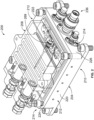
FIG. 2 illustrates a perspective view of an energy storage module, according to an exemplary embodiment; -
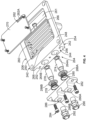
FIG. 3 is an exploded perspective view of the energy storage module ofFigure 2 ; and -
FIG. 4 is a perspective view of a containment enclosure of the energy storage module ofFIG 2 . - The figures and the following description illustrate specific exemplary embodiments. It will be appreciated that those skilled in the art will be able to devise various arrangements that, although not explicitly described or shown herein, embody the principles described herein and are included within the scope of the claims that follow this description. Furthermore, any examples described herein are intended to aid in understanding the principles of the disclosure and are to be construed as being without limitation. As a result, this disclosure is not limited to the specific embodiments or examples described below, but by the claims and their equivalents.
- Particular embodiments are described herein with reference to the drawings. In the description, common features are designated by common reference numbers throughout the drawings. In some drawings, multiple instances of a particular type of feature may be used. Although these features are physically and/or logically distinct, the same reference number is used for each, and the different instances are distinguished by addition of a letter to the reference number. When the features as a group or a type are referred to herein (e.g., when no particular one of the features is being referenced), the reference number is used without a distinguishing letter. However, when one particular feature of multiple features of the same type is referred to herein, the reference number is used with the distinguishing letter. For example, referring to
Figure 4 , outlet ports are illustrated and associated withreference number 264. When referring to a particular one of the outlet ports, such as theoutlet port 264A, the distinguishing letter "A" may be used. However, when referring to any arbitrary one of the outlet ports or to the outlet ports as a group, thereference number 264 may be used without a distinguishing letter. - As used herein, various terminology is used for the purpose of describing particular implementations only and is not intended to be limiting. For example, the singular forms "a," "an," and "the" are intended to include the plural forms as well, unless the context clearly indicates otherwise. Further, the terms "comprise," "comprises," and "comprising" are used interchangeably with "include," "includes," or "including." Additionally, the term "wherein" is used interchangeably with the term "where." As used herein, "exemplary" indicates an example, an implementation, and/or an aspect, and should not be construed as limiting or as indicating a preference or a preferred implementation. As used herein, an ordinal term (e.g., "first," "second," "third," etc.) used to modify an element, such as a structure, a component, an operation, etc., does not by itself indicate any priority or order of the element with respect to another element, but rather merely distinguishes the element from another element having a same name (but for use of the ordinal term). As used herein, the term "set" refers to a grouping of one or more elements, and the term "plurality" refers to multiple elements.
- The present application is directed to apparatus for improving the safety of the use of energy storage devices or sources. The apparatus can mitigate and/or reduce adverse effects caused by thermal events of energy storage devices. For example, the apparatus may be configured to contain and suppress gases and/or byproducts (e.g., battery debris and material) discharged or released during a thermal runaway event of an energy storage device, such as a battery. The apparatus may also prevent or minimize any potential damage to internal electrical component/elements and structures near the energy storage device. Further, the apparatus enables the energy storage device to be located in unpressurized regions of aircraft. The apparatus may be configured to be attached or coupled to a housing containing one or more energy storage devices (e.g., batteries).
- Referring now to the drawings, and more particularly to
Figure 1 , an example embodiment of anaircraft 100 is illustrated in which an apparatus for containing thermal events of an energy storage device (e.g., a battery) can be implemented. Theaircraft 100 ofFigure 1 includes afuselage 102 having aleft side 104, aright side 106, anose end 108 and atail end 110. Afirst wing 112 is coupled to theleft side 104 of thefuselage 102. Asecond wing 114 is coupled to theright side 106 of thefuselage 102. In the illustrated example, theaircraft 100 includes adoor 116 disposed on theleft side 104 of thefuselage 102. Passengers and/or crew may enter (e.g., board) and/or exit (e.g., disembark) theaircraft 100 via thedoor 116. Theaircraft 100 ofFigure 1 is merely an example and, thus, other aircrafts may be used without departing from the scope of this disclosure. -
Figure 2 illustrates an energy storage module orassembly 200, according to an exemplary embodiment.Figure 3 shown an exploded perspective view of theenergy storage module 200. Theenergy storage module 200 can house an energy source or storage device 202 (e.g., a battery and/or battery pack) for supplying electrical power to electrical components and/or systems. In other examples, theenergy storage module 200 may house a plurality of energy storage devices. Theenergy storage device 202 may include a rechargeable battery, an electrochemical battery, a lithium-ion battery, a lithium polymer battery, a lead-acid battery, a nickel cadmium battery, a nickel metal hydride battery, or any other suitable energy device. Theenergy storage module 200 may be designed to withstand high temperatures and internal pressures produced by thermal events of theenergy storage device 202. Theenergy storage module 200 may be incorporated or employed within a vehicle or structure. For example, theenergy storage module 200 may be disposed within the fuselage of theaircraft 100 ofFigure 1 . In other examples, theenergy storage module 200 may be incorporated into a train, spacecraft, a building, or any other type of vehicle or structure. - As shown in
Figures 2 and3 , theenergy storage module 200 may include a housing orbase portion 204 and a containment enclosure orcover portion 206. Thecontainment enclosure 206 of theenergy storage module 200 may be configured to be mounted or attached to thehousing 204. Thehousing 204 of theenergy storage module 200 may be configured to support and hold theenergy storage device 202. Thehousing 204 may be designed to withstand adverse effects (e.g., high temperatures and/or internal pressures) caused by thermal events (e.g., thermal runaway events) of theenergy storage device 202. Thehousing 204 may be formed from various materials or combinations of materials. For example, thehousing 204 may be formed from a heat resistant material, such as metal. In some examples, thehousing 204 may be constructed of stainless steel, titanium, and/or aluminum. In other examples, thecontainment enclosure 206 of theenergy storage module 200 may be constructed of other types of materials. - The
housing 204 of theenergy storage module 200 may be generally rectangular or square shaped. In some embodiments, thehousing 204 may include a bottom 210,sidewalls 212, and endwalls 214. As shown inFigures 2 and3 , thehousing 204 may include afirst sidewall 220, asecond sidewall 222 that is opposite to thefirst sidewall 220, afirst end wall 224 that is coupled between thefirst sidewall 220 and thesecond sidewall 222, and asecond end wall 226 that is coupled between thefirst sidewall 220 and thesecond sidewall 222 and which is opposite to thefirst end wall 224. In other examples, thehousing 204 of theenergy storage module 200 can have other shapes and/or include any suitable number of side/end walls. - The bottom 210,
sidewalls 212, endwalls 214 of thehousing 204 may define a compartment orcavity 230 having a sufficient size and shape to accept and hold theenergy storage device 202. In some examples, insulation may be placed around theenergy storage device 202 and/or between theenergy storage device 202 and thehousing 204. As shown inFigure 2 , thecompartment 230 of thehousing 204 may house a battery pack orbattery 231. Thebattery pack 231 may include one or more battery arrays. Each of the battery arrays may include a plurality of battery cells. The battery cells may be stacked side-by-side and retained relative to one another. In some embodiments, the battery cells may be lithium-ion battery cells. In other examples, the battery cells can be implemented as other types of battery cells, such lithium polymer cells, nickel cadmium cells, nickel-metal hydride, or any other rechargeable battery cell or material. Although thehousing 204 of theenergy storage module 200 is depicted as containing one battery, any number of batteries or battery packs may be disposed in thecompartment 230 of thehousing 204. - The
compartment 230 of thehousing 204 may also house other electric components orelements 232. For example, anelectrical circuit board 234 and/or electrical components may be disposed in thecompartment 230 of thehousing 204. In other examples, thehousing 204 may include additional compartments to hold other batteries and/or electrical components. Theelectric components 232 disposed in thecompartment 230 of thehousing 204 may be communicatively coupled to external electrical components. As shown inFigure 2 , thesecond end wall 226 of thehousing 204 may have aninterface portion 236 having one or more ports and terminals to enable electrical connections to be made between internal and external electrical components. - The
containment enclosure 206 of theenergy storage module 200 may be coupled or mounted to thehousing 204. Thecontainment enclosure 206 may be designed to mitigate adverse effects caused by thermal events of theenergy storage device 202 disposed in thecompartment 230 of thehousing 204. For example, thecontainment enclosure 206 may be configured to contain and suppress gases and/or byproducts (e.g., battery debris and material) expelled or released during a thermal runaway event of the energy storage device 202 (e.g., a lithium-ion battery). Thus, thecontainment enclosure 206 enables theenergy storage device 202 to be located in unpressurized regions of aircraft. For example, thecontainment enclosure 206 may allow theenergy storage device 202 may be located in unoccupied areas of aircraft that may not have firefighting capabilities. Further, thecontainment enclosure 206 may be air-tight and water-tight allowing thecontainment enclosure 206 to be located in areas exposed to water, moisture, and/or rain. - The
containment enclosure 206 of theenergy storage module 200 may be generally rectangular or square shaped. In other examples, thecontainment enclosure 206 may have other shapes and/or configurations. Thecontainment enclosure 206 of theenergy storage module 200 may be formed from various materials or combinations of materials. For example, thecontainment enclosure 206 may be formed from a heat resistant material, such as metal. In some examples, thecontainment enclosure 206 may be constructed of stainless steel, titanium, and/or aluminum. In other examples, thecontainment enclosure 206 may be constructed of other types of materials. - As shown in
Figures 2 and3 , thecontainment enclosure 206 of theenergy storage module 200 may be detachably coupled to thehousing 204. For example, thecontainment enclosure 206 may be removable from thehousing 204 to provide a user with access to the energy storage device 202 (e.g., a battery or battery pack) disposed in thecompartment 230 of thehousing 204. As such, a user may replace and/or remove theenergy storage device 202 from thehousing 204 of theenergy storage module 200. As shown inFigure 3 , thecontainment enclosure 206 may be attached to thehousing 204 by one ormore fasteners 238. For example, thecontainment enclosure 206 may be attached to thehousing 204 by four fasteners. Thecontainment enclosure 206 may engage the periphery of thehousing 204 to enclose thecompartment 230 of thehousing 204. - When the
containment enclosure 206 is attached to thehousing 204 of theenergy storage module 200, an air-tight seal may be formed between thecontainment enclosure 206 and thehousing 204 to prevent the gases and byproducts discharged by theenergy storage device 202 from being released into the environment. A gap or space may be formed between the energy storage device and thecontainment enclosure 206 for receiving and collecting gases and/or byproducts discharged from theenergy storage device 202. As shown inFigure 2 , agasket 240 may be used to form a seal between thecontainment enclosure 206 and thehousing 204 of theenergy storage module 200. Thegasket 240 may be generally rectangular or square shaped and may be an O-ring made from a pliable or compressible material, such as rubber, silicone, and plastic polymers. Thegasket 240 may be seated or disposed in agasket channel 241 formed around the periphery of thehousing 204. Similarly, thegasket 240 may also be seated or disposed in a gasket channel formed around the periphery of thecontainment enclosure 206. - As shown in
Figures 3 and4 , thecontainment enclosure 206 of theenergy storage module 200 may includeside walls 242, endwalls 244, a top 246, a bottom 248, and a venting chamber 250 (e.g., a labyrinth system). The ventingchamber 250 provide a space or volume to allow gas to expand therein. As shown inFigure 2 , thecontainment enclosure 206 of theenergy storage module 200 may include afirst sidewall 252, asecond sidewall 254 that is opposite to thefirst sidewall 252, afirst end wall 256 that is coupled between thefirst sidewall 252 and thesecond sidewall 254, and asecond end wall 258 that is coupled between thefirst sidewall 252 and thesecond sidewall 254 and which is opposite to thefirst end wall 256. In other examples, thecontainment enclosure 206 of theenergy storage module 200 can have other shapes and/or may include any suitable number of side and end walls. In some examples, thecontainment enclosure 206 may also have a cavity orchamber 261 to accommodate electrical components or elements. - The venting
chamber 250 of thecontainment enclosure 206 may be formed between theside walls 242, theend walls 244, the top 246, and the bottom 248. The ventingchamber 250 may be configured to receive and contain gases and byproducts (e.g., battery debris and/or material) discharged or released from the energy storage device 202 (e.g., a battery) during a thermal event. For example, during a thermal runaway event of theenergy storage device 202, theenergy storage device 202 may expel gases and byproducts into thecompartment 230 of thehousing 204, increasing the pressure within thecompartment 230. The ventingchamber 250 may allow the gases and/or byproducts to vent or exit from thecompartment 230 of thehousing 204 and into the ventingchamber 250 of thecontainment enclosure 206 during the thermal event of theenergy storage device 202. - The venting
chamber 250 of thecontainment enclosure 206 may include a venting path or channel 260 (e.g., a labyrinth passage or path) for carrying the gases and/or byproducts released from theenergy storage device 202. The ventingpath 260 may facilitate the cooling and expansion of the gases and/or byproducts released from theenergy storage device 202 by extending and directing the discharge of the gases and/or byproducts along the ventingpath 260. Further, the ventingpath 260 can direct gases away from the energy storage device 202 (e.g., a battery) and other electrical components and elements of theenergy storage module 200. As such, the ventingpath 260 may prevent or mitigate damage to theenergy storage device 202 and other electrical components disposed in thehousing 204 of theenergy storage module 200 during a thermal event of theenergy storage device 202. - As shown in
Figure 2 , the ventingpath 260 of the ventingchamber 250 may be formed between one or more inlet ports or openings 262 (one being shown) and one or more outlet ports or openings 264 (two being shown). The ventingpath 260 may enable gases and byproducts to be directed along the ventingpath 260 from the one ormore inlet ports 262 to the one ormore outlet ports 264. The one ormore inlet ports 262 may be located near or at a first end orinlet portion 266 of the ventingpath 260 and the one ormore outlet ports 264 may be located near or at a second end oroutlet portion 268 of the ventingpath 260. The gases and byproducts released by theenergy storage device 202 may enter theventing path 260 at the one ormore inlet ports 262 and may exit the ventingpath 260 at the one ormore outlet ports 264. In the illustrated example, the ventingpath 260 of the ventingchamber 250 may include one or more C-shaped, U-shaped, or S-shaped sections/portions between the one ormore inlet ports 262 and the one ormore outlet ports 264. In some examples, the ventingchamber 250 can include more than one venting path disposed between the one ormore inlet ports 262 and one ormore outlet ports 264. - As shown in
Figure 2 , one ormore inlet ports 262 may include an inlet port oropening 262A and the one ormore outlet ports 264 may include a first and second outlet ports oropenings path 260 of the ventingchamber 250 may be defined between theinlet port 262A and the first andsecond outlet ports chamber 250 may include a plurality of inlet ports and one or more outlet ports. Theinlet port 262A may be formed in and extend through thebottom 248 of thecontainment enclosure 206 of theenergy storage module 200. Theinlet port 262A may be in communication (e.g., gaseous communication) with thecompartment 230 of thehousing 204 and thefirst end 266 of the ventingpath 260. Theinlet port 262A may be sized and positioned to allow gases and byproducts to escape from thecompartment 230 of thehousing 204 and enter into the ventingpath 260 of the ventingchamber 250. Theinlet port 262A may be cylindrically in shape. In other examples, theinlet port 262A may each have any suitable shape or configuration. Once the gases and byproducts enter theventing path 260 of the ventingchamber 250, the gases may be directed along the ventingpath 260 from theinlet port 262A to the first andsecond outlet ports sensor 269 may be coupled to thecontainment enclosure 206 to measure the temperature and/or pressure in theventing path 260. - As illustrated, the
bottom 248 of thecontainment enclosure 206 may include a cover plate orthermal shield plate 270 disposed over the ventingchamber 250. Thecover plate 270 may thermally protect the venting path 260 (e.g., labyrinth passages) to enable expanding gases to cool. Theinlet port 262A may be defined in thecover plate 270 of thecontainment enclosure 206. In other embodiments, theinlet port 262A may be defined at any suitable location on thebottom 248 of thecontainment enclosure 206. As shown inFigure 2 , thecover plate 270 may be detachably coupled to thecontainment enclosure 206 to enable access to theventing chamber 250. Thecontainment enclosure 206 may be attached to thehousing 204 by one ormore fasteners 272. For example, thecontainment enclosure 206 may be attached to thehousing 204 by four fasteners. In some examples, a gasket may be used to form an air-tight seal between thecover plate 270 and thecontainment enclosure 206. - The first and
second outlet ports second end 268 of the ventingpath 260. The first andsecond outlet ports containment enclosure 206 of theenergy storage module 200. The first andsecond outlet ports path 260 of the ventingchamber 250. As shown inFigure 2 , the first andsecond outlet ports first end wall 256 of thecontainment enclosure 206. In other examples, any of the first andsecond outlet ports containment enclosure 206. The first andsecond outlet ports second outlet ports second outlet ports - As shown in
Figures 3 and4 , afirst filter 274 may be configured to be disposed in thefirst outlet port 264A and asecond filter 276 may be configured to be disposed in thesecond outlet port 264B. The first andsecond filters energy storage device 202. The first andsecond filters second filters second outlet ports 264A and 274B, respectively. For example, the first andsecond filters - A
first biasing member 278 may be configured to provide support and maintain thefirst filter 274 in thefirst outlet port 264A. Asecond biasing member 280 may be configured to provide support and maintain thesecond filter 276 in thesecond outlet port 264B. In some examples, the first andsecond biasing members member second filters second outlet ports second biasing members second filters end plate 282. - The
end plate 282 may be attached tocontainment enclosure 206 by one ormore fasteners 284. For example, theend plate 282 may be attached to thefirst end wall 256 of thehousing 204 by three fasteners. Theend plate 282 may have one or more ports oropenings 286 extending there-through. As shown inFigure 2 , theend plate 282 includes afirst port 286A and asecond port 286B. Thefirst port 286A of theend plate 282 may be aligned with thefirst outlet port 264A defined in thefirst end wall 256 of thecontainment enclosure 206. Similarly, thesecond port 286B of theend plate 282 may be aligned with thesecond outlet port 264B defined in thefirst end wall 256 of thecontainment enclosure 206. - When
end plate 282 is attached to thefirst end wall 256 of thecontainment enclosure 206, an air-tight seal may be formed between thecontainment enclosure 206 and theend plate 282 to prevent the gases and byproducts discharged by theenergy storage device 202 from being released into the environment. As shown inFigure 3 , first andsecond gaskets containment enclosure 206 andend plate 282. Thegaskets first gasket 288A may encircle thefirst outlet port 264A and thesecond gasket 288B may encircle thesecond outlet port 264B. Thegaskets end plate 282. Similarly, thegaskets first end wall 256 of thecontainment enclosure 206. - When the internal pressure in the
venting path 260 of theenergy storage module 200 reaches or exceeds a predetermined level, the gases and byproduct discharged by theenergy storage device 202 may be released into an atmosphere. The atmosphere may be an internal or external atmosphere. As shown inFigure 3 , afirst valve 290 is configured to be at least partially disposed in thefirst port 286A of theend plate 282 and configured to receive gases and byproducts that pass through thefirst filter 274. Similarly, asecond valve 292 is configured to be at least partially disposed in thesecond port 286B of theend plate 282 and configured to receive gases and byproducts that pass through thesecond filter 276. The first andsecond valves second valves - The first and
second valves second valves energy storage module 200 reaches or exceeds a predetermined pressure, the first andsecond valves second valves - The description of the different advantageous arrangements has been presented for purposes of illustration and description, and is not intended to be exhaustive or limited to the examples in the form disclosed. Many modifications and variations will be apparent to those of ordinary skill in the art. Further, different advantageous examples describe different advantages as compared to other advantageous examples. The example or examples selected are chosen and described in order to best explain the principles of the examples, the practical application, and to enable others of ordinary skill in the art to understand the disclosure for various examples with various modifications as are suited to the particular use contemplated.
- Additionally, instances in this specification where one element is "coupled" to another element can include direct and indirect coupling. Direct coupling can be defined as one element coupled to and in some contact with another element. Indirect coupling can be defined as coupling between two elements not in direct contact with each other, but having one or more additional elements between the coupled elements. Further, as used herein, securing one element to another element can include direct securing and indirect securing. Additionally, as used herein, "adjacent" does not necessarily denote contact. For example, one element can be adjacent another element without being in contact with that element.
- As used herein, a system, apparatus, structure, article, element, component, or hardware "configured to" perform a specified function is indeed capable of performing the specified function without any alteration, rather than merely having potential to perform the specified function after further modification. In other words, the system, apparatus, structure, article, element, component, or hardware "configured to" perform a specified function is specifically selected, created, implemented, utilized, programmed, and/or designed for the purpose of performing the specified function. As used herein, "configured to" denotes existing characteristics of a system, apparatus, structure, article, element, component, or hardware which enable the system, apparatus, structure, article, element, component, or hardware to perform the specified function without further modification. For purposes of this disclosure, a system, apparatus, structure, article, element, component, or hardware described as being "configured to" perform a particular function may additionally or alternatively be described as being "adapted to" and/or as being "operative to" perform that function.
- By the term "substantially" and "about" used herein, it is meant that the recited characteristic, parameter, or value need not be achieved exactly, but that deviations or variations, including for example, tolerances, measurement error, measurement accuracy limitations and other factors known to skill in the art, may occur in amounts that do not preclude the effect the characteristic was intended to provide.
- Unless otherwise indicated, the terms "first," "second," etc. are used herein merely as labels, and are not intended to impose ordinal, positional, or hierarchical requirements on the items to which these terms refer. Moreover, reference to, e.g., a "second" item does not require or preclude the existence of, e.g., a "first" or lower-numbered item, and/or, e.g., a "third" or higher-numbered item.
- While apparatus has been described with reference to certain examples, it will be understood by those skilled in the art that various changes can be made and equivalents can be substituted without departing from the scope of the claims. Therefore, it is intended that the present apparatus not be limited to the particular examples disclosed, but that the disclosed apparatus include all embodiments falling within the scope of the appended claims.
- The description incudes the following clauses.
- 1. An apparatus for containing thermal events of at least one energy storage device, the apparatus comprising:
- a containment enclosure including a venting chamber having a pathway, wherein the pathway includes an inlet portion and an outlet portion, wherein the pathway is configured to enable emissions discharged from the at least one energy storage device to be directed from the inlet portion to the outlet portion, and wherein the outlet portion of the pathway includes an outlet aperture;
- a filter having an input end and output end, wherein the input end of the filter is configured to filter the emissions passing through the outlet aperture of the pathway; and
- a valve coupled to the output end of the filter, the valve configured to open at a predetermined threshold pressure level to release emissions into an or the atmosphere.
- 2. The apparatus of clause 1, wherein the filter comprises a first filter, wherein the outlet aperture comprises a first outlet aperture, wherein the valve comprises a first valve, and wherein the outlet portion of the pathway includes a second outlet aperture, and further comprising:
- a second filter having an inlet end and outlet end, wherein the input end of the second filter is configured to filter the emissions passing through the second outlet aperture of the pathway; and
- a second valve coupled to the outlet end of the second filter, the second valve configured to open at the predetermined threshold pressure level to release the emissions into the atmosphere.
- 3. The apparatus of clause 1 or clause 2, wherein the containment enclosure is configured to be mounted to a housing.
- 4. The apparatus of any preceding clause, wherein the at least one energy storage device is disposed in the housing.
- 5. The apparatus of any preceding clause, wherein the containment enclosure includes a thermal shield plate for enclosing at least a portion of the venting chamber.
- 6. The apparatus of clause 5, wherein the thermal shield plate includes at least one opening configured to enable the emissions discharged from the at least one energy storage device to pass through the thermal shield plate and into the inlet portion of the pathway.
- 7. The apparatus of clause 5 or clause 6, wherein the thermal shield plate is spaced from the at least one energy storage device to provide an area for exhausting the emissions discharged from the at least one energy storage device.
- 8. The apparatus of any preceding clause, wherein the at least one energy storage device is selected from at least one rechargeable battery, at least one electrochemical battery, at least one lithium-ion battery, at least one lithium polymer battery, at least one lead-acid battery, at least one nickel cadmium battery, and at least one nickel metal hydride battery.
- 9. The apparatus of any preceding clause, wherein the pathway of the venting chamber comprising a labyrinth passage or path.
- 10. The apparatus of any preceding clause, wherein the pathway of the venting chamber includes one or more C-shaped, U-shaped, or S-shaped portions.
- 11. The apparatus of any preceding clause, wherein the thermal events comprise thermal runaway events.
- 12. The apparatus of any preceding clause, wherein the valve comprises a pressure relief valve.
- 13. The apparatus of any preceding clause, wherein the predetermined threshold pressure level is about 20 psi.
- 14. The apparatus of any preceding clause, wherein the filter comprises a sintered bronze filter.
- 15. The apparatus of any preceding clause, wherein the apparatus is mounted in a vehicle or structure, and wherein the vehicle comprises an aircraft or an automobile.
- 16. A battery module comprising:
- a housing;
- a battery disposed in the housing;
- an enclosure mounted to the housing for containing thermal runway events, wherein the enclosure includes a venting chamber having a pathway, wherein the enclosure includes an inlet aperture and outlet aperture, wherein the inlet aperture is configured to enable emissions discharged from the battery to enter into the pathway, and wherein the outlet aperture is configured to enable the emissions to exit the pathway;
- a filter having an input end and output end, wherein the input end of the filter is configured to filter the emissions passing through the outlet aperture; and
- a valve coupled to the output end of the filter, the valve configured to open at a predetermined threshold pressure level to release at least a portion of the emission into an atmosphere.
- 17. The battery module of clause 16, wherein the filter comprises a first filter, wherein the outlet aperture comprises a first outlet aperture, wherein the valve comprises a first valve, and wherein the enclosure includes a second outlet aperture, and further comprising:
- a second filter having an inlet end and outlet end, wherein the input end of the second filter is configured to filter the emissions passing through the second outlet aperture of the pathway; and
- a second valve coupled to the outlet end of the second filter, the second valve configured to open at the predetermined threshold pressure level to release emissions into the atmosphere.
- 18. The battery module of clause 16 or clause 17, further comprising a thermal shield plate disposed between the battery and the venting chamber, wherein the thermal shield plate includes the inlet aperture.
- 19. The battery module of any of clauses 16 to 18, wherein the valve comprises a pressure relief valve, and wherein the filter comprises a sintered bronze filter.
- 20. The battery module of any of clauses 16 to 19, wherein the battery is selected from one of a rechargeable battery, an electrochemical battery, a lithium-ion battery, a lithium polymer battery, a lead-acid battery, a nickel cadmium battery, and a nickel metal hydride battery.
Claims (15)
- An apparatus for containing thermal events of at least one energy storage device (202), the apparatus comprising:a containment enclosure (206) including a venting chamber (250) having a pathway (260), wherein the pathway includes an inlet portion and an outlet portion, wherein the pathway is configured to enable emissions discharged from the at least one energy storage device to be directed from the inlet portion to the outlet portion, and wherein the outlet portion of the pathway includes an outlet aperture;a filter (274) having an input end and output end, wherein the input end of the filter is configured to filter the emissions passing through the outlet aperture of the pathway; anda valve (290) coupled to the output end of the filter, the valve configured to open at a predetermined threshold pressure level to release emissions into the atmosphere.
- The apparatus of claim 1, wherein the filter comprises a first filter, wherein the outlet aperture comprises a first outlet aperture, wherein the valve comprises a first valve, and wherein the outlet portion of the pathway includes a second outlet aperture, and further comprising:a second filter (276) having an inlet end and outlet end, wherein the input end of the second filter is configured to filter the emissions passing through the second outlet aperture of the pathway; anda second valve (292) coupled to the outlet end of the second filter, the second valve configured to open at the predetermined threshold pressure level to release the emissions into the atmosphere.
- The apparatus of claim 1 or 2, wherein the containment enclosure is configured to be mounted to a housing (204), optionally,
wherein the at least one energy storage device is disposed in the housing. - The apparatus of any preceding claim, wherein the containment enclosure includes a thermal shield plate (270) for enclosing at least a portion of the venting chamber.
- The apparatus of claim 4, wherein the thermal shield plate includes at least one opening configured to enable the emissions discharged from the at least one energy storage device to pass through the thermal shield plate and into the inlet portion of the pathway, and/or,
wherein the thermal shield plate is spaced from the at least one energy storage device to provide an area for exhausting the emissions discharged from the at least one energy storage device. - The apparatus of any preceding claim, wherein the at least one energy storage device is selected from at least one rechargeable battery, at least one electrochemical battery, at least one lithium-ion battery, at least one lithium polymer battery, at least one lead-acid battery, at least one nickel cadmium battery, and at least one nickel metal hydride battery.
- The apparatus of any preceding claim, wherein the pathway of the venting chamber comprising a labyrinth passage or path, and/or,
wherein the pathway of the venting chamber includes one or more C-shaped, U-shaped, or S-shaped portions. - The apparatus of any preceding claim, wherein the thermal events comprise thermal runaway events.
- The apparatus of any preceding claim, wherein the valve comprises a pressure relief valve.
- The apparatus of any preceding claim, wherein the predetermined threshold pressure level is about 20 psi.
- The apparatus of any preceding claim, wherein the filter comprises a sintered bronze filter.
- The apparatus of any preceding claim, wherein the apparatus is mounted in a vehicle or structure, and wherein the vehicle comprises an aircraft or an automobile.
- A battery module comprising:a housing (204);a battery (202) disposed in the housing;an enclosure (206) mounted to the housing for containing thermal runway events, wherein the enclosure includes a venting chamber (250) having a pathway (260), wherein the enclosure includes an inlet aperture and outlet aperture, wherein the inlet aperture is configured to enable emissions discharged from the battery to enter into the pathway, and wherein the outlet aperture is configured to enable the emissions to exit the pathway;a filter (274) having an input end and output end, wherein the input end of the filter is configured to filter the emissions passing through the outlet aperture; anda valve (290) coupled to the output end of the filter, the valve configured to open at a predetermined threshold pressure level to release at least a portion of the emission into the atmosphere.
- The battery module of claim 13, wherein the filter comprises a first filter, wherein the outlet aperture comprises a first outlet aperture, wherein the valve comprises a first valve, and wherein the enclosure includes a second outlet aperture, and further comprising:a second filter (276) having an inlet end and outlet end, wherein the input end of the second filter is configured to filter the emissions passing through the second outlet aperture of the pathway; anda second valve (292) coupled to the outlet end of the second filter, the second valve configured to open at the predetermined threshold pressure level to release emissions into the atmosphere.
- The battery module of claim 13 or claim 14, further comprising a thermal shield plate (270) disposed between the battery and the venting chamber, wherein the thermal shield plate includes the inlet aperture, and/or,wherein the valve comprises a pressure relief valve, and wherein the filter comprises a sintered bronze filter, and/or,wherein the battery is selected from one of a rechargeable battery, an electrochemical battery, a lithium-ion battery, a lithium polymer battery, a lead-acid battery, a nickel cadmium battery, and a nickel metal hydride battery.
Applications Claiming Priority (1)
| Application Number | Priority Date | Filing Date | Title |
|---|---|---|---|
| US18/465,006 US20250087821A1 (en) | 2023-09-11 | 2023-09-11 | Apparatus for Containing Thermal Events of Energy Storage Devices |
Publications (1)
| Publication Number | Publication Date |
|---|---|
| EP4546507A1 true EP4546507A1 (en) | 2025-04-30 |
Family
ID=91924007
Family Applications (1)
| Application Number | Title | Priority Date | Filing Date |
|---|---|---|---|
| EP24188090.5A Pending EP4546507A1 (en) | 2023-09-11 | 2024-07-11 | Apparatus for containing thermal events of energy storage devices |
Country Status (5)
| Country | Link |
|---|---|
| US (1) | US20250087821A1 (en) |
| EP (1) | EP4546507A1 (en) |
| JP (1) | JP2025064956A (en) |
| KR (1) | KR20250038140A (en) |
| CN (1) | CN119601866A (en) |
Citations (5)
| Publication number | Priority date | Publication date | Assignee | Title |
|---|---|---|---|---|
| DE102014208062A1 (en) * | 2014-04-29 | 2015-11-12 | Robert Bosch Gmbh | Battery system with a plurality of battery cells and a degassing device |
| US10529969B2 (en) * | 2016-10-04 | 2020-01-07 | Kabushiki Kaisha Toshiba | Pressure relief mechanism, case, and pressure relief valve |
| DE202020101150U1 (en) * | 2019-11-28 | 2020-03-12 | Elringklinger Ag | Pressure equalization system and electrochemical system |
| DE102020125971A1 (en) * | 2020-10-05 | 2022-04-07 | Bayerische Motoren Werke Aktiengesellschaft | Energy store for a motor vehicle and motor vehicle |
| WO2023069415A1 (en) * | 2021-10-19 | 2023-04-27 | Cadenza Innovation, Inc. | Battery systems with pouch cells |
-
2023
- 2023-09-11 US US18/465,006 patent/US20250087821A1/en active Pending
-
2024
- 2024-07-11 EP EP24188090.5A patent/EP4546507A1/en active Pending
- 2024-08-05 KR KR1020240103569A patent/KR20250038140A/en active Pending
- 2024-09-06 JP JP2024153734A patent/JP2025064956A/en active Pending
- 2024-09-10 CN CN202411264761.8A patent/CN119601866A/en active Pending
Patent Citations (5)
| Publication number | Priority date | Publication date | Assignee | Title |
|---|---|---|---|---|
| DE102014208062A1 (en) * | 2014-04-29 | 2015-11-12 | Robert Bosch Gmbh | Battery system with a plurality of battery cells and a degassing device |
| US10529969B2 (en) * | 2016-10-04 | 2020-01-07 | Kabushiki Kaisha Toshiba | Pressure relief mechanism, case, and pressure relief valve |
| DE202020101150U1 (en) * | 2019-11-28 | 2020-03-12 | Elringklinger Ag | Pressure equalization system and electrochemical system |
| DE102020125971A1 (en) * | 2020-10-05 | 2022-04-07 | Bayerische Motoren Werke Aktiengesellschaft | Energy store for a motor vehicle and motor vehicle |
| WO2023069415A1 (en) * | 2021-10-19 | 2023-04-27 | Cadenza Innovation, Inc. | Battery systems with pouch cells |
Also Published As
| Publication number | Publication date |
|---|---|
| KR20250038140A (en) | 2025-03-19 |
| JP2025064956A (en) | 2025-04-17 |
| US20250087821A1 (en) | 2025-03-13 |
| CN119601866A (en) | 2025-03-11 |
Similar Documents
| Publication | Publication Date | Title |
|---|---|---|
| EP4207462A1 (en) | Battery pack having improved gas venting path | |
| EP3905368B1 (en) | Battery tray and power battery pack | |
| EP3905369A1 (en) | Battery tray and power battery pack | |
| EP3905377A1 (en) | Power battery pack and vehicle | |
| EP4391184A1 (en) | Battery pack having double top cover with venting gas discharge passage180324 | |
| US8100211B2 (en) | Electrochemical accumulator and vehicle comprising an electrochemical accumulator | |
| US20250226502A1 (en) | Battery pack including fire suppression means | |
| EP4379910A1 (en) | Battery pack with improved safety | |
| KR20230062445A (en) | Battery pack with improved safety | |
| US20250087821A1 (en) | Apparatus for Containing Thermal Events of Energy Storage Devices | |
| KR20190013034A (en) | Battery case, battery pack including the same, and vehicle including the same | |
| KR102870479B1 (en) | Battery pack | |
| US11996573B1 (en) | Electrical power storage subsystem | |
| KR102956031B1 (en) | Battery pack with improved safety | |
| CN115663313B (en) | Integrated power distribution system and battery pack | |
| RU2829325C2 (en) | Battery, electric device, method of producing battery and device for producing battery | |
| KR20260039336A (en) | Battery pack | |
| KR20250154779A (en) | Battery module | |
| KR20260067782A (en) | Battery assembly | |
| KR20260051814A (en) | Battery module | |
| KR20260029232A (en) | Battery unit | |
| KR20260067648A (en) | Battery pack | |
| KR20260043320A (en) | Battery pack | |
| KR20250147798A (en) | Battery pack | |
| KR20250154303A (en) | Battery pack |
Legal Events
| Date | Code | Title | Description |
|---|---|---|---|
| PUAI | Public reference made under article 153(3) epc to a published international application that has entered the european phase |
Free format text: ORIGINAL CODE: 0009012 |
|
| STAA | Information on the status of an ep patent application or granted ep patent |
Free format text: STATUS: THE APPLICATION HAS BEEN PUBLISHED |
|
| AK | Designated contracting states |
Kind code of ref document: A1 Designated state(s): AL AT BE BG CH CY CZ DE DK EE ES FI FR GB GR HR HU IE IS IT LI LT LU LV MC ME MK MT NL NO PL PT RO RS SE SI SK SM TR |
|
| STAA | Information on the status of an ep patent application or granted ep patent |
Free format text: STATUS: REQUEST FOR EXAMINATION WAS MADE |
|
| 17P | Request for examination filed |
Effective date: 20250908 |