EP4546478A1 - Rechargeable battery - Google Patents
Rechargeable battery Download PDFInfo
- Publication number
- EP4546478A1 EP4546478A1 EP24191053.8A EP24191053A EP4546478A1 EP 4546478 A1 EP4546478 A1 EP 4546478A1 EP 24191053 A EP24191053 A EP 24191053A EP 4546478 A1 EP4546478 A1 EP 4546478A1
- Authority
- EP
- European Patent Office
- Prior art keywords
- wound part
- wound
- case
- rechargeable battery
- sides
- Prior art date
- Legal status (The legal status is an assumption and is not a legal conclusion. Google has not performed a legal analysis and makes no representation as to the accuracy of the status listed.)
- Pending
Links
Images




Classifications
-
- H—ELECTRICITY
- H01—ELECTRIC ELEMENTS
- H01M—PROCESSES OR MEANS, e.g. BATTERIES, FOR THE DIRECT CONVERSION OF CHEMICAL ENERGY INTO ELECTRICAL ENERGY
- H01M50/00—Constructional details or processes of manufacture of the non-active parts of electrochemical cells other than fuel cells, e.g. hybrid cells
- H01M50/10—Primary casings; Jackets or wrappings
- H01M50/102—Primary casings; Jackets or wrappings characterised by their shape or physical structure
- H01M50/107—Primary casings; Jackets or wrappings characterised by their shape or physical structure having curved cross-section, e.g. round or elliptic
-
- H—ELECTRICITY
- H01—ELECTRIC ELEMENTS
- H01M—PROCESSES OR MEANS, e.g. BATTERIES, FOR THE DIRECT CONVERSION OF CHEMICAL ENERGY INTO ELECTRICAL ENERGY
- H01M10/00—Secondary cells; Manufacture thereof
- H01M10/04—Construction or manufacture in general
- H01M10/0431—Cells with wound or folded electrodes
-
- H—ELECTRICITY
- H01—ELECTRIC ELEMENTS
- H01M—PROCESSES OR MEANS, e.g. BATTERIES, FOR THE DIRECT CONVERSION OF CHEMICAL ENERGY INTO ELECTRICAL ENERGY
- H01M10/00—Secondary cells; Manufacture thereof
- H01M10/05—Accumulators with non-aqueous electrolyte
- H01M10/058—Construction or manufacture
- H01M10/0587—Construction or manufacture of accumulators having only wound construction elements, i.e. wound positive electrodes, wound negative electrodes and wound separators
-
- H—ELECTRICITY
- H01—ELECTRIC ELEMENTS
- H01M—PROCESSES OR MEANS, e.g. BATTERIES, FOR THE DIRECT CONVERSION OF CHEMICAL ENERGY INTO ELECTRICAL ENERGY
- H01M50/00—Constructional details or processes of manufacture of the non-active parts of electrochemical cells other than fuel cells, e.g. hybrid cells
- H01M50/10—Primary casings; Jackets or wrappings
- H01M50/102—Primary casings; Jackets or wrappings characterised by their shape or physical structure
- H01M50/103—Primary casings; Jackets or wrappings characterised by their shape or physical structure prismatic or rectangular
-
- H—ELECTRICITY
- H01—ELECTRIC ELEMENTS
- H01M—PROCESSES OR MEANS, e.g. BATTERIES, FOR THE DIRECT CONVERSION OF CHEMICAL ENERGY INTO ELECTRICAL ENERGY
- H01M50/00—Constructional details or processes of manufacture of the non-active parts of electrochemical cells other than fuel cells, e.g. hybrid cells
- H01M50/10—Primary casings; Jackets or wrappings
- H01M50/147—Lids or covers
- H01M50/148—Lids or covers characterised by their shape
- H01M50/15—Lids or covers characterised by their shape for prismatic or rectangular cells
-
- H—ELECTRICITY
- H01—ELECTRIC ELEMENTS
- H01M—PROCESSES OR MEANS, e.g. BATTERIES, FOR THE DIRECT CONVERSION OF CHEMICAL ENERGY INTO ELECTRICAL ENERGY
- H01M50/00—Constructional details or processes of manufacture of the non-active parts of electrochemical cells other than fuel cells, e.g. hybrid cells
- H01M50/10—Primary casings; Jackets or wrappings
- H01M50/147—Lids or covers
- H01M50/148—Lids or covers characterised by their shape
- H01M50/152—Lids or covers characterised by their shape for cells having curved cross-section, e.g. round or elliptic
-
- H—ELECTRICITY
- H01—ELECTRIC ELEMENTS
- H01M—PROCESSES OR MEANS, e.g. BATTERIES, FOR THE DIRECT CONVERSION OF CHEMICAL ENERGY INTO ELECTRICAL ENERGY
- H01M50/00—Constructional details or processes of manufacture of the non-active parts of electrochemical cells other than fuel cells, e.g. hybrid cells
- H01M50/50—Current conducting connections for cells or batteries
- H01M50/543—Terminals
- H01M50/552—Terminals characterised by their shape
- H01M50/559—Terminals adapted for cells having curved cross-section, e.g. round, elliptic or button cells
-
- H—ELECTRICITY
- H01—ELECTRIC ELEMENTS
- H01M—PROCESSES OR MEANS, e.g. BATTERIES, FOR THE DIRECT CONVERSION OF CHEMICAL ENERGY INTO ELECTRICAL ENERGY
- H01M50/00—Constructional details or processes of manufacture of the non-active parts of electrochemical cells other than fuel cells, e.g. hybrid cells
- H01M50/60—Arrangements or processes for filling or topping-up with liquids; Arrangements or processes for draining liquids from casings
- H01M50/673—Containers for storing liquids; Delivery conduits therefor
- H01M50/682—Containers for storing liquids; Delivery conduits therefor accommodated in battery or cell casings
-
- Y—GENERAL TAGGING OF NEW TECHNOLOGICAL DEVELOPMENTS; GENERAL TAGGING OF CROSS-SECTIONAL TECHNOLOGIES SPANNING OVER SEVERAL SECTIONS OF THE IPC; TECHNICAL SUBJECTS COVERED BY FORMER USPC CROSS-REFERENCE ART COLLECTIONS [XRACs] AND DIGESTS
- Y02—TECHNOLOGIES OR APPLICATIONS FOR MITIGATION OR ADAPTATION AGAINST CLIMATE CHANGE
- Y02E—REDUCTION OF GREENHOUSE GAS [GHG] EMISSIONS, RELATED TO ENERGY GENERATION, TRANSMISSION OR DISTRIBUTION
- Y02E60/00—Enabling technologies; Technologies with a potential or indirect contribution to GHG emissions mitigation
- Y02E60/10—Energy storage using batteries
-
- Y—GENERAL TAGGING OF NEW TECHNOLOGICAL DEVELOPMENTS; GENERAL TAGGING OF CROSS-SECTIONAL TECHNOLOGIES SPANNING OVER SEVERAL SECTIONS OF THE IPC; TECHNICAL SUBJECTS COVERED BY FORMER USPC CROSS-REFERENCE ART COLLECTIONS [XRACs] AND DIGESTS
- Y02—TECHNOLOGIES OR APPLICATIONS FOR MITIGATION OR ADAPTATION AGAINST CLIMATE CHANGE
- Y02P—CLIMATE CHANGE MITIGATION TECHNOLOGIES IN THE PRODUCTION OR PROCESSING OF GOODS
- Y02P70/00—Climate change mitigation technologies in the production process for final industrial or consumer products
- Y02P70/50—Manufacturing or production processes characterised by the final manufactured product
Definitions
- a rechargeable battery is a battery that is repeatedly charged and discharged, unlike a primary battery.
- a small rechargeable battery may be used for portable small electronic devices such as mobile phones, laptop computers, or camcorders.
- a large-capacity and high-density rechargeable battery may be used to store motor driving power or energy of hybrid vehicles and electric vehicles.
- the rechargeable battery may include an electrode assembly for charging and discharging a current, a case for receiving the electrode assembly and an electrolyte solution, a cap plate connected to an opening of the case, and an electrode end for drawing the electrode assembly outside of the cap plate.
- the electrode assembly may be formed as a jelly roll type formed by winding an electrode plate and a separator, or as a stack type formed by stacking an electrode plate and a separator.
- the embodiments may be realized by providing a rechargeable battery including an electrode assembly including a first wound part and a second wound part connected by a connection part, the electrode assembly being wound at each of both ends of a stacked body of a first electrode plate, a first separator, a second electrode plate, and a second separator; and a case that accommodates the electrode assembly, wherein the case includes flat sides facing each other at both sides of the case in a width direction, and curved sides at both ends of the case in a length direction, and the flat sides and the first wound part and the second wound part surround an electrolyte solution accommodating space therebetween.
- connection part may be a part of the stacked body of the first electrode plate, the first separator, the second electrode plate, and the second separator.
- the first wound part and the second wound part may have a circular cylinder shape, and the curved sides of the case may include a first rounded side that faces a side of the first wound part and a second rounded side that faces a side of the second wound part.
- the electrolyte solution accommodating space may be surrounded by a first side of the first wound part and a second side of the second wound part, each of the first wound part and the second wound part having a circular cylinder shape, and the flat sides facing the first side of the first wound part and the second side of the second wound part.
- the first wound part and the second wound part may be wound in the same direction, and the electrolyte solution accommodating space may have a symmetrical structure between the flat sides of the case.
- the first wound part and the second wound part may have a track-shaped pillar shape, and the curved sides of the case may include a 1-1 quarter circle side and a 1-2 quarter circle side that face two sides of the first wound part, and a 2-1 quarter circle side and a 2-2 quarter circle side that face two sides of the second wound part.
- the electrolyte solution accommodating space may be surrounded by a first side of the first wound part and a second side of the second wound part, each of the first wound part and the second wound part having a track-shaped column shape, and the flat sides facing the first side of the first wound part and the second side of the second wound part.
- the case may include a 1-1 flat side, a 1-2 flat side, a 2-1 flat side, and a 2-2 flat side, the first wound part and the second wound part may be wound in the same direction, and the electrolyte solution accommodating space may have a symmetrical structure between the 1-1 flat side and the 1-2 flat side.
- the electrode assembly may further include a third wound part between the first wound part and the second wound part, the third wound part having a circular cylinder shape, the connection part may include a 3-1 connection part connecting the first wound part and the third wound part, and a 3-2 connection part connecting the third wound part and the second wound part, and the curved sides of the case may include a first rounded side that faces a side of the first wound part and a second rounded side that faces the side of the second wound part.
- the electrolyte solution accommodating space may be surrounded by a first side of the first wound part, a third side of the third wound part, a fourth side of the third wound part, and a second side of the second wound part, each of the first wound part, the second wound part, and the third wound part having a circular cylinder shape, and the flat sides facing the first side of the first wound part, the third side of the third wound part, the fourth side of the third wound part, and the second side of the second wound part.
- the first wound part and the second wound part may be wound in the opposite direction, and the third wound part may wind the stacked body in two layers and may be wound in the same direction as the first wound part.
- the electrode assembly may further include a third wound part between the first wound part and the second wound part, the first wound part, the third wound part, and the second wound part may each have a track-shaped column shape, and the curved sides of the case may include a 1-1 quarter circle side and a 1-2 quarter circle side, which respectively face two sides of the first wound part, and a 2-1 quarter circle side and a 2-2 quarter circle side, which respectively face two sides of the second wound part.
- the electrolyte solution accommodating space may be surrounded by a first side of the first wound part, a third side of the third wound part, a fourth side of the third wound part, and a second side of the second wound part, each of the first wound part, the second wound part, and the third wound part having a track-shaped column shape, and the flat sides facing the first side of the first wound part, the third side of the third wound part, the fourth side of the third wound part, and the second side of the second wound part.
- the case may include a 1-1 flat side, a 1-2 flat side, a of 2-1 flat side, and a 2-2 flat side, the first wound part and the second wound part may be wound in the opposite direction, and the third wound part may wind the stacked body in two layers and may be wound in the same direction as the first wound part.
- the rechargeable battery may further include a cap plate that closes and seals an opening of the case, and an electrode terminal connected to a second uncoated region of the second electrode plate and installed in an insulating structure on the cap plate, and wherein the case may be connected to a first uncoated region of the first electrode plate.
- FIG. 1 is a perspective view of a rechargeable battery according to a first embodiment of the present disclosure.
- FIG. 2 is a cross-sectional view taken along a line II-II in FIG. 1 .
- FIG. 3 is an exploded perspective view of a stacked body including a first separator, a first electrode plate, a second separator, and a second electrode plate forming an electrode assembly.
- FIG. 4 is a side view showing a winding direction on a stacked body in FIG. 3 .
- a rechargeable battery 1 of a first embodiment may include an electrode assembly 10 that performs a charge and a discharge, a case 20 accommodating the electrode assembly 10 and an electrolyte solution, a cap plate 30 that closes and seals the opening of the case 20, and an electrode terminal 40 installed with an insulating structure on the cap plate 30.
- FIG. 5 is a side view of an electrode assembly wound in a winding direction of FIG. 4 .
- the electrode assembly 10 may include a first wound part 111 and a second wound part 112 formed by being wound, for example spirally wound, in the same (e.g., clockwise) direction at both ends of the stacked body 11.
- the first wound part 111 and the second wound part 112 may each be formed in a jelly roll state, and may be connected to each other through the connection part 113 to electrically form one electrode assembly 10.
- the connection part 113 may be inclined inside the case 20, for example inclined with respect to the flat sides 21 and 22, respectively.
- the stacked body 11 may be formed by stacking a first separator S1, a first electrode plate E1, a second separator S2, and a second electrode plate E2, and refers to the state before winding with the electrode assembly 10.
- the first electrode plate E1 and the second electrode plate E2 may include coated regions E1a and E2a (in which an active material is coated on both sides of a substrate that is formed of a thin metal plate) and uncoated regions E1b and E2b (in which the substrate is exposed without being coated with the active material).
- the first electrode plate E1 may be a positive electrode formed by coating a positive active material on the substrate made of an aluminum (Al) foil
- the second electrode plate E2 may be a negative electrode formed by coating a negative active material on the substrate made of a copper (Cu) foil.
- the uncoated regions E1b and E2b of the first and second electrode plates E1 and E2 may be at both winding axial ends (upper and lower ends in FIG. 1 and FIG. 2 ) of the electrode assembly 10, respectively.
- the uncoated region E1b of the first electrode plate E1 may be at a first winding axial end
- the uncoated region E2b of the second electrode plate E2 may be at a second winding axial end opposite the first winding axial end.
- the uncoated region E1b of the first electrode plate E1 may be welded to the bottom of case 20.
- the case 20 may accommodate the electrode assembly 10 and the electrolyte solution and may be connected to the first uncoated region E1b of the first electrode plate E1.
- the uncoated region E1b of the first electrode plate E1 may be welded to the current collecting plate, and the current collecting plate may be welded directly to the bottom of the case.
- the uncoated region E2b of the second electrode plate E2 may be welded to the current collecting plate 13, and the current collecting plate 13 may be welded to the electrode terminal 40.
- the electrode terminal 40 may be in a terminal hole H of the cap plate 30 with the gasket 41 therebetween.
- the electrode terminal 40 may be a bolt, and may be fastened with a nut 17 and fixed to the cap plate 30.
- the electrode terminal may be formed as a rivet type.
- the first and second electrode plates may not have an uncoated region at one end of the first and second electrode plates in the width direction, and an uncoated region may be on at least one end of both ends of the first and second electrode plates and the connection part 113 in the length direction, respectively, and a tab may be welded to the uncoated regions to be formed.
- the cap plate 30 may include a vent plate 14 and an electrolyte injection opening 15.
- the vent plate 14 may help prevent explosion of the rechargeable battery 1 by discharging an internal pressure if the internal pressure of the rechargeable battery were to increase and an event were to occur.
- the electrolyte injection opening 15 may be sealed with a stopper 16 after the electrolyte solution is injected.
- FIG. 6 is a cross-sectional view showing a state in which an electrode assembly in FIG. 5 is in a case.
- the case 20 may include a pair of flat surfaces or flat sides 21 and 22 facing each other on (e.g., both) sides of the cap plate 30 in a widthwise direction (i.e., the same as the widthwise direction of the case 20), and a curved surface or curved side (e.g., pair of curved sides) 23 at (e.g., both) ends of the cap plate 30 in the lengthwise direction (i.e., the same as the lengthwise direction of the case 20).
- the case 20 including the flat sides 21 and 22 may establish or include an electrolyte solution accommodating space ES between the first wound part 111 and the second wound part 112.
- the shape of case 20 may be adapted in some areas, e.g, at edges of the case, to the shape of the electrode assembly 10. In this way, the injection and/or amount of electrolyte accommodated in the case 20 may be increased.
- the pair of curved sides 23 may help reduce the entire space or volume of the case 20 that accommodates the electrode assembly 10.
- the pair of flat sides 21 and 22 may help secure or define the electrolyte solution accommodating space ES with the first and second wound parts 111 and 112 therebetween, thereby increasing the amount of the electrolyte solution that may be accommodated in the case 20, even though the entire volume of the case 20 may be reduced.
- connection part 113 may be formed by the stacked body 11 of the first electrode plate E1, the first separator S1, the second electrode plate E2, and the second separator S2.
- the tab may be connected to the connection part 113 by welding.
- first wound part 111 and the second wound part 112 may be formed as, e.g., circular cylinders.
- the curved sides 23 of the case 20 may include a first half circle side or first rounded side 231 that accommodates or faces the (e.g., rounded) side of the first wound part 111 and a second half circle side or second rounded side 232 that accommodates or faces the (e.g., rounded) side of the second wound part 112.
- the curved sides 23 of the case 20 may have a (e.g., concave) rounded shape that is roughly complementary to the (e.g., convex) rounded shape of the first wound part 111 and the second wound part 112.
- the electrolyte solution accommodating space ES may be set or surrounded by or between the first side S11 of the first wound part 111 and the second side S12 of the second wound part 112, which may be formed by a circular cylinder, and the space between the flat sides 21 and 22 facing the first side S11 and the second side S12, thereby increasing the injection and/or accommodation amount of the electrolyte solution.
- the first wound part 111 and the second wound part 112 may be wound in the same (e.g., clockwise) direction, and may help form or provide the electrolyte solution accommodating space ES in or with a symmetrical structure at both sides of the pair of flat sides 21 and 22 in the case 20.
- the symmetrical electrolyte solution accommodating space ES may make the injection amount of the electrolyte solution impregnated on the electrode assembly 10 uniform.
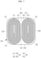
- FIG. 7 is a cross-sectional view of a state in which an electrode assembly is in a case in a rechargeable battery according to a second embodiment of the present disclosure.
- a first wound part 511 and a second wound part 512 may be formed as track-shaped pillars.
- the track-shaped pillar means a three-dimensional shape with rounded edges, e.g. in which a half circle is formed on both left and right sides, and the rounded edges or the half circles on both sides are connected with a straight line to have an oval shape, and has a quadrangle shape when viewed from the front.
- the curved sides 63 of the case 60 may include a 1-1 quarter circle side 311 and a 1-2 quarter circle side 312 that accommodate or face two sides of the first wound part 511, respectively, and a 2-1 quarter circle side 321 and a 2-2 quarter circle side 322 that accommodate or face two sides of the second wound part 512, respectively.
- the quarter circle side refers to a three-dimensional structure in which four corners of a quadrangle are formed as curved or rounded lines when viewed from a flat surface, and has a quadrangle shape when viewed from the front.
- the quarter circle forming the curved line means one piece when the circle is divided into four equal parts by orthogonal diameters.
- the length of the arc in one piece is equivalent to one quarter of the circumference.
- the case 60 may have a prismatic shape, with the base having rounded corners, e.g. in the shape of a quarter circle.
- the sides may also be formed based not on a circle, but on an oval or an ellipse. The sides may then be quarter ellipse sides or quarter oval sides.
- the electrolyte solution accommodating space ES2 may be set by or between the first side S21 of the first wound part 511 and the second side S22 of the second wound part 512, which are formed by the track-shaped pillars, and the space between the flat sides 1511 and 1512 facing the first side S21 and the second side S22, thereby increasing the injection or accommodation amount of the electrolyte solution.
- the case 150 may include a 1-1 flat side 1511 and a 1-2 flat side 1512 and a 2-1 flat side 1521 and a 2-2 flat side 1522.
- the first wound part 511 and the second wound part 512 may be wound in the same (e.g., clockwise) direction, and may form or provide the electrolyte solution accommodating space ES2 in or with a symmetrical structure on the 1-1 flat side 1511 and 1-2 flat side 1512 sides.
- the symmetrical electrolyte solution accommodating space ES2 may help make the amount of the electrolyte solution impregnated on the electrode assembly 50 uniform.
- FIG. 8 is a side view showing a winding direction on a stacked body forming an electrode assembly of a rechargeable battery according to a third embodiment of the present disclosure.
- FIG. 9 is a cross-sectional view of a state in which an electrode assembly of FIG. 8 is in a case.
- an electrode assembly 70 of the rechargeable battery 3 of the third embodiment may further include a third wound part 713 (e.g., a circular cylinder) between a first wound part 111 and a second wound part 112.
- a third wound part 713 e.g., a circular cylinder
- connection part 73 may include a 1-3 connection part 731, which connects the first wound part 111 and the third wound part 713, and a 3-2 connection part 732, which connects the third wound part 713 and the second wound part 112.
- the third wound part 713 may be wound with a pair of mandrel axes 85 on the upper and lower surfaces of the middle position of the stacked body 11.
- the curved sides 83 of the case 80 may include a first rounded side 831 that accommodates or faces the (e.g., rounded) side of the first wound part 111 and a second rounded side 832 that accommodates or faces the (e.g., rounded) side of the second wound part 112.
- the rounded side refers to a three-dimensional structure that has an oval shape in which both opposing sides are formed of the curved lines when viewed from a flat surface and both half circles are connected with a straight line, and has a quadrangle shape when viewed from the front.
- the rounded side that forms the curved line refers to one piece when a circle, oval, or ellipse is divided into two parts by its diameter or major axis. In an implementation, the length of the arc in one piece may be equivalent to 1/2 of the circumference.
- the electrolyte solution accommodating space ES3 may be set by or between the first side S31 of the first wound part 111 and the third side S33 of the third wound part 713, the fourth side S34 of the third wound part 713, the second side S32 of the second wound part 112, and the flat sides 81 and 82 facing the first side S31 and the third side S33 and facing the fourth side S34 and the second side S32, thereby increasing the injection amount of the electrolyte solution.
- the first wound part 111 and the second wound part 112 may be wound in the opposite direction, e.g. clockwise and counter-clockwise, and the third wound part 713 may wind the stacked body 11 in two layers and may be wound in the same direction as the first wound part 111.
- the third wound part 713 may wind the stacked body 11 in two layers by one turn, so the number of turns may be less than that of the first wound part 111 and the second wound part 112.
- the first wound part 111, the second wound part 112, and the third wound part 713 of the third embodiment may form a relatively larger number of the electrolyte solution accommodating spaces ES3 in the case 80, so the injection amount of the electrolyte solution may be further increased.
- FIG. 10 is a cross-sectional view of a state in which an electrode assembly is in a case in a rechargeable battery according to a fourth embodiment of the present disclosure.
- an electrode assembly 90 of a rechargeable battery 4 of the fourth embodiment may further include a third wound part 913 formed as a track-shaped circular cylinder between the first wound part 511 and the second wound part 512.
- the curved sides 63 of the case 100 may include a 1-1 quarter circle side 311 and a 1-2 quarter circle side 312 that respectively accommodate or face two sides of the first wound part 511, and a 2-1 quarter circle side 321 and a 2-2 quarter circle side 322 that respectively accommodate or face two sides of the second wound part 512.
- the electrolyte solution accommodating space ES4 may be set by or between the first side S21 of the first wound part 511 and the third side S23 of the third wound part 913, the fourth side S24 of the third wound part 913 and the second side S22 of the second wound part 512, which may be formed by track-shaped columns, and the space between the flat sides 1011 and 1012 facing the first side S21 and the third side S23 and facing the fourth side S24 and the second side S22, thereby increasing the injection amount of the electrolyte solution.
- the case 100 may include the 1-1 flat side 1011 and the 1-2 flat side 1012, and a 2-1 flat side 1021 and 2-2 flat side 1022.
- the first wound part 511 and the second wound part 512 may be wound in the opposite (e.g., clockwise and counter-clockwise) direction, and may form the electrolyte solution accommodating space ES4 in a symmetrical structure on the 1-1 flat side 1011 and 1-2 flat side 1012 sides.
- the symmetrical electrolyte solution accommodating space ES4 may make the amount of the injected electrolyte solution impregnated on the electrode assembly 90 uniform.
- the first wound part 511 and the second wound part 512 may be wound in the same direction, and the third wound part 913 may wind the stacked body 11 in two layers and may be wound in the same direction as the first wound part 511.
- the third wound part 913 may wind the stacked body 11 in two layers by one turn, so the number of turns may be less than that of the first wound part 511 and the second wound part 512.
- the first wound part 511, the second wound part 512, and the third wound part 913 of the fourth embodiment may form a relatively larger number of electrolyte solution accommodating spaces ES4 within the case 150, so the injection amount of the electrolyte solution may be further increased.
- cylindrical rechargeable batteries may generate excess space due to their circular structure, and due to the internal structure of the case, more than 97% of the space may be occupied by the electrode assembly, making it difficult to secure or accommodate enough electrolyte solution.
- One or more embodiments may provide a rechargeable battery that increases an injection amount of an electrolyte solution.
- One or more embodiments may provide a rechargeable battery that increases an injection amount of an electrolyte solution while reducing the entire space of the case that accommodates the electrode assembly.
- the structure of the case may include the curved surface on both sides to accommodate the electrode assembly with a plurality of wound parts, and the middle part may be connected to the flat surface to accommodate the electrode assembly, so the electrolyte solution accommodating space may be between the plurality of wound parts and the flat surface.
- the electrolyte solution accommodating space may increase the space that substantially accommodates the electrolyte solution while reducing the entire space inside the case, thereby increasing the injection amount of the electrolyte solution. This frees up capacity in the rechargeable battery.
Landscapes
- Chemical & Material Sciences (AREA)
- Chemical Kinetics & Catalysis (AREA)
- Electrochemistry (AREA)
- General Chemical & Material Sciences (AREA)
- Engineering & Computer Science (AREA)
- Manufacturing & Machinery (AREA)
- Secondary Cells (AREA)
Abstract
Description
- Embodiments relate to a rechargeable battery.
- A rechargeable battery is a battery that is repeatedly charged and discharged, unlike a primary battery. A small rechargeable battery may be used for portable small electronic devices such as mobile phones, laptop computers, or camcorders. A large-capacity and high-density rechargeable battery may be used to store motor driving power or energy of hybrid vehicles and electric vehicles.
- The rechargeable battery may include an electrode assembly for charging and discharging a current, a case for receiving the electrode assembly and an electrolyte solution, a cap plate connected to an opening of the case, and an electrode end for drawing the electrode assembly outside of the cap plate. The electrode assembly may be formed as a jelly roll type formed by winding an electrode plate and a separator, or as a stack type formed by stacking an electrode plate and a separator.
- The embodiments may be realized by providing a rechargeable battery including an electrode assembly including a first wound part and a second wound part connected by a connection part, the electrode assembly being wound at each of both ends of a stacked body of a first electrode plate, a first separator, a second electrode plate, and a second separator; and a case that accommodates the electrode assembly, wherein the case includes flat sides facing each other at both sides of the case in a width direction, and curved sides at both ends of the case in a length direction, and the flat sides and the first wound part and the second wound part surround an electrolyte solution accommodating space therebetween.
- The connection part may be a part of the stacked body of the first electrode plate, the first separator, the second electrode plate, and the second separator.
- The first wound part and the second wound part may have a circular cylinder shape, and the curved sides of the case may include a first rounded side that faces a side of the first wound part and a second rounded side that faces a side of the second wound part.
- The electrolyte solution accommodating space may be surrounded by a first side of the first wound part and a second side of the second wound part, each of the first wound part and the second wound part having a circular cylinder shape, and the flat sides facing the first side of the first wound part and the second side of the second wound part.
- The first wound part and the second wound part may be wound in the same direction, and the electrolyte solution accommodating space may have a symmetrical structure between the flat sides of the case.
- The first wound part and the second wound part may have a track-shaped pillar shape, and the curved sides of the case may include a 1-1 quarter circle side and a 1-2 quarter circle side that face two sides of the first wound part, and a 2-1 quarter circle side and a 2-2 quarter circle side that face two sides of the second wound part.
- The electrolyte solution accommodating space may be surrounded by a first side of the first wound part and a second side of the second wound part, each of the first wound part and the second wound part having a track-shaped column shape, and the flat sides facing the first side of the first wound part and the second side of the second wound part.
- The case may include a 1-1 flat side, a 1-2 flat side, a 2-1 flat side, and a 2-2 flat side, the first wound part and the second wound part may be wound in the same direction, and the electrolyte solution accommodating space may have a symmetrical structure between the 1-1 flat side and the 1-2 flat side.
- The electrode assembly may further include a third wound part between the first wound part and the second wound part, the third wound part having a circular cylinder shape, the connection part may include a 3-1 connection part connecting the first wound part and the third wound part, and a 3-2 connection part connecting the third wound part and the second wound part, and the curved sides of the case may include a first rounded side that faces a side of the first wound part and a second rounded side that faces the side of the second wound part.
- The electrolyte solution accommodating space may be surrounded by a first side of the first wound part, a third side of the third wound part, a fourth side of the third wound part, and a second side of the second wound part, each of the first wound part, the second wound part, and the third wound part having a circular cylinder shape, and the flat sides facing the first side of the first wound part, the third side of the third wound part, the fourth side of the third wound part, and the second side of the second wound part.
- The first wound part and the second wound part may be wound in the opposite direction, and the third wound part may wind the stacked body in two layers and may be wound in the same direction as the first wound part.
- The electrode assembly may further include a third wound part between the first wound part and the second wound part, the first wound part, the third wound part, and the second wound part may each have a track-shaped column shape, and the curved sides of the case may include a 1-1 quarter circle side and a 1-2 quarter circle side, which respectively face two sides of the first wound part, and a 2-1 quarter circle side and a 2-2 quarter circle side, which respectively face two sides of the second wound part.
- The electrolyte solution accommodating space may be surrounded by a first side of the first wound part, a third side of the third wound part, a fourth side of the third wound part, and a second side of the second wound part, each of the first wound part, the second wound part, and the third wound part having a track-shaped column shape, and the flat sides facing the first side of the first wound part, the third side of the third wound part, the fourth side of the third wound part, and the second side of the second wound part.
- The case may include a 1-1 flat side, a 1-2 flat side, a of 2-1 flat side, and a 2-2 flat side, the first wound part and the second wound part may be wound in the opposite direction, and the third wound part may wind the stacked body in two layers and may be wound in the same direction as the first wound part.
- The rechargeable battery may further include a cap plate that closes and seals an opening of the case, and an electrode terminal connected to a second uncoated region of the second electrode plate and installed in an insulating structure on the cap plate, and wherein the case may be connected to a first uncoated region of the first electrode plate.
- Features will be apparent to those of skill in the art by describing in detail exemplary embodiments with reference to the attached drawings in which:
-
FIG. 1 is a perspective view of a rechargeable battery according to a first embodiment of the present disclosure. -
FIG. 2 is a cross-sectional view taken along a line II-II inFIG. 1 . -
FIG. 3 is an exploded perspective view of a stacked body including a first separator, a first electrode plate, a second separator, and a second electrode plate forming an electrode assembly. -
FIG. 4 is a side view showing a winding direction on a stacked body inFIG. 3 . -
FIG. 5 is a side view of an electrode assembly wound in a winding direction ofFIG. 4 . -
FIG. 6 is a cross-sectional view of a state in which an electrode assembly ofFIG. 5 is in a case. -
FIG. 7 is a cross-sectional view of a state in which an electrode assembly is in a case in a rechargeable battery according to a second embodiment of the present disclosure. -
FIG. 8 is a side view showing a winding direction on a stacked body forming an electrode assembly of a rechargeable battery according to a third embodiment of the present disclosure. -
FIG. 9 is a cross-sectional view of a state in which an electrode assembly ofFIG. 8 is in a case. -
FIG. 10 is a cross-sectional view of a state in which an electrode assembly is in a case in a rechargeable battery according to a fourth embodiment of the present disclosure. - In the drawing figures, the dimensions of layers and regions may be exaggerated for clarity of illustration. It will also be understood that when a layer or element is referred to as being "on" another layer or element, it can be directly on the other layer or element, or intervening layers may also be present. In addition, it will also be understood that when a layer is referred to as being "between" two layers, it can be the only layer between the two layers, or one or more intervening layers may also be present.
- Hereinafter, the present disclosure will be described more fully with reference to the accompanying drawings, in which embodiments of the disclosure are shown. As those skilled in the art would realize, the described embodiments may be modified in various different ways, all without departing from the scope of the present disclosure. The drawings and description are to be regarded as illustrative in nature and not restrictive. Like reference numerals designate like elements throughout the specification.
-
FIG. 1 is a perspective view of a rechargeable battery according to a first embodiment of the present disclosure.FIG. 2 is a cross-sectional view taken along a line II-II inFIG. 1 .FIG. 3 is an exploded perspective view of a stacked body including a first separator, a first electrode plate, a second separator, and a second electrode plate forming an electrode assembly.FIG. 4 is a side view showing a winding direction on a stacked body inFIG. 3 . - Referring to
FIG. 1 to FIG. 4 , arechargeable battery 1 of a first embodiment may include anelectrode assembly 10 that performs a charge and a discharge, acase 20 accommodating theelectrode assembly 10 and an electrolyte solution, acap plate 30 that closes and seals the opening of thecase 20, and anelectrode terminal 40 installed with an insulating structure on thecap plate 30. -
FIG. 5 is a side view of an electrode assembly wound in a winding direction ofFIG. 4 . Referring toFIG. 1 to FIG. 5 , theelectrode assembly 10 may include afirst wound part 111 and asecond wound part 112 formed by being wound, for example spirally wound, in the same (e.g., clockwise) direction at both ends of thestacked body 11. - In an implementation, the
first wound part 111 may be wound in an upward clockwise direction, and thesecond wound part 112 may be wound in a downward clockwise direction. Thefirst wound part 111 and thesecond wound part 112 may be formed by winding thestacked body 11 by a winding mandrel, and both winding mandrels may move toward each other to narrow the gap between them while performing the winding. - The
first wound part 111 and thesecond wound part 112 may each be formed in a jelly roll state, and may be connected to each other through theconnection part 113 to electrically form oneelectrode assembly 10. Theconnection part 113 may be inclined inside thecase 20, for example inclined with respect to theflat sides - The
stacked body 11 may be formed by stacking a first separator S1, a first electrode plate E1, a second separator S2, and a second electrode plate E2, and refers to the state before winding with theelectrode assembly 10. The first electrode plate E1 and the second electrode plate E2 may include coated regions E1a and E2a (in which an active material is coated on both sides of a substrate that is formed of a thin metal plate) and uncoated regions E1b and E2b (in which the substrate is exposed without being coated with the active material). - In an implementation, the first electrode plate E1 may be a positive electrode formed by coating a positive active material on the substrate made of an aluminum (Al) foil, and the second electrode plate E2 may be a negative electrode formed by coating a negative active material on the substrate made of a copper (Cu) foil.
- The uncoated regions E1b and E2b of the first and second electrode plates E1 and E2 may be at both winding axial ends (upper and lower ends in
FIG. 1 andFIG. 2 ) of theelectrode assembly 10, respectively. For example, the uncoated region E1b of the first electrode plate E1 may be at a first winding axial end, and the uncoated region E2b of the second electrode plate E2 may be at a second winding axial end opposite the first winding axial end. The uncoated region E1b of the first electrode plate E1 may be welded to the bottom ofcase 20. In an implementation, thecase 20 may accommodate theelectrode assembly 10 and the electrolyte solution and may be connected to the first uncoated region E1b of the first electrode plate E1. In an implementation, the uncoated region E1b of the first electrode plate E1 may be welded to the current collecting plate, and the current collecting plate may be welded directly to the bottom of the case. - The uncoated region E2b of the second electrode plate E2 may be welded to the
current collecting plate 13, and thecurrent collecting plate 13 may be welded to theelectrode terminal 40. Theelectrode terminal 40 may be in a terminal hole H of thecap plate 30 with the gasket 41 therebetween. In an implementation, theelectrode terminal 40 may be a bolt, and may be fastened with anut 17 and fixed to thecap plate 30. In an implementation, the electrode terminal may be formed as a rivet type. - In an implementation, the first and second electrode plates may not have an uncoated region at one end of the first and second electrode plates in the width direction, and an uncoated region may be on at least one end of both ends of the first and second electrode plates and the
connection part 113 in the length direction, respectively, and a tab may be welded to the uncoated regions to be formed. - The
cap plate 30 may include avent plate 14 and anelectrolyte injection opening 15. Thevent plate 14 may help prevent explosion of therechargeable battery 1 by discharging an internal pressure if the internal pressure of the rechargeable battery were to increase and an event were to occur. The electrolyte injection opening 15 may be sealed with astopper 16 after the electrolyte solution is injected. -
FIG. 6 is a cross-sectional view showing a state in which an electrode assembly inFIG. 5 is in a case. Referring toFIG. 5 andFIG. 6 , thecase 20 may include a pair of flat surfaces orflat sides cap plate 30 in a widthwise direction (i.e., the same as the widthwise direction of the case 20), and a curved surface or curved side (e.g., pair of curved sides) 23 at (e.g., both) ends of thecap plate 30 in the lengthwise direction (i.e., the same as the lengthwise direction of the case 20). Thecase 20 including theflat sides first wound part 111 and thesecond wound part 112. The shape ofcase 20 may be adapted in some areas, e.g, at edges of the case, to the shape of theelectrode assembly 10. In this way, the injection and/or amount of electrolyte accommodated in thecase 20 may be increased. - The pair of
curved sides 23 may help reduce the entire space or volume of thecase 20 that accommodates theelectrode assembly 10. The pair offlat sides second wound parts case 20, even though the entire volume of thecase 20 may be reduced. - The
connection part 113 may be formed by the stackedbody 11 of the first electrode plate E1, the first separator S1, the second electrode plate E2, and the second separator S2. In an implementation, the tab may be connected to theconnection part 113 by welding. - In an implementation, the
first wound part 111 and thesecond wound part 112 may be formed as, e.g., circular cylinders. Thecurved sides 23 of thecase 20 may include a first half circle side or firstrounded side 231 that accommodates or faces the (e.g., rounded) side of thefirst wound part 111 and a second half circle side or secondrounded side 232 that accommodates or faces the (e.g., rounded) side of thesecond wound part 112. In an implementation, thecurved sides 23 of thecase 20 may have a (e.g., concave) rounded shape that is roughly complementary to the (e.g., convex) rounded shape of thefirst wound part 111 and thesecond wound part 112. - The electrolyte solution accommodating space ES may be set or surrounded by or between the first side S11 of the
first wound part 111 and the second side S12 of thesecond wound part 112, which may be formed by a circular cylinder, and the space between theflat sides - The
first wound part 111 and thesecond wound part 112 may be wound in the same (e.g., clockwise) direction, and may help form or provide the electrolyte solution accommodating space ES in or with a symmetrical structure at both sides of the pair offlat sides case 20. The symmetrical electrolyte solution accommodating space ES may make the injection amount of the electrolyte solution impregnated on theelectrode assembly 10 uniform. - Below, numerous exemplary variations and embodiments of the present disclosure are described. Compared to the first embodiment, repeated descriptions of the same configuration may be omitted, and descriptions of different configurations may be provided.
-
FIG. 7 is a cross-sectional view of a state in which an electrode assembly is in a case in a rechargeable battery according to a second embodiment of the present disclosure. Referring toFIG. 7 , in theelectrode assembly 50 of therechargeable battery 2 of the second embodiment, afirst wound part 511 and asecond wound part 512 may be formed as track-shaped pillars. When viewed from a plan view, the track-shaped pillar means a three-dimensional shape with rounded edges, e.g. in which a half circle is formed on both left and right sides, and the rounded edges or the half circles on both sides are connected with a straight line to have an oval shape, and has a quadrangle shape when viewed from the front. - The
curved sides 63 of the case 60 may include a 1-1quarter circle side 311 and a 1-2quarter circle side 312 that accommodate or face two sides of thefirst wound part 511, respectively, and a 2-1quarter circle side 321 and a 2-2quarter circle side 322 that accommodate or face two sides of thesecond wound part 512, respectively. - The quarter circle side refers to a three-dimensional structure in which four corners of a quadrangle are formed as curved or rounded lines when viewed from a flat surface, and has a quadrangle shape when viewed from the front. The quarter circle forming the curved line means one piece when the circle is divided into four equal parts by orthogonal diameters. The length of the arc in one piece is equivalent to one quarter of the circumference. In other words, the case 60 may have a prismatic shape, with the base having rounded corners, e.g. in the shape of a quarter circle. The sides may also be formed based not on a circle, but on an oval or an ellipse. The sides may then be quarter ellipse sides or quarter oval sides.
- The electrolyte solution accommodating space ES2 may be set by or between the first side S21 of the
first wound part 511 and the second side S22 of thesecond wound part 512, which are formed by the track-shaped pillars, and the space between theflat sides - The
case 150 may include a 1-1flat side 1511 and a 1-2flat side 1512 and a 2-1flat side 1521 and a 2-2flat side 1522. Thefirst wound part 511 and thesecond wound part 512 may be wound in the same (e.g., clockwise) direction, and may form or provide the electrolyte solution accommodating space ES2 in or with a symmetrical structure on the 1-1flat side 1511 and 1-2flat side 1512 sides. The symmetrical electrolyte solution accommodating space ES2 may help make the amount of the electrolyte solution impregnated on theelectrode assembly 50 uniform. -
FIG. 8 is a side view showing a winding direction on a stacked body forming an electrode assembly of a rechargeable battery according to a third embodiment of the present disclosure.FIG. 9 is a cross-sectional view of a state in which an electrode assembly ofFIG. 8 is in a case. Referring toFIG. 8 andFIG. 9 , anelectrode assembly 70 of therechargeable battery 3 of the third embodiment may further include a third wound part 713 (e.g., a circular cylinder) between afirst wound part 111 and asecond wound part 112. - The
connection part 73 may include a 1-3connection part 731, which connects thefirst wound part 111 and thethird wound part 713, and a 3-2connection part 732, which connects thethird wound part 713 and thesecond wound part 112. Thethird wound part 713 may be wound with a pair of mandrel axes 85 on the upper and lower surfaces of the middle position of the stackedbody 11. - The
curved sides 83 of thecase 80 may include a firstrounded side 831 that accommodates or faces the (e.g., rounded) side of thefirst wound part 111 and a secondrounded side 832 that accommodates or faces the (e.g., rounded) side of thesecond wound part 112. - The rounded side refers to a three-dimensional structure that has an oval shape in which both opposing sides are formed of the curved lines when viewed from a flat surface and both half circles are connected with a straight line, and has a quadrangle shape when viewed from the front. The rounded side that forms the curved line refers to one piece when a circle, oval, or ellipse is divided into two parts by its diameter or major axis. In an implementation, the length of the arc in one piece may be equivalent to 1/2 of the circumference.
- The electrolyte solution accommodating space ES3 may be set by or between the first side S31 of the
first wound part 111 and the third side S33 of thethird wound part 713, the fourth side S34 of thethird wound part 713, the second side S32 of thesecond wound part 112, and theflat sides - The
first wound part 111 and thesecond wound part 112 may be wound in the opposite direction, e.g. clockwise and counter-clockwise, and thethird wound part 713 may wind the stackedbody 11 in two layers and may be wound in the same direction as thefirst wound part 111. Thethird wound part 713 may wind the stackedbody 11 in two layers by one turn, so the number of turns may be less than that of thefirst wound part 111 and thesecond wound part 112. - The
first wound part 111, thesecond wound part 112, and thethird wound part 713 of the third embodiment may form a relatively larger number of the electrolyte solution accommodating spaces ES3 in thecase 80, so the injection amount of the electrolyte solution may be further increased. -
FIG. 10 is a cross-sectional view of a state in which an electrode assembly is in a case in a rechargeable battery according to a fourth embodiment of the present disclosure. Referring toFIG. 10 , anelectrode assembly 90 of arechargeable battery 4 of the fourth embodiment may further include athird wound part 913 formed as a track-shaped circular cylinder between thefirst wound part 511 and thesecond wound part 512. - The
curved sides 63 of thecase 100 may include a 1-1quarter circle side 311 and a 1-2quarter circle side 312 that respectively accommodate or face two sides of thefirst wound part 511, and a 2-1quarter circle side 321 and a 2-2quarter circle side 322 that respectively accommodate or face two sides of thesecond wound part 512. - The electrolyte solution accommodating space ES4 may be set by or between the first side S21 of the
first wound part 511 and the third side S23 of thethird wound part 913, the fourth side S24 of thethird wound part 913 and the second side S22 of thesecond wound part 512, which may be formed by track-shaped columns, and the space between theflat sides - The
case 100 may include the 1-1flat side 1011 and the 1-2flat side 1012, and a 2-1flat side 1021 and 2-2flat side 1022. Thefirst wound part 511 and thesecond wound part 512 may be wound in the opposite (e.g., clockwise and counter-clockwise) direction, and may form the electrolyte solution accommodating space ES4 in a symmetrical structure on the 1-1flat side 1011 and 1-2flat side 1012 sides. The symmetrical electrolyte solution accommodating space ES4 may make the amount of the injected electrolyte solution impregnated on theelectrode assembly 90 uniform. - The
first wound part 511 and thesecond wound part 512 may be wound in the same direction, and thethird wound part 913 may wind the stackedbody 11 in two layers and may be wound in the same direction as thefirst wound part 511. Thethird wound part 913 may wind the stackedbody 11 in two layers by one turn, so the number of turns may be less than that of thefirst wound part 511 and thesecond wound part 512. - The
first wound part 511, thesecond wound part 512, and thethird wound part 913 of the fourth embodiment may form a relatively larger number of electrolyte solution accommodating spaces ES4 within thecase 150, so the injection amount of the electrolyte solution may be further increased. - By way of summation and review, cylindrical rechargeable batteries may generate excess space due to their circular structure, and due to the internal structure of the case, more than 97% of the space may be occupied by the electrode assembly, making it difficult to secure or accommodate enough electrolyte solution.
- One or more embodiments may provide a rechargeable battery that increases an injection amount of an electrolyte solution.
- One or more embodiments may provide a rechargeable battery that increases an injection amount of an electrolyte solution while reducing the entire space of the case that accommodates the electrode assembly.
- In the cylindrical rechargeable battery according to an embodiment, the structure of the case may include the curved surface on both sides to accommodate the electrode assembly with a plurality of wound parts, and the middle part may be connected to the flat surface to accommodate the electrode assembly, so the electrolyte solution accommodating space may be between the plurality of wound parts and the flat surface.
- In this way, the electrolyte solution accommodating space may increase the space that substantially accommodates the electrolyte solution while reducing the entire space inside the case, thereby increasing the injection amount of the electrolyte solution. This frees up capacity in the rechargeable battery.
- Example embodiments have been disclosed herein, and although specific terms are employed, they are used and are to be interpreted in a generic and descriptive sense only and not for purposes of limitation. In some instances, as would be apparent to one of ordinary skill in the art as of the filing of the present application, features, characteristics, and/or elements described in connection with a particular embodiment may be used singly or in combination with features, characteristics, and/or elements described in connection with other embodiments unless otherwise specifically indicated. Accordingly, it will be understood by those of skill in the art that various changes in form and details may be made without departing from the scope of the present invention as set forth in the claims.
-
1, 2, 3, 4: rechargeable battery 10, 50: electrode assembly 11: stacked body 14: vent plate 15: electrolyte injection opening 16: cover 17: nut 20, 60: case 21, 22: flat side 23: curved side 30: cap plate 40: electrode terminal 63: curved surface 70: electrode assembly 73: connection part 80: case 81, 82: flat side 83: curved side 85: mandrel axis 90: electrode assembly 100: case 111: first wound part 112: second wound part 113: connection part 150: case 163: curved side 231: first rounded side 232: second rounded side 311: 1-1 quarter circle side 312: 1-2 quarter circle side 321: 2-1 quarter circle side 322: 2-2 quarter circle side 511: first wound part 512: second wound part 713: third wound part 731: 1-3 connection part 732: 3-2 connection part 831: first rounded side 832: second rounded side 913: third wound part 1011, 1511: 1-1 flat side 1012, 1512: 1-2 flat side 1021, 1521: 2-1 flat side 1022, 1522: 2-2 flat side E1: first electrode plate E1a, E2a: coated region E1b, E2b: uncoated region E2: second electrode plate ES, ES2: electrolyte solution accommodating space ES3, ES4: electrolyte solution accommodating space H: terminal hole S1: first separator S2: second separator S11: first side S12, S22: second side S21, S31: first side S23, S33: third side S24, S34: fourth side
Claims (15)
- A rechargeable battery (1, 2, 3, 4), comprising:an electrode assembly (10, 50, 70, 90) including a first wound part (111, 511) and a second wound (112, 512) part connected by a connection part (113, 513), the electrode assembly (10, 50, 70, 90) being wound at each of both ends of a stacked body of a first electrode plate (E1), a first separator (S1), a second electrode plate (E2), and a second separator (S2); anda case (80, 100, 150) that accommodates the electrode assembly (10, 50, 70, 90),wherein:the case (80, 100, 150) includes:flat sides (21, 22) facing each other at both sides of the case (80, 100, 150) in a width direction, andcurved sides (23) at both ends of the case in a length direction, andthe flat sides (21, 22) and the first wound part (111, 511) and the second wound part (112, 512) surround an electrolyte solution accommodating space (ES) therebetween.
- The rechargeable battery (1, 2, 3, 4) of claim 1, wherein the connection part (113, 513) is a part of the stacked body of the first electrode plate (E1), the first separator (S1), the second electrode plate (E2), and the second separator (S2).
- The rechargeable battery (1, 2, 3, 4) of claim 1 or claim 2, wherein:the first wound part (111, 511) and the second wound part (112, 512) have a circular cylinder shape, andthe curved sides (23) of the case (80, 100, 150) include a first rounded side (231) that faces a side of the first wound part (111, 511) and a second rounded side (232) that faces a side of the second wound part (112, 512).
- The rechargeable battery (1, 3) of one of the aforementioned claims, wherein the electrolyte solution accommodating space (ES) is surrounded by:a first side of the first wound part (111, 511) and a second side of the second (112, 512) wound part, each of the first wound part (111, 511) and the second wound part (112, 512) having a circular cylinder shape, andthe flat sides (21, 22) facing the first side of the first wound part (111, 511) and the second side of the second wound part (112, 512).
- The rechargeable battery (1, 2, 3, 4) of one of the aforementioned claims, wherein:the first wound part (111, 511) and the second wound part (112, 512) are wound in the same direction, andthe electrolyte solution accommodating space (ES) has a symmetrical structure between the flat sides (21, 22) of the case (80, 100, 150).
- The rechargeable battery (2, 4) of one of claims 1, 2, or 5, wherein:the first wound part (511) and the second wound part (512) have a track-shaped pillar shape, andthe curved sides of the case (150) include:a 1-1 quarter circle side (311) and a 1-2 quarter circle side (312) that face two sides of the first wound part (511), anda 2-1 quarter circle side (321) and a 2-2 quarter circle side (322) that face two sides of the second wound part (512).
- The rechargeable battery (2, 4) of one of claims 1, 2, 5, or 6, wherein the electrolyte solution accommodating space (ES) is surrounded by:a first side of the first wound part (511) and a second side of the second wound part (512), each of the first wound part (511) and the second wound part (512) having a track-shaped column shape, andthe flat sides (1521, 1522) facing the first side of the first wound part (511) and the second side of the second wound part (512).
- The rechargeable battery (1, 2) of one of the aforementioned claims, wherein:the case (150) includes a 1-1 flat side (1511), a 1-2 flat side (1512), a 2-1 flat side (1521), and a 2-2 flat side (1522),the first wound part (511) and the second wound part (512) are wound in the same direction, andthe electrolyte solution accommodating space (ES) has a symmetrical structure between the 1-1 flat side (1511) and the 1-2 flat side (1512).
- The rechargeable battery (1, 3) of one of claims 1 through 4, wherein:the electrode assembly (70) further includes a third wound (713) part between the first wound part (111) and the second wound part (112), the third wound (713) part having a circular cylinder shape,the connection part (73) includes:a 3-1 connection part (731) connecting the first wound part (111) and the third wound part (713), anda 3-2 connection part (732) connecting the third wound part (713) and the second wound part (112), andthe curved sides of the case (80) include a first rounded side (831) that faces a side of the first wound part (111) and a second rounded (832) side that faces the side of the second wound part (112).
- The rechargeable battery (1, 3) of claim 9, wherein the electrolyte solution accommodating space (ES) is surrounded by:a first side of the first wound part (111), a third side of the third wound part (713), a fourth side of the third wound part (713), and a second side of the second wound part (112), each of the first wound part (111), the second wound part (112), and the third wound part (713) having a circular cylinder shape, andthe flat sides (81, 82) facing the first side of the first wound part (111), the third side of the third wound part (713), the fourth side of the third wound part (713), and the second side of the second wound part (112).
- The rechargeable battery (1, 3) of claim 10, wherein:the first wound part (111) and the second wound part (112) are wound in the opposite direction, andthe third wound part (713) winds the stacked body in two layers and is wound in the same direction as the first wound part (111).
- The rechargeable battery (2, 4) of one of claims 1, 6, 7, or 8, wherein:the electrode assembly (90) further includes a third wound part (913) between the first wound part (511) and the second wound part (512),the first wound part (511), the third wound part (913), and the second wound part (512) each have a track-shaped column shape, andthe curved sides of the case include:a 1-1 quarter circle side (311) and a 1-2 quarter circle side (312), which respectively face two sides of the first wound part (511), anda 2-1 quarter circle side (321) and a 2-2 quarter circle side (322), which respectively face two sides of the second wound part (512).
- The rechargeable battery (2, 4) of claim 12, wherein the electrolyte solution accommodating space (ES) is surrounded by:a first side of the first wound part (511), a third side of the third wound part (913), a fourth side of the third wound part (913), and a second side of the second wound part (512), each of the first wound part (511), the second wound part (512), and the third wound part (913) having a track-shaped column shape, andthe flat sides facing the first side of the first wound part (511), the third side of the third wound part (913), the fourth side of the third wound part (913), and the second side of the second wound part (512).
- The rechargeable battery (2, 4) of claim 12 or claim 13, wherein:the case includes a 1-1 flat side (1011), a 1-2 flat side (1012), a of 2-1 flat side (1021), and a 2-2 flat side (1022),the first wound part (511) and the second wound (512) part are wound in the opposite direction, andthe third wound part (913) winds the stacked body in two layers and is wound in the same direction as the first wound part (511).
- The rechargeable battery (1, 2, 3, 4) of one of the aforementioned claims, further comprising:a cap plate (30) that closes and seals an opening of the case (80, 100, 150), andan electrode terminal (40) connected to a second uncoated region of the second electrode plate (E2) and installed in an insulating structure on the cap plate (30), andwherein the case (80, 100, 150) is connected to a first uncoated region of the first electrode plate (E1).
Applications Claiming Priority (1)
| Application Number | Priority Date | Filing Date | Title |
|---|---|---|---|
| KR1020230143995A KR20250059915A (en) | 2023-10-25 | 2023-10-25 | Rechargeable battery |
Publications (1)
| Publication Number | Publication Date |
|---|---|
| EP4546478A1 true EP4546478A1 (en) | 2025-04-30 |
Family
ID=92106750
Family Applications (1)
| Application Number | Title | Priority Date | Filing Date |
|---|---|---|---|
| EP24191053.8A Pending EP4546478A1 (en) | 2023-10-25 | 2024-07-26 | Rechargeable battery |
Country Status (4)
| Country | Link |
|---|---|
| US (1) | US20250140891A1 (en) |
| EP (1) | EP4546478A1 (en) |
| KR (1) | KR20250059915A (en) |
| CN (1) | CN119890386A (en) |
Citations (4)
| Publication number | Priority date | Publication date | Assignee | Title |
|---|---|---|---|---|
| US20090305121A1 (en) * | 2006-05-15 | 2009-12-10 | Lg Chem, Ltd. | Double winding-typed electrode assembly |
| US10050300B2 (en) * | 2013-03-11 | 2018-08-14 | Google Technology Holdings LLC | Electrochemical cell with multi-faceted geometry |
| US20190006698A1 (en) * | 2016-03-28 | 2019-01-03 | Murata Manufacturing Co., Ltd. | Power storage device and manufacturing method thereof |
| US20230246247A1 (en) * | 2020-09-28 | 2023-08-03 | Ningde Amperex Technology Limited | Battery |
-
2023
- 2023-10-25 KR KR1020230143995A patent/KR20250059915A/en active Pending
-
2024
- 2024-04-12 US US18/633,612 patent/US20250140891A1/en active Pending
- 2024-07-26 EP EP24191053.8A patent/EP4546478A1/en active Pending
- 2024-08-12 CN CN202411098303.1A patent/CN119890386A/en active Pending
Patent Citations (4)
| Publication number | Priority date | Publication date | Assignee | Title |
|---|---|---|---|---|
| US20090305121A1 (en) * | 2006-05-15 | 2009-12-10 | Lg Chem, Ltd. | Double winding-typed electrode assembly |
| US10050300B2 (en) * | 2013-03-11 | 2018-08-14 | Google Technology Holdings LLC | Electrochemical cell with multi-faceted geometry |
| US20190006698A1 (en) * | 2016-03-28 | 2019-01-03 | Murata Manufacturing Co., Ltd. | Power storage device and manufacturing method thereof |
| US20230246247A1 (en) * | 2020-09-28 | 2023-08-03 | Ningde Amperex Technology Limited | Battery |
Also Published As
| Publication number | Publication date |
|---|---|
| CN119890386A (en) | 2025-04-25 |
| KR20250059915A (en) | 2025-05-07 |
| US20250140891A1 (en) | 2025-05-01 |
Similar Documents
| Publication | Publication Date | Title |
|---|---|---|
| KR101147237B1 (en) | Electrode assembly and rechargeable battery including the same | |
| US20250070191A1 (en) | Current collecting member and secondary battery | |
| US9786893B2 (en) | Flexible electrochemical device including electrically connected electrode assemblies | |
| US8815437B2 (en) | Rechargeable battery | |
| US10056577B2 (en) | Battery cell of novel structure | |
| US9876213B2 (en) | Electrode assembly and secondary battery having the electrode assembly | |
| US20190013506A1 (en) | Battery cell having dual welding structures | |
| EP3598531A1 (en) | Flexible battery having reinforcement tab coupling structure and electrode lead bending coupling structure | |
| US9147869B2 (en) | Rechargeable battery | |
| US10593986B2 (en) | Rechargeable battery | |
| US20160218386A1 (en) | Rechargeable battery | |
| KR102618844B1 (en) | Lead tabs for battery terminals | |
| US9263761B2 (en) | Electrode assembly and rechargeable battery having the same | |
| US9153801B2 (en) | Rechargeable battery having a plate terminal and a bolt terminal | |
| EP3211688A1 (en) | Rechargeable battery | |
| US8524384B2 (en) | Rechargeable battery | |
| KR102086036B1 (en) | Battery Cell Comprising Cylindrical Can Having Screw-typed Fastening Portion | |
| US20110135995A1 (en) | Stack type electrode assembly and lithium ion secondary battery having the same | |
| EP4583237A1 (en) | Electrode assembly and secondary battery comprising same | |
| US20250140891A1 (en) | Rechargeable battery | |
| US20260088466A1 (en) | Secondary battery | |
| US20250316745A1 (en) | Secondary battery | |
| EP4604277A1 (en) | Secondary battery and method of manufacturing a secondary battery | |
| US20260106285A1 (en) | Secondary battery and electronic device including secondary battery | |
| US20260045606A1 (en) | Cap assembly and secondary battery including same |
Legal Events
| Date | Code | Title | Description |
|---|---|---|---|
| PUAI | Public reference made under article 153(3) epc to a published international application that has entered the european phase |
Free format text: ORIGINAL CODE: 0009012 |
|
| STAA | Information on the status of an ep patent application or granted ep patent |
Free format text: STATUS: REQUEST FOR EXAMINATION WAS MADE |
|
| 17P | Request for examination filed |
Effective date: 20240726 |
|
| AK | Designated contracting states |
Kind code of ref document: A1 Designated state(s): AL AT BE BG CH CY CZ DE DK EE ES FI FR GB GR HR HU IE IS IT LI LT LU LV MC ME MK MT NL NO PL PT RO RS SE SI SK SM TR |
|
| GRAP | Despatch of communication of intention to grant a patent |
Free format text: ORIGINAL CODE: EPIDOSNIGR1 |
|
| STAA | Information on the status of an ep patent application or granted ep patent |
Free format text: STATUS: GRANT OF PATENT IS INTENDED |
|
| INTG | Intention to grant announced |
Effective date: 20251215 |
|
| RIC1 | Information provided on ipc code assigned before grant |
Ipc: H01M 10/04 20060101AFI20251205BHEP |