EP4546314A1 - Tiled display device - Google Patents
Tiled display device Download PDFInfo
- Publication number
- EP4546314A1 EP4546314A1 EP22741145.1A EP22741145A EP4546314A1 EP 4546314 A1 EP4546314 A1 EP 4546314A1 EP 22741145 A EP22741145 A EP 22741145A EP 4546314 A1 EP4546314 A1 EP 4546314A1
- Authority
- EP
- European Patent Office
- Prior art keywords
- display
- splicing
- disposed
- vacuum suction
- display device
- Prior art date
- Legal status (The legal status is an assumption and is not a legal conclusion. Google has not performed a legal analysis and makes no representation as to the accuracy of the status listed.)
- Pending
Links
Images

Classifications
-
- G—PHYSICS
- G09—EDUCATION; CRYPTOGRAPHY; DISPLAY; ADVERTISING; SEALS
- G09F—DISPLAYING; ADVERTISING; SIGNS; LABELS OR NAME-PLATES; SEALS
- G09F9/00—Indicating arrangements for variable information in which the information is built-up on a support by selection or combination of individual elements
- G09F9/30—Indicating arrangements for variable information in which the information is built-up on a support by selection or combination of individual elements in which the desired character or characters are formed by combining individual elements
- G09F9/302—Indicating arrangements for variable information in which the information is built-up on a support by selection or combination of individual elements in which the desired character or characters are formed by combining individual elements characterised by the form or geometrical disposition of the individual elements
- G09F9/3026—Video wall, i.e. stackable semiconductor matrix display modules
-
- G—PHYSICS
- G02—OPTICS
- G02F—OPTICAL DEVICES OR ARRANGEMENTS FOR THE CONTROL OF LIGHT BY MODIFICATION OF THE OPTICAL PROPERTIES OF THE MEDIA OF THE ELEMENTS INVOLVED THEREIN; NON-LINEAR OPTICS; FREQUENCY-CHANGING OF LIGHT; OPTICAL LOGIC ELEMENTS; OPTICAL ANALOGUE/DIGITAL CONVERTERS
- G02F1/00—Devices or arrangements for the control of the intensity, colour, phase, polarisation or direction of light arriving from an independent light source, e.g. switching, gating or modulating; Non-linear optics
- G02F1/01—Devices or arrangements for the control of the intensity, colour, phase, polarisation or direction of light arriving from an independent light source, e.g. switching, gating or modulating; Non-linear optics for the control of the intensity, phase, polarisation or colour
- G02F1/13—Devices or arrangements for the control of the intensity, colour, phase, polarisation or direction of light arriving from an independent light source, e.g. switching, gating or modulating; Non-linear optics for the control of the intensity, phase, polarisation or colour based on liquid crystals, e.g. single liquid crystal display cells
- G02F1/133—Constructional arrangements; Operation of liquid crystal cells; Circuit arrangements
- G02F1/1333—Constructional arrangements; Manufacturing methods
- G02F1/13336—Combining plural substrates to produce large-area displays, e.g. tiled displays
-
- G—PHYSICS
- G09—EDUCATION; CRYPTOGRAPHY; DISPLAY; ADVERTISING; SEALS
- G09F—DISPLAYING; ADVERTISING; SIGNS; LABELS OR NAME-PLATES; SEALS
- G09F9/00—Indicating arrangements for variable information in which the information is built-up on a support by selection or combination of individual elements
- G09F9/30—Indicating arrangements for variable information in which the information is built-up on a support by selection or combination of individual elements in which the desired character or characters are formed by combining individual elements
- G09F9/33—Indicating arrangements for variable information in which the information is built-up on a support by selection or combination of individual elements in which the desired character or characters are formed by combining individual elements being semiconductor devices, e.g. diodes
-
- G—PHYSICS
- G09—EDUCATION; CRYPTOGRAPHY; DISPLAY; ADVERTISING; SEALS
- G09F—DISPLAYING; ADVERTISING; SIGNS; LABELS OR NAME-PLATES; SEALS
- G09F9/00—Indicating arrangements for variable information in which the information is built-up on a support by selection or combination of individual elements
- G09F9/30—Indicating arrangements for variable information in which the information is built-up on a support by selection or combination of individual elements in which the desired character or characters are formed by combining individual elements
- G09F9/33—Indicating arrangements for variable information in which the information is built-up on a support by selection or combination of individual elements in which the desired character or characters are formed by combining individual elements being semiconductor devices, e.g. diodes
- G09F9/335—Indicating arrangements for variable information in which the information is built-up on a support by selection or combination of individual elements in which the desired character or characters are formed by combining individual elements being semiconductor devices, e.g. diodes being organic light emitting diodes [OLED]
-
- G—PHYSICS
- G09—EDUCATION; CRYPTOGRAPHY; DISPLAY; ADVERTISING; SEALS
- G09F—DISPLAYING; ADVERTISING; SIGNS; LABELS OR NAME-PLATES; SEALS
- G09F9/00—Indicating arrangements for variable information in which the information is built-up on a support by selection or combination of individual elements
- G09F9/30—Indicating arrangements for variable information in which the information is built-up on a support by selection or combination of individual elements in which the desired character or characters are formed by combining individual elements
- G09F9/35—Indicating arrangements for variable information in which the information is built-up on a support by selection or combination of individual elements in which the desired character or characters are formed by combining individual elements being liquid crystals
-
- H—ELECTRICITY
- H10—SEMICONDUCTOR DEVICES; ELECTRIC SOLID-STATE DEVICES NOT OTHERWISE PROVIDED FOR
- H10H—INORGANIC LIGHT-EMITTING SEMICONDUCTOR DEVICES HAVING POTENTIAL BARRIERS
- H10H29/00—Integrated devices, or assemblies of multiple devices, comprising at least one light-emitting semiconductor element covered by group H10H20/00
- H10H29/80—Constructional details
- H10H29/942—Serial electrical configurations of multiple light-emitting semiconductor components or devices
Definitions
- the present disclosure relates to the field of display technologies, in particular to a splicing display device.
- a purpose of the present disclosure is to provide a splicing display device to improve a flatness of a splicing position of non-display areas of two adjacent first display units where a second display unit is fixed to.
- a splicing display device includes: at least two first display units which are spliced and connected, where each of the first display units includes a non-display area; and a second display unit disposed on a light-emitting side of the first display units, and attached and fixed to a splicing position of the non-display areas of the two adjacent first display units.
- the splicing display device further includes:
- the vacuum suction component includes a suction hole, and the suction hole extends in a thickness direction of the first display units.
- the splicing display device further includes a connecting pipe, one end of the connecting pipe is connected to the vacuuming unit, and another end of the connecting pipe is inserted into the suction hole.
- each of the first display units further includes:
- the vacuum suction component includes a vacuum sucker and is disposed in the first accommodating slot.
- the splicing display device further includes a connecting pipe, at least a portion of the connecting pipe is disposed in the through hole, one end of the connecting pipe is connected to the vacuum sucker, and another end of the connecting pipe is connected to the vacuuming unit.
- the first display units are liquid crystal display modules
- the second display unit is a light emitting-diode light panel.
- each of the first display units includes a liquid crystal display panel and a backlight module
- the backlight module includes a backplane
- the backplane includes a bottom plate and a side plate arranged along an edge of the bottom plate, the side plate of the backplane is arranged around the liquid crystal display panel, the side plate of the backplane is disposed in the non-display area of the first display unit, and the vacuum suction component is disposed in the side plate.
- the splicing display device further includes: a vacuum valve connected between the vacuum suction component and the vacuuming unit.
- a group of the vacuum suction components is correspondingly disposed on the splicing position of the non-display area of one of the two adjacent first display units, the group of the vacuum suction components includes a plurality of the vacuum suction components, one of the vacuum valves is connected to the group of the vacuum suction components.
- two groups of the vacuum suction components respectively disposed on the splicing position of the non-display areas of the two adjacent first display units are symmetrically arranged.
- each of the first display units includes: a second accommodating slot disposed on a rear surface of the first display unit away from the second display unit.
- the vacuum valve is detachably fixed in the second accommodating slot.
- the splicing display device further includes: a rear casing disposed on a back side of light-emitting surfaces of at least two of the first display units which are spliced, where the rear casing includes an accommodating cavity, and the vacuum valve and the vacuuming unit are arranged in the accommodating cavity of the rear casing.
- the present disclosure provides the splicing display device.
- a flatness of the splicing position the non-display areas of the two adjacent first display units where the second display unit is fixed to is improved, thereby improving a display performance of the splicing display device.
- the present disclosure provides a splicing display device 100.
- the splicing display device 100 includes at least two first display units 10, a second display unit 20, a vacuum suction component 30, a vacuum valve 40, a vacuum unit 50, a rear casing 60, a first connecting pipe 701, and a second connecting pipe 702.
- the first display units10 are configured to display.
- Each of the first display units 10 includes a display area 10a and a non-display area 10b.
- the non-display area 10b is disposed at a periphery of the display area 10a and is arranged around the display area 10a.
- the first display units10 are liquid crystal display modules. Each of the first display units 10 includes a liquid crystal display panel 102 and a backlight module 103 disposed on a back side of a light-emitting surface of the liquid crystal display panel 102.
- the backlight module 103 includes a backplane 1031, a light plate, a diffuser plate, an optical film, and the like.
- the backplane 1031 includes a bottom plate 1032 and four first side plates 1033.
- the bottom plate 1032 is rectangular.
- the four first side plates 1033 are arranged along four edges of the bottom plate 1032.
- the four first side plates 1033 and the bottom plate 1032 are surrounded to form a first accommodating cavity 1031a.
- the light plate, the diffuser plate, and the optical film etc. are arranged in the first accommodating cavity 1031a.
- the liquid crystal display panel 102 is fixed on a first side plate 1033 of the backplane 1031.
- the first side plate 1033 is disposed around the liquid crystal display panel 102.
- a display area of the liquid crystal display panel 102 is the display area 10a of the first display unit 10.
- the non-display area 10b of the first display unit 10 includes a non-display area of the liquid crystal display panel 102.
- the non-display area 10b of the first display units 10 is provided with the first side plate 1033 of the backplane 1031.
- the first display units 10 may also be micro light emitting diode display devices, sub-millimeter light emitting diode display devices, organic light emitting diode display devices or quantum dot display devices.
- At least two first display units 10 may be spliced and connected along a same direction, or may be spliced and connected along two perpendicularly intersecting directions. Specifically, at least two first display units 10 are spliced and connected in the same direction.
- the two adjacent spliced first display units have a splicing position M.
- the splicing position M includes a splicing seam and the non-display areas 10b of the first display units 10.
- each second display unit 20 is disposed on the light-emitting side of the first display units, and is attached and fixed to the splicing position M of the non-display area 10b of the two adjacent first display units 10.
- the second display unit 20 is a light emitting-diode light panel.
- the second display unit 20 includes a substrate and a plurality of inorganic light-emitting diodes arranged on the substrate.
- the substrate is a printed circuit board, and the inorganic light-emitting diodes can be micro light-emitting diodes or sub-millimeter light-emitting diodes.
- the splicing display device 100 further includes a flexible printed circuit board 80 and a control circuit board 90.
- One end of the flexible printed circuit board 80 is connected to a rear surface of the light-emitting surface of the second display unit 20, and another end of the flexible printed circuit board 80 is connected to the control circuit board 90, so that the control circuit board 90 can control the second display unit 20 to emit light.
- the splicing display device 100 also includes a middle frame 110.
- the middle frame 110 includes a frame body 1101 and four second side plates 1102 connected with the frame body 1101.
- the frame body 1101 is a rectangular frame body.
- the frame body 1101 is disposed on a side of the liquid crystal display panel 102 away from the backlight module 103 and is parallel to the liquid crystal display panel 102.
- the frame body 1101 is disposed in the non-display area of the splicing display device 100.
- An opening of the frame body 1101 overlaps with the display areas 10a of the at least two first display units 10 and the second display unit 20.
- the four second side plates 1102 are vertically connected to the frame body 1101.
- the four second side plates 1102 are disposed one-to-one with the four first side plates 1033 and are disposed at a periphery of the four first side plates 1033.
- the second side plate 1102 is detachably fixed on the first side plate 1033.
- the rear casing 60 is disposed on a back side of the at least two spliced first display units 10.
- the rear casing 60 is detachably fixed to a rear surface of the first display units 10.
- the rear casing 60 includes a second accommodating cavity 60a. Specifically, the rear casing 60 is detachably fixed on the bottom plate 1032 of the backplane 1031.
- the splicing seam of the splicing position M and the non-display areas 10b of the first display units 10 are blocked by the second display unit 20.
- the second display unit 20 displays, which prevents the splicing seam of the splicing position M of the two adjacent spliced first display units and the non-display areas 10b of the first display units 10 from being viewed by the human eye.
- unevenness and fixing problems are caused due to the uneven thickness of the adhesive layer.
- each second display unit 20 is fixed to the non-display area 10b of the first display unit 10 by suction, the second display unit 20 can be fixed to the non-display area 10b of the first display unit 10 flatly, thereby improving the display performance of the splicing display device 100.
- the vacuum suction component 30 is configured to attach the second display unit 20.
- the vacuum suction component 30 is disposed in the non-display area 10b of the first display unit 10, and is arranged corresponding to the second display unit 20.
- a group of the vacuum suction components 30a are correspondingly disposed in the splicing position M of the non-display areas 10b of two adjacent first display units 10.
- the group of the vacuum suction components 30a includes a plurality of the vacuum suction components 30.
- the plurality of vacuum suction components 30 of the group of vacuum suction components 30a are arranged side by side along an extending direction of the splicing seam.
- the plurality of vacuum suction components 30 of the group of vacuum suction components 30a may also be arranged in a single row, two rows, or multiple rows.
- the plurality of vacuum suction components 30 of the group of vacuum suction components 30a may also be arranged in a rectangular or other shape.
- Two groups of the vacuum suction components 30a respectively disposed on the splicing position M of the non-display areas 10b of the two adjacent first display units 10 are symmetrically arranged. Suction forces of the two groups of the vacuum suction components 30a to the second display unit 20 are the same, and the second display unit 20 can be fixed to the non-display areas 10b of the two adjacent first display units 10 more smoothly.
- the vacuum suction component 30 includes a suction hole 301.
- the suction hole 301 is disposed on the first side plate 1033 of the backplane 1031 close to the splicing seam.
- the suction hole 301 extends in a thickness direction of the first display units 10 and extends through the first side plate 1033.
- the suction hole 301 is a cylindrical hole. It can be understood that the suction hole 301 may also be a quadrangular prism hole or a triangular prism hole.
- the vacuuming unit 50 is configured to vacuum the vacuum suction component 30.
- the vacuuming unit 50 is disposed on a side of the first display unit 10 away from the second display unit 20.
- the vacuuming unit 50 is arranged in the second accommodating cavity 60a of the rear casing 60.
- the vacuuming unit 50 may be a vacuum compressor.
- the vacuum valve 40 is configured to adjust a negative pressure condition in the vacuum suction component 30.
- the vacuum valve 40 is connected between the vacuum suction component 30 and the vacuuming unit 50.
- One vacuum valve 40 is connected to one group of the vacuum suction components 30a.
- one ends of the plurality of first connecting pipes 701 are connected to the plurality of first ends of the vacuum valves 40 one-to-one. Another ends of the first connecting pipe 701 are inserted into the suction holes 301. There is good sealing between the another end of the first connecting pipe 701 and the suction hole 301, which is beneficial to maintain the negative pressure condition in the vacuum suction component 30.
- One end of the second connecting pipe 702 is connected to the second end of the vacuum valve 40. Another end of the second connecting pipe 702 is connected to the vacuuming unit 50.
- Both the first connecting pipe 701 and the second connecting pipe 702 are plastic flexible pipes, which can be configured to allow gas to pass through.
- the first display unit 10 includes a second accommodating slot 1032c.
- the second accommodating slot 1032c is disposed on a rear surface of the first display unit 10 away from the second display unit 20.
- the second accommodating slot 1032c corresponds to the vacuum suction component 30.
- the vacuum valve 40 is detachably fixed in the second accommodating slot 1032c.
- the second accommodating slot 1032c is disposed on a surface of the bottom plate 1032 of the backplane 1031 away from the liquid crystal display panel 102, and the vacuum valve 40 is disposed in the second accommodating slot 1032c.
- vacuum valve 40 may also be disposed in the second accommodating cavity 60a of the rear casing 60.
- the suction hole 301 is vacuumed by the vacuuming unit 50, so that a pressure in the suction hole 301 is lower than an atmospheric pressure.
- the second display unit 20 is attached on the suction hole 301, so that the second display unit 20 is attached and fixed to the non-display area 10b of the first display unit 10.
- the vacuum valve 40 can adjust the negative pressure condition in the suction hole 301, thereby adjusting a flatness of the non-display area 10b of the first display unit 10 where the second display unit 20 is attached and fixed to.
- the splicing display device shown in FIG. 4 is basically similar to the splicing display device shown in FIG. 1 ,a difference is that the first display unit 10 further includes a first accommodating slot 1033a and a through hole 1033b.
- the first accommodating slot 1033a is disposed on a surface of the first display unit 10 adjacent to the second display unit 20.
- the first accommodating slot 1033a is disposed in the non-display area 10b of the first display unit 10 and is arranged corresponding to the second display unit 20.
- the through hole 1033b corresponds to the first accommodating slot 1033a and they are communicated with each other.
- the through hole 1033b extends in a thickness direction of the first display units 10.
- the vacuum suction component 30 includes a vacuum sucker 302.
- the vacuum sucker 302 is disposed in the first accommodating slot 1033a.
- the first connecting pipe 701 is disposed in the through hole 1033b. One end of the first connecting pipe701 is connected to the vacuum sucker 302. Another end of the first connecting pipe 701 is connected to the vacuum valve 40.
- the second connecting pipe 702 connects the vacuum valve 40 and the vacuuming unit 50.
- the second connecting pipe 702 is disposed in the second accommodating cavity 60a of the rear casing 60.
- the first accommodating slot 1033a and the through hole 1033b are disposed on the first side plate 1033 of the backplane 1031.
- the first accommodating slot 1033a is disposed on a surface of the first side plate 1033 close to the second display unit 20.
- An area of a cross-section of the first accommodating slot 1033a in a direction parallel to the bottom plate 1032 decreases from being close to the second display unit 20 to being away from the second display unit 20.
- the first accommodating slot 1033a is funnel-shaped.
- the through hole 1033b extends in the thickness direction of the first display units 10.
- the through hole 1033b communicates with the first accommodating slot 1033a.
- a shape of the vacuum sucker 302 is the same as that of the first accommodating slot 1033a.
- the vacuum sucker 302 is disposed in the first accommodating slot 1033a.
- One end of the first connecting pipe 701 is connected to vacuum sucker 302.
- Another end of the first connecting pipe 701 is connected to the vacuum valve 40.
- the second connecting pipe 702 connects the vacuum valve 40 and the vacuuming unit 50.
- the second connecting pipe 702 is disposed in the second accommodating cavity 60a of the rear casing 60.
- the vacuum sucker 302 is configured to attach the second display unit 20, which is beneficial to improve an attaching effect of the second display unit 20.
Landscapes
- Physics & Mathematics (AREA)
- General Physics & Mathematics (AREA)
- Engineering & Computer Science (AREA)
- Nonlinear Science (AREA)
- Theoretical Computer Science (AREA)
- Crystallography & Structural Chemistry (AREA)
- Optics & Photonics (AREA)
- Chemical & Material Sciences (AREA)
- Mathematical Physics (AREA)
- Devices For Indicating Variable Information By Combining Individual Elements (AREA)
- Multimedia (AREA)
- Microelectronics & Electronic Packaging (AREA)
- Liquid Crystal (AREA)
Abstract
Description
- The present disclosure relates to the field of display technologies, in particular to a splicing display device.
- At present, it is one of ways to realize seamless splicing of viewing angles of large-size display screens by arranging light-emitting diode strips correspondingly at a splicing position of two liquid crystal display panels which are connected and spliced. However, a flatness of the light-emitting diode strips fixed on the liquid crystal display panel directly affects s display performance of the large-size display screens.
- Therefore, it is necessary to propose a technical solution to improve the flatness of the light-emitting diode strips fixed on the liquid crystal display panel.
- A purpose of the present disclosure is to provide a splicing display device to improve a flatness of a splicing position of non-display areas of two adjacent first display units where a second display unit is fixed to.
- A splicing display device includes:
at least two first display units which are spliced and connected, where each of the first display units includes a non-display area; and a second display unit disposed on a light-emitting side of the first display units, and attached and fixed to a splicing position of the non-display areas of the two adjacent first display units. - In the splicing display device of some embodiments, the splicing display device further includes:
- a vacuum suction component disposed in the non-display area of one of the first display units and arranged corresponding to the second display unit, where the vacuum suction component is configured to attach the second display unit; and
- a vacuuming unit disposed on a side of the one of the first display units away from the second display unit, where the vacuuming unit is connected to the vacuum suction component, and is configured to vacuum the vacuum suction component.
- In the splicing display device of some embodiments, the vacuum suction component includes a suction hole, and the suction hole extends in a thickness direction of the first display units.
- The splicing display device further includes a connecting pipe, one end of the connecting pipe is connected to the vacuuming unit, and another end of the connecting pipe is inserted into the suction hole.
- In the splicing display device of some embodiments, each of the first display units further includes:
- a first accommodating slot disposed in the non-display area of the first display unit, disposed on a surface of the first display unit close to the second display unit, and arranged corresponding to the second display unit; and
- a through hole correspondingly arranged and communicated with the first accommodating slot, and extending in a thickness direction of the first display unit.
- The vacuum suction component includes a vacuum sucker and is disposed in the first accommodating slot.
- The splicing display device further includes a connecting pipe, at least a portion of the connecting pipe is disposed in the through hole, one end of the connecting pipe is connected to the vacuum sucker, and another end of the connecting pipe is connected to the vacuuming unit.
- In the splicing display device of some embodiments, the first display units are liquid crystal display modules, and the second display unit is a light emitting-diode light panel.
- In the splicing display device of some embodiments, each of the first display units includes a liquid crystal display panel and a backlight module, the backlight module includes a backplane, the backplane includes a bottom plate and a side plate arranged along an edge of the bottom plate, the side plate of the backplane is arranged around the liquid crystal display panel, the side plate of the backplane is disposed in the non-display area of the first display unit, and the vacuum suction component is disposed in the side plate.
- In the splicing display device of some embodiments, the splicing display device further includes:
a vacuum valve connected between the vacuum suction component and the vacuuming unit. - In the splicing display device of some embodiments, a group of the vacuum suction components is correspondingly disposed on the splicing position of the non-display area of one of the two adjacent first display units, the group of the vacuum suction components includes a plurality of the vacuum suction components, one of the vacuum valves is connected to the group of the vacuum suction components.
- In the splicing display device of some embodiments, two groups of the vacuum suction components respectively disposed on the splicing position of the non-display areas of the two adjacent first display units are symmetrically arranged.
- In the splicing display device of some embodiments, each of the first display units includes:
a second accommodating slot disposed on a rear surface of the first display unit away from the second display unit. - The vacuum valve is detachably fixed in the second accommodating slot.
- In the splicing display device of some embodiments, the splicing display device further includes:
a rear casing disposed on a back side of light-emitting surfaces of at least two of the first display units which are spliced, where the rear casing includes an accommodating cavity, and the vacuum valve and the vacuuming unit are arranged in the accommodating cavity of the rear casing. - The present disclosure provides the splicing display device. By attaching and fixing the second display unit to a splicing position of the non-display areas of the two adjacent first display units, a flatness of the splicing position the non-display areas of the two adjacent first display units where the second display unit is fixed to is improved, thereby improving a display performance of the splicing display device.
-
-
FIG. 1 is a schematic cross-sectional view of a splicing display device according to an embodiment of the present disclosure. -
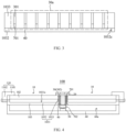
FIG. 2 is a schematic plan view of a first display unit and a vacuum valve in the splicing display device shown inFIG. 1 . -
FIG. 3 is a schematic cross-sectional view along a line A-A shown inFIG. 2 . -
FIG. 4 is a schematic cross-sectional view of a splicing display device according to another embodiment of the present disclosure. -
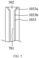
FIG. 5 is a partially enlarged schematic view of the splicing display device shown inFIG. 4 . - Technical solutions in the embodiments of the present disclosure will be clearly and completely described below with reference to the accompanying drawings in the embodiments of the present disclosure. Obviously, the described embodiments are only some, but not all, embodiments of the present disclosure. Based on the embodiments in the present disclosure, all other embodiments obtained by those skilled in the art without creative efforts shall fall within a protection scope of the present disclosure.
- Referring to
FIG. 1, FIG. 2 , andFIG. 3 , the present disclosure provides asplicing display device 100. Thesplicing display device 100 includes at least twofirst display units 10, asecond display unit 20, avacuum suction component 30, avacuum valve 40, avacuum unit 50, arear casing 60, a first connectingpipe 701, and a second connectingpipe 702. - The first display units10 are configured to display. Each of the
first display units 10 includes adisplay area 10a and anon-display area 10b. Thenon-display area 10b is disposed at a periphery of thedisplay area 10a and is arranged around thedisplay area 10a. - The first display units10 are liquid crystal display modules. Each of the
first display units 10 includes a liquidcrystal display panel 102 and abacklight module 103 disposed on a back side of a light-emitting surface of the liquidcrystal display panel 102. - The
backlight module 103 includes abackplane 1031, a light plate, a diffuser plate, an optical film, and the like. Thebackplane 1031 includes abottom plate 1032 and fourfirst side plates 1033. Thebottom plate 1032 is rectangular. The fourfirst side plates 1033 are arranged along four edges of thebottom plate 1032. The fourfirst side plates 1033 and thebottom plate 1032 are surrounded to form a firstaccommodating cavity 1031a. The light plate, the diffuser plate, and the optical film etc. are arranged in the firstaccommodating cavity 1031a. - The liquid
crystal display panel 102 is fixed on afirst side plate 1033 of thebackplane 1031. Thefirst side plate 1033 is disposed around the liquidcrystal display panel 102. A display area of the liquidcrystal display panel 102 is thedisplay area 10a of thefirst display unit 10. Thenon-display area 10b of thefirst display unit 10 includes a non-display area of the liquidcrystal display panel 102. Thenon-display area 10b of thefirst display units 10 is provided with thefirst side plate 1033 of thebackplane 1031. - It can be understood that the
first display units 10 may also be micro light emitting diode display devices, sub-millimeter light emitting diode display devices, organic light emitting diode display devices or quantum dot display devices. - At least two
first display units 10 may be spliced and connected along a same direction, or may be spliced and connected along two perpendicularly intersecting directions. Specifically, at least twofirst display units 10 are spliced and connected in the same direction. The two adjacent spliced first display units have a splicing position M. The splicing position M includes a splicing seam and thenon-display areas 10b of thefirst display units 10. - In order to prevent the splicing seam of the splicing position M of the two adjacent spliced first display units and the
non-display areas 10b of thefirst display units 10 from being viewed by human eyes, eachsecond display unit 20 is disposed on the light-emitting side of the first display units, and is attached and fixed to the splicing position M of thenon-display area 10b of the two adjacentfirst display units 10. - The
second display unit 20 is a light emitting-diode light panel. Thesecond display unit 20 includes a substrate and a plurality of inorganic light-emitting diodes arranged on the substrate. The substrate is a printed circuit board, and the inorganic light-emitting diodes can be micro light-emitting diodes or sub-millimeter light-emitting diodes. - The
splicing display device 100 further includes a flexible printedcircuit board 80 and acontrol circuit board 90. One end of the flexible printedcircuit board 80 is connected to a rear surface of the light-emitting surface of thesecond display unit 20, and another end of the flexible printedcircuit board 80 is connected to thecontrol circuit board 90, so that thecontrol circuit board 90 can control thesecond display unit 20 to emit light. - The
splicing display device 100 also includes amiddle frame 110. Themiddle frame 110 includes aframe body 1101 and foursecond side plates 1102 connected with theframe body 1101. Theframe body 1101 is a rectangular frame body. Theframe body 1101 is disposed on a side of the liquidcrystal display panel 102 away from thebacklight module 103 and is parallel to the liquidcrystal display panel 102. Theframe body 1101 is disposed in the non-display area of thesplicing display device 100. An opening of theframe body 1101 overlaps with thedisplay areas 10a of the at least twofirst display units 10 and thesecond display unit 20. The foursecond side plates 1102 are vertically connected to theframe body 1101. The foursecond side plates 1102 are disposed one-to-one with the fourfirst side plates 1033 and are disposed at a periphery of the fourfirst side plates 1033. Thesecond side plate 1102 is detachably fixed on thefirst side plate 1033. - The
rear casing 60 is disposed on a back side of the at least two splicedfirst display units 10. Therear casing 60 is detachably fixed to a rear surface of thefirst display units 10. Therear casing 60 includes a secondaccommodating cavity 60a. Specifically, therear casing 60 is detachably fixed on thebottom plate 1032 of thebackplane 1031. - In this embodiment, the splicing seam of the splicing position M and the
non-display areas 10b of thefirst display units 10 are blocked by thesecond display unit 20. Thesecond display unit 20 displays, which prevents the splicing seam of the splicing position M of the two adjacent spliced first display units and thenon-display areas 10b of thefirst display units 10 from being viewed by the human eye. Moreover, for bonding the second display unit and the first display unit with an adhesive layer with a thickness of millimeters, unevenness and fixing problems are caused due to the uneven thickness of the adhesive layer. Compared with the above, in this embodiment, since eachsecond display unit 20 is fixed to thenon-display area 10b of thefirst display unit 10 by suction, thesecond display unit 20 can be fixed to thenon-display area 10b of thefirst display unit 10 flatly, thereby improving the display performance of thesplicing display device 100. - The
vacuum suction component 30 is configured to attach thesecond display unit 20. Thevacuum suction component 30 is disposed in thenon-display area 10b of thefirst display unit 10, and is arranged corresponding to thesecond display unit 20. - Referring to
FIG. 2 andFIG. 3 , a group of thevacuum suction components 30a are correspondingly disposed in the splicing position M of thenon-display areas 10b of two adjacentfirst display units 10. The group of thevacuum suction components 30a includes a plurality of thevacuum suction components 30. - The plurality of
vacuum suction components 30 of the group ofvacuum suction components 30a are arranged side by side along an extending direction of the splicing seam. The plurality ofvacuum suction components 30 of the group ofvacuum suction components 30a may also be arranged in a single row, two rows, or multiple rows. The plurality ofvacuum suction components 30 of the group ofvacuum suction components 30a may also be arranged in a rectangular or other shape. - When the plurality of
vacuum suction components 30 of the group ofvacuum suction components 30a are arranged side by side along the extension direction of the splicing seam, a distance between any two adjacentvacuum suction components 30 is equal in the extension direction of the splicing seam. - Two groups of the
vacuum suction components 30a respectively disposed on the splicing position M of thenon-display areas 10b of the two adjacentfirst display units 10 are symmetrically arranged. Suction forces of the two groups of thevacuum suction components 30a to thesecond display unit 20 are the same, and thesecond display unit 20 can be fixed to thenon-display areas 10b of the two adjacentfirst display units 10 more smoothly. - The
vacuum suction component 30 includes asuction hole 301. Thesuction hole 301 is disposed on thefirst side plate 1033 of thebackplane 1031 close to the splicing seam. Thesuction hole 301 extends in a thickness direction of thefirst display units 10 and extends through thefirst side plate 1033. - The
suction hole 301 is a cylindrical hole. It can be understood that thesuction hole 301 may also be a quadrangular prism hole or a triangular prism hole. - The vacuuming
unit 50 is configured to vacuum thevacuum suction component 30. The vacuumingunit 50 is disposed on a side of thefirst display unit 10 away from thesecond display unit 20. The vacuumingunit 50 is arranged in the secondaccommodating cavity 60a of therear casing 60. The vacuumingunit 50 may be a vacuum compressor. - The
vacuum valve 40 is configured to adjust a negative pressure condition in thevacuum suction component 30. Thevacuum valve 40 is connected between thevacuum suction component 30 and the vacuumingunit 50. Onevacuum valve 40 is connected to one group of thevacuum suction components 30a. - Specifically, one ends of the plurality of first connecting
pipes 701 are connected to the plurality of first ends of thevacuum valves 40 one-to-one. Another ends of the first connectingpipe 701 are inserted into the suction holes 301. There is good sealing between the another end of the first connectingpipe 701 and thesuction hole 301, which is beneficial to maintain the negative pressure condition in thevacuum suction component 30. One end of the second connectingpipe 702 is connected to the second end of thevacuum valve 40. Another end of the second connectingpipe 702 is connected to the vacuumingunit 50. Both the first connectingpipe 701 and the second connectingpipe 702 are plastic flexible pipes, which can be configured to allow gas to pass through. - As shown in
FIG. 3 , thefirst display unit 10 includes a secondaccommodating slot 1032c. The secondaccommodating slot 1032c is disposed on a rear surface of thefirst display unit 10 away from thesecond display unit 20. The secondaccommodating slot 1032c corresponds to thevacuum suction component 30. Thevacuum valve 40 is detachably fixed in the secondaccommodating slot 1032c. - Specifically, the second
accommodating slot 1032c is disposed on a surface of thebottom plate 1032 of thebackplane 1031 away from the liquidcrystal display panel 102, and thevacuum valve 40 is disposed in the secondaccommodating slot 1032c. - It is understood that the
vacuum valve 40 may also be disposed in the secondaccommodating cavity 60a of therear casing 60. - In the splicing display device of this embodiment, the
suction hole 301 is vacuumed by the vacuumingunit 50, so that a pressure in thesuction hole 301 is lower than an atmospheric pressure. Under an action of a pressure difference between the pressure in thesuction hole 301 and the atmospheric pressure, thesecond display unit 20 is attached on thesuction hole 301, so that thesecond display unit 20 is attached and fixed to thenon-display area 10b of thefirst display unit 10. Moreover, thevacuum valve 40 can adjust the negative pressure condition in thesuction hole 301, thereby adjusting a flatness of thenon-display area 10b of thefirst display unit 10 where thesecond display unit 20 is attached and fixed to. - Referring to
FIG. 4 andFIG. 5 , the splicing display device shown inFIG. 4 is basically similar to the splicing display device shown inFIG. 1 ,a difference is that thefirst display unit 10 further includes a firstaccommodating slot 1033a and a throughhole 1033b. The firstaccommodating slot 1033a is disposed on a surface of thefirst display unit 10 adjacent to thesecond display unit 20. The firstaccommodating slot 1033a is disposed in thenon-display area 10b of thefirst display unit 10 and is arranged corresponding to thesecond display unit 20. The throughhole 1033b corresponds to the firstaccommodating slot 1033a and they are communicated with each other. The throughhole 1033b extends in a thickness direction of thefirst display units 10. Thevacuum suction component 30 includes avacuum sucker 302. Thevacuum sucker 302 is disposed in the firstaccommodating slot 1033a. The first connectingpipe 701 is disposed in the throughhole 1033b. One end of the first connecting pipe701 is connected to thevacuum sucker 302. Another end of the first connectingpipe 701 is connected to thevacuum valve 40. The second connectingpipe 702 connects thevacuum valve 40 and the vacuumingunit 50. The second connectingpipe 702 is disposed in the secondaccommodating cavity 60a of therear casing 60. - Specifically, the first
accommodating slot 1033a and the throughhole 1033b are disposed on thefirst side plate 1033 of thebackplane 1031. The firstaccommodating slot 1033a is disposed on a surface of thefirst side plate 1033 close to thesecond display unit 20. An area of a cross-section of the firstaccommodating slot 1033a in a direction parallel to thebottom plate 1032 decreases from being close to thesecond display unit 20 to being away from thesecond display unit 20. The firstaccommodating slot 1033a is funnel-shaped. The throughhole 1033b extends in the thickness direction of thefirst display units 10. The throughhole 1033b communicates with the firstaccommodating slot 1033a. A shape of thevacuum sucker 302 is the same as that of the firstaccommodating slot 1033a. Thevacuum sucker 302 is disposed in the firstaccommodating slot 1033a. One end of the first connectingpipe 701 is connected to vacuumsucker 302. Another end of the first connectingpipe 701 is connected to thevacuum valve 40. The second connectingpipe 702 connects thevacuum valve 40 and the vacuumingunit 50. The second connectingpipe 702 is disposed in the secondaccommodating cavity 60a of therear casing 60. - In this embodiment, the
vacuum sucker 302 is configured to attach thesecond display unit 20, which is beneficial to improve an attaching effect of thesecond display unit 20. - The descriptions of the above embodiments are only used to help understand the technical solutions and core ideas of the present disclosure. Those of ordinary skill in the art should understand that they can still make modifications to the technical solutions described in the foregoing embodiments, or perform equivalent replacements to some of the technical features. These modifications or replacements do not make the essence of the corresponding technical solutions deviate from the scope of the technical solutions of the various embodiments of the present disclosure.
Claims (20)
- A splicing display device, comprising:at least two first display units which are spliced and connected, wherein each of the first display units comprises a non-display area, and the first display units are liquid crystal display modules; anda second display unit disposed on a light-emitting side of the first display units, and attached and fixed to a splicing position of the non-display areas of the two adjacent first display units, wherein the second display unit comprises a substrate and a plurality of inorganic light-emitting diodes disposed on the substrate, and the inorganic light-emitting diodes are micro light-emitting diodes or sub-millimeter light-emitting diodes.
- The splicing display device according to claim 1, further comprising:a vacuum suction component disposed in the non-display area of one of the first display units and arranged corresponding to the second display unit, wherein the vacuum suction component is configured to attach the second display unit; anda vacuuming unit disposed on a side of the one of the first display units away from the second display unit, wherein the vacuuming unit is connected to the vacuum suction component, and is configured to vacuum the vacuum suction component.
- The splicing display device according to claim 2, wherein the vacuum suction component comprises a suction hole, and the suction hole extends in a thickness direction of the first display units; and
the splicing display device further comprises a connecting pipe, one end of the connecting pipe is connected to the vacuuming unit, and another end of the connecting pipe is inserted into the suction hole. - The splicing display device according to claim 2, wherein each of the first display units further comprises:a first accommodating slot disposed in the non-display area of the first display unit, disposed on a surface of the first display unit close to the second display unit, and arranged corresponding to the second display unit; anda through hole correspondingly arranged and communicated with the first accommodating slot, and extending in a thickness direction of the first display unit;wherein the vacuum suction component comprises a vacuum sucker and is disposed in the first accommodating slot; andwherein the splicing display device further comprises a connecting pipe, at least a portion of the connecting pipe is disposed in the through hole, one end of the connecting pipe is connected to the vacuum sucker, and another end of the connecting pipe is connected to the vacuuming unit.
- The splicing display device according to claim 1, wherein each of the first display units comprises a liquid crystal display panel and a backlight module, the backlight module comprises a backplane, the backplane comprises a bottom plate and a side plate arranged along an edge of the bottom plate, the side plate of the backplane is arranged around the liquid crystal display panel, the side plate of the backplane is disposed in the non-display area of the first display unit, and the vacuum suction component is disposed in the side plate.
- The splicing display device according to claim 2, further comprising: a vacuum valve connected between the vacuum suction component and the vacuuming unit.
- The splicing display device according to claim 6, wherein a group of the vacuum suction components is correspondingly disposed on the splicing position of the non-display area of one of the two adjacent first display units, the group of the vacuum suction components comprises a plurality of the vacuum suction components, one of the vacuum valves is connected to the group of the vacuum suction components.
- The splicing display device according to claim 7, wherein two groups of the vacuum suction components respectively disposed on the splicing position of the non-display areas of the two adjacent first display units are symmetrically arranged.
- A splicing display device, comprising:at least two first display units which are spliced and connected, wherein each of the first display units comprises a non-display area; anda second display unit disposed on a light-emitting side of the first display units, and attached and fixed to a splicing position of the non-display areas of the two adjacent first display units.
- The splicing display device according to claim 9, further comprising:a vacuum suction component disposed in the non-display area of one of the first display units and arranged corresponding to the second display unit, wherein the vacuum suction component is configured to attach the second display unit; anda vacuuming unit disposed on a side of the one of the first display units away from the second display unit, wherein the vacuuming unit is connected to the vacuum suction component, and is configured to vacuum the vacuum suction component.
- The splicing display device according to claim 10, wherein the vacuum suction component comprises a suction hole, and the suction hole extends in a thickness direction of the first display units; and
the splicing display device further comprises a connecting pipe, one end of the connecting pipe is connected to the vacuuming unit, and another end of the connecting pipe is inserted into the suction hole. - The splicing display device according to claim 10, wherein each of the first display units further comprises:a first accommodating slot disposed in the non-display area of the first display unit, disposed on a surface of the first display unit close to the second display unit, and arranged corresponding to the second display unit; anda through hole correspondingly arranged and communicated with the first accommodating slot, and extending in a thickness direction of the first display unit;wherein the vacuum suction component comprises a vacuum sucker and is disposed in the first accommodating slot; andwherein the splicing display device further comprises a connecting pipe, at least a portion of the connecting pipe is disposed in the through hole, one end of the connecting pipe is connected to the vacuum sucker, and another end of the connecting pipe is connected to the vacuuming unit.
- The splicing display device according to claim 10, wherein the first display units are liquid crystal display modules, and the second display unit is a light emitting-diode light panel.
- The splicing display device according to claim 13, wherein each of the first display units comprises a liquid crystal display panel and a backlight module, the backlight module comprises a backplane, the backplane comprises a bottom plate and a side plate arranged along an edge of the bottom plate, the side plate of the backplane is arranged around the liquid crystal display panel, the side plate of the backplane is disposed in the non-display area of the first display unit, and the vacuum suction component is disposed in the side plate.
- The splicing display device according to claim 10, further comprising: a vacuum valve connected between the vacuum suction component and the vacuuming unit.
- The splicing display device according to claim 15, wherein a group of the vacuum suction components is correspondingly disposed on the splicing position of the non-display area of one of the two adjacent first display units, the group of the vacuum suction components comprises a plurality of the vacuum suction components, one of the vacuum valves is connected to the group of the vacuum suction components.
- The splicing display device according to claim 16, wherein two groups of the vacuum suction components respectively disposed on the splicing position of the non-display areas of the two adjacent first display units are symmetrically arranged.
- The splicing display device according to claim 16, wherein the plurality of the vacuum suction components of the group of the vacuum suction components are arranged side by side along an extending direction of a splicing seam of the splicing position.
- The splicing display device according to claim 15, wherein each of the first display units comprises a second accommodating slot disposed on a rear surface of the first display unit away from the second display unit;
wherein the vacuum valve is detachably fixed in the second accommodating slot. - The splicing display device according to claim 15, further comprising: a rear casing disposed on a back side of light-emitting surfaces of at least two of the first display units which are spliced, wherein the rear casing comprises an accommodating cavity, and the vacuum valve and the vacuuming unit are arranged in the accommodating cavity of the rear casing.
Applications Claiming Priority (2)
| Application Number | Priority Date | Filing Date | Title |
|---|---|---|---|
| CN202210710895.2A CN115116346B (en) | 2022-06-22 | 2022-06-22 | Spliced display device |
| PCT/CN2022/103119 WO2023245717A1 (en) | 2022-06-22 | 2022-06-30 | Tiled display device |
Publications (2)
| Publication Number | Publication Date |
|---|---|
| EP4546314A1 true EP4546314A1 (en) | 2025-04-30 |
| EP4546314A4 EP4546314A4 (en) | 2026-04-08 |
Family
ID=83328210
Family Applications (1)
| Application Number | Title | Priority Date | Filing Date |
|---|---|---|---|
| EP22741145.1A Pending EP4546314A4 (en) | 2022-06-22 | 2022-06-30 | MOSAIC DISPLAY DEVICE |
Country Status (5)
| Country | Link |
|---|---|
| US (1) | US12386218B2 (en) |
| EP (1) | EP4546314A4 (en) |
| JP (1) | JP7614214B2 (en) |
| CN (1) | CN115116346B (en) |
| WO (1) | WO2023245717A1 (en) |
Families Citing this family (1)
| Publication number | Priority date | Publication date | Assignee | Title |
|---|---|---|---|---|
| CN114446194B (en) * | 2020-10-30 | 2025-03-18 | 京东方科技集团股份有限公司 | Stackable display device |
Family Cites Families (21)
| Publication number | Priority date | Publication date | Assignee | Title |
|---|---|---|---|---|
| JP2002062826A (en) * | 2000-08-16 | 2002-02-28 | Sony Corp | Tiling display manufacturing apparatus and method, and tiling display |
| CN103065551B (en) * | 2013-01-16 | 2015-07-15 | 深圳市华星光电技术有限公司 | Spliced display screen |
| CN105044959B (en) * | 2015-09-14 | 2019-04-05 | 深圳市华星光电技术有限公司 | It is a kind of that seamless spliced multi-display apparatus can be achieved |
| US11196941B2 (en) * | 2017-06-12 | 2021-12-07 | Christie Digital Systems Usa, Inc. | Fixture for aligning tiled displays |
| CN110379314B (en) * | 2019-07-23 | 2020-10-16 | 深圳市华星光电半导体显示技术有限公司 | Seamless splicing screen |
| CN111128051A (en) * | 2020-01-21 | 2020-05-08 | 深圳市华星光电半导体显示技术有限公司 | Large-size display and splicing method thereof |
| CN111290154A (en) * | 2020-02-24 | 2020-06-16 | 京东方科技集团股份有限公司 | Display device and spliced screen |
| KR102788991B1 (en) * | 2020-05-12 | 2025-03-31 | 삼성디스플레이 주식회사 | Tiled display device |
| GB202009342D0 (en) * | 2020-06-18 | 2020-08-05 | Barco Nv | System and method for display diffuser |
| CN111653207B (en) * | 2020-07-30 | 2022-12-13 | 上海天马微电子有限公司 | Display module assembly, display device and spliced screen |
| US11887842B2 (en) | 2020-08-24 | 2024-01-30 | PlayNitride Display Co., Ltd. | Spliced micro light-emitting-diode display panel |
| CN113270049A (en) * | 2021-04-28 | 2021-08-17 | 惠州视维新技术有限公司 | Display device |
| CN113703211B (en) * | 2021-08-16 | 2023-02-03 | Tcl华星光电技术有限公司 | Tiled display device |
| CN215577444U (en) * | 2021-09-06 | 2022-01-18 | 深圳市唯奥视讯技术有限公司 | Seamless display device of many screens concatenation |
| CN113763823B (en) * | 2021-11-10 | 2022-04-01 | Tcl华星光电技术有限公司 | Splicing display panel and splicing display device |
| CN114038340B (en) | 2021-11-29 | 2023-10-13 | 深圳市华星光电半导体显示技术有限公司 | Spliced display device and spliced display screen |
| CN114141154B (en) * | 2021-12-06 | 2023-06-02 | Tcl华星光电技术有限公司 | Spliced display device |
| CN114283698B (en) * | 2021-12-20 | 2023-05-30 | Tcl华星光电技术有限公司 | Spliced display panel and electronic equipment |
| CN114415410A (en) | 2022-01-27 | 2022-04-29 | 惠州华星光电显示有限公司 | Splicing display module and display device |
| CN114488621A (en) * | 2022-03-11 | 2022-05-13 | 惠州华星光电显示有限公司 | Spliced light-emitting panel, backlight module and spliced display panel |
| WO2023230879A1 (en) * | 2022-05-31 | 2023-12-07 | 京东方科技集团股份有限公司 | Display module, spliced screen and display apparatus |
-
2022
- 2022-06-22 CN CN202210710895.2A patent/CN115116346B/en active Active
- 2022-06-30 WO PCT/CN2022/103119 patent/WO2023245717A1/en not_active Ceased
- 2022-06-30 EP EP22741145.1A patent/EP4546314A4/en active Pending
- 2022-06-30 JP JP2022552431A patent/JP7614214B2/en active Active
- 2022-06-30 US US17/793,397 patent/US12386218B2/en active Active
Also Published As
| Publication number | Publication date |
|---|---|
| EP4546314A4 (en) | 2026-04-08 |
| US20250116895A1 (en) | 2025-04-10 |
| US12386218B2 (en) | 2025-08-12 |
| JP2024530060A (en) | 2024-08-15 |
| CN115116346B (en) | 2023-10-17 |
| CN115116346A (en) | 2022-09-27 |
| JP7614214B2 (en) | 2025-01-15 |
| WO2023245717A1 (en) | 2023-12-28 |
Similar Documents
| Publication | Publication Date | Title |
|---|---|---|
| US20220167509A1 (en) | Display device and formation method thereof | |
| KR102652758B1 (en) | Display apparatus and method of manufacturing thereof | |
| US9280009B2 (en) | Double-sided curved liquid crystal display device | |
| US20090310335A1 (en) | Light source device and display device having the same | |
| US20150370113A1 (en) | Display module and multi-display device having the same | |
| US11506821B2 (en) | Optical adhesive layer, stretchable display device and preparing method for optical adhesive layer | |
| CN101256305A (en) | Backlight assembly and display device with the backlight assembly | |
| CN112419890A (en) | Backboard and display device | |
| KR20090096201A (en) | Display device unit and multi display device including the same | |
| CN102087814A (en) | Borderless display device and large screen displayer | |
| CN108346379B (en) | Display assembly, display assembly attaching method and flat panel display | |
| KR20180004464A (en) | Display device | |
| WO2022116304A1 (en) | Display panel, method for manufacturing same, and display screen | |
| US12386218B2 (en) | Splicing display device | |
| CN112015003B (en) | Display device | |
| US8836886B2 (en) | Frameless liquid crystal display device | |
| US20230282138A1 (en) | Display panel and light board | |
| CN107340644A (en) | Backlight module and the liquid crystal display with the backlight module | |
| US12255186B2 (en) | Splicing display device | |
| KR20180004463A (en) | Display device | |
| CN107505771A (en) | Backlight module and the liquid crystal display with the backlight module | |
| KR102396604B1 (en) | Liquid crystal display device | |
| KR20140114960A (en) | Liquid crystal display device moudle and mobile device including the same | |
| CN102141646B (en) | Backlight module and light guide plate module | |
| CN203686786U (en) | Backlight module and display device |
Legal Events
| Date | Code | Title | Description |
|---|---|---|---|
| STAA | Information on the status of an ep patent application or granted ep patent |
Free format text: STATUS: UNKNOWN |
|
| STAA | Information on the status of an ep patent application or granted ep patent |
Free format text: STATUS: THE INTERNATIONAL PUBLICATION HAS BEEN MADE |
|
| PUAI | Public reference made under article 153(3) epc to a published international application that has entered the european phase |
Free format text: ORIGINAL CODE: 0009012 |
|
| STAA | Information on the status of an ep patent application or granted ep patent |
Free format text: STATUS: REQUEST FOR EXAMINATION WAS MADE |
|
| 17P | Request for examination filed |
Effective date: 20220727 |
|
| AK | Designated contracting states |
Kind code of ref document: A1 Designated state(s): AL AT BE BG CH CY CZ DE DK EE ES FI FR GB GR HR HU IE IS IT LI LT LU LV MC MK MT NL NO PL PT RO RS SE SI SK SM TR |
|
| DAV | Request for validation of the european patent (deleted) | ||
| DAX | Request for extension of the european patent (deleted) | ||
| REG | Reference to a national code |
Ref country code: DE Ref legal event code: R079 Free format text: PREVIOUS MAIN CLASS: G09F0009302000 Ipc: G02F0001133300 |
|
| A4 | Supplementary search report drawn up and despatched |
Effective date: 20260310 |
|
| RIC1 | Information provided on ipc code assigned before grant |
Ipc: G02F 1/1333 20060101AFI20260304BHEP |