EP4545976A1 - Sample condition assessing device, sample condition assessing method, and sample testing device - Google Patents
Sample condition assessing device, sample condition assessing method, and sample testing device Download PDFInfo
- Publication number
- EP4545976A1 EP4545976A1 EP23826976.5A EP23826976A EP4545976A1 EP 4545976 A1 EP4545976 A1 EP 4545976A1 EP 23826976 A EP23826976 A EP 23826976A EP 4545976 A1 EP4545976 A1 EP 4545976A1
- Authority
- EP
- European Patent Office
- Prior art keywords
- container
- boundary position
- specimen
- processor
- image
- Prior art date
- Legal status (The legal status is an assumption and is not a legal conclusion. Google has not performed a legal analysis and makes no representation as to the accuracy of the status listed.)
- Pending
Links
Images




Classifications
-
- G—PHYSICS
- G06—COMPUTING OR CALCULATING; COUNTING
- G06T—IMAGE DATA PROCESSING OR GENERATION, IN GENERAL
- G06T7/00—Image analysis
- G06T7/10—Segmentation; Edge detection
- G06T7/12—Edge-based segmentation
-
- G—PHYSICS
- G01—MEASURING; TESTING
- G01N—INVESTIGATING OR ANALYSING MATERIALS BY DETERMINING THEIR CHEMICAL OR PHYSICAL PROPERTIES
- G01N15/00—Investigating characteristics of particles; Investigating permeability, pore-volume or surface-area of porous materials
- G01N15/04—Investigating sedimentation of particle suspensions
- G01N15/05—Investigating sedimentation of particle suspensions in blood
-
- G—PHYSICS
- G01—MEASURING; TESTING
- G01N—INVESTIGATING OR ANALYSING MATERIALS BY DETERMINING THEIR CHEMICAL OR PHYSICAL PROPERTIES
- G01N33/00—Investigating or analysing materials by specific methods not covered by groups G01N1/00 - G01N31/00
- G01N33/48—Biological material, e.g. blood, urine; Haemocytometers
- G01N33/483—Physical analysis of biological material
- G01N33/487—Physical analysis of biological material of liquid biological material
- G01N33/49—Blood
-
- G—PHYSICS
- G01—MEASURING; TESTING
- G01N—INVESTIGATING OR ANALYSING MATERIALS BY DETERMINING THEIR CHEMICAL OR PHYSICAL PROPERTIES
- G01N35/00—Automatic analysis not limited to methods or materials provided for in any single one of groups G01N1/00 - G01N33/00; Handling materials therefor
- G01N35/00584—Control arrangements for automatic analysers
- G01N35/00722—Communications; Identification
- G01N35/00732—Identification of carriers, materials or components in automatic analysers
-
- G—PHYSICS
- G01—MEASURING; TESTING
- G01N—INVESTIGATING OR ANALYSING MATERIALS BY DETERMINING THEIR CHEMICAL OR PHYSICAL PROPERTIES
- G01N35/00—Automatic analysis not limited to methods or materials provided for in any single one of groups G01N1/00 - G01N33/00; Handling materials therefor
- G01N35/10—Devices for transferring samples or any liquids to, in, or from, the analysis apparatus, e.g. suction devices, injection devices
- G01N35/1009—Characterised by arrangements for controlling the aspiration or dispense of liquids
- G01N35/1016—Control of the volume dispensed or introduced
-
- G—PHYSICS
- G06—COMPUTING OR CALCULATING; COUNTING
- G06T—IMAGE DATA PROCESSING OR GENERATION, IN GENERAL
- G06T7/00—Image analysis
- G06T7/0002—Inspection of images, e.g. flaw detection
- G06T7/0004—Industrial image inspection
-
- G—PHYSICS
- G06—COMPUTING OR CALCULATING; COUNTING
- G06V—IMAGE OR VIDEO RECOGNITION OR UNDERSTANDING
- G06V20/00—Scenes; Scene-specific elements
- G06V20/60—Type of objects
- G06V20/69—Microscopic objects, e.g. biological cells or cellular parts
- G06V20/695—Preprocessing, e.g. image segmentation
-
- G—PHYSICS
- G01—MEASURING; TESTING
- G01N—INVESTIGATING OR ANALYSING MATERIALS BY DETERMINING THEIR CHEMICAL OR PHYSICAL PROPERTIES
- G01N35/00—Automatic analysis not limited to methods or materials provided for in any single one of groups G01N1/00 - G01N33/00; Handling materials therefor
- G01N35/00584—Control arrangements for automatic analysers
- G01N35/00722—Communications; Identification
- G01N35/00732—Identification of carriers, materials or components in automatic analysers
- G01N2035/00742—Type of codes
- G01N2035/00752—Type of codes bar codes
-
- G—PHYSICS
- G01—MEASURING; TESTING
- G01N—INVESTIGATING OR ANALYSING MATERIALS BY DETERMINING THEIR CHEMICAL OR PHYSICAL PROPERTIES
- G01N35/00—Automatic analysis not limited to methods or materials provided for in any single one of groups G01N1/00 - G01N33/00; Handling materials therefor
- G01N35/02—Automatic analysis not limited to methods or materials provided for in any single one of groups G01N1/00 - G01N33/00; Handling materials therefor using a plurality of sample containers moved by a conveyor system past one or more treatment or analysis stations
- G01N35/04—Details of the conveyor system
- G01N2035/0401—Sample carriers, cuvettes or reaction vessels
- G01N2035/0406—Individual bottles or tubes
-
- G—PHYSICS
- G01—MEASURING; TESTING
- G01N—INVESTIGATING OR ANALYSING MATERIALS BY DETERMINING THEIR CHEMICAL OR PHYSICAL PROPERTIES
- G01N35/00—Automatic analysis not limited to methods or materials provided for in any single one of groups G01N1/00 - G01N33/00; Handling materials therefor
- G01N35/10—Devices for transferring samples or any liquids to, in, or from, the analysis apparatus, e.g. suction devices, injection devices
- G01N35/1009—Characterised by arrangements for controlling the aspiration or dispense of liquids
- G01N35/1016—Control of the volume dispensed or introduced
- G01N2035/1018—Detecting inhomogeneities, e.g. foam, bubbles, clots
-
- G—PHYSICS
- G01—MEASURING; TESTING
- G01N—INVESTIGATING OR ANALYSING MATERIALS BY DETERMINING THEIR CHEMICAL OR PHYSICAL PROPERTIES
- G01N35/00—Automatic analysis not limited to methods or materials provided for in any single one of groups G01N1/00 - G01N33/00; Handling materials therefor
- G01N35/10—Devices for transferring samples or any liquids to, in, or from, the analysis apparatus, e.g. suction devices, injection devices
- G01N35/1009—Characterised by arrangements for controlling the aspiration or dispense of liquids
- G01N2035/1025—Fluid level sensing
-
- G—PHYSICS
- G06—COMPUTING OR CALCULATING; COUNTING
- G06T—IMAGE DATA PROCESSING OR GENERATION, IN GENERAL
- G06T2207/00—Indexing scheme for image analysis or image enhancement
- G06T2207/10—Image acquisition modality
- G06T2207/10024—Color image
-
- G—PHYSICS
- G06—COMPUTING OR CALCULATING; COUNTING
- G06T—IMAGE DATA PROCESSING OR GENERATION, IN GENERAL
- G06T2207/00—Indexing scheme for image analysis or image enhancement
- G06T2207/20—Special algorithmic details
- G06T2207/20084—Artificial neural networks [ANN]
Definitions
- the present invention relates to a specimen condition assessing device, a specimen condition assessing method, and a specimen testing device, and relates to an image processing technology using machine learning which is for, e.g., detecting and identifying a specific inclusion in a specimen (such as, e.g., a serum (blood plasma)) included in a photographed image.
- a specimen such as, e.g., a serum (blood plasma)
- a plurality of color extraction means are used to detect upper and lower boundary positions of a serum.
- saturation information is used to determine a boundary position between a serum portion and another portion and calculate an amount of the serum.
- a mechanism that emits and receives an infrared ray is vertically moved to detect respective positions of a separating agent, a serum, and a blood clot.
- the present invention has been achieved in view of such circumstances and provides a technology that allows boundary positions of a serum (blood plasma) or the like in an image to be detected and allows whether or not a specimen container is testable to be precisely assessed.
- a specimen condition assessing device includes a processor that executes a program for performing image processing on an image of a target specimen container and a memory for storing a result of the image processing.
- the processor performs processing of inputting the image, processing of detecting one or more boundary position from the image, processing of determining a property (type) of upper and lower regions of each of the one or more boundary positions and determining a boundary position of each inclusion, and processing of assessing whether or not the target specimen container is testable on the basis of the determined boundary position of each inclusion.
- An embodiment of the present description provides a specimen condition assessing device and a specimen condition assessing method that detect boundary positions of a plurality of inclusions, while determining a type (property) of each of the inclusions around each of the boundary positions, further calculate a content thereof, while correcting the boundary position, and determine the presence or absence of each of the inclusions (such as, e.g., a serum (blood plasma), a separating agent, a blood clot, and urine) of a sample in a container on the basis of the plurality of boundary positions and a result of the determination of the inclusion to thereby implement high-precision determination of the content of each of the inclusions (such as, e.g., the serum (blood plasma), separating agent, blood clot, and urine) and assessment of whether or not a target sample container is testable.
- the inclusions such as, e.g., a serum (blood plasma), separating agent, blood clot, and urine
- each of the embodiments of the present invention may also be implemented using software operating on a versatile computer or may also be implemented using dedicated hardware or a combination of software and hardware.
- each processing in the embodiments of the present invention by using "Each of processing units (such as, e.g., an inclusion determining unit) as a program” as a subject (operating entity) but, since the program performs determined processing while using a memory and a communication port (communication control device) by being executed by a processor (such as a CPU), the description may also be given by using the processor as the subject.
- processing units such as, e.g., an inclusion determining unit
- a program performs determined processing while using a memory and a communication port (communication control device) by being executed by a processor (such as a CPU)
- a processor such as a CPU
- a specimen condition assessing device in one of the embodiments of the present description may also include a function of detecting a boundary position in a container and determining an inclusion and a function of assessing a condition of a specimen container.
- the specimen container is a combination of a container and a specimen contained in the container.
- the specimen condition assessing device may further include a function of correcting the boundary position.
- the embodiment in the present description detects the boundary position even when there is an air bubble or the like in the vicinity of the boundary position, determines the inclusions, the air bubble, and the like around the boundary position, analyzes the likelihood of a boundary around the boundary position in detail, and corrects the boundary position.
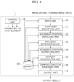
- Fig. 1 is a block diagram illustrating a functional configuration of a specimen condition assessing device according to the embodiment.
- the specimen condition assessing device 1 includes an input unit 10, a container identifying unit 11, a boundary position detecting unit 12, an inclusion determining unit 13, a boundary position correcting unit 14, a content calculating unit 15, a sample condition assessing unit 16, a control unit 19, and a memory 90. Note that, in the specimen condition assessing device, when container information has been given in advance, the container identifying unit 11 is not an essential component.
- the specimen condition assessing device 1 may also be mounted in a sample testing device, as will be described later (second embodiment). The embodiments described hereinbelow are applicable also to a specimen different from a sample collected from a human.
- the container identifying unit 11, the boundary position detecting unit 12, the inclusion determining unit 13, the boundary position correcting unit 14, the content calculating unit 15, and the sample condition assessing unit 16 may be implemented by programs or may also be implemented by being modularized.
- image data is input.
- the input unit 10 may acquire encoded still image data in a JPG, Jpeg 2000, PNG, BMP, or like format resulting from image capturing performed at predetermined time intervals by an image capturing means, such as a camera built in an image acquiring device, and use an image thereof as an input image.
- the input unit 10 may also extract the still image data of frames at predetermined intervals from dynamic image data in a Motion JPEG, MPEG, H. 264, HD/SDI, or like format, and use an image thereof as the input image.
- the input unit 10 may also use an image acquired by the image capturing means via a bus, a network, or the like as the input image.
- the input unit 10 may also use an image already stored in a detachable recording medium as the input image.
- the image input from the input unit 10 is output via the memory 90 to the container identifying unit 11, the boundary position detecting unit 12, the inclusion determining unit 13, and the boundary position correcting unit 14.
- the container identifying unit 11 uses a network that detects the entire container or a portion of the container (e.g., a container detector such as YOLO) to detect the container from the input image and identify the input image. In addition, the container identifying unit 11 stores the calculated container information in the memory 90.
- a container detector such as YOLO
- the boundary position detecting unit 12 uses a network that detects each boundary position and barcode boundaries (e.g., a boundary position detector such as YOLO) to detect each boundary position and the barcode boundaries from the input image.
- the boundary position is an interface between individual inclusions or between each inclusion and another substance.
- the barcode represents, e.g., information on a sample or a patient from which the sample has been collected.
- the boundary position detecting unit 12 stores, in the memory 90, calculated information such as each boundary position and the barcode boundaries.
- the inclusion determining unit 13 uses an identifier formed of a network (such as, e.g., Convolutional Neural Network) that identifies inclusions (such as, e.g., a serum (blood plasma), a separating agent, a blood clot, and urine) in upper and lower regions of each boundary position and the barcode each detected by the boundary position detecting unit 12, an object other than the inclusions (such as, e.g., background), and the barcode to calculate an identification result of the upper and lower regions of each boundary position and the barcode.
- the inclusion determining unit 13 stores, in the memory 90, information such as the calculated identification result of the upper and lower regions of each boundary position and the barcode.
- the boundary position correcting unit 14 uses an identifier formed of a network (such as, e.g., Convolutional Neural Network) that identifies each boundary position in detail to identify a periphery of each boundary position detected by the boundary position detecting unit 12 in detail, detect a precise boundary position, and correct the boundary position.
- the boundary position correcting unit 14 uses an identifier formed of a network (such as, e.g., Convolutional Neural Network) that identifies the presence or absence of a bubble around each boundary position to identify the presence or absence of a bubble and correct, when there is a bubble, the boundary position to a lowermost end of the bubble.
- the boundary position correcting unit 14 stores, in the memory 90, information such as each corrected boundary position.
- the content calculating unit 15 calculates a content of the target inclusion (such as, e.g., the serum (blood plasma), separating agent, blood clot, or urine) in the container from each boundary position corrected by the boundary position correcting unit 14 and container information or container information identified by the container identifying unit 11.
- the content calculating unit 15 stores, in the memory 90, information such as the calculated content of each of the inclusions in the container.
- the sample condition assessing unit 16 uses the content calculated by the content calculating unit 15 or the identification result of the individual regions obtained by the inclusion determining unit 13 to assess whether or not the target sample container (container containing a sample) is testable. In addition, the sample condition assessing unit 16 stores, in the memory 90, information such as a result of assessing whether or not the target container is testable.
- the control unit 19 is implemented by a processor and connected to each of elements in the specimen condition assessing device 1.
- An operation of each of the elements of the specimen condition assessing device 1 is implemented by an autonomous operation of each of the components described above or according to an instruction from the control unit 19.
- the container identifying unit 11 identifies a type of the container.
- the boundary position detecting unit 12 detects each boundary position in the container and the barcode boundary positions.
- the inclusion determining unit 13 calculates the identification result of the upper and lower regions of each boundary position in the container and the barcode.
- the boundary position correcting unit 14 identifies the periphery of each boundary position in detail to correct the boundary position, while the content calculating unit 15 calculates the content of the target inclusion in the container.
- the sample condition assessing unit 16 uses the calculated content and the identification result of the peripheral regions of each boundary position to assess a condition of a sample in the container, thereby detect the content of the inclusion in the container from the image with high precision, and assess whether or not the target container is testable.
- Fig. 2 is a diagram illustrating an example of a hardware configuration of the specimen condition assessing device 1 according to the embodiment of the present invention.
- the specimen condition assessing device 1 includes a CPU (processor) 201 that executes various programs, a memory 202 that stores the various programs, a storage device (corresponding to the memory 90) 203 that stores various data, an output device 204 for outputting each boundary position, each content, the result of assessing whether or not the target container is testable, and the like, and an input device 205 for inputting an instruction from a user, an image, and the like, which are connected to each other via a bus 207.
- a CPU processor
- memory 202 that stores the various programs
- a storage device corresponding to the memory 90
- an output device 204 for outputting each boundary position, each content, the result of assessing whether or not the target container is testable, and the like
- an input device 205 for inputting an instruction from a user, an image, and the like, which are connected to each other via a bus 207.
- the CPU 201 reads the various programs from the memory 202 as necessary, and executes the programs.
- the memory 202 stores the input unit 10, the container identifying unit 11, the boundary position detecting unit 12, the inclusion determining unit 13, the boundary position correcting unit 14, the content calculating unit 15, and the sample condition assessing unit 16 each as the program.
- the storage device 203 stores the input image, information on the type of the container identified by the container identifying unit 11, information on each boundary position in the container and the barcode boundary positions each detected by the boundary position detecting unit 12, the identification result of the upper and lower regions of each boundary position in the container and the barcode that is determined by the inclusion determining unit 13, information on the boundary position corrected by the boundary position correcting unit 14, information on the content of the target inclusion in the container calculated by the content calculating unit 15, the result of the assessment of whether or not the target container is testable performed by the sample condition assessing unit 16, and the like.
- the output device 204 is configured to include devices such as a display, a printer, and a speaker.
- the output device 204 displays, on a display screen, data generated by the container identifying unit 11, the boundary position detecting unit 12, the inclusion determining unit 13, the boundary position correcting unit 14, the content calculating unit 15, and the sample condition assessing unit 16.
- the input device 205 is configured to include devices such as a keyboard, a mouse, and a microphone. By the input device 205, instructions (including determination of the inputting of the input image) from the user are input to the specimen condition assessing device 1.
- the specimen condition determining device of the present invention identifies the container type, detects each boundary position in the container and the barcode boundary positions, calculates the identification result of the upper and lower regions of each boundary position in the container and the barcode, identifies the periphery of each boundary position in detail to correct the boundary position, calculates the content of the target inclusion in the container, and further assesses the condition of the sample in the container by using the calculated content and the identification result of the peripheral regions of each boundary position to thereby precisely assessing whether or not the target container is testable, while detecting the content of the inclusion in the container from the image with high precision.
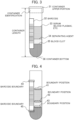
- Fig. 3 illustrates an example of the container.
- the container identifying unit 11 uses a network (a container detector such as, e.g., YOLO) that detects the entire container or a portion of the container to detect and identify the container from the input image, and determine a container type ct and a position of a container upper portion 31, while calculating a position of a container bottom 36 in the image, which is illustrated in Fig. 3 , from the calculated container type ct and container information in the memory 90.
- the container identifying unit 11 stores, in the memory 90, information on the identified container type and the respective positions of the container upper portion and the container bottom in the image.
- the boundary position detecting unit 12 detects the boundary positions (interfaces or boundaries) of the individual inclusions in the container and the barcode boundaries.
- Fig. 3 illustrates a barcode 32, a serum 33, a separating agent 34, and a blood clot 35.
- Fig. 4 illustrates an example of boundary position detection.
- the boundary position detecting unit 12 uses a network (such as a boundary position detector such as, e.g., YOLO) that detects each of the boundary positions (such as the boundaries of the inclusions) in the container and the barcode boundaries to detect each of the boundary positions and the boundaries of the barcode 32 from the input image as illustrated in Fig. 4 .
- a network such as a boundary position detector such as, e.g., YOLO
- a boundary 41 between the serum (blood plasma) 33 and the background, a boundary 42 between the serum 33 and the separating agent 34, and a boundary 43 between the blood clot and the separating agent are detected.
- an upper boundary 44 and a lower boundary 45 of the barcode 32 are detected.
- the boundary position detecting unit 12 sets 0 to a boundary position detection result lr and stores the boundary position detection result lr in the memory.
- the boundary position detecting unit 12 sets the number of the detected boundaries to the boundary position detection result lr.
- the boundary position detecting unit 12 stores, in the memory 90, the calculated boundary position detection results lr and information on each of the detected boundary positions.
- the inclusion determining unit 13 uses an identifier formed of a network (such as, e.g., Convolutional Neural Network) that identifies inclusions (inclusions such as, e.g., the serum (blood plasma), separating agent, blood clod, and urine) and objects other than the inclusions (such as, e.g., the background and the barcode) to calculate, for the upper and lower regions of each of the boundary positions and the barcode each detected by the boundary position detecting unit 12, the identification result of the upper and lower regions of each boundary position and the barcode.
- a network such as, e.g., Convolutional Neural Network
- the inclusion determining unit 13 uses information on the container type identified by the container identifying unit 11 to select an identifier appropriate for the container, and uses the selected identifier to calculate the identification result of the upper and lower regions of each boundary position and the barcode.
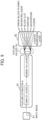
- Fig. 9 illustrates an example of obtention of the identification result.
- An input image A1 is input to a feature extractor A91, and feature values FAi are output therefrom.
- a logistic regression layer 92 identifies a region in the input image A1 on the basis of the feature values FAi.
- CNN represents Convolutional Neural Network.
- the inclusion determining unit 13 reads, from the memory 90, a weight w, a filter coefficient wj, and offset values b and bi in Expressions (1) and (2).
- the feature values FAi of the inclusions are obtained on the basis of Expression (1).
- the filter coefficient wj shown in Expression (1) is a coefficient determined by machine learning or the like so as to identify each of the inclusions (such as, e.g., the serum (blood plasma), separating agent, blood clot, and urine) as such and so as to identify each of the objects other than the inclusions (such as, e.g., the background and barcode) as such.
- the inclusions such as, e.g., the serum (blood plasma), separating agent, blood clot, and urine
- Expression (1) pj represents a pixel value, bi represents an offset value, m represents the number of filter coefficients, and h represents a non-linear function.
- a calculation result of each of filters is obtained to obtain feature values fi of any filter i.
- a matrix of the feature values fi obtained by the feature extractor A91 are the feature values FAi of the input image A1.
- the logistic regression layer 92 of the identifier calculates a value of the likelihood of each of the inclusions and the objects other than the inclusions to be detected (such as the likelihood of the serum (blood plasma), the likelihood of the separating agent, the likelihood of the blood clot, the likelihood of the background, and the likelihood of the barcode) on the basis of Expression (2) to determine whether or not each of the regions in the input image A1 (e.g., the upper and lower regions of the boundary positions) is the inclusion to be detected (such as, e.g., the serum (blood plasma), separating agent, blood clot, or urine) or the object other than the inclusions to be detected (such as, e.g., the background or the barcode).
- the regions in the input image A1 e.g., the upper and lower regions of the boundary positions
- the inclusion to be detected such as, e.g., the serum (blood plasma), separating agent, blood clot, or urine
- the object other than the inclusions to be detected such as, e.
- w a weight matrix
- b an offset value
- g a non-linear function
- y an identification result and, by using a known machine learning technology, the weight w and the offset value b are determined in advance by using training images. For example, as the machine learning technology, Convolutional Neural Network may also be used.
- the inclusion determining unit 13 determines what each of the boundaries is on the basis of the identification result y of the upper region and the lower region of each of the boundary positions and the barcode boundaries each detected by the boundary position detecting unit 12. For example, as illustrated in Fig. 8 , when the identification result of the upper region is the background and the identification result of the lower region is the barcode 32, the boundary therebetween is determined to be the barcode upper portion 44 (p1 is set to the determination result pr). Meanwhile, when the identification result of the upper region is the barcode 32 and the identification result of the lower region is any of the serum 33, the blood clot 35, the separating agent 34, and the background, the boundary therebetween is determined to be the barcode lower portion 45 (p2 is set to the determination result pr).
- the boundary 41 therebetween is determined to be a serum upper portion (p3 is set to the determination result pr).
- the boundary 42 therebetween is determined to be a serum lower portion (p4 is set to the determination result pr).
- the boundary 43 therebetween is determined to a separating agent lower portion (p5 is set to the determination result pr).
- the boundary 43 therebetween is determined to be a blood clot upper portion (p6 is set to the determination result pr). Still alternatively, when the identification result of the upper region is the blood clot 35 and the identification result of the lower region is the separating agent 34, the boundary therebetween (not shown) is determined to be a blood clot lower portion (p7 is set to the determination result pr). Yet alternatively, when the identification result of the upper region of the container bottom is the blood clot 35, the boundary 44 thereof is determined to be the blood clot lower portion (p8 is set to the determination result pr).
- the boundary thereof is determined to be the serum lower portion (p9 is set to the determination result pr).
- the boundary thereof is determined to be the separating agent lower portion (p10 is set to the determination result pr).
- the boundary 42 therebetween is determined to be a separating agent upper portion (p11 is set to the determination result pr). For example, in a case of Fig. 5 , to the boundary determination results pr, p1, p2, p3, p4, p5, p6, p8, and p11 is set.
- the inclusion determining unit 13 excludes boundary candidates which are not the boundary positions and the barcode boundaries each detected by the boundary position detecting unit 12.
- the inclusion determining unit 13 stores, in the memory 90, the calculated identification result y and the individual boundary determination results pr.
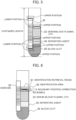
- the boundary position correcting unit 14 uses an identifier (including a feature extractor B) formed of a network (such as, e.g., Convolutional Neural Network) that identifies the boundaries of the inclusions (inclusions such as, e.g., the serum (blood plasma), separating agent, blood clot, and urine) in detail to identify the boundaries of each of the inclusions calculated by the inclusion determining unit 13 on the basis of Expressions (1) and (2), while moving on a per pixel basis in an identification area 62 within a retrieval range 61 as illustrated in Fig. 6 , and correct each of the boundary positions of the inclusion at a position where the identification result y has a largest value.
- a network such as, e.g., Convolutional Neural Network
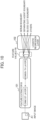
- FIG. 10 illustrates an example of obtention of the identification result.
- the input image A1 is input to a feature extractor B101, and feature values FBi are output.
- a logistic regression layer 102 identifies a boundary in the input image A1 on the basis of the feature values FBi.
- CNN represents Convolutional Neural Network.
- the boundary position correcting unit 14 reads, from the memory 90, the weight w, the filter coefficient wj, the offset values b and bi in Expressions (1) and (2) for identifying the boundaries of each of the inclusion, and calculates the identification result y of the likelihood of each of the boundaries. For example, the boundary position correcting unit 14 identifies the serum boundaries, while vertically moving on a per pixel basis in the identification area 62 within the retrieval range 61 around the serum boundaries, and corrects each of the boundary positions of the serum to a position where the identification result y is largest.
- the boundary position correcting unit 14 may also use an identifier (including a feature extractor C) formed of a network (such as, e.g., Convolutional Neural Network) that identifies an air bubble 63 for the boundary of the inclusion determined to be the serum upper portion by the inclusion determining unit 13 to identify the presence or absence of the air bubble in the identification area 62 on the basis of Expressions (1) and (2) and correct, when it is identified that there is the air bubble, the boundary position of the serum upper portion to a position of a lowermost end of the air bubble.
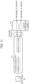
- Fig. 11 illustrates an example of obtention of the identification result.
- the input image A1 is input to a feature extractor C111, and feature values FCi are output therefrom.
- a logistic regression layer 112 determines the presence or absence of an air bubble in the input image A1 on the basis of the feature values FCi.
- CNN represents Convolutional Neural Network.
- the boundary position correction unit 14 reads, from the memory 90, the weight w, the filter coefficient wj, and the offset values b and bi in Expressions (1) and (2) for identifying the presence or absence of an air bubble, and calculates the identification result y of the air bubble 63.
- the boundary position correcting unit 14 stores, in the memory 90, each of the corrected boundary positions, the boundary positions of the barcode, the respective identification results thereof, and the identification result of the air bubble.
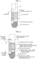
- the content calculating unit 15 uses the upper and lower boundary positions of each of the inclusions that have been corrected by the boundary position correcting unit 14 to calculate a content lv of each of the inclusions as illustrated in Fig. 7 .
- the content calculating unit 15 reads, from the memory 90, content information of a height from the container bottom and an area inside the container at the height, which is included in the information on the container type identified by the container identifying unit 11, and adds up individual contents from a height of the serum upper portion to a height of the serum lower portion to calculate the content lv of the serum 33.
- the content calculating unit 15 calculates a distance ds from a position of the container upper portion calculated by the container identifying unit 11 to the boundary of the serum upper portion.
- the content calculating unit 15 may also, e.g., correct pixel information (x1, y1) of each of the boundary positions of the serum upper portion and the serum lower portion to (x3, y3) by using Expression (3) to Expression (8), and then calculate the content lv of the serum.
- x, y in Expression (3) represent a point including distortion on camera coordinates
- x1, y1 therein represent a point including distortion on image coordinates
- cx, cy therein represent an image center
- fx, fy therein represent a focal length
- k1, k2 in Expression (5) represent a distortion coefficient in a radial direction
- p1, p2 in Expression (6) represent a distortion coefficient in a circumferential direction
- x2, y2 in Expression (7) represent a point obtained by correcting distortion on the camera coordinates
- x3, y3 in Expression (8) represent a point obtained by correcting distortion on the image coordinates.
- the content calculating unit 15 stores, in the memory 90, the content lv and the distance ds each calculated thereby.
- the sample condition assessing unit 16 uses the boundary position detection result lr calculated by the boundary position detecting unit 12, the determination results pr of the individual boundaries calculated by the inclusion determining unit 13, and the content lv calculated by the content calculating unit 15 to assess whether or not the target container is testable.
- Fig. 13 illustrates a flow chart of the sample condition assessing unit 16.
- the sample condition assessing unit 16 assesses that the target container is an empty container when, e.g., the boundary position detection result lr is 0, and sets 0 (untestable) to the testability assessment result, while setting the empty container to a testability assessment reason.
- the sample condition assessing unit 16 sets 0 (untestable) to the testability assessment result, while setting "Insufficient Content" to the testability assessment reason.
- the sample condition assessing unit 16 sets 0 (untestable) to the testability assessment result, while setting "Serum is absent" to the testability assessment reason.
- the boundary position detection result lr is equal to or more than 1
- the content lv is equal to or more than the threshold TH
- the boundary determination results pr include p3 and p4 or p3 and p9
- the sample condition assessing unit 16 sets 1 (testable) to the testability assessment result iajr, while setting "Serum is present" to the testability assessment reason.
- the sample condition assessing unit 16 determines whether or not the boundary position detection result lr is 0. When lr is other than 0, processing moves to Step 1302. When lr is 0, the processing moves to Step 1307.
- the sample condition assessing unit 16 assesses whether or not the content lv calculated by the content calculating unit 15 is equal to or more than the threshold TH (e.g., 4 ⁇ l). When the content lv is equal to or more than the threshold TH, the processing moves to Step 1303. When the content lv is less than the threshold TH, the processing moves to Step 1307.
- the threshold TH e.g. 4 ⁇ l
- the sample condition assessing unit 16 assesses whether or not the determination results pr of the individual boundaries calculated by the inclusion determining unit 13 include p3. When the determination results pr of the individual boundaries include p3, the processing moves to Step 1304. When the determination results pr of the individual boundaries do not include p3, the processing moves to Step 1307.
- the sample condition assessing unit 16 assesses whether or not the determination results pr of the individual boundaries calculated by the inclusion determining unit 13 include p4. When the determination results pr of the individual boundaries include p4, the processing moves to Step 1305. When the determination results pr of the individual boundaries do not include p4, the processing moves to Step 1306.
- the sample condition assessing unit 16 sets 1 (testable) to the testability assessment result iajr.
- the sample condition assessing unit 16 assesses whether or not the determination results pr of the individual boundaries calculated by the inclusion determining unit 13 include p9. When the determination results pr of the individual boundaries include p9, the processing moves to Step 1305. When the determination results pr of the individual boundaries do not include p9, the processing moves to Step 1307.
- the sample condition assessing unit 16 sets 0 (untestable) to the testability assessment result iajr.
- the sample condition assessing unit 16 stores, in the memory 90, the calculated testability assessment result iajr and the testability assessment reason.
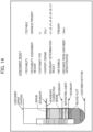
- the output unit 17 displays, on a GUI (graphical user interface) illustrated in Fig. 14 , the container type ct calculated by the container identifying unit 11, a line of each of the boundaries detected by the boundary position detecting unit 12, the identification result of the upper region and the lower region of each of the boundaries and the boundary determination result each resulting from the determination made by the inclusion determining unit 13, a line (e.g., boundary (corrected)) of each of the boundaries corrected by the boundary position correcting unit 14, the content lv and the distance ds of each of the inclusions that are calculated by the content calculating unit 15, and the result of the assessment of the testability of the target container made by the sample condition assessing unit 16 and the assessment reason.
- a GUI graphical user interface
- Fig. 14 is a diagram illustrating an example of a case where the target container contains the serum, the separating agent, and the blood clot and the boundary position of the serum is corrected.
- the testability of the target container is "Testable”
- the testability assessment reason is "Serum is present”
- the container type is "A”
- the content (serum) is 20 ⁇ l
- the boundary determination results are p1, p2, p3, p4, p5, p6, p8, and p11
- the identification result of the air bubble is "Present”
- the distance from the upper portion of the container is 18 mm
- the upper boundary line of the serum, the corrected upper boundary line of the serum, the lower boundary line of the serum (the upper boundary line of the separating agent), the lower boundary line of the separating agent (upper boundary line of the blood clot), and the boundary line of the container bottom are displayed.
- the output unit 17 is not an essential component of the specimen condition assessing device 1 and, in a case where the output unit is included in the sample testing device, the specimen condition assessing device 1 need not hold the output unit 17.
- Fig. 15 is a flow chart for illustrating an operation of the specimen condition assessing device 1 according to the embodiment of the present invention.
- each of the processing units (such as the input unit 10 and the inclusion determining unit 13) is described as an operating entity, but it may also be read such that the CPU 201 serves as the operating entity and implements each of the processing units as a program.
- the input unit 10 receives a target image and outputs the input image to the container identifying unit 11.
- the container identifying unit 11 uses the container detector to detect the container from the input image, further identifies the container type ct, detects respective positions of the container upper portion and the container bottom, and stores the obtained information in the memory 90.
- the boundary position detecting unit 12 uses the boundary position detector to detect each of boundary positions (such as the boundaries of the inclusions) and the barcode boundaries in the container and stores the obtained information in the memory 90.
- the inclusion determining unit 13 calculates the identification result of the upper regions and the lower regions of each of the boundary positions and the barcode boundaries and the determination results pr of the individual boundaries on the basis of Expression (1) and Expression (2), and stores the obtained information in the memory 90.
- the boundary position correction unit 14 obtains each of the corrected boundary positions, the boundary positions of the barcode, the respective identification results thereof, and the identification result of the air bubble on the basis of Expression (1) and Expression (2), and stores the obtained information in the memory 90.
- the content calculating unit 15 uses information on the position of the container upper portion and the upper and lower boundary positions of each of the inclusions to obtain the content lv of each of the inclusions and the distance ds from the container upper portion to the serum upper portion, and stores the obtained information in the memory 90. In addition, the content calculating unit 15 corrects the information on each of the boundary positions, obtains the content lv of each of the inclusions and the distance ds from the container upper portion to the serum upper position from the corrected information on each of the boundary positions on the basis of Expression (3) to Expression (8), and stores each content lv and the distance ds in the memory 90.
- the sample condition assessing unit 16 uses the boundary position detection result lr calculated by the boundary position detecting unit 12, the determination results pr of the individual boundaries calculated by the inclusion determining unit 13, and the content lv calculated by the content calculating unit 15 to assess whether or not the target container is testable, and stores the calculated testability assessment result iajr in the memory 90.
- the first embodiment by identifying the container type, detecting each of the boundary positions in the container and the barcode boundary positions, calculating the identification result of the upper and lower regions of each of the boundary positions in the container and the barcode, identifying the periphery of each of the boundary positions in detail to correct the boundary position, calculating the content of the target inclusion in the container, and further assessing the condition of the sample in the container by using the calculated content and the identification result of the peripheral region of each of the boundary positions, it is possible to detect the content of the inclusion in the container from the image with high precision and precisely assess whether or not the target container is testable.
- Fig. 16 is a functional block diagram illustrating a configuration of a sample testing device 1600 according to a second embodiment of the present invention.
- the sample testing device 1600 includes the specimen condition assessing device 1 according to the first embodiment, a sample sucking device 1601, and a display device 1602.
- the sample sucking device 1601 has a device that controls, e.g., a sample sampling mechanism including a suction nozzle and uses the sucked sample and a reagent to calculate a result of analyzing testing items related to the sample (such as, e.g., HbA1c, TP, and AST related to biochemical analysis and immunity analysis).
- a sample sampling mechanism including a suction nozzle
- a reagent to calculate a result of analyzing testing items related to the sample (such as, e.g., HbA1c, TP, and AST related to biochemical analysis and immunity analysis).
- the sample sucking device 1601 receives testability information (such as the testability assessment result iajr) from the specimen condition assessing device 1, and controls the sample sampling mechanism when the testability assessment result iajr is 1 (testable) to suck a portion of the sample and calculate the analysis result of each of the testing items by using the reagent.
- the display device 1602 displays the analysis result on a display screen. Meanwhile, when the testability assessment result iajr is 0 (untestable), the sample sampling mechanism does not suck the sample, and the display device 1602 displays "Untestable" with respect to the testability on the display screen.
- the sample sucking device 1601 receives, from the specimen condition assessing device 1, information on the distance ds from the container upper portion and controls a sucking position of the suction nozzle of the sample sampling mechanism.
- sample sucking device 1601 a biochemical analytical device, an immunity analytical device, or the like including the sample sampling mechanism may also be used.
- the second embodiment it is possible to provide a sample testing device that causes the sample sucking device to control whether or not the sample can be sucked with high precision by using the testability information assessed by the specimen condition assessing device and analyze each of the testing items related to the sample by using the sucked sample and the reagent and causes the display device to display the analysis result of each of the testing items to thereby allow efficient testing to be performed and allow an amount of the sample collected from a patient to be reduced to an extremely small amount.
- each of the container identifying unit 11 and the boundary position detecting unit 12 uses the YOLO as the container detector or the boundary position detector to detect the container or the boundary position
- SSD Single Shot MultiBox Detector
- R-CNN R-CNN
- Fast R-CNN Faster R-CNN, or the like may also be used to achieve the same effect.
- the present invention can also be implemented by a program code of software that implements the functions of the embodiments.
- a storage medium with the program code recorded thereon is provided to a system or a device, and a computer (or a CPU or MPU) in the system or device reads the program code stored in the storage medium.
- the program code read from the storage medium implements the functions of the embodiments previously described, and the program code and the storage medium with the program code stored thereon form the present invention.
- a flexible disk, CD-ROM, DVD-ROM, a hard disk, an optical disc, a magneto-optical disk, CD-R, a magnetic tape, a nonvolatile memory card, ROM, or the like is used as the storage medium for providing such a program code.
- a flexible disk, CD-ROM, DVD-ROM, a hard disk, an optical disc, a magneto-optical disk, CD-R, a magnetic tape, a nonvolatile memory card, ROM, or the like is used as the storage medium for providing such a program code.
- an OS operating system
- the CPU or the like of the computer may perform, on the basis of the instruction of the program code, a part or the whole of actual processing, and the functions of the embodiments previously described may also be implemented by the processing.
- the program code of the software that implements the functions of the embodiments may be distributed via a network to be stored in a storage means such as a hard disk or memory in the system or device or in a storage medium such as CD-RW or CD-R and, at the time of use, the computer (or the CPU or MPU) in the system or the device may also read the program code stored in the storage means or the storage medium and execute the program code.
- a storage means such as a hard disk or memory in the system or device or in a storage medium such as CD-RW or CD-R
- control lines and information lines represent those that are considered to be necessary for description purposes, and do not necessarily represent all control lines and information lines that are necessary for a product. It may also be possible that all configurations are mutually connected.
Landscapes
- Engineering & Computer Science (AREA)
- Health & Medical Sciences (AREA)
- Life Sciences & Earth Sciences (AREA)
- Physics & Mathematics (AREA)
- General Physics & Mathematics (AREA)
- Chemical & Material Sciences (AREA)
- General Health & Medical Sciences (AREA)
- Biochemistry (AREA)
- Analytical Chemistry (AREA)
- Pathology (AREA)
- Immunology (AREA)
- Biomedical Technology (AREA)
- Theoretical Computer Science (AREA)
- Hematology (AREA)
- Computer Vision & Pattern Recognition (AREA)
- Molecular Biology (AREA)
- Biophysics (AREA)
- Medicinal Chemistry (AREA)
- Food Science & Technology (AREA)
- Urology & Nephrology (AREA)
- Multimedia (AREA)
- Dispersion Chemistry (AREA)
- Quality & Reliability (AREA)
- Ecology (AREA)
- Investigating Or Analysing Biological Materials (AREA)
- Investigating Materials By The Use Of Optical Means Adapted For Particular Applications (AREA)
- Image Analysis (AREA)
Abstract
Description
- The present application claims priority from
Japanese Patent Application No. 2022-101278 filed on Jun. 23, 2022 - The present invention relates to a specimen condition assessing device, a specimen condition assessing method, and a specimen testing device, and relates to an image processing technology using machine learning which is for, e.g., detecting and identifying a specific inclusion in a specimen (such as, e.g., a serum (blood plasma)) included in a photographed image.
- In recent years, the importance of blood testing has been growing and, in blood analysis also, the number of tests and the number of testing items have increased, and improved testing efficiency is required. To improve the testing efficiency, there is an increasing need to detect a precise content of a serum or the like or assess a testable sample container before testing. To detect a content of serum or the like, there are technologies proposed in, e.g.,
Japanese Unexamined Patent Application Publication No. Hei10(1998)-232228 Japanese Unexamined Patent Application Publication No. Hei09(1997)-133687 Japanese Unexamined Patent Application Publication No. 2005-265813 Japanese Unexamined Patent Application Publication No. Hei10(1998)-232228 Japanese Unexamined Patent Application Publication No. Hei09(1997)-133687 Japanese Unexamined Patent Application Publication No. 2005-265813 - However, air bubbles may occasionally be generated on a sample to result in a problem that, even when the plurality of color extraction means in
Japanese Unexamined Patent Application Publication No. Hei10(1998)-232228 Japanese Unexamined Patent Application Publication No. Hei09(1997)-133687 Japanese Unexamined Patent Application Publication No. 2005-265813 Japanese Unexamined Patent Application Publication No. Hei10(1998)-232228 Japanese Unexamined Patent Application Publication No. Hei09(1997)-133687 Japanese Unexamined Patent Application Publication No. 2005-265813 - The present invention has been achieved in view of such circumstances and provides a technology that allows boundary positions of a serum (blood plasma) or the like in an image to be detected and allows whether or not a specimen container is testable to be precisely assessed.
- A specimen condition assessing device according to an aspect of the present invention includes a processor that executes a program for performing image processing on an image of a target specimen container and a memory for storing a result of the image processing. The processor performs processing of inputting the image, processing of detecting one or more boundary position from the image, processing of determining a property (type) of upper and lower regions of each of the one or more boundary positions and determining a boundary position of each inclusion, and processing of assessing whether or not the target specimen container is testable on the basis of the determined boundary position of each inclusion.
- Further features related to the present invention will be made apparent from the statement in this description and the accompanying drawings. The aspect of the present invention is attained and implemented by elements, a combination of various elements, the following detailed statement, and a form of the appended claims.
- It is necessary to understand that the statement in this description is merely a typical illustration and by no means limits the claims or application examples of the present invention.
- According to the aspect of the present invention, it is possible to detect a boundary position in an image and precisely assess whether or not a specimen container is testable.
-
-
Fig. 1 is a block diagram illustrating functions of a specimen condition assessing device according to a first embodiment. -
Fig. 2 is a diagram illustrating an example of a hardware configuration of the specimen condition assessing device according to the first embodiment. -
Fig. 3 is a diagram for illustrating an example of an operation of a container identifying unit. -
Fig. 4 is a diagram for illustrating an example of an operation of a boundary position detecting unit. -
Fig. 5 is a diagram for illustrating an example of an operation of an inclusion determining unit. -
Fig. 6 is a diagram for illustrating an example of an operation of a boundary position correcting unit. -
Fig. 7 is a diagram for illustrating an example of an operation of a content calculating unit. -
Fig. 8 is a diagram for illustrating an example of the operation of the inclusion determining unit. -
Fig. 9 is a diagram for illustrating an example of identification of upper and lower regions of each boundary by the inclusion determining unit. -
Fig. 10 is a diagram for illustrating an example of identification of each boundary by the boundary position correcting unit. -
Fig. 11 is a diagram for illustrating an example of identification of air bubbles by the boundary position correcting unit. -
Fig. 12 is a diagram for illustrating an example of an operation of the content calculating unit. -
Fig. 13 is a diagram for illustrating an example of an operation of a sample condition assessing unit. -
Fig. 14 is a diagram for illustrating an example of display of a determination result or the like from an output unit. -
Fig. 15 is a flow chart for illustrating an overall operation of a specimencondition assessing device 1 according to the first embodiment. -
Fig. 16 is a diagram illustrating a schematic configuration of a sample testing device according to a second embodiment in which the specimen condition assessing device in the embodiment is mounted. - An embodiment of the present description provides a specimen condition assessing device and a specimen condition assessing method that detect boundary positions of a plurality of inclusions, while determining a type (property) of each of the inclusions around each of the boundary positions, further calculate a content thereof, while correcting the boundary position, and determine the presence or absence of each of the inclusions (such as, e.g., a serum (blood plasma), a separating agent, a blood clot, and urine) of a sample in a container on the basis of the plurality of boundary positions and a result of the determination of the inclusion to thereby implement high-precision determination of the content of each of the inclusions (such as, e.g., the serum (blood plasma), separating agent, blood clot, and urine) and assessment of whether or not a target sample container is testable.
- Referring to the accompanying drawings, a description will be given below of embodiments of the present invention. In the drawings, functionally identical elements may be represented by the same numerals. Note that the accompanying drawings illustrate specific embodiments and implementation examples based on a principle of the present invention, but these are provided to allow the present invention to be understood and should not be used to limitatively construe the present invention.
- While sufficiently detailed description for a person skilled in the art to implement the present invention is made in this embodiment, other implementations and modes are also possible, and it is necessary to understand that configurations/structures can be changed and various elements can be replaced without departing from the scope and spirit of the technical idea of the present invention. Therefore, the following description should not be construed as being limited to this.
- Furthermore, as will be described later, each of the embodiments of the present invention may also be implemented using software operating on a versatile computer or may also be implemented using dedicated hardware or a combination of software and hardware.
- The following will describe each processing in the embodiments of the present invention by using "Each of processing units (such as, e.g., an inclusion determining unit) as a program" as a subject (operating entity) but, since the program performs determined processing while using a memory and a communication port (communication control device) by being executed by a processor (such as a CPU), the description may also be given by using the processor as the subject.
- A specimen condition assessing device in one of the embodiments of the present description may also include a function of detecting a boundary position in a container and determining an inclusion and a function of assessing a condition of a specimen container. The specimen container is a combination of a container and a specimen contained in the container. The specimen condition assessing device may further include a function of correcting the boundary position. The embodiment in the present description detects the boundary position even when there is an air bubble or the like in the vicinity of the boundary position, determines the inclusions, the air bubble, and the like around the boundary position, analyzes the likelihood of a boundary around the boundary position in detail, and corrects the boundary position. This allows the boundary position of a serum (blood plasma) or the like in an image and a content thereof to be determined with high precision. By additionally determining the presence or absence of each of inclusions (such as a serum (blood plasma), a separating agent, a blood clot, and urine) in the container on the basis of a plurality of the boundary positions and the result of determining the inclusion, it is possible to assess whether or not the target sample container is testable.
-
Fig. 1 is a block diagram illustrating a functional configuration of a specimen condition assessing device according to the embodiment. The specimencondition assessing device 1 includes aninput unit 10, acontainer identifying unit 11, a boundaryposition detecting unit 12, aninclusion determining unit 13, a boundaryposition correcting unit 14, acontent calculating unit 15, a samplecondition assessing unit 16, acontrol unit 19, and amemory 90. Note that, in the specimen condition assessing device, when container information has been given in advance, thecontainer identifying unit 11 is not an essential component. The specimencondition assessing device 1 may also be mounted in a sample testing device, as will be described later (second embodiment). The embodiments described hereinbelow are applicable also to a specimen different from a sample collected from a human. - In the specimen
condition assessing device 1, thecontainer identifying unit 11, the boundaryposition detecting unit 12, theinclusion determining unit 13, the boundaryposition correcting unit 14, thecontent calculating unit 15, and the samplecondition assessing unit 16 may be implemented by programs or may also be implemented by being modularized. - To the
input unit 10, image data is input. For example, theinput unit 10 may acquire encoded still image data in a JPG, Jpeg 2000, PNG, BMP, or like format resulting from image capturing performed at predetermined time intervals by an image capturing means, such as a camera built in an image acquiring device, and use an image thereof as an input image. Alternatively, theinput unit 10 may also extract the still image data of frames at predetermined intervals from dynamic image data in a Motion JPEG, MPEG, H. 264, HD/SDI, or like format, and use an image thereof as the input image. Still alternatively, theinput unit 10 may also use an image acquired by the image capturing means via a bus, a network, or the like as the input image. Yet alternatively, theinput unit 10 may also use an image already stored in a detachable recording medium as the input image. The image input from theinput unit 10 is output via thememory 90 to thecontainer identifying unit 11, the boundaryposition detecting unit 12, theinclusion determining unit 13, and the boundaryposition correcting unit 14. - The
container identifying unit 11 uses a network that detects the entire container or a portion of the container (e.g., a container detector such as YOLO) to detect the container from the input image and identify the input image. In addition, thecontainer identifying unit 11 stores the calculated container information in thememory 90. - The boundary
position detecting unit 12 uses a network that detects each boundary position and barcode boundaries (e.g., a boundary position detector such as YOLO) to detect each boundary position and the barcode boundaries from the input image. The boundary position is an interface between individual inclusions or between each inclusion and another substance. The barcode represents, e.g., information on a sample or a patient from which the sample has been collected. The boundaryposition detecting unit 12 stores, in thememory 90, calculated information such as each boundary position and the barcode boundaries. - The
inclusion determining unit 13 uses an identifier formed of a network (such as, e.g., Convolutional Neural Network) that identifies inclusions (such as, e.g., a serum (blood plasma), a separating agent, a blood clot, and urine) in upper and lower regions of each boundary position and the barcode each detected by the boundaryposition detecting unit 12, an object other than the inclusions (such as, e.g., background), and the barcode to calculate an identification result of the upper and lower regions of each boundary position and the barcode. In addition, theinclusion determining unit 13 stores, in thememory 90, information such as the calculated identification result of the upper and lower regions of each boundary position and the barcode. - The boundary
position correcting unit 14 uses an identifier formed of a network (such as, e.g., Convolutional Neural Network) that identifies each boundary position in detail to identify a periphery of each boundary position detected by the boundaryposition detecting unit 12 in detail, detect a precise boundary position, and correct the boundary position. In addition, the boundaryposition correcting unit 14 uses an identifier formed of a network (such as, e.g., Convolutional Neural Network) that identifies the presence or absence of a bubble around each boundary position to identify the presence or absence of a bubble and correct, when there is a bubble, the boundary position to a lowermost end of the bubble. In addition, the boundaryposition correcting unit 14 stores, in thememory 90, information such as each corrected boundary position. - The
content calculating unit 15 calculates a content of the target inclusion (such as, e.g., the serum (blood plasma), separating agent, blood clot, or urine) in the container from each boundary position corrected by the boundaryposition correcting unit 14 and container information or container information identified by thecontainer identifying unit 11. In addition, thecontent calculating unit 15 stores, in thememory 90, information such as the calculated content of each of the inclusions in the container. - The sample
condition assessing unit 16 uses the content calculated by thecontent calculating unit 15 or the identification result of the individual regions obtained by theinclusion determining unit 13 to assess whether or not the target sample container (container containing a sample) is testable. In addition, the samplecondition assessing unit 16 stores, in thememory 90, information such as a result of assessing whether or not the target container is testable. - The
control unit 19 is implemented by a processor and connected to each of elements in the specimencondition assessing device 1. An operation of each of the elements of the specimencondition assessing device 1 is implemented by an autonomous operation of each of the components described above or according to an instruction from thecontrol unit 19. - Thus, in the specimen
condition assessing device 1 in the present embodiment, thecontainer identifying unit 11 identifies a type of the container. The boundaryposition detecting unit 12 detects each boundary position in the container and the barcode boundary positions. Theinclusion determining unit 13 calculates the identification result of the upper and lower regions of each boundary position in the container and the barcode. The boundaryposition correcting unit 14 identifies the periphery of each boundary position in detail to correct the boundary position, while thecontent calculating unit 15 calculates the content of the target inclusion in the container. The samplecondition assessing unit 16 uses the calculated content and the identification result of the peripheral regions of each boundary position to assess a condition of a sample in the container, thereby detect the content of the inclusion in the container from the image with high precision, and assess whether or not the target container is testable. -
Fig. 2 is a diagram illustrating an example of a hardware configuration of the specimencondition assessing device 1 according to the embodiment of the present invention. - The specimen
condition assessing device 1 includes a CPU (processor) 201 that executes various programs, amemory 202 that stores the various programs, a storage device (corresponding to the memory 90) 203 that stores various data, anoutput device 204 for outputting each boundary position, each content, the result of assessing whether or not the target container is testable, and the like, and aninput device 205 for inputting an instruction from a user, an image, and the like, which are connected to each other via abus 207. - The
CPU 201 reads the various programs from thememory 202 as necessary, and executes the programs. Thememory 202 stores theinput unit 10, thecontainer identifying unit 11, the boundaryposition detecting unit 12, theinclusion determining unit 13, the boundaryposition correcting unit 14, thecontent calculating unit 15, and the samplecondition assessing unit 16 each as the program. - The
storage device 203 stores the input image, information on the type of the container identified by thecontainer identifying unit 11, information on each boundary position in the container and the barcode boundary positions each detected by the boundaryposition detecting unit 12, the identification result of the upper and lower regions of each boundary position in the container and the barcode that is determined by theinclusion determining unit 13, information on the boundary position corrected by the boundaryposition correcting unit 14, information on the content of the target inclusion in the container calculated by thecontent calculating unit 15, the result of the assessment of whether or not the target container is testable performed by the samplecondition assessing unit 16, and the like. - The
output device 204 is configured to include devices such as a display, a printer, and a speaker. For example, theoutput device 204 displays, on a display screen, data generated by thecontainer identifying unit 11, the boundaryposition detecting unit 12, theinclusion determining unit 13, the boundaryposition correcting unit 14, thecontent calculating unit 15, and the samplecondition assessing unit 16. - The
input device 205 is configured to include devices such as a keyboard, a mouse, and a microphone. By theinput device 205, instructions (including determination of the inputting of the input image) from the user are input to the specimencondition assessing device 1. - The specimen condition determining device of the present invention identifies the container type, detects each boundary position in the container and the barcode boundary positions, calculates the identification result of the upper and lower regions of each boundary position in the container and the barcode, identifies the periphery of each boundary position in detail to correct the boundary position, calculates the content of the target inclusion in the container, and further assesses the condition of the sample in the container by using the calculated content and the identification result of the peripheral regions of each boundary position to thereby precisely assessing whether or not the target container is testable, while detecting the content of the inclusion in the container from the image with high precision.
- Hereinbelow, a detailed description will be given of a configuration and an operation of each of the elements.
-
Fig. 3 illustrates an example of the container. Thecontainer identifying unit 11 uses a network (a container detector such as, e.g., YOLO) that detects the entire container or a portion of the container to detect and identify the container from the input image, and determine a container type ct and a position of a containerupper portion 31, while calculating a position of a container bottom 36 in the image, which is illustrated inFig. 3 , from the calculated container type ct and container information in thememory 90. Thecontainer identifying unit 11 stores, in thememory 90, information on the identified container type and the respective positions of the container upper portion and the container bottom in the image. - The boundary
position detecting unit 12 detects the boundary positions (interfaces or boundaries) of the individual inclusions in the container and the barcode boundaries.Fig. 3 illustrates abarcode 32, aserum 33, a separatingagent 34, and ablood clot 35.Fig. 4 illustrates an example of boundary position detection. The boundaryposition detecting unit 12 uses a network (such as a boundary position detector such as, e.g., YOLO) that detects each of the boundary positions (such as the boundaries of the inclusions) in the container and the barcode boundaries to detect each of the boundary positions and the boundaries of thebarcode 32 from the input image as illustrated inFig. 4 . In the example illustrated inFig. 4 , aboundary 41 between the serum (blood plasma) 33 and the background, aboundary 42 between theserum 33 and the separatingagent 34, and aboundary 43 between the blood clot and the separating agent are detected. In addition, anupper boundary 44 and alower boundary 45 of thebarcode 32 are detected. - When none of boundaries such as the boundary positions can be detected, the boundary
position detecting unit 12sets 0 to a boundary position detection result lr and stores the boundary position detection result lr in the memory. When detecting one or more boundaries such as the boundary positions, the boundaryposition detecting unit 12 sets the number of the detected boundaries to the boundary position detection result lr. The boundaryposition detecting unit 12 stores, in thememory 90, the calculated boundary position detection results lr and information on each of the detected boundary positions. - As illustrated in
Fig. 5 , theinclusion determining unit 13 uses an identifier formed of a network (such as, e.g., Convolutional Neural Network) that identifies inclusions (inclusions such as, e.g., the serum (blood plasma), separating agent, blood clod, and urine) and objects other than the inclusions (such as, e.g., the background and the barcode) to calculate, for the upper and lower regions of each of the boundary positions and the barcode each detected by the boundaryposition detecting unit 12, the identification result of the upper and lower regions of each boundary position and the barcode. When containers include containers made of various materials such as a transparent-type container and an opaque-type container, theinclusion determining unit 13 uses information on the container type identified by thecontainer identifying unit 11 to select an identifier appropriate for the container, and uses the selected identifier to calculate the identification result of the upper and lower regions of each boundary position and the barcode. - By way of example,
Fig. 9 illustrates an example of obtention of the identification result. An input image A1 is input to a feature extractor A91, and feature values FAi are output therefrom. Alogistic regression layer 92 identifies a region in the input image A1 on the basis of the feature values FAi. InFig. 9 , CNN represents Convolutional Neural Network. - The
inclusion determining unit 13 reads, from thememory 90, a weight w, a filter coefficient wj, and offset values b and bi in Expressions (1) and (2). - For example, using the feature extractor A91, for the upper and lower regions of each of boundary positions and the barcode in the input image A1, the feature values FAi of the inclusions (inclusions such as, e.g., the serum (blood plasma), separating agent, blood clot, and urine) and objects other than the inclusions (such as, e.g., the background and the barcode) are obtained on the basis of Expression (1).
- The filter coefficient wj shown in Expression (1) is a coefficient determined by machine learning or the like so as to identify each of the inclusions (such as, e.g., the serum (blood plasma), separating agent, blood clot, and urine) as such and so as to identify each of the objects other than the inclusions (such as, e.g., the background and barcode) as such.
- In Expression (1), pj represents a pixel value, bi represents an offset value, m represents the number of filter coefficients, and h represents a non-linear function. Using Expression (1), for each of the regions of the target image from the upper left to the lower right, a calculation result of each of filters is obtained to obtain feature values fi of any filter i. For example, it is assumed that a matrix of the feature values fi obtained by the feature extractor A91 are the feature values FAi of the input image A1.
[Expression 1]
- As illustrated in
Fig. 9 , using the calculated feature values FAi (matrix f) from the feature extractor A91, thelogistic regression layer 92 of the identifier calculates a value of the likelihood of each of the inclusions and the objects other than the inclusions to be detected (such as the likelihood of the serum (blood plasma), the likelihood of the separating agent, the likelihood of the blood clot, the likelihood of the background, and the likelihood of the barcode) on the basis of Expression (2) to determine whether or not each of the regions in the input image A1 (e.g., the upper and lower regions of the boundary positions) is the inclusion to be detected (such as, e.g., the serum (blood plasma), separating agent, blood clot, or urine) or the object other than the inclusions to be detected (such as, e.g., the background or the barcode). - In Expression (2), w represents a weight matrix, b represents an offset value, g represents a non-linear function, and y represents an identification result and, by using a known machine learning technology, the weight w and the offset value b are determined in advance by using training images. For example, as the machine learning technology, Convolutional Neural Network may also be used. In addition, by using the weight w and the offset value b which were obtained during leaning, each of the regions of the target image is identified, and an identification result y is calculated.
[Expression 2]
- The
inclusion determining unit 13 determines what each of the boundaries is on the basis of the identification result y of the upper region and the lower region of each of the boundary positions and the barcode boundaries each detected by the boundaryposition detecting unit 12. For example, as illustrated inFig. 8 , when the identification result of the upper region is the background and the identification result of the lower region is thebarcode 32, the boundary therebetween is determined to be the barcode upper portion 44 (p1 is set to the determination result pr). Meanwhile, when the identification result of the upper region is thebarcode 32 and the identification result of the lower region is any of theserum 33, theblood clot 35, the separatingagent 34, and the background, the boundary therebetween is determined to be the barcode lower portion 45 (p2 is set to the determination result pr). - Still alternatively, when the identification result of the upper region is the background and the identification result of the lower region is the
serum 33, theboundary 41 therebetween is determined to be a serum upper portion (p3 is set to the determination result pr). Yet alternatively, when the identification result of the upper region is theserum 33 and the identification result of the lower region is either of the separatingagent 34 and theblood clot 35, theboundary 42 therebetween is determined to be a serum lower portion (p4 is set to the determination result pr). Still alternatively, when the identification result of the upper region is the separatingagent 34 and the identification result of the lower region is either of theblood clot 35 and the container bottom, theboundary 43 therebetween is determined to a separating agent lower portion (p5 is set to the determination result pr). - Yet alternatively, when the identification result of the upper region is any of the separating
agent 34, theserum 33, and the background and the identification result of the lower region is theblood clot 35, theboundary 43 therebetween is determined to be a blood clot upper portion (p6 is set to the determination result pr). Still alternatively, when the identification result of the upper region is theblood clot 35 and the identification result of the lower region is the separatingagent 34, the boundary therebetween (not shown) is determined to be a blood clot lower portion (p7 is set to the determination result pr). Yet alternatively, when the identification result of the upper region of the container bottom is theblood clot 35, theboundary 44 thereof is determined to be the blood clot lower portion (p8 is set to the determination result pr). - Still alternatively, when the identification result of the upper region of the container bottom is the
serum 33, the boundary thereof (not shown) is determined to be the serum lower portion (p9 is set to the determination result pr). Yet alternatively, when the identification result of the upper region of the container bottom is the separatingagent 34, the boundary thereof (not shown) is determined to be the separating agent lower portion (p10 is set to the determination result pr). Still alternatively, when the identification result of the upper region is any of theserum 33, the background, and theblood clot 35 and the identification result of the lower region is the separatingagent 34, theboundary 42 therebetween is determined to be a separating agent upper portion (p11 is set to the determination result pr). For example, in a case ofFig. 5 , to the boundary determination results pr, p1, p2, p3, p4, p5, p6, p8, and p11 is set. - The
inclusion determining unit 13 excludes boundary candidates which are not the boundary positions and the barcode boundaries each detected by the boundaryposition detecting unit 12. - The
inclusion determining unit 13 stores, in thememory 90, the calculated identification result y and the individual boundary determination results pr. - The boundary
position correcting unit 14 uses an identifier (including a feature extractor B) formed of a network (such as, e.g., Convolutional Neural Network) that identifies the boundaries of the inclusions (inclusions such as, e.g., the serum (blood plasma), separating agent, blood clot, and urine) in detail to identify the boundaries of each of the inclusions calculated by theinclusion determining unit 13 on the basis of Expressions (1) and (2), while moving on a per pixel basis in anidentification area 62 within aretrieval range 61 as illustrated inFig. 6 , and correct each of the boundary positions of the inclusion at a position where the identification result y has a largest value. By way of example,Fig. 10 illustrates an example of obtention of the identification result. The input image A1 is input to a feature extractor B101, and feature values FBi are output. Alogistic regression layer 102 identifies a boundary in the input image A1 on the basis of the feature values FBi. InFig. 10 , CNN represents Convolutional Neural Network. - The boundary
position correcting unit 14 reads, from thememory 90, the weight w, the filter coefficient wj, the offset values b and bi in Expressions (1) and (2) for identifying the boundaries of each of the inclusion, and calculates the identification result y of the likelihood of each of the boundaries. For example, the boundaryposition correcting unit 14 identifies the serum boundaries, while vertically moving on a per pixel basis in theidentification area 62 within theretrieval range 61 around the serum boundaries, and corrects each of the boundary positions of the serum to a position where the identification result y is largest. - Alternatively, the boundary
position correcting unit 14 may also use an identifier (including a feature extractor C) formed of a network (such as, e.g., Convolutional Neural Network) that identifies anair bubble 63 for the boundary of the inclusion determined to be the serum upper portion by theinclusion determining unit 13 to identify the presence or absence of the air bubble in theidentification area 62 on the basis of Expressions (1) and (2) and correct, when it is identified that there is the air bubble, the boundary position of the serum upper portion to a position of a lowermost end of the air bubble. By way of example,Fig. 11 illustrates an example of obtention of the identification result. The input image A1 is input to a feature extractor C111, and feature values FCi are output therefrom. Alogistic regression layer 112 determines the presence or absence of an air bubble in the input image A1 on the basis of the feature values FCi. InFig. 11 , CNN represents Convolutional Neural Network. - The boundary
position correction unit 14 reads, from thememory 90, the weight w, the filter coefficient wj, and the offset values b and bi in Expressions (1) and (2) for identifying the presence or absence of an air bubble, and calculates the identification result y of theair bubble 63. - The boundary
position correcting unit 14 stores, in thememory 90, each of the corrected boundary positions, the boundary positions of the barcode, the respective identification results thereof, and the identification result of the air bubble. - The
content calculating unit 15 uses the upper and lower boundary positions of each of the inclusions that have been corrected by the boundaryposition correcting unit 14 to calculate a content lv of each of the inclusions as illustrated inFig. 7 . For example, thecontent calculating unit 15 reads, from thememory 90, content information of a height from the container bottom and an area inside the container at the height, which is included in the information on the container type identified by thecontainer identifying unit 11, and adds up individual contents from a height of the serum upper portion to a height of the serum lower portion to calculate the content lv of theserum 33. In addition, thecontent calculating unit 15 calculates a distance ds from a position of the container upper portion calculated by thecontainer identifying unit 11 to the boundary of the serum upper portion. - As illustrated in
Fig. 12 , depending on a viewpoint of a camera lens during photographing or the like, distortion may occur in pixel information as the viewpoint moves in an upward direction or a downward direction. Accordingly, thecontent calculating unit 15 may also, e.g., correct pixel information (x1, y1) of each of the boundary positions of the serum upper portion and the serum lower portion to (x3, y3) by using Expression (3) to Expression (8), and then calculate the content lv of the serum. Note that, x, y in Expression (3) represent a point including distortion on camera coordinates, x1, y1 therein represent a point including distortion on image coordinates, cx, cy therein represent an image center, and fx, fy therein represent a focal length, k1, k2 in Expression (5) represent a distortion coefficient in a radial direction, p1, p2 in Expression (6) represent a distortion coefficient in a circumferential direction, x2, y2 in Expression (7) represent a point obtained by correcting distortion on the camera coordinates, and x3, y3 in Expression (8) represent a point obtained by correcting distortion on the image coordinates.
[Expression 3]
[Expression 4]
[Expression 5]
[Expression 6]
[Expression 7]
[Expression 8]
- The
content calculating unit 15 stores, in thememory 90, the content lv and the distance ds each calculated thereby. - The sample
condition assessing unit 16 uses the boundary position detection result lr calculated by the boundaryposition detecting unit 12, the determination results pr of the individual boundaries calculated by theinclusion determining unit 13, and the content lv calculated by thecontent calculating unit 15 to assess whether or not the target container is testable.Fig. 13 illustrates a flow chart of the samplecondition assessing unit 16. - The sample
condition assessing unit 16, for example, assesses that the target container is an empty container when, e.g., the boundary position detection result lr is 0, and sets 0 (untestable) to the testability assessment result, while setting the empty container to a testability assessment reason. When the content lv is less than a threshold TH, the samplecondition assessing unit 16 sets 0 (untestable) to the testability assessment result, while setting "Insufficient Content" to the testability assessment reason. - When the boundary determination results pr do not include p3 and p4 or p3 and p9, the sample
condition assessing unit 16 sets 0 (untestable) to the testability assessment result, while setting "Serum is absent" to the testability assessment reason. When the boundary position detection result lr is equal to or more than 1, the content lv is equal to or more than the threshold TH, and the boundary determination results pr include p3 and p4 or p3 and p9, the samplecondition assessing unit 16 sets 1 (testable) to the testability assessment result iajr, while setting "Serum is present" to the testability assessment reason. - The sample
condition assessing unit 16 determines whether or not the boundary position detection result lr is 0. When lr is other than 0, processing moves to Step 1302. When lr is 0, the processing moves to Step 1307. - The sample
condition assessing unit 16 assesses whether or not the content lv calculated by thecontent calculating unit 15 is equal to or more than the threshold TH (e.g., 4µl). When the content lv is equal to or more than the threshold TH, the processing moves to Step 1303. When the content lv is less than the threshold TH, the processing moves to Step 1307. - The sample
condition assessing unit 16 assesses whether or not the determination results pr of the individual boundaries calculated by theinclusion determining unit 13 include p3. When the determination results pr of the individual boundaries include p3, the processing moves to Step 1304. When the determination results pr of the individual boundaries do not include p3, the processing moves to Step 1307. - The sample
condition assessing unit 16 assesses whether or not the determination results pr of the individual boundaries calculated by theinclusion determining unit 13 include p4. When the determination results pr of the individual boundaries include p4, the processing moves to Step 1305. When the determination results pr of the individual boundaries do not include p4, the processing moves to Step 1306. - The sample
condition assessing unit 16 sets 1 (testable) to the testability assessment result iajr. - The sample
condition assessing unit 16 assesses whether or not the determination results pr of the individual boundaries calculated by theinclusion determining unit 13 include p9. When the determination results pr of the individual boundaries include p9, the processing moves to Step 1305. When the determination results pr of the individual boundaries do not include p9, the processing moves to Step 1307. - The sample
condition assessing unit 16 sets 0 (untestable) to the testability assessment result iajr. - The sample
condition assessing unit 16 stores, in thememory 90, the calculated testability assessment result iajr and the testability assessment reason. - By way of example, the
output unit 17 displays, on a GUI (graphical user interface) illustrated inFig. 14 , the container type ct calculated by thecontainer identifying unit 11, a line of each of the boundaries detected by the boundaryposition detecting unit 12, the identification result of the upper region and the lower region of each of the boundaries and the boundary determination result each resulting from the determination made by theinclusion determining unit 13, a line (e.g., boundary (corrected)) of each of the boundaries corrected by the boundaryposition correcting unit 14, the content lv and the distance ds of each of the inclusions that are calculated by thecontent calculating unit 15, and the result of the assessment of the testability of the target container made by the samplecondition assessing unit 16 and the assessment reason. -
Fig. 14 is a diagram illustrating an example of a case where the target container contains the serum, the separating agent, and the blood clot and the boundary position of the serum is corrected. In the example illustrated inFig. 14 , the testability of the target container is "Testable", the testability assessment reason is "Serum is present", the container type is "A", the content (serum) is 20 µl, the boundary determination results are p1, p2, p3, p4, p5, p6, p8, and p11, the identification result of the air bubble is "Present", the distance from the upper portion of the container is 18 mm, and the upper boundary line of the serum, the corrected upper boundary line of the serum, the lower boundary line of the serum (the upper boundary line of the separating agent), the lower boundary line of the separating agent (upper boundary line of the blood clot), and the boundary line of the container bottom are displayed. - The
output unit 17 is not an essential component of the specimencondition assessing device 1 and, in a case where the output unit is included in the sample testing device, the specimencondition assessing device 1 need not hold theoutput unit 17. -
Fig. 15 is a flow chart for illustrating an operation of the specimencondition assessing device 1 according to the embodiment of the present invention. In the following, each of the processing units (such as theinput unit 10 and the inclusion determining unit 13) is described as an operating entity, but it may also be read such that theCPU 201 serves as the operating entity and implements each of the processing units as a program. - The
input unit 10 receives a target image and outputs the input image to thecontainer identifying unit 11. - The
container identifying unit 11 uses the container detector to detect the container from the input image, further identifies the container type ct, detects respective positions of the container upper portion and the container bottom, and stores the obtained information in thememory 90. - The boundary
position detecting unit 12 uses the boundary position detector to detect each of boundary positions (such as the boundaries of the inclusions) and the barcode boundaries in the container and stores the obtained information in thememory 90. - The
inclusion determining unit 13 calculates the identification result of the upper regions and the lower regions of each of the boundary positions and the barcode boundaries and the determination results pr of the individual boundaries on the basis of Expression (1) and Expression (2), and stores the obtained information in thememory 90. - The boundary
position correction unit 14 obtains each of the corrected boundary positions, the boundary positions of the barcode, the respective identification results thereof, and the identification result of the air bubble on the basis of Expression (1) and Expression (2), and stores the obtained information in thememory 90. - The
content calculating unit 15 uses information on the position of the container upper portion and the upper and lower boundary positions of each of the inclusions to obtain the content lv of each of the inclusions and the distance ds from the container upper portion to the serum upper portion, and stores the obtained information in thememory 90. In addition, thecontent calculating unit 15 corrects the information on each of the boundary positions, obtains the content lv of each of the inclusions and the distance ds from the container upper portion to the serum upper position from the corrected information on each of the boundary positions on the basis of Expression (3) to Expression (8), and stores each content lv and the distance ds in thememory 90. - The sample
condition assessing unit 16 uses the boundary position detection result lr calculated by the boundaryposition detecting unit 12, the determination results pr of the individual boundaries calculated by theinclusion determining unit 13, and the content lv calculated by thecontent calculating unit 15 to assess whether or not the target container is testable, and stores the calculated testability assessment result iajr in thememory 90. - According to the first embodiment, by identifying the container type, detecting each of the boundary positions in the container and the barcode boundary positions, calculating the identification result of the upper and lower regions of each of the boundary positions in the container and the barcode, identifying the periphery of each of the boundary positions in detail to correct the boundary position, calculating the content of the target inclusion in the container, and further assessing the condition of the sample in the container by using the calculated content and the identification result of the peripheral region of each of the boundary positions, it is possible to detect the content of the inclusion in the container from the image with high precision and precisely assess whether or not the target container is testable.
- In addition, by detecting the content of the inclusion in the container from the image with high precision, it is possible to reduce an amount of the sample collected from a patient to an extremely small amount.
-
Fig. 16 is a functional block diagram illustrating a configuration of asample testing device 1600 according to a second embodiment of the present invention. Thesample testing device 1600 includes the specimencondition assessing device 1 according to the first embodiment, asample sucking device 1601, and adisplay device 1602. - The
sample sucking device 1601 has a device that controls, e.g., a sample sampling mechanism including a suction nozzle and uses the sucked sample and a reagent to calculate a result of analyzing testing items related to the sample (such as, e.g., HbA1c, TP, and AST related to biochemical analysis and immunity analysis). - The
sample sucking device 1601 receives testability information (such as the testability assessment result iajr) from the specimencondition assessing device 1, and controls the sample sampling mechanism when the testability assessment result iajr is 1 (testable) to suck a portion of the sample and calculate the analysis result of each of the testing items by using the reagent. Thedisplay device 1602 displays the analysis result on a display screen. Meanwhile, when the testability assessment result iajr is 0 (untestable), the sample sampling mechanism does not suck the sample, and thedisplay device 1602 displays "Untestable" with respect to the testability on the display screen. In addition, thesample sucking device 1601 receives, from the specimencondition assessing device 1, information on the distance ds from the container upper portion and controls a sucking position of the suction nozzle of the sample sampling mechanism. - As the
sample sucking device 1601, a biochemical analytical device, an immunity analytical device, or the like including the sample sampling mechanism may also be used. - According to the second embodiment, it is possible to provide a sample testing device that causes the sample sucking device to control whether or not the sample can be sucked with high precision by using the testability information assessed by the specimen condition assessing device and analyze each of the testing items related to the sample by using the sucked sample and the reagent and causes the display device to display the analysis result of each of the testing items to thereby allow efficient testing to be performed and allow an amount of the sample collected from a patient to be reduced to an extremely small amount.
- Each of the embodiments described heretofore can be modified as follows. While the
inclusion determining unit 13 and the boundaryposition correcting unit 14 use filters to determine the plurality of feature values by machine learning, other feature values such as HOG may also be used to achieve the same effect. - While each of the
container identifying unit 11 and the boundaryposition detecting unit 12 uses the YOLO as the container detector or the boundary position detector to detect the container or the boundary position, SSD (Single Shot MultiBox Detector), R-CNN, Fast R-CNN, Faster R-CNN, or the like may also be used to achieve the same effect. - The present invention can also be implemented by a program code of software that implements the functions of the embodiments. In such a case, a storage medium with the program code recorded thereon is provided to a system or a device, and a computer (or a CPU or MPU) in the system or device reads the program code stored in the storage medium. In this case, the program code read from the storage medium implements the functions of the embodiments previously described, and the program code and the storage medium with the program code stored thereon form the present invention. As the storage medium for providing such a program code, for example, a flexible disk, CD-ROM, DVD-ROM, a hard disk, an optical disc, a magneto-optical disk, CD-R, a magnetic tape, a nonvolatile memory card, ROM, or the like is used.
- In addition, on the basis of an instruction of the program code, an OS (operating system) operating on the computer or the like may perform a part or the whole of actual processing, and the functions of the embodiments previously described may also be implemented by the processing. Moreover, after the program code read from the storage medium is written to a memory in the computer, the CPU or the like of the computer may perform, on the basis of the instruction of the program code, a part or the whole of actual processing, and the functions of the embodiments previously described may also be implemented by the processing.
- Furthermore, the program code of the software that implements the functions of the embodiments may be distributed via a network to be stored in a storage means such as a hard disk or memory in the system or device or in a storage medium such as CD-RW or CD-R and, at the time of use, the computer (or the CPU or MPU) in the system or the device may also read the program code stored in the storage means or the storage medium and execute the program code.
- Finally, it is to be appreciated that the process and technology described herein may be implemented by any appropriate combination of components without inherently being related to any specific device. Furthermore, various types of general-purpose devices can be used in accordance with the method described herein. It may be advantageous to build a dedicated device to execute the steps of the method described herein. In addition, various inventions can be formed by combining a plurality of components disclosed in the embodiments as appropriate. For example, some components may be removed from all the components shown in the embodiments. Moreover, the components in different embodiments may also be combined as appropriate. While the present invention has been described with reference to specific examples, such examples are shown not for limiting purposes but for description purposes in all aspects. Those skilled in the art may appreciate that there are a large number of combinations of hardware, software, and firmware that are appropriate for implementing the present invention. For example, the software described herein may be implemented by an assembler or a wide range of programs or script languages such as C/C++, perl, Shell, PHP, or Java (registered trademark).
- Furthermore, in the embodiments described above, the control lines and information lines represent those that are considered to be necessary for description purposes, and do not necessarily represent all control lines and information lines that are necessary for a product. It may also be possible that all configurations are mutually connected.
- In addition, other implementations of the present invention will become apparent to those having ordinary knowledge in this technical field from the examination of the description and the embodiments of the present invention disclosed herein. The various aspects and/or components of the embodiments described above can be used individually or in any combination thereof.
Claims (11)
- A specimen condition assessing device comprising:a processor that executes a program for performing image processing on an image of a target specimen container; anda memory for storing a result of the image processing,wherein the processor performs:processing of inputting an image;processing of detecting a boundary position from the image;processing of determining a type of upper and lower regions of each of the detected boundary position and determining a boundary position of each inclusion; andprocessing of assessing whether or not the target specimen container is testable on the basis of the determined boundary position of each inclusion.
- The specimen condition assessing device according to claim 1,
wherein the processor further performs:
processing of correcting each of the detected boundary position on the basis of the determined type of the upper and lower regions of each of the detected boundary position. - The specimen condition assessing device according to claim 1,
wherein the processor further performs:processing of identifying a container from the image to calculate container information;processing of selecting a detector according to the container information; andprocessing of determining the type of the upper and lower regions of each of the boundary position detected by using the selected detector and determining the boundary position of each inclusion andthe processor assesses whether or not the target specimen container is testable on the basis of the determined boundary position of each inclusion. - The specimen condition assessing device according to claim 1, 2, or 3,
wherein the processor further performs:processing of calculating a content on the basis of the determined boundary position of each inclusion andthe processor assesses whether or not the target specimen container is testable on the basis of the calculated content. - The specimen condition assessing device according to claim 2,
wherein the processor further performs:processing of identifying the container from the image and calculating container information; andprocessing of calculating a content on the basis of the container information and the determined boundary position of each inclusion andthe processor assesses whether or not the target specimen container is testable on the basis of the calculated content. - A specimen condition assessing method that assesses a condition of a target specimen container in an image, the specimen condition assessing method comprising:causing a processor that executes a program for performing image processing on an input image to input an image of the target specimen container;causing the processor to detect a boundary position from the image;causing the processor to determine a type of the upper and lower regions of each of the detected boundary position and determine a boundary position of each inclusion; andcausing the processor to assess whether or not the target specimen container is testable on the basis of the determined boundary position of each inclusion.
- The specimen condition assessing method according to claim 6, further comprising:
causing the processor to correct each of the detected boundary position on the basis of the determined type of the upper and lower regions of each of the detected boundary position. - The specimen condition assessing method according to claim 6, further comprising:causing the processor to identify the container from the image and calculate container information;causing the processor to select a detector according to the container information;causing the processor to determine the type of the upper and lower regions of each boundary position detected by using the selected detector and determine the boundary position of each inclusion; andcausing the processor to assess whether or not the target specimen container is testable on the basis of the determined boundary position of each inclusion.
- The specimen condition assessing method according to claim 6, 7, or 8, further comprising:causing the processor to calculate a content on the basis of the determined boundary position of each inclusion; andcausing the processor to assess whether or not the target specimen container is testable on the basis of the calculated content.
- The specimen condition assessing method according to claim 7, further comprising:causing the processor to identify the container from the image and calculate container information;causing the processor to calculate a content on the basis of the container information and the determined boundary position of each inclusion; andcausing the processor to assess whether or not the target specimen container is testable on the basis of the calculated content.
- A specimen testing device comprising:the specimen condition assessing device according to claim 1, 2, or 3;a specimen sucking device that controls whether or not to suck a specimen to analyze a testing item of the specimen; anda display device that displays a result of the analysis,wherein the specimen sucking device uses information on the testability assessed by the specimen condition assessing device to control whether or not to suck the specimen in the specimen container and uses the sucked specimen and a reagent to analyze the testing item related to the specimen andthe display device displays a result of the analysis of the testing item.
Applications Claiming Priority (2)
| Application Number | Priority Date | Filing Date | Title |
|---|---|---|---|
| JP2022101278A JP2024002211A (en) | 2022-06-23 | 2022-06-23 | Sample condition determination device, sample condition determination method, and sample inspection device |
| PCT/JP2023/021066 WO2023248789A1 (en) | 2022-06-23 | 2023-06-06 | Sample condition assessing device, sample condition assessing method, and sample testing device |
Publications (2)
| Publication Number | Publication Date |
|---|---|
| EP4545976A1 true EP4545976A1 (en) | 2025-04-30 |
| EP4545976A4 EP4545976A4 (en) | 2026-03-11 |
Family
ID=89379663
Family Applications (1)
| Application Number | Title | Priority Date | Filing Date |
|---|---|---|---|
| EP23826976.5A Pending EP4545976A4 (en) | 2022-06-23 | 2023-06-06 | DEVICE FOR ASSESSING SAMPLE CONDITION, METHOD FOR ASSESSING SAMPLE CONDITION AND SAMPLE TESTING DEVICE |
Country Status (4)
| Country | Link |
|---|---|
| EP (1) | EP4545976A4 (en) |
| JP (1) | JP2024002211A (en) |
| CN (1) | CN119317841A (en) |
| WO (1) | WO2023248789A1 (en) |
Families Citing this family (1)
| Publication number | Priority date | Publication date | Assignee | Title |
|---|---|---|---|---|
| JP2026021890A (en) * | 2024-07-30 | 2026-02-12 | 株式会社日立ハイテク | In-container sample state determination device, in-container sample state determination method, and sample analysis system |
Family Cites Families (12)
| Publication number | Priority date | Publication date | Assignee | Title |
|---|---|---|---|---|
| JPH09133687A (en) | 1995-11-13 | 1997-05-20 | Meiji Denki Kogyo Kk | Serum amount measuring device in blood sampling tube |
| JPH10232228A (en) | 1997-02-21 | 1998-09-02 | Matsushita Electric Ind Co Ltd | Blood test method and device |
| JPH1194840A (en) * | 1997-09-22 | 1999-04-09 | Hitachi Ltd | Transfer device |
| JP3858029B2 (en) | 2004-03-22 | 2006-12-13 | 株式会社アイディエス | Test tube detector |
| JP6422824B2 (en) * | 2015-05-29 | 2018-11-14 | 株式会社日立ハイテクノロジーズ | Sample pretreatment method and sample pretreatment apparatus |
| WO2017132167A1 (en) * | 2016-01-28 | 2017-08-03 | Siemens Healthcare Diagnostics Inc. | Methods and apparatus adapted to identify a specimen container from multiple lateral views |
| JP2018096740A (en) * | 2016-12-09 | 2018-06-21 | 株式会社日立ハイテクノロジーズ | Biological sample analyzer |
| US11815519B2 (en) * | 2017-07-19 | 2023-11-14 | Siemens Healthcare Diagnostics Inc. | Stray light compensating methods and apparatus for characterizing a specimen |
| EP3835737B1 (en) * | 2019-12-10 | 2024-03-20 | Roche Diagnostics GmbH | Method and apparatus for determining a vertical position of a horizontally extending interface between a first component and a second component |
| EP3885699A1 (en) * | 2020-03-27 | 2021-09-29 | Roche Diagnostics GmbH | System and method for processing a laboratory sample |
| JP7436270B2 (en) * | 2020-04-09 | 2024-02-21 | 株式会社日立ハイテク | Biospecimen analysis device |
| JP7539826B2 (en) | 2020-12-24 | 2024-08-26 | 川崎重工業株式会社 | Self-propelled robot and control method thereof |
-
2022
- 2022-06-23 JP JP2022101278A patent/JP2024002211A/en active Pending
-
2023
- 2023-06-06 CN CN202380045068.9A patent/CN119317841A/en active Pending
- 2023-06-06 WO PCT/JP2023/021066 patent/WO2023248789A1/en not_active Ceased
- 2023-06-06 EP EP23826976.5A patent/EP4545976A4/en active Pending
Also Published As
| Publication number | Publication date |
|---|---|
| CN119317841A (en) | 2025-01-14 |
| WO2023248789A1 (en) | 2023-12-28 |
| EP4545976A4 (en) | 2026-03-11 |
| JP2024002211A (en) | 2024-01-11 |
Similar Documents
| Publication | Publication Date | Title |
|---|---|---|
| CN110892272B (en) | Methods and analysis systems for determining the status of devices and samples | |
| EP4071485A1 (en) | Sample analysis system and method, cell image analyzer, and storage medium | |
| EP4134677B1 (en) | Biological sample analysis device | |
| US10395091B2 (en) | Image processing apparatus, image processing method, and storage medium identifying cell candidate area | |
| JP4964171B2 (en) | Target region extraction method, apparatus, and program | |
| CN114585443B (en) | Apparatus and method for training diagnostic analyzer model | |
| JP2018512567A (en) | Barcode tag detection in side view sample tube images for laboratory automation | |
| US20240371141A1 (en) | Methods and apparatus providing training updates in automated diagnostic systems | |
| US12579432B2 (en) | Methods and apparatus for automated specimen characterization using diagnostic analysis system with continuous performance based training | |
| WO2023248789A1 (en) | Sample condition assessing device, sample condition assessing method, and sample testing device | |
| EP4039194A1 (en) | Machine learning apparatus | |
| KR101991307B1 (en) | Electronic device capable of feature vector assignment to a tracklet for multi-object tracking and operating method thereof | |
| JP7407282B2 (en) | Apparatus and method for identifying pipe assembly types | |
| KR101081603B1 (en) | Method, system and computer readable recording medium for measuring density of breast tissue by segmenting mammogram images using graph cut technique | |
| Cardone et al. | Three-dimensional reconstruction of icosahedral particles from single micrographs in real time at the microscope | |
| CN112426163B (en) | Auxiliary positioning method and system for X-ray medical equipment and computer storage medium | |
| KR102946804B1 (en) | Apparatus for detecting a radiograph object using pole data and method therefor | |
| EP4579680A1 (en) | Sample analysis system and sample information display method | |
| HK40105569A (en) | Methods and apparatus providing training updates in automated diagnostic systems | |
| KR20250157594A (en) | Method and apparatus for estimating cardiac function indicators | |
| JP2024000600A (en) | Discriminator generation device and image diagnosis support device | |
| HK40068364A (en) | Apparatus and methods of training models of diagnostic analyzers | |
| CN117132640A (en) | Serum detection methods, devices, blood sample detection equipment and computer storage media |
Legal Events
| Date | Code | Title | Description |
|---|---|---|---|
| STAA | Information on the status of an ep patent application or granted ep patent |
Free format text: STATUS: THE INTERNATIONAL PUBLICATION HAS BEEN MADE |
|
| PUAI | Public reference made under article 153(3) epc to a published international application that has entered the european phase |
Free format text: ORIGINAL CODE: 0009012 |
|
| STAA | Information on the status of an ep patent application or granted ep patent |
Free format text: STATUS: REQUEST FOR EXAMINATION WAS MADE |
|
| 17P | Request for examination filed |
Effective date: 20250123 |
|
| AK | Designated contracting states |
Kind code of ref document: A1 Designated state(s): AL AT BE BG CH CY CZ DE DK EE ES FI FR GB GR HR HU IE IS IT LI LT LU LV MC ME MK MT NL NO PL PT RO RS SE SI SK SM TR |
|
| DAV | Request for validation of the european patent (deleted) | ||
| DAX | Request for extension of the european patent (deleted) | ||
| REG | Reference to a national code |
Ref country code: DE Ref legal event code: R079 Free format text: PREVIOUS MAIN CLASS: G01N0035020000 Ipc: G06V0020690000 |
|
| A4 | Supplementary search report drawn up and despatched |
Effective date: 20260211 |
|
| RIC1 | Information provided on ipc code assigned before grant |
Ipc: G06V 20/69 20220101AFI20260205BHEP Ipc: G01N 35/02 20060101ALI20260205BHEP Ipc: G06T 7/00 20170101ALI20260205BHEP Ipc: G06T 7/12 20170101ALI20260205BHEP Ipc: G01N 33/48 20060101ALI20260205BHEP Ipc: G01N 21/88 20060101ALI20260205BHEP |