EP4545952A1 - Information processing device, information processing method, and information processing program - Google Patents
Information processing device, information processing method, and information processing program Download PDFInfo
- Publication number
- EP4545952A1 EP4545952A1 EP23826772.8A EP23826772A EP4545952A1 EP 4545952 A1 EP4545952 A1 EP 4545952A1 EP 23826772 A EP23826772 A EP 23826772A EP 4545952 A1 EP4545952 A1 EP 4545952A1
- Authority
- EP
- European Patent Office
- Prior art keywords
- discontinuity
- inspection
- target object
- information processing
- structure information
- Prior art date
- Legal status (The legal status is an assumption and is not a legal conclusion. Google has not performed a legal analysis and makes no representation as to the accuracy of the status listed.)
- Pending
Links
Images


Classifications
-
- G—PHYSICS
- G06—COMPUTING OR CALCULATING; COUNTING
- G06T—IMAGE DATA PROCESSING OR GENERATION, IN GENERAL
- G06T7/00—Image analysis
- G06T7/0002—Inspection of images, e.g. flaw detection
- G06T7/0004—Industrial image inspection
- G06T7/001—Industrial image inspection using an image reference approach
-
- G—PHYSICS
- G01—MEASURING; TESTING
- G01N—INVESTIGATING OR ANALYSING MATERIALS BY DETERMINING THEIR CHEMICAL OR PHYSICAL PROPERTIES
- G01N23/00—Investigating or analysing materials by the use of wave or particle radiation, e.g. X-rays or neutrons, not covered by groups G01N3/00 – G01N17/00, G01N21/00 or G01N22/00
- G01N23/02—Investigating or analysing materials by the use of wave or particle radiation, e.g. X-rays or neutrons, not covered by groups G01N3/00 – G01N17/00, G01N21/00 or G01N22/00 by transmitting the radiation through the material
- G01N23/04—Investigating or analysing materials by the use of wave or particle radiation, e.g. X-rays or neutrons, not covered by groups G01N3/00 – G01N17/00, G01N21/00 or G01N22/00 by transmitting the radiation through the material and forming images of the material
-
- G—PHYSICS
- G01—MEASURING; TESTING
- G01N—INVESTIGATING OR ANALYSING MATERIALS BY DETERMINING THEIR CHEMICAL OR PHYSICAL PROPERTIES
- G01N23/00—Investigating or analysing materials by the use of wave or particle radiation, e.g. X-rays or neutrons, not covered by groups G01N3/00 – G01N17/00, G01N21/00 or G01N22/00
- G01N23/02—Investigating or analysing materials by the use of wave or particle radiation, e.g. X-rays or neutrons, not covered by groups G01N3/00 – G01N17/00, G01N21/00 or G01N22/00 by transmitting the radiation through the material
- G01N23/06—Investigating or analysing materials by the use of wave or particle radiation, e.g. X-rays or neutrons, not covered by groups G01N3/00 – G01N17/00, G01N21/00 or G01N22/00 by transmitting the radiation through the material and measuring the absorption
- G01N23/083—Investigating or analysing materials by the use of wave or particle radiation, e.g. X-rays or neutrons, not covered by groups G01N3/00 – G01N17/00, G01N21/00 or G01N22/00 by transmitting the radiation through the material and measuring the absorption the radiation being X-rays
-
- G—PHYSICS
- G06—COMPUTING OR CALCULATING; COUNTING
- G06T—IMAGE DATA PROCESSING OR GENERATION, IN GENERAL
- G06T5/00—Image enhancement or restoration
- G06T5/70—Denoising; Smoothing
-
- G—PHYSICS
- G01—MEASURING; TESTING
- G01N—INVESTIGATING OR ANALYSING MATERIALS BY DETERMINING THEIR CHEMICAL OR PHYSICAL PROPERTIES
- G01N23/00—Investigating or analysing materials by the use of wave or particle radiation, e.g. X-rays or neutrons, not covered by groups G01N3/00 – G01N17/00, G01N21/00 or G01N22/00
- G01N23/02—Investigating or analysing materials by the use of wave or particle radiation, e.g. X-rays or neutrons, not covered by groups G01N3/00 – G01N17/00, G01N21/00 or G01N22/00 by transmitting the radiation through the material
- G01N23/06—Investigating or analysing materials by the use of wave or particle radiation, e.g. X-rays or neutrons, not covered by groups G01N3/00 – G01N17/00, G01N21/00 or G01N22/00 by transmitting the radiation through the material and measuring the absorption
- G01N23/18—Investigating the presence of flaws defects or foreign matter
-
- G—PHYSICS
- G06—COMPUTING OR CALCULATING; COUNTING
- G06T—IMAGE DATA PROCESSING OR GENERATION, IN GENERAL
- G06T2207/00—Indexing scheme for image analysis or image enhancement
- G06T2207/10—Image acquisition modality
- G06T2207/10116—X-ray image
Definitions
- the present disclosure relates to an information processing apparatus, an information processing method, and an information processing program.
- JP2007-192818A discloses a technique for non-destructive inspection of parts, including extracting a point cloud from a three-dimensional image generated using a plurality of tomographic images obtained by imaging a part with a computed tomography (CT) apparatus, and registering the extracted point cloud to a computer aided design (CAD) coordinate system.
- CT computed tomography
- CAD computer aided design
- information on a discontinuity in a two-dimensional inspection image captured by irradiating an inspection target object with radiation can be associated with a position of the discontinuity in a three-dimensional structure of the inspection target object. This is because the inspection efficiency can be improved by referring to the shape and texture information of the discontinuity in the two-dimensional inspection image and the position of the discontinuity in the three-dimensional structure of the inspection target object.
- the present disclosure has been made in view of the above circumstances, and an object thereof is to provide an information processing apparatus, an information processing method, and an information processing program that allow improvement of the inspection efficiency of non-destructive inspection.
- An information processing apparatus is an information processing apparatus including at least one processor, wherein the processor is configured to acquire a conversion parameter for converting a position in an inspection image captured by irradiating an inspection target object with radiation along an irradiation direction into a position in structure information representing a three-dimensional structure of the inspection target object, the conversion parameter including the irradiation direction in the structure information; and convert a position of a discontinuity of the inspection target object in the inspection image into a position in the structure information by using the conversion parameter
- An information processing apparatus is the information processing apparatus according to the first aspect, in which the processor is configured to derive a depth of the discontinuity along the irradiation direction, based on the inspection image; and derive, as a position of the discontinuity in the structure information, a position separated from a position corresponding to a surface of the inspection target object in the structure information by the derived depth along the irradiation direction.
- An information processing apparatus is the information processing apparatus according to the second aspect, in which the processor is configured to derive the depth of the discontinuity, based on a degree of blur of a region of the discontinuity in the inspection image.
- An information processing apparatus is the information processing apparatus according to the first aspect, in which a plurality of the inspection images are captured from a plurality of different irradiation directions, and the processor is configured to convert a position of the discontinuity in each of the plurality of the inspection images into a position in the structure information in a plane for which each of the irradiation directions is set as a viewpoint direction, by using the conversion parameter; and derive, as a position of the discontinuity in the structure information, an intersection point of a plurality of straight lines each extending along one of the irradiation directions and each passing through the position of the discontinuity after conversion for one of the plurality of the inspection images.
- An information processing apparatus is the information processing apparatus according to any one of the first aspect to the fourth aspect, in which the processor is configured to integrate the structure information and a position of the discontinuity in the structure information into data.
- An information processing method is an information processing method in which a processor included in an information processing apparatus executes processing including acquiring a conversion parameter for converting a position in an inspection image captured by irradiating an inspection target object with radiation along an irradiation direction into a position in structure information representing a three-dimensional structure of the inspection target object, the conversion parameter including the irradiation direction in the structure information; and converting a position of a discontinuity of the inspection target object in the inspection image into a position in the structure information by using the conversion parameter.
- An information processing program for causing a processor included in an information processing apparatus to execute processing including acquiring a conversion parameter for converting a position in an inspection image captured by irradiating an inspection target object with radiation along an irradiation direction into a position in structure information representing a three-dimensional structure of the inspection target object, the conversion parameter including the irradiation direction in the structure information; and converting a position of a discontinuity of the inspection target object in the inspection image into a position in the structure information by using the conversion parameter.
- the inspection efficiency of non-destructive inspection can be improved.
- the radiographic image capturing apparatus 1 is used for the non-destructive inspection of an inspection target object.
- the radiographic image capturing apparatus 1 includes an information processing apparatus 10, a radiation source 12, and a radiation detector 14.
- the information processing apparatus 10, the radiation source 12, and the radiation detector 14 are communicably connected to each other.
- the information processing apparatus 10 is, for example, a computer such as a personal computer or a server computer.
- the radiation source 12 irradiates an inspection target object O with radiation R such as X-rays.
- the radiation source 12 according to the present embodiment emits the radiation R in a cone-beam shape.
- a direction from the radiation source 12 to one point on the radiation detector 14 at which the radiation R transmitted through the inspection target object O arrives is referred to as an "irradiation direction D".
- a direction from the radiation source 12 to one point on the radiation detector 14 at which the radiation R transmitted through the center of the inspection target object O arrives is set as the irradiation direction D will be described as an example.
- the radiation detector 14 includes a scintillator as an example of a light emitting layer that emits light when irradiated with the radiation R, and a thin film transistor (TFT) substrate.
- the scintillator and the TFT substrate are laminated together.
- the TFT substrate includes a plurality of pixels arranged in a two-dimensional manner, and each pixel includes a field-effect thin film transistor and a sensor unit as an example of a conversion element in which generated charge increases as the amount of radiation to be emitted increases.
- the sensor unit absorbs light emitted by the scintillator to generate charge, and accumulates the generated charge.
- the field-effect thin film transistor converts the charge accumulated in the sensor unit into an electrical signal and outputs the electrical signal.
- a radiographic image captured by irradiating the inspection target object O with the radiation R from the radiation source 12 along the irradiation direction D is stored in the information processing apparatus 10.
- a radiographic image captured by irradiating the inspection target object O with the radiation R along the irradiation direction D is hereinafter referred to as an "inspection image”.
- the information processing apparatus 10 includes a central processing unit (CPU) 20, a memory 21 serving as a temporary storage area, and a non-volatile storage unit 22.
- the information processing apparatus 10 further includes a display 23 such as a liquid crystal display, an input device 24 such as a keyboard and a mouse, and a network interface (I/F) 25 to be connected to a network.
- the information processing apparatus 10 further includes an external I/F 26 to which the radiation source 12 and the radiation detector 14 are to be connected.
- the CPU 20, the memory 21, the storage unit 22, the display 23, the input device 24, the network I/F 25, and the external I/F 26 are connected to a bus 27.
- the CPU 20 is an example of a processor according to the technology disclosed herein.
- the storage unit 22 is implemented by a hard disk drive (HDD), a solid state drive (SSD), a flash memory, or the like.
- the storage unit 22 serving as a storage medium stores an information processing program 30.
- the CPU 20 reads the information processing program 30 from the storage unit 22, loads the information processing program 30 into the memory 21, and executes the loaded information processing program 30.
- the storage unit 22 further stores an inspection image, structure information 32, and a trained model 34.
- the structure information 32 includes information representing a three-dimensional structure of the inspection target object O. As illustrated in Fig. 3 , the structure information 32 according to the present embodiment is information used when a virtual inspection target object O is displayed on the display 23, and is information representing the three-dimensional structure of the inspection target object O by coordinates in an orthogonal coordinate system constituted by three axes, namely, an X axis, a Y axis, and a Z axis.
- the structure information 32 also includes materials of the parts of the inspection target object O. The material of each part specifies the transmittance of the radiation R through the part. Examples of the structure information 32 include design information such as CAD data.
- the trained model 34 is a trained model that receives an inspection image as an input and outputs information on a discontinuity of the inspection target object O in the inspection image as the input, and is a trained model trained by using a plurality of sets of inspection images and information on a discontinuity of the inspection target object O in the inspection images as learning data (also referred to as labeled training data).
- learning data also referred to as labeled training data.
- the information on the discontinuity include the position of the discontinuity in the inspection image, the size of the discontinuity, and the shape of the discontinuity.
- the position of the discontinuity in the inspection image is represented by coordinates in an orthogonal coordinate system in which a specific point (e.g., a point at the upper left corner) of the two-dimensional inspection image is taken as the origin and that is constituted by two axes, namely, an X axis and a Y axis.
- the "discontinuity" is defined as a term of non-destructive inspection and means a discontinuity such as a bubble, a foreign substance, or a crack.
- the information processing apparatus 10 includes a detection unit 40, a first derivation unit 42, a second derivation unit 44, a generation unit 46, and a display control unit 48.
- the CPU 20 executes the information processing program 30 to function as the detection unit 40, the first derivation unit 42, the second derivation unit 44, the generation unit 46, and the display control unit 48.
- the detection unit 40 detects, based on the inspection image and the trained model 34 stored in the storage unit 22, a discontinuity of the inspection target object O in the inspection image. Specifically, the detection unit 40 inputs the inspection image to the trained model 34. The trained model 34 outputs information on the discontinuity of the inspection target object O corresponding to the input inspection image. Accordingly, the detection unit 40 detects the discontinuity of the inspection target object O in the inspection image.
- the detection unit 40 may detect the discontinuity of the inspection target object O in the inspection image by a known detection algorithm.
- the discontinuity of the inspection target object O in the inspection image may be designated by the user via the input device 24. In this case, the detection unit 40 detects the discontinuity designated by the user.
- the first derivation unit 42 derives a conversion parameter that is for converting a position in the two-dimensional inspection image into a position in the three-dimensional structure information 32 and that includes the irradiation direction D in the structure information 32.
- a conversion parameter that is for converting a position in the two-dimensional inspection image into a position in the three-dimensional structure information 32 and that includes the irradiation direction D in the structure information 32.
- the two-dimensional inspection image is obtained by being captured by irradiating the inspection target object O with the radiation R along the irradiation direction D from the radiation source 12.
- the first derivation unit 42 generates a two-dimensional simulation image by projecting the inspection target object O along a viewpoint direction for a virtual inspection target object O displayed on the display 23 on the basis of the structure information 32.
- the viewpoint direction is a direction in which when the virtual inspection target object O is viewed, the surface of the inspection target object O appears as the front surface of the display screen.
- FIG. 6 presents an example in which a simulation image when the virtual inspection target object O based on the structure information 32 is viewed from the right side of Fig. 6 , that is, in the direction of an arrow A, is generated.
- the viewpoint direction is represented by coordinates of one point, and a direction passing through the origin from the coordinates is the viewpoint direction.
- the first derivation unit 42 generates respective simulation images for a plurality of different viewpoint directions. Further, the first derivation unit 42 derives a level of similarity between each of the generated simulation images and the inspection image. Specifically, for example, the first derivation unit 42 derives a level of similarity between the silhouette of the inspection target object O in the simulation image and the silhouette of the inspection target object O in the inspection image. The first derivation unit 42 may extract a contour line of the inspection target object O in the simulation image and a contour line of the inspection target object O in the inspection image and derive a level of similarity between outer shapes of the inspection target object O configured by the extracted contour lines.
- the first derivation unit 42 sets the viewpoint direction for the simulation image having the highest level of similarity to the inspection image as the irradiation direction D in the structure information 32.
- the second derivation unit 44 derives the three-dimensional coordinates of the discontinuity in the structure information 32 by converting the position of the discontinuity of the inspection target object O in the inspection image detected by the detection unit 40 into the position of the discontinuity in the structure information 32 by using the irradiation direction D derived by the first derivation unit 42.
- the second derivation unit 44 may acquire the irradiation direction D derived by an external device, instead of the first derivation unit 42, via the network I/F 25.
- the second derivation unit 44 converts the position of the discontinuity of the inspection target object O in the inspection image into the position in the structure information 32 in a plane for which the irradiation direction D is set as the viewpoint direction.
- the second derivation unit 44 can perform the conversion described above by a process of matching the scale of the outer shape of the inspection target object O in the inspection image with the scale of the outer shape of the virtual inspection target object O viewed from the irradiation direction D in the structure information 32.
- the position of the discontinuity of the inspection target object O in a plane in a case where the virtual inspection target object O is viewed from the irradiation direction D in the structure information 32 can be determined. Accordingly, as illustrated in Fig. 7 , if a depth L of the discontinuity along the irradiation direction D can be determined, the three-dimensional coordinates of the discontinuity in the structure information 32 can be determined.
- the second derivation unit 44 derives the depth of the discontinuity along the irradiation direction D on the basis of one inspection image. As illustrated in Fig. 8 , as the depth of the discontinuity along the irradiation direction D decreases, that is, as the distance of the discontinuity from the radiation detector 14 increases, the degree of blur of the region of the discontinuity in the inspection image increases. This is because the farther the discontinuity is from the radiation detector 14, the more likely it is that the discontinuity is affected by scattered radiation or the like. Accordingly, the second derivation unit 44 derives the depth of the discontinuity along the irradiation direction D on the basis of the degree of blur of the region of the discontinuity in the inspection image.
- the second derivation unit 44 derives the depth of the discontinuity along the irradiation direction D as a larger value for a larger degree of blur of the region of the discontinuity in the inspection image. Then, the second derivation unit 44 derives a position separated from the position corresponding to the surface of the inspection target object O in the structure information 32 by the derived depth along the irradiation direction D as the position of the discontinuity in the structure information.
- the above processing allows the second derivation unit 44 to convert the position of the discontinuity of the inspection target object O in the two-dimensional inspection image into the three-dimensional coordinates in the structure information 32.
- the second derivation unit 44 may convert the position of the discontinuity of the inspection target object O in the inspection image into the position of the discontinuity in the structure information 32 on the basis of a plurality of inspection images captured from a plurality of different irradiation directions D.
- the second derivation unit 44 converts the position of the discontinuity in each of the plurality of inspection images into a position in the structure information 32 in a plane for which each of the irradiation directions D is set as the viewpoint direction, by using the irradiation directions D derived by the first derivation unit 42. Then, as illustrated in Fig.
- the second derivation unit 44 derives, as the position of the discontinuity in the structure information 32, an intersection point P of a plurality of straight lines each extending along one of the irradiation directions D and each passing through the position of the discontinuity after the conversion for one of the plurality of inspection images.
- Fig. 9 illustrates an example for two inspection images.
- the generation unit 46 generates data in which the structure information 32 and the position of the discontinuity in the structure information 32 derived by the second derivation unit 44 are integrated. For example, the generation unit 46 generates data in which the position of the discontinuity in the structure information 32 derived by the second derivation unit 44 is included in the property of a data file representing the structure information 32.
- the display control unit 48 performs control to display the virtual inspection target object O and an object representing the discontinuity on the display 23 on the basis of the data generated by the generation unit 46.
- the object representing the discontinuity may be, for example, a mark such as a circle or an image of the region of the discontinuity in the inspection image.
- a discontinuity position conversion process illustrated in Fig. 10 is executed.
- the discontinuity position conversion process illustrated in Fig. 10 is executed when, for example, the user inputs an instruction to start execution of the discontinuity position conversion process.
- step S10 of Fig. 10 the detection unit 40 detects, based on the inspection image and the trained model 34 stored in the storage unit 22, a discontinuity of the inspection target object O in the inspection image.
- step S12 the first derivation unit 42 derives a conversion parameter that is for converting a position in the two-dimensional inspection image into a position in the three-dimensional structure information 32 and that includes the irradiation direction D in the structure information 32.
- step S14 the second derivation unit 44 converts the position of the discontinuity of the inspection target object O in the inspection image detected in step S10 into the position of the discontinuity in the structure information 32 by using the irradiation direction D derived in step S12.
- step S16 the generation unit 46 generates data in which the structure information 32 and the position of the discontinuity in the structure information 32 derived in step S14 are integrated.
- step S18 the display control unit 48 performs control to display the virtual inspection target object O and an object representing the discontinuity on the display 23 on the basis of the data generated in step S16.
- the position of the discontinuity of the inspection target object O can be determined as a three-dimensional position on the basis of not a tomographic image such as a CT image but a simple X-ray image. This allows the user to grasp the position of the discontinuity of the inspection target object O as a three-dimensional position. According to the present embodiment, therefore, the inspection efficiency of non-destructive inspection can be improved.
- the irradiation direction D may be set to a direction inclined with respect to the direction from the radiation source 12 to the center of the inspection target object O.
- the conversion parameter may include correction data for correcting a distortion of the inspection image, in addition to the irradiation direction D.
- the various processors described above include a CPU that is a general-purpose processor configured to execute software (program) to function as various processing units, and further include a programmable logic device (PLD) that is a processor whose circuit configuration can be changed after manufacturing, such as a field programmable gate array (FPGA), a dedicated electric circuit that is a processor having a circuit configuration designed exclusively for executing specific processing, such as an application specific integrated circuit (ASIC), and so on.
- a CPU that is a general-purpose processor configured to execute software (program) to function as various processing units
- PLD programmable logic device
- FPGA field programmable gate array
- ASIC application specific integrated circuit
- One processing unit may be constituted by one of these various processors, or may be constituted by a combination of two or more processors of the same type or different types (e.g., a combination of a plurality of FPGAs or a combination of a CPU and an FPGA). Alternatively, a plurality of processing units may be configured by one processor.
- Examples of configuring a plurality of processing units by one processor include, first, a form in which, as typified by a computer such as a client and a server, one processor is configured by a combination of one or more CPUs and software and the processor functions as a plurality of processing units.
- the examples include, second, a form in which, as typified by a system on chip (SoC) or the like, a processor is used that implements the functions of the entire system including a plurality of processing units by one integrated circuit (IC) chip.
- SoC system on chip
- IC integrated circuit
- the various processing units are configured by using one or more of the various processors described above as a hardware structure.
- the hardware structure of these various processors may be an electric circuit (circuitry) in which circuit elements such as semiconductor elements are combined.
- JP2022-099870 filed on June 21, 2022 is incorporated herein by reference in its entirety. All publications, patent applications, and technical standards mentioned herein are incorporated herein by reference to the same extent as if each individual publication, patent application, or technical standard was specifically and individually indicated to be incorporated by reference.
Landscapes
- Engineering & Computer Science (AREA)
- General Physics & Mathematics (AREA)
- Physics & Mathematics (AREA)
- Theoretical Computer Science (AREA)
- Health & Medical Sciences (AREA)
- Computer Vision & Pattern Recognition (AREA)
- Quality & Reliability (AREA)
- Analytical Chemistry (AREA)
- Immunology (AREA)
- Pathology (AREA)
- General Health & Medical Sciences (AREA)
- Biochemistry (AREA)
- Chemical & Material Sciences (AREA)
- Life Sciences & Earth Sciences (AREA)
- Toxicology (AREA)
- Analysing Materials By The Use Of Radiation (AREA)
Abstract
Description
- The present disclosure relates to an information processing apparatus, an information processing method, and an information processing program.
-
JP2007-192818A - In the non-destructive inspection, it is preferable that information on a discontinuity in a two-dimensional inspection image captured by irradiating an inspection target object with radiation can be associated with a position of the discontinuity in a three-dimensional structure of the inspection target object. This is because the inspection efficiency can be improved by referring to the shape and texture information of the discontinuity in the two-dimensional inspection image and the position of the discontinuity in the three-dimensional structure of the inspection target object.
- In a technique of identifying a three-dimensional position of a discontinuity from a three-dimensional image generated using a plurality of tomographic images, there is room for improvement from the viewpoint of the inspection efficiency of non-destructive inspection because an imaging apparatus such as a CT apparatus is expensive or it takes a relatively long time to capture the plurality of tomographic images.
- The present disclosure has been made in view of the above circumstances, and an object thereof is to provide an information processing apparatus, an information processing method, and an information processing program that allow improvement of the inspection efficiency of non-destructive inspection.
- An information processing apparatus according to a first aspect is an information processing apparatus including at least one processor, wherein the processor is configured to acquire a conversion parameter for converting a position in an inspection image captured by irradiating an inspection target object with radiation along an irradiation direction into a position in structure information representing a three-dimensional structure of the inspection target object, the conversion parameter including the irradiation direction in the structure information; and convert a position of a discontinuity of the inspection target object in the inspection image into a position in the structure information by using the conversion parameter
- An information processing apparatus according to a second aspect is the information processing apparatus according to the first aspect, in which the processor is configured to derive a depth of the discontinuity along the irradiation direction, based on the inspection image; and derive, as a position of the discontinuity in the structure information, a position separated from a position corresponding to a surface of the inspection target object in the structure information by the derived depth along the irradiation direction.
- An information processing apparatus according to a third aspect is the information processing apparatus according to the second aspect, in which the processor is configured to derive the depth of the discontinuity, based on a degree of blur of a region of the discontinuity in the inspection image.
- An information processing apparatus according to a fourth aspect is the information processing apparatus according to the first aspect, in which a plurality of the inspection images are captured from a plurality of different irradiation directions, and the processor is configured to convert a position of the discontinuity in each of the plurality of the inspection images into a position in the structure information in a plane for which each of the irradiation directions is set as a viewpoint direction, by using the conversion parameter; and derive, as a position of the discontinuity in the structure information, an intersection point of a plurality of straight lines each extending along one of the irradiation directions and each passing through the position of the discontinuity after conversion for one of the plurality of the inspection images.
- An information processing apparatus according to a fifth aspect is the information processing apparatus according to any one of the first aspect to the fourth aspect, in which the processor is configured to integrate the structure information and a position of the discontinuity in the structure information into data.
- An information processing method according to a sixth aspect is an information processing method in which a processor included in an information processing apparatus executes processing including acquiring a conversion parameter for converting a position in an inspection image captured by irradiating an inspection target object with radiation along an irradiation direction into a position in structure information representing a three-dimensional structure of the inspection target object, the conversion parameter including the irradiation direction in the structure information; and converting a position of a discontinuity of the inspection target object in the inspection image into a position in the structure information by using the conversion parameter.
- An information processing program according to a seventh aspect is an information processing program for causing a processor included in an information processing apparatus to execute processing including acquiring a conversion parameter for converting a position in an inspection image captured by irradiating an inspection target object with radiation along an irradiation direction into a position in structure information representing a three-dimensional structure of the inspection target object, the conversion parameter including the irradiation direction in the structure information; and converting a position of a discontinuity of the inspection target object in the inspection image into a position in the structure information by using the conversion parameter.
- According to the present disclosure, the inspection efficiency of non-destructive inspection can be improved.
-
-
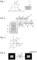
Fig. 1 is a block diagram illustrating a schematic configuration of a radiographic image capturing apparatus; -
Fig. 2 is a block diagram illustrating an example of a hardware configuration of an information processing apparatus; -
Fig. 3 is a diagram depicting structure information; -
Fig. 4 is a diagram depicting a trained model; -
Fig. 5 is a block diagram illustrating an example of a functional configuration of the information processing apparatus; -
Fig. 6 is a diagram depicting a process of deriving an irradiation direction; -
Fig. 7 is a diagram depicting a process of deriving a position of a discontinuity in the structure information; -
Fig. 8 is a diagram depicting a relationship between a depth of a discontinuity and a degree of blur of a region of the discontinuity in an inspection image; -
Fig. 9 is a diagram depicting a process of deriving a position of a discontinuity on the basis of a plurality of inspection images; -
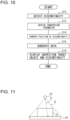
Fig. 10 is a flowchart illustrating an example of a discontinuity position conversion process; and -
Fig. 11 is a diagram illustrating an example of an irradiation direction according to a modification. - Hereinafter, exemplary embodiments for implementing the technology of the present disclosure will be described in detail with reference to the drawings.
- First, a configuration of a radiographic
image capturing apparatus 1 according to the present embodiment will be described with reference toFig. 1 . The radiographicimage capturing apparatus 1 is used for the non-destructive inspection of an inspection target object. As illustrated inFig. 1 , the radiographicimage capturing apparatus 1 includes aninformation processing apparatus 10, aradiation source 12, and aradiation detector 14. Theinformation processing apparatus 10, theradiation source 12, and theradiation detector 14 are communicably connected to each other. Theinformation processing apparatus 10 is, for example, a computer such as a personal computer or a server computer. - The
radiation source 12 irradiates an inspection target object O with radiation R such as X-rays. Theradiation source 12 according to the present embodiment emits the radiation R in a cone-beam shape. A direction from theradiation source 12 to one point on theradiation detector 14 at which the radiation R transmitted through the inspection target object O arrives is referred to as an "irradiation direction D". In the present embodiment, a case where a direction from theradiation source 12 to one point on theradiation detector 14 at which the radiation R transmitted through the center of the inspection target object O arrives is set as the irradiation direction D will be described as an example. - The
radiation detector 14 includes a scintillator as an example of a light emitting layer that emits light when irradiated with the radiation R, and a thin film transistor (TFT) substrate. The scintillator and the TFT substrate are laminated together. The TFT substrate includes a plurality of pixels arranged in a two-dimensional manner, and each pixel includes a field-effect thin film transistor and a sensor unit as an example of a conversion element in which generated charge increases as the amount of radiation to be emitted increases. The sensor unit absorbs light emitted by the scintillator to generate charge, and accumulates the generated charge. The field-effect thin film transistor converts the charge accumulated in the sensor unit into an electrical signal and outputs the electrical signal. With the above configuration, theradiation detector 14 generates a two-dimensional radiographic image corresponding to the radiation R emitted from theradiation source 12 to the inspection target object O, and outputs the generated radiographic image to theinformation processing apparatus 10. - In this manner, in the radiographic
image capturing apparatus 1, a radiographic image captured by irradiating the inspection target object O with the radiation R from theradiation source 12 along the irradiation direction D is stored in theinformation processing apparatus 10. A radiographic image captured by irradiating the inspection target object O with the radiation R along the irradiation direction D is hereinafter referred to as an "inspection image". - Next, a hardware configuration of the
information processing apparatus 10 according to the present embodiment will be described with reference toFig. 2 . As illustrated inFig. 2 , theinformation processing apparatus 10 includes a central processing unit (CPU) 20, amemory 21 serving as a temporary storage area, and anon-volatile storage unit 22. Theinformation processing apparatus 10 further includes adisplay 23 such as a liquid crystal display, aninput device 24 such as a keyboard and a mouse, and a network interface (I/F) 25 to be connected to a network. Theinformation processing apparatus 10 further includes an external I/F 26 to which theradiation source 12 and theradiation detector 14 are to be connected. TheCPU 20, thememory 21, thestorage unit 22, thedisplay 23, theinput device 24, the network I/F 25, and the external I/F 26 are connected to abus 27. TheCPU 20 is an example of a processor according to the technology disclosed herein. - The
storage unit 22 is implemented by a hard disk drive (HDD), a solid state drive (SSD), a flash memory, or the like. Thestorage unit 22 serving as a storage medium stores aninformation processing program 30. TheCPU 20 reads theinformation processing program 30 from thestorage unit 22, loads theinformation processing program 30 into thememory 21, and executes the loadedinformation processing program 30. - The
storage unit 22 further stores an inspection image,structure information 32, and a trainedmodel 34. Thestructure information 32 includes information representing a three-dimensional structure of the inspection target object O. As illustrated inFig. 3 , thestructure information 32 according to the present embodiment is information used when a virtual inspection target object O is displayed on thedisplay 23, and is information representing the three-dimensional structure of the inspection target object O by coordinates in an orthogonal coordinate system constituted by three axes, namely, an X axis, a Y axis, and a Z axis. Thestructure information 32 also includes materials of the parts of the inspection target object O. The material of each part specifies the transmittance of the radiation R through the part. Examples of thestructure information 32 include design information such as CAD data. - As illustrated in
Fig. 4 , the trainedmodel 34 is a trained model that receives an inspection image as an input and outputs information on a discontinuity of the inspection target object O in the inspection image as the input, and is a trained model trained by using a plurality of sets of inspection images and information on a discontinuity of the inspection target object O in the inspection images as learning data (also referred to as labeled training data). Examples of the information on the discontinuity include the position of the discontinuity in the inspection image, the size of the discontinuity, and the shape of the discontinuity. In the present embodiment, the position of the discontinuity in the inspection image is represented by coordinates in an orthogonal coordinate system in which a specific point (e.g., a point at the upper left corner) of the two-dimensional inspection image is taken as the origin and that is constituted by two axes, namely, an X axis and a Y axis. In this specification, the "discontinuity" is defined as a term of non-destructive inspection and means a discontinuity such as a bubble, a foreign substance, or a crack. - Next, a functional configuration of the
information processing apparatus 10 according to the present embodiment will be described with reference toFig. 5 . As illustrated inFig. 5 , theinformation processing apparatus 10 includes adetection unit 40, afirst derivation unit 42, asecond derivation unit 44, ageneration unit 46, and adisplay control unit 48. TheCPU 20 executes theinformation processing program 30 to function as thedetection unit 40, thefirst derivation unit 42, thesecond derivation unit 44, thegeneration unit 46, and thedisplay control unit 48. - The
detection unit 40 detects, based on the inspection image and the trainedmodel 34 stored in thestorage unit 22, a discontinuity of the inspection target object O in the inspection image. Specifically, thedetection unit 40 inputs the inspection image to the trainedmodel 34. The trainedmodel 34 outputs information on the discontinuity of the inspection target object O corresponding to the input inspection image. Accordingly, thedetection unit 40 detects the discontinuity of the inspection target object O in the inspection image. - The
detection unit 40 may detect the discontinuity of the inspection target object O in the inspection image by a known detection algorithm. The discontinuity of the inspection target object O in the inspection image may be designated by the user via theinput device 24. In this case, thedetection unit 40 detects the discontinuity designated by the user. - The
first derivation unit 42 derives a conversion parameter that is for converting a position in the two-dimensional inspection image into a position in the three-dimensional structure information 32 and that includes the irradiation direction D in thestructure information 32. A specific example of a process of deriving the irradiation direction D in thestructure information 32 by thefirst derivation unit 42 will be described with reference toFig. 6 . - As illustrated on the right side of
Fig. 6 , the two-dimensional inspection image is obtained by being captured by irradiating the inspection target object O with the radiation R along the irradiation direction D from theradiation source 12. As illustrated on the left side ofFig. 6 , thefirst derivation unit 42 generates a two-dimensional simulation image by projecting the inspection target object O along a viewpoint direction for a virtual inspection target object O displayed on thedisplay 23 on the basis of thestructure information 32. The viewpoint direction is a direction in which when the virtual inspection target object O is viewed, the surface of the inspection target object O appears as the front surface of the display screen. The example on the left side ofFig. 6 presents an example in which a simulation image when the virtual inspection target object O based on thestructure information 32 is viewed from the right side ofFig. 6 , that is, in the direction of an arrow A, is generated. For example, the viewpoint direction is represented by coordinates of one point, and a direction passing through the origin from the coordinates is the viewpoint direction. - The
first derivation unit 42 generates respective simulation images for a plurality of different viewpoint directions. Further, thefirst derivation unit 42 derives a level of similarity between each of the generated simulation images and the inspection image. Specifically, for example, thefirst derivation unit 42 derives a level of similarity between the silhouette of the inspection target object O in the simulation image and the silhouette of the inspection target object O in the inspection image. Thefirst derivation unit 42 may extract a contour line of the inspection target object O in the simulation image and a contour line of the inspection target object O in the inspection image and derive a level of similarity between outer shapes of the inspection target object O configured by the extracted contour lines. - Then, the
first derivation unit 42 sets the viewpoint direction for the simulation image having the highest level of similarity to the inspection image as the irradiation direction D in thestructure information 32. - The
second derivation unit 44 derives the three-dimensional coordinates of the discontinuity in thestructure information 32 by converting the position of the discontinuity of the inspection target object O in the inspection image detected by thedetection unit 40 into the position of the discontinuity in thestructure information 32 by using the irradiation direction D derived by thefirst derivation unit 42. Thesecond derivation unit 44 may acquire the irradiation direction D derived by an external device, instead of thefirst derivation unit 42, via the network I/F 25. - Specifically, first, the
second derivation unit 44 converts the position of the discontinuity of the inspection target object O in the inspection image into the position in thestructure information 32 in a plane for which the irradiation direction D is set as the viewpoint direction. For example, thesecond derivation unit 44 can perform the conversion described above by a process of matching the scale of the outer shape of the inspection target object O in the inspection image with the scale of the outer shape of the virtual inspection target object O viewed from the irradiation direction D in thestructure information 32. - In this way, the position of the discontinuity of the inspection target object O in a plane in a case where the virtual inspection target object O is viewed from the irradiation direction D in the
structure information 32 can be determined. Accordingly, as illustrated inFig. 7 , if a depth L of the discontinuity along the irradiation direction D can be determined, the three-dimensional coordinates of the discontinuity in thestructure information 32 can be determined. - The
second derivation unit 44 according to the present embodiment derives the depth of the discontinuity along the irradiation direction D on the basis of one inspection image. As illustrated inFig. 8 , as the depth of the discontinuity along the irradiation direction D decreases, that is, as the distance of the discontinuity from theradiation detector 14 increases, the degree of blur of the region of the discontinuity in the inspection image increases. This is because the farther the discontinuity is from theradiation detector 14, the more likely it is that the discontinuity is affected by scattered radiation or the like. Accordingly, thesecond derivation unit 44 derives the depth of the discontinuity along the irradiation direction D on the basis of the degree of blur of the region of the discontinuity in the inspection image. Specifically, thesecond derivation unit 44 derives the depth of the discontinuity along the irradiation direction D as a larger value for a larger degree of blur of the region of the discontinuity in the inspection image. Then, thesecond derivation unit 44 derives a position separated from the position corresponding to the surface of the inspection target object O in thestructure information 32 by the derived depth along the irradiation direction D as the position of the discontinuity in the structure information. - The above processing allows the
second derivation unit 44 to convert the position of the discontinuity of the inspection target object O in the two-dimensional inspection image into the three-dimensional coordinates in thestructure information 32. - The
second derivation unit 44 may convert the position of the discontinuity of the inspection target object O in the inspection image into the position of the discontinuity in thestructure information 32 on the basis of a plurality of inspection images captured from a plurality of different irradiation directions D. In this case, thesecond derivation unit 44 converts the position of the discontinuity in each of the plurality of inspection images into a position in thestructure information 32 in a plane for which each of the irradiation directions D is set as the viewpoint direction, by using the irradiation directions D derived by thefirst derivation unit 42. Then, as illustrated inFig. 9 , thesecond derivation unit 44 derives, as the position of the discontinuity in thestructure information 32, an intersection point P of a plurality of straight lines each extending along one of the irradiation directions D and each passing through the position of the discontinuity after the conversion for one of the plurality of inspection images.Fig. 9 illustrates an example for two inspection images. - The
generation unit 46 generates data in which thestructure information 32 and the position of the discontinuity in thestructure information 32 derived by thesecond derivation unit 44 are integrated. For example, thegeneration unit 46 generates data in which the position of the discontinuity in thestructure information 32 derived by thesecond derivation unit 44 is included in the property of a data file representing thestructure information 32. - The
display control unit 48 performs control to display the virtual inspection target object O and an object representing the discontinuity on thedisplay 23 on the basis of the data generated by thegeneration unit 46. The object representing the discontinuity may be, for example, a mark such as a circle or an image of the region of the discontinuity in the inspection image. - Next, the operation of the
information processing apparatus 10 according to the present embodiment will be described with reference toFig. 10 . When theCPU 20 executes theinformation processing program 30, a discontinuity position conversion process illustrated inFig. 10 is executed. The discontinuity position conversion process illustrated inFig. 10 is executed when, for example, the user inputs an instruction to start execution of the discontinuity position conversion process. - In step S10 of
Fig. 10 , as described above, thedetection unit 40 detects, based on the inspection image and the trainedmodel 34 stored in thestorage unit 22, a discontinuity of the inspection target object O in the inspection image. In step S12, as described above, thefirst derivation unit 42 derives a conversion parameter that is for converting a position in the two-dimensional inspection image into a position in the three-dimensional structure information 32 and that includes the irradiation direction D in thestructure information 32. - In step S14, as described above, the
second derivation unit 44 converts the position of the discontinuity of the inspection target object O in the inspection image detected in step S10 into the position of the discontinuity in thestructure information 32 by using the irradiation direction D derived in step S12. - In step S16, the
generation unit 46 generates data in which thestructure information 32 and the position of the discontinuity in thestructure information 32 derived in step S14 are integrated. In step S18, thedisplay control unit 48 performs control to display the virtual inspection target object O and an object representing the discontinuity on thedisplay 23 on the basis of the data generated in step S16. When the processing of step S18 is finished, the discontinuity position conversion process ends. - As described above, according to the present embodiment, the position of the discontinuity of the inspection target object O can be determined as a three-dimensional position on the basis of not a tomographic image such as a CT image but a simple X-ray image. This allows the user to grasp the position of the discontinuity of the inspection target object O as a three-dimensional position. According to the present embodiment, therefore, the inspection efficiency of non-destructive inspection can be improved.
- In the embodiment described above, as illustrated in
Fig. 11 , when thesecond derivation unit 44 derives the three-dimensional coordinates of the discontinuity, the irradiation direction D may be set to a direction inclined with respect to the direction from theradiation source 12 to the center of the inspection target object O. - In the embodiment described above, furthermore, the conversion parameter may include correction data for correcting a distortion of the inspection image, in addition to the irradiation direction D.
- In the embodiment described above, furthermore, the hardware structures of processing units that execute various processes, such as the functional units of the
information processing apparatus 10, may be implemented using various processors described below. As described above, the various processors described above include a CPU that is a general-purpose processor configured to execute software (program) to function as various processing units, and further include a programmable logic device (PLD) that is a processor whose circuit configuration can be changed after manufacturing, such as a field programmable gate array (FPGA), a dedicated electric circuit that is a processor having a circuit configuration designed exclusively for executing specific processing, such as an application specific integrated circuit (ASIC), and so on. - One processing unit may be constituted by one of these various processors, or may be constituted by a combination of two or more processors of the same type or different types (e.g., a combination of a plurality of FPGAs or a combination of a CPU and an FPGA). Alternatively, a plurality of processing units may be configured by one processor.
- Examples of configuring a plurality of processing units by one processor include, first, a form in which, as typified by a computer such as a client and a server, one processor is configured by a combination of one or more CPUs and software and the processor functions as a plurality of processing units. The examples include, second, a form in which, as typified by a system on chip (SoC) or the like, a processor is used that implements the functions of the entire system including a plurality of processing units by one integrated circuit (IC) chip. As described above, the various processing units are configured by using one or more of the various processors described above as a hardware structure.
- More specifically, the hardware structure of these various processors may be an electric circuit (circuitry) in which circuit elements such as semiconductor elements are combined.
- The embodiment described above has described an embodiment in which the
information processing program 30 is stored (installed) in thestorage unit 22 in advance, but is not limited to this embodiment. Theinformation processing program 30 may be provided in a form recorded in recording media such as a compact disc read only memory (CD-ROM), a digital versatile disc read only memory (DVD-ROM), and a universal serial bus (USB) memory. Alternatively, in an embodiment, theinformation processing program 30 may be downloaded from an external device via a network. - The disclosure of
JP2022-099870 filed on June 21, 2022
Claims (7)
- An information processing apparatus comprising:at least one processor,wherein the processor is configured to:acquire a conversion parameter for converting a position in an inspection image captured by irradiating an inspection target object with radiation along an irradiation direction into a position in structure information representing a three-dimensional structure of the inspection target object, the conversion parameter including the irradiation direction in the structure information; andconvert a position of a discontinuity of the inspection target object in the inspection image into a position in the structure information by using the conversion parameter.
- The information processing apparatus according to claim 1, wherein:
the processor is configured to:derive a depth of the discontinuity along the irradiation direction, based on the inspection image; andderive, as a position of the discontinuity in the structure information, a position separated from a position corresponding to a surface of the inspection target object in the structure information by the derived depth along the irradiation direction. - The information processing apparatus according to claim 2, wherein:the processor is configured toderive the depth of the discontinuity, based on a degree of blur of a region of the discontinuity in the inspection image.
- The information processing apparatus according to claim 1, wherein:a plurality of the inspection images are captured from a plurality of different irradiation directions, andthe processor is configured to:convert a position of the discontinuity in each of the plurality of the inspection images into a position in the structure information in a plane for which each of the irradiation directions is set as a viewpoint direction, by using the conversion parameter; andderive, as a position of the discontinuity in the structure information, an intersection point of a plurality of straight lines each extending along one of the irradiation directions and each passing through the position of the discontinuity after conversion for one of the plurality of the inspection images.
- The information processing apparatus according to any one of claims 1 to 4, wherein:the processor is configured tointegrate the structure information and a position of the discontinuity in the structure information into data.
- An information processing method in which a processor included in an information processing apparatus executes processing comprising:acquiring a conversion parameter for converting a position in an inspection image captured by irradiating an inspection target object with radiation along an irradiation direction into a position in structure information representing a three-dimensional structure of the inspection target object, the conversion parameter including the irradiation direction in the structure information; andconverting a position of a discontinuity of the inspection target object in the inspection image into a position in the structure information by using the conversion parameter.
- An information processing program for causing a processor included in an information processing apparatus to execute processing comprising:acquiring a conversion parameter for converting a position in an inspection image captured by irradiating an inspection target object with radiation along an irradiation direction into a position in structure information representing a three-dimensional structure of the inspection target object, the conversion parameter including the irradiation direction in the structure information; andconverting a position of a discontinuity of the inspection target object in the inspection image into a position in the structure information by using the conversion parameter.
Applications Claiming Priority (2)
| Application Number | Priority Date | Filing Date | Title |
|---|---|---|---|
| JP2022099870 | 2022-06-21 | ||
| PCT/JP2023/014617 WO2023248583A1 (en) | 2022-06-21 | 2023-04-10 | Information processing device, information processing method, and information processing program |
Publications (2)
| Publication Number | Publication Date |
|---|---|
| EP4545952A1 true EP4545952A1 (en) | 2025-04-30 |
| EP4545952A4 EP4545952A4 (en) | 2025-10-22 |
Family
ID=89379525
Family Applications (1)
| Application Number | Title | Priority Date | Filing Date |
|---|---|---|---|
| EP23826772.8A Pending EP4545952A4 (en) | 2022-06-21 | 2023-04-10 | INFORMATION PROCESSING DEVICE, INFORMATION PROCESSING METHOD AND INFORMATION PROCESSING PROGRAM |
Country Status (5)
| Country | Link |
|---|---|
| US (1) | US20250095139A1 (en) |
| EP (1) | EP4545952A4 (en) |
| JP (1) | JPWO2023248583A1 (en) |
| CN (1) | CN119325561A (en) |
| WO (1) | WO2023248583A1 (en) |
Family Cites Families (11)
| Publication number | Priority date | Publication date | Assignee | Title |
|---|---|---|---|---|
| US5550376A (en) * | 1995-05-22 | 1996-08-27 | General Electric Company | Method of calibration of imaging devices |
| US7602963B2 (en) | 2006-01-10 | 2009-10-13 | General Electric Company | Method and apparatus for finding anomalies in finished parts and/or assemblies |
| JP5365010B2 (en) * | 2008-01-24 | 2013-12-11 | 株式会社島津製作所 | X-ray fluoroscopic three-dimensional observation method and X-ray fluoroscopic apparatus |
| JP2009276142A (en) * | 2008-05-13 | 2009-11-26 | Hitachi Ltd | Radiographic inspection system and imaging method of radiographic inspection |
| JP2015052472A (en) * | 2013-09-05 | 2015-03-19 | アイシン精機株式会社 | Defect inspection apparatus and defect inspection method |
| JP6763301B2 (en) * | 2014-09-02 | 2020-09-30 | 株式会社ニコン | Inspection equipment, inspection methods, inspection processing programs and structure manufacturing methods |
| EP3673809B1 (en) * | 2014-09-16 | 2024-07-17 | Sirona Dental, Inc. | Method and computer program for processing tomographic images |
| WO2018034056A1 (en) * | 2016-08-18 | 2018-02-22 | 富士フイルム株式会社 | Defect inspection device, defect inspection method, and program |
| US10919285B2 (en) * | 2016-11-07 | 2021-02-16 | General Electric Company | Method and system for x-ray backscatter inspection of additive manufactured parts |
| US11688067B2 (en) * | 2019-07-12 | 2023-06-27 | Bruker Nano, Inc. | Methods and systems for detecting defects in devices using X-rays |
| JP2022099870A (en) | 2020-12-23 | 2022-07-05 | 三星電子株式会社 | Refrigerant distributor and heat exchanger having refrigerant distributor |
-
2023
- 2023-04-10 JP JP2024528326A patent/JPWO2023248583A1/ja active Pending
- 2023-04-10 EP EP23826772.8A patent/EP4545952A4/en active Pending
- 2023-04-10 WO PCT/JP2023/014617 patent/WO2023248583A1/en not_active Ceased
- 2023-04-10 CN CN202380045638.4A patent/CN119325561A/en active Pending
-
2024
- 2024-11-28 US US18/963,487 patent/US20250095139A1/en active Pending
Also Published As
| Publication number | Publication date |
|---|---|
| US20250095139A1 (en) | 2025-03-20 |
| CN119325561A (en) | 2025-01-17 |
| EP4545952A4 (en) | 2025-10-22 |
| WO2023248583A1 (en) | 2023-12-28 |
| JPWO2023248583A1 (en) | 2023-12-28 |
Similar Documents
| Publication | Publication Date | Title |
|---|---|---|
| CN110859638B (en) | Image processing device, image processing method and storage medium | |
| JP7084291B2 (en) | Tomosynthesis photography support equipment, methods and programs | |
| Li et al. | Interactive tooth separation from dental model using segmentation field | |
| CN107525815B (en) | System and Method for Detecting Baggage in Imaging System | |
| US7564998B2 (en) | Image processing apparatus and method, and program | |
| CN110634554A (en) | Spine image registration method | |
| US12086923B2 (en) | Surface determination using three-dimensional voxel data | |
| US9763636B2 (en) | Method and system for spine position detection | |
| JP6185262B2 (en) | Nuclear medicine bone image analysis technology | |
| JP7212000B2 (en) | Information processing device, information processing method, and information processing program | |
| EP4545952A1 (en) | Information processing device, information processing method, and information processing program | |
| CN102711611B (en) | Radiograph processing device and radiograph processing program | |
| US20210393226A1 (en) | Image processing apparatus, image processing method, and image processing program | |
| Hussien et al. | Stereo photogrammetry vs computed tomography for 3D medical measurements | |
| EP4553491A1 (en) | Information processing device, information processing method, and information processing program | |
| US11963810B2 (en) | Estimation device, estimation method, and estimation program | |
| JP6827786B2 (en) | Contour extractor, contour extraction method and program | |
| JP2024028042A (en) | Information processing device, information processing method, and program | |
| JP6696237B2 (en) | Similar image search program, similar image search method, and similar image search device | |
| EP4675263A1 (en) | Display control device, display control method, and display control program | |
| EP4545951A1 (en) | Display control device, display control method, and display control program | |
| Babaee et al. | Synthetic data generation for X-ray imaging | |
| JP6386629B2 (en) | Nuclear medicine bone image analysis technology | |
| JP2020178894A (en) | Image processing apparatus, method and program | |
| US20250102450A1 (en) | Imaging jig and information processing apparatus |
Legal Events
| Date | Code | Title | Description |
|---|---|---|---|
| STAA | Information on the status of an ep patent application or granted ep patent |
Free format text: STATUS: THE INTERNATIONAL PUBLICATION HAS BEEN MADE |
|
| PUAI | Public reference made under article 153(3) epc to a published international application that has entered the european phase |
Free format text: ORIGINAL CODE: 0009012 |
|
| STAA | Information on the status of an ep patent application or granted ep patent |
Free format text: STATUS: REQUEST FOR EXAMINATION WAS MADE |
|
| 17P | Request for examination filed |
Effective date: 20241218 |
|
| AK | Designated contracting states |
Kind code of ref document: A1 Designated state(s): AL AT BE BG CH CY CZ DE DK EE ES FI FR GB GR HR HU IE IS IT LI LT LU LV MC ME MK MT NL NO PL PT RO RS SE SI SK SM TR |
|
| DAV | Request for validation of the european patent (deleted) | ||
| DAX | Request for extension of the european patent (deleted) | ||
| A4 | Supplementary search report drawn up and despatched |
Effective date: 20250918 |
|
| RIC1 | Information provided on ipc code assigned before grant |
Ipc: G01N 23/18 20180101AFI20250912BHEP Ipc: G01N 23/04 20180101ALI20250912BHEP Ipc: G01N 23/083 20180101ALI20250912BHEP Ipc: G06T 5/00 20240101ALI20250912BHEP |