EP4545914A1 - ELECTROMAGNETIC FLOW METER - Google Patents
ELECTROMAGNETIC FLOW METER Download PDFInfo
- Publication number
- EP4545914A1 EP4545914A1 EP24208008.3A EP24208008A EP4545914A1 EP 4545914 A1 EP4545914 A1 EP 4545914A1 EP 24208008 A EP24208008 A EP 24208008A EP 4545914 A1 EP4545914 A1 EP 4545914A1
- Authority
- EP
- European Patent Office
- Prior art keywords
- excitation coil
- magnetic
- path
- flow meter
- electromagnetic flow
- Prior art date
- Legal status (The legal status is an assumption and is not a legal conclusion. Google has not performed a legal analysis and makes no representation as to the accuracy of the status listed.)
- Pending
Links
Images




Classifications
-
- G—PHYSICS
- G01—MEASURING; TESTING
- G01F—MEASURING VOLUME, VOLUME FLOW, MASS FLOW OR LIQUID LEVEL; METERING BY VOLUME
- G01F1/00—Measuring the volume flow or mass flow of fluid or fluent solid material wherein the fluid passes through a meter in a continuous flow
- G01F1/56—Measuring the volume flow or mass flow of fluid or fluent solid material wherein the fluid passes through a meter in a continuous flow by using electric or magnetic effects
- G01F1/58—Measuring the volume flow or mass flow of fluid or fluent solid material wherein the fluid passes through a meter in a continuous flow by using electric or magnetic effects by electromagnetic flowmeters
- G01F1/588—Measuring the volume flow or mass flow of fluid or fluent solid material wherein the fluid passes through a meter in a continuous flow by using electric or magnetic effects by electromagnetic flowmeters combined constructions of electrodes, coils or magnetic circuits, accessories therefor
-
- G—PHYSICS
- G01—MEASURING; TESTING
- G01F—MEASURING VOLUME, VOLUME FLOW, MASS FLOW OR LIQUID LEVEL; METERING BY VOLUME
- G01F1/00—Measuring the volume flow or mass flow of fluid or fluent solid material wherein the fluid passes through a meter in a continuous flow
- G01F1/56—Measuring the volume flow or mass flow of fluid or fluent solid material wherein the fluid passes through a meter in a continuous flow by using electric or magnetic effects
- G01F1/58—Measuring the volume flow or mass flow of fluid or fluent solid material wherein the fluid passes through a meter in a continuous flow by using electric or magnetic effects by electromagnetic flowmeters
- G01F1/586—Measuring the volume flow or mass flow of fluid or fluent solid material wherein the fluid passes through a meter in a continuous flow by using electric or magnetic effects by electromagnetic flowmeters constructions of coils, magnetic circuits, accessories therefor
-
- G—PHYSICS
- G01—MEASURING; TESTING
- G01F—MEASURING VOLUME, VOLUME FLOW, MASS FLOW OR LIQUID LEVEL; METERING BY VOLUME
- G01F1/00—Measuring the volume flow or mass flow of fluid or fluent solid material wherein the fluid passes through a meter in a continuous flow
- G01F1/56—Measuring the volume flow or mass flow of fluid or fluent solid material wherein the fluid passes through a meter in a continuous flow by using electric or magnetic effects
- G01F1/58—Measuring the volume flow or mass flow of fluid or fluent solid material wherein the fluid passes through a meter in a continuous flow by using electric or magnetic effects by electromagnetic flowmeters
- G01F1/584—Measuring the volume flow or mass flow of fluid or fluent solid material wherein the fluid passes through a meter in a continuous flow by using electric or magnetic effects by electromagnetic flowmeters constructions of electrodes, accessories therefor
Definitions
- the present invention relates to an electromagnetic flow meter.
- An electromagnetic flow meter has been used as a measurement device used to measure a flow rate of a conductive fluid, such as tap water, flowing through a measurement tube (for example, JP-A-2005-172645 , JP-A-9-145435 , and JP-A-5-256674 ).
- the present invention has been achieved in view of the above problem, and aims to improve the measurement accuracy of the electromagnetic flow meter.
- an electromagnetic flow meter that measures a flow rate of a conductive fluid flowing through a measuring tube, includes an excitation coil that is arranged in the measuring tube, and that generates a magnetic field in a direction perpendicular to a tube axis of the measuring tube, a return magnetic path that is arranged on a side surface in a circumferential direction of a tube axis including the excitation coil in the measuring tube, and that concentrates the magnetic field generated by the excitation coil to an inside of the measuring tube, and a return magnetic-path auxiliary member that is arranged on at least one of an outer diameter side and an inner diameter side in the direction perpendicular to the tube axis of the excitation coil, and that complements a function of the return magnetic path.
- FIG. 1 is a diagram illustrating an example of a cross-section in a direction perpendicular to a tube axis of the electromagnetic flow meter 10 according to the embodiment.
- FIG. 2 is a diagram illustrating an example of a cross-section in a direction parallel to the tube axis of the electromagnetic flow meter 10 according to the embodiment.
- the electromagnetic flow meter 10 includes a measuring tube 1, a lining material 2, an excitation coil 3, an electrode 5, a return magnetic path 6, a return magnetic-path cover 7, a return magnetic-path sheet 8, and a fixing member 9. Moreover, the electromagnetic flow meter 10 measures the flow rate of a conductive fluid 4 flowing inside the measuring tube 1.
- the electromagnetic flow meter 10 is a measuring device used to measure a flow rate of a conductive fluid 4 such as tap water.
- the measuring tube 1 is made of a non-magnetic metal with corrosion resistance, such as austenitic stainless steel.
- the lining material 2 is an insulator that covers an inner tube surface of the measuring tube 1.
- a pair of the excitation coils 3 (3a, 3b) are arranged at a position perpendicular to a tube axis, which corresponds to an upper portion and a bottom portion of the measuring tube 1, and generate a magnetic field inside the measuring tube 1.
- a pair of the electrodes 5 are arranged at a position in a direction perpendicular to the tube axis of the measuring tube 1 and perpendicular to the arrangement position of the excitation coils 3.
- an electromotive force is generated in the direction perpendicular to the magnetic field generated by the excitation coil 3 and in the direction perpendicular to the tube axis.
- the electromagnetic flow meter 10 detects the generated electromotive force with the electrodes 5 (5a, 5b), and converts it to a flow rate of the conductive fluid 4.
- the return magnetic path 6 has a function of concentrating the magnetic field generated by the excitation coil 3 to the inside of the measuring tube 1 including the electrodes 5, and is constituted of a ferromagnetic material such as silicon steel plate.
- the electromagnetic flow meter 10 includes at least one of the return magnetic-path cover 7 and the return magnetic-path sheet 8 as a return magnetic-path auxiliary member that complements the properties of the return magnetic path 6.
- the return magnetic-path cover 7 has a first function as a magnetic shield that confines the magnetic field generated by the excitation coil, and a second function of reinforcing the magnetic field in a central portion of the excitation coil 3 as an electromagnet.
- the return magnetic-path cover 7 is arranged to cover the excitation coils 3 and a side surface in a circumferential direction of the tube axis of the return magnetic path 6. Moreover, particularly as illustrated in FIG. 2 , it has a shape entering inside (inwardly extending into) a gap of the excitation coil 3.
- the return magnetic-path cover 7 has a first function of shielding such that the magnetic field generated by the excitation coil 3 is not to leak outside, arranged on a side surface in a circumferential direction of a tube axis. Moreover, the return magnetic-path cover 7 has a second function of reinforcing the magnetic field generated by the excitation coil 3 as an electromagnet with its shape extending inwardly to the inside of the gap of the excitation coil 3. In this case, the return magnetic-path cover 7 is fixed to overlap with the return magnetic path 6 in the direction perpendicular to the tube axis inside the gap of the excitation coil 3 by a fixing member 9, and the magnetic field is further reinforced as an electromagnet by increasing the volume of the ferromagnetic material inside the gap of the excitation coil 3.
- the return magnetic-path sheet 8 has a first function of absorbing the magnetic field generated by the excitation coil, and a second function of reinforcing the magnetic field of a central portion of the excitation coil 3 as an electromagnet.
- the return magnetic-path sheet 8 has a slit that is cut avoiding portions directly beneath the excitation coil 3, and has a shape to cover the inner portion of the gap on a bottom surface (grounding surface) of the excitation coil 3 and peripheral portions on the bottom surface of the excitation coil 3.
- the return magnetic-path sheet 8 prevents the magnetic field generated by the excitation coil 3 from being drawn toward the counterpart piping by being arranged at the peripheral portions on the bottom surface of the excitation coil 3. In this case, the return magnetic-path sheet 8 exerts the first function of absorbing the magnetic flux of the magnetic field generated by the excitation coil 3. Moreover, the return magnetic-path sheet 8 exerts the second function of reinforcing the magnetic field generated by the excitation coil 3 as an electromagnet by being arranged inside the gap on the bottom surface of the excitation coil 3.
- the return magnetic-path sheet 8 has the slit so as to avoid the portion directly beneath the excitation coil 3, it does not interfere a flow of the magnetic field generated by the excitation coil 3 to a flow path of the measuring tube 1.
- the return magnetic-path sheet 8 is only required to have a hollow directly beneath the bottom surface of the excitation coil 3, and to fill other portions, which are the inside of the gap on the bottom surface of the excitation coil 3 and the peripheral portion on the bottom surface of the excitation coil 3, with ferromagnetic material.
- Reference Technique 1 is a wafer-type electromagnetic flow meter equipped with a mini flange, and is an electromagnetic flow meter including a shielding plate made of magnetic material that is arranged on a flange portion parallel to a plane of the mini flange, and that shields leakage of magnetic flux in a direction of a flow of a measurement fluid from an excitation coil.
- Reference Technique 2 is an electromagnetic flow meter that includes a coil serving as a magnetic field generating means generating a magnetic field orthogonal to a flow of a measurement fluid in a measuring tube, at least a pair of electrodes arranged to face each other on a diameter of the measuring tube to measure an electromotive force generated by an action of the magnetic field, and magnetic shielding plates that are arranged to be flanges at both ends of the measuring tube having a small influence to the magnetic field.
- Reference Technique 3 is an electromagnetic flow-rate detector in which a high-permeability magnetic metal ring positioned at an outer end of a measuring tube and a concentric high-permeability side magnetic path are integrated into a single cast structure.
- Related technique 1 and Related technique 2 are techniques in which a portion at a position distant from the excitation coil is shielded.
- a gap between a return magnetic path and a magnetic shield is large, and it is difficult to efficiently suppress leakage of magnetic flux from the excitation coil to a counterpart piping.
- Reference Technique 3 when an iron-based ferromagnetic material is used as a material for the magnetic shield of the electromagnetic flow meter considering cost and the like, the ion-based material cannot be directly exposed to fluids or external environments because it is significantly inferior in corrosion resistance, and strong rust can form as a result of reacting with a lining material, such as Perfluoroalkoxy alkane (PFA), that is injection-molded onto an inner wall of a pipe in the electromagnetic flow meter.
- PFA Perfluoroalkoxy alkane
- Reference Technique 3 when austenitic stainless steel, which has high corrosion resistance, is used for the detector, and an iron-based material is used as the magnetic shield at a part of the interior of the detector, the same problem as those in Reference Technique 1 and Reference Technique 2 described above arises.
- the electromagnetic flow meter 10 optimizes the structure and the shape of the return magnetic path 6, and at least one of the return magnetic-path cover 7 and the return magnetic-path sheet 8 is equipped as a return magnetic-path auxiliary member that complements the properties of the return magnetic path 6, thereby improving the magnetic shield properties without significant cost increase, and improving the return efficiency of the magnetic flux in a flow path portion. That is, the electromagnetic flow meter 10 can improve the measuring accuracy.
- the configuration example and the function example of the electromagnetic flow meter 10 will be explained in detail in order of the measuring tube 1, the lining material 2, the excitation coil 3, the electrode 5, the return magnetic path 6, the return magnetic-path cover 7, the return magnetic-path sheet 8, and the fixing member 9.
- the measuring tube 1 is arranged in a counterpart pipe in which the conductive fluid 4 to be measured flows, and is a tube in a cylindrical shape forming a flow path of the conductive fluid 4. Moreover, the measuring tube 1 is constituted of a non-magnetic metal having corrosion resistance, such as austenitic stainless steel.
- the lining material 2 is an insulating material that covers an inner portion in a tube of the measuring tube 1.
- the lining material 2 is constituted of an insulating material, such as PFA, that is injection molded onto an inner wall inside the tubular path of the measuring tube 1.
- the excitation coil 3 is arranged in the measuring tube 1, and generates a magnetic field in a direction perpendicular to the tube axis of the measuring tube 1.
- the excitation coil 3 is arranged on an outer diameter side in the direction perpendicular to the tube axis of the measuring tube 1 as a pair of the excitation coil 3a and the excitation coil 3b facing each other, and generates a magnetic field in the measuring tube 1 between the pair of the excitation coil 3a and the excitation coil 3b.
- the electrode 5 is arranged in the measuring tube 1. It is arranged in the perpendicular position to the tube axis of the measuring tube 1 at a position perpendicular to an installation position of the excitation coil 3, and detects an electromotive force generated as the conductive fluid 4 flows inside the measuring tube 1.
- the electrode 5 is arranged as a pair of the electrode 5a and the electrode 5b facing each other on the outer diameter side in the direction perpendicular to the tube axis of the measuring tube 1, and detects a signal of an electromotive force that is generated in a direction perpendicular to the tube axis, and that is proportional to a flow rate of the conductive fluid 4 flowing inside the measuring tube 1.
- the return magnetic path 6 is a circuit that applies a magnetic field in a direction perpendicular to the flow path of the conductive fluid 4, and is arranged on a side surface in the circumferential direction of the tube axis including the excitation coil 3 in the measuring tube 1, and concentrates the magnetic field generated by the excitation coil 3 to the inside of the measuring tube 1.
- the return magnetic path 6 may be arranged on a side surface in the circumferential direction of a tube axis including all of a pair of the excitation coils 3 (3a, 3b) and a pair of the electrodes 5 (5a, 5b) in the measuring tube 1.
- the return magnetic path 6 is a ferromagnetic plate.
- the return magnetic path 6 is constituted of a silicon steel plate.
- the return magnetic-path cover 7 is arranged on at least one of an outer diameter side and an inner diameter side in the direction perpendicular to the tube axis of the excitation coil 3, and is one of the return magnetic-path auxiliary members that complements the function of the return magnetic path 6.
- the return magnetic-path cover 7 is arranged on the outer diameter side in the direction perpendicular to the tube axis of the excitation coil 3, and blocks movement of a magnetic flux toward the outer diameter side.
- the return magnetic-path cover 7 is arranged to extend inwardly to the gap of the excitation coil 3 on the outer diameter side in the direction perpendicular to the tube axis of the excitation coil 3, to reinforce the magnetic field generated by the excitation coil 3. Moreover, the return magnetic-path cover 7 is a plate of a ferromagnetic material.
- the return magnetic-path cover 7 has a structure extending inwardly to the gap of the excitation coil 3 on the outer diameter side in the direction perpendicular to the tube axis of the excitation coil 3.
- the return magnetic-path cover 7 has a separable structure so as to be arranged to cover either one out of a pair of the excitation coil 3a and the excitation coil 3b. That is, the return magnetic-path cover 7 illustrated in the example in FIG. 5 is arranged to cover both of a pair of the excitation coil 3a and the excitation coil 3b using two sets.
- the return magnetic-path cover 7 may have a structure to be arranged to cover all of a pair of the excitation coil 3a and the excitation coil 3b with a single part.
- the return magnetic-path cover 7 exerts the first function of blocking the magnetic field generated by the excitation coil 3 to prevent external leakage by being arranged on the side surface in the circumferential direction of a tube axis. Moreover, the return magnetic-path cover 7 exerts the second function of reinforcing the magnetic field generated by the excitation coil 3 as an electromagnet with the shape extending inwardly to the inside of the gap of the excitation coil 3.
- the return magnetic-path sheet 8 is arranged on at least one of the outer diameter side and the inner diameter side in the direction perpendicular to the tube axis of the excitation coil 3, and is one of the return magnetic-path auxiliary member that complements the function of the return magnetic path 6.
- the return magnetic-path sheet 8 is arranged on the inner diameter side in the direction perpendicular to the tube axis of the excitation coil 3, and absorbs the magnetic flux of the magnetic field toward the outer diameter side in the direction perpendicular to the tube axis of the excitation coil 3.
- the return magnetic-path sheet 8 is arranged on the inner diameter side in the direction perpendicular to the tube axis of the excitation coil 3 except a position at which the measuring tube 1 is arranged, and passes the magnetic flux of the magnetic field toward the inner diameter side, and reinforces the magnetic field generated by the excitation coil 3. Furthermore, the return magnetic-path sheet 8 is a plate of a ferromagnetic material.
- the return magnetic-path sheet 8 has a structure that is arranged on the inner diameter side in the direction perpendicular to the tube axis of the excitation coil 3.
- the return magnetic-path sheet 8 is only required to have a structure not obstructing the flow of the magnetic field into the flow path of the measuring tube 1, and to fill other portions, which is the inside of the gap on the bottom surface of the excitation coil 3 and the peripheral portion on the bottom surface of the excitation coil 3, with a ferromagnetic material.
- the return magnetic-path sheet 8-1 has a structure separated into three parts, to avoid being located directly beneath the excitation coil 3, and to cover the inside of the gap and the peripheral portions on the bottom surface of the excitation coil 3.
- the return magnetic-path sheet 8-2 has a structure in which four slits are formed, to avoid being located directly beneath the excitation coil 3, and to cover the inside of the gap and the peripheral portions on the bottom surface of the excitation coil 3.
- the return magnetic-path sheet 8-3 has a structure in which two hollows are formed, to avoid being located directly beneath the excitation coil 3, and to cover the inside of the gap and the peripheral portions on the bottom surface of the excitation coil 3.
- the return magnetic-path sheet 8 exerts the first function of absorbing the magnetic flux of the magnetic field generated by the excitation coil 3 by being arranged in the peripheral portions on the bottom surface of the excitation coil 3. Moreover, the return magnetic-path sheet 8 exerts the second function of reinforcing the magnetic field generated by the excitation coil 3 as an electromagnet by being arranged in the inside of the gap on the bottom surface of the excitation coil 3.
- the fixing member 9 fixes the return magnetic path 6, the return magnetic-path cover 7, and the return magnetic-path sheet 8.
- the fixing member 9 is constituted of two parts, but the number of parts of the fixing member 9 is not particularly limited.
- the electromagnetic flow meter 10 includes the excitation coil 3 that is arranged in the measuring tube 1, and that generates a magnetic field in the direction perpendicular to the tube axis of the measuring tube 1, a return magnetic path 6 that is arranged on the side surface in the circumferential direction of a tube axis including the excitation coil 3, and that concentrates the magnetic field generated by the excitation coil 3 to the inside of the measuring tube 1, and the return magnetic-path auxiliary member that is arranged at least one of the outer diameter side and the inner diameter side in the direction perpendicular to the tube axis of the excitation coil 3, and that complements the function of the return magnetic path 6. Therefore, according to the embodiment, the measuring accuracy of the electromagnetic flow meter 10 can be improved.
- the electromagnetic flow meter 10 has the return magnetic-path cover 7 that is the return magnetic-path auxiliary member arranged on the outer diameter side in the direction perpendicular to the tube axis of the excitation coil 3, to block the movement of the magnetic flux of the magnetic field toward the outer diameter side. Therefore, according to the embodiment, by suppressing leakage of the magnetic flux to the outside with the return magnetic-path cover 7, the measuring accuracy of the electromagnetic flow meter 10 can be improved.
- the return magnetic-path cover 7 that is the return magnetic-path auxiliary member is arranged to extend inwardly to the gap of the excitation coil 3, and reinforces the magnetic field generated by excitation coil 3. Therefore, according to the embodiment, by reinforcing the magnetic field in a central portion of the excitation coil 3 with the return magnetic-path cover 7 as an electromagnet, the measuring accuracy of the electromagnetic flow meter 10 can be improved.
- the electromagnetic flow meter 10 has the return magnetic-path sheet 8 that is the return magnetic-path auxiliary member on the inner diameter side in the direction perpendicular to the tube axis of the excitation coil 3, to absorb the magnetic flux of the magnetic field to the outer diameter side. Therefore, according to the embodiment, by suppressing the leakage of the magnetic flux to the outside with the return magnetic-path sheet 8, the measuring accuracy of the electromagnetic flow meter 10 can be improved.
- the electromagnetic flow meter 10 has the return magnetic-path sheet 8 that is the return magnetic-path auxiliary member arranged on the inner diameter side except the position at which the excitation coil 3 is arranged in the measuring tube 1, and that passes the magnetic flux of the magnetic field to the inner diameter side, to reinforce the magnetic field generated by excitation coil 3. Therefore, according to the embodiment, by reinforcing the magnetic field of a central portion of the excitation coil 3 with the return magnetic-path sheet 8 as an electromagnet such that the flow of the magnetic field to the flow path of the measuring tube 1 is not interfered, the measuring accuracy of the electromagnetic flow meter 10 can be improved.
- At least one of the return magnetic-path cover 7 and the return magnetic-path sheet 8, which are the return magnetic-path auxiliary member, is a plate of a ferromagnetic material. Therefore, according to the embodiment, by effectively complementing the function of the return magnetic path 6 with the return magnetic-path auxiliary member, the measuring accuracy of the electromagnetic flow meter 10 can be improved.
- the respective components of the respective devices illustrated are of functional concept, and it is not necessarily required to be configured physically as illustrated. That is, specific forms of distribution and integration of the respective devices are not limited to the ones illustrated. That is, all or some thereof can be configured to be distributed or integrated functionally or physically in arbitrary units according to various kinds of loads, usage conditions, and the like.
Landscapes
- Physics & Mathematics (AREA)
- Electromagnetism (AREA)
- Fluid Mechanics (AREA)
- General Physics & Mathematics (AREA)
- Engineering & Computer Science (AREA)
- Power Engineering (AREA)
- Measuring Volume Flow (AREA)
Abstract
An electromagnetic flow meter (10) includes an excitation coil (3) that is arranged in a measuring tube (1), and that generates a magnetic field in a direction perpendicular to a tube axis of the measuring tube (1), a return magnetic path (6) that is arranged on a side surface in a circumferential direction of a tube axis including the excitation coil (3) in the measuring tube (1), and that concentrates the magnetic field generated by the excitation coil (3) to an inside of the measuring tube (1), and a return magnetic-path auxiliary member that is arranged on at least one of an outer diameter side and an inner diameter side in the direction perpendicular to the tube axis of the excitation coil (3), and that complements a function of the return magnetic path (6).
Description
- The present invention relates to an electromagnetic flow meter.
- An electromagnetic flow meter has been used as a measurement device used to measure a flow rate of a conductive fluid, such as tap water, flowing through a measurement tube (for example,
JP-A-2005-172645 JP-A-9-145435 JP-A-5-256674 - However, it is difficult to improve the measurement accuracy of the electromagnetic flow meter. For example, in a method in which a part of a position away from a excitation coil is shielded, a gap between a return magnetic path and a magnetic shield becomes large, making it difficult to efficiently suppress magnetic flux leakage from the excitation coil to a piping in which the electromagnetic flow meter is installed (hereinafter referred to as "counterpart piping").
- The present invention has been achieved in view of the above problem, and aims to improve the measurement accuracy of the electromagnetic flow meter.
- According to an aspect of the embodiments, an electromagnetic flow meter that measures a flow rate of a conductive fluid flowing through a measuring tube, includes an excitation coil that is arranged in the measuring tube, and that generates a magnetic field in a direction perpendicular to a tube axis of the measuring tube, a return magnetic path that is arranged on a side surface in a circumferential direction of a tube axis including the excitation coil in the measuring tube, and that concentrates the magnetic field generated by the excitation coil to an inside of the measuring tube, and a return magnetic-path auxiliary member that is arranged on at least one of an outer diameter side and an inner diameter side in the direction perpendicular to the tube axis of the excitation coil, and that complements a function of the return magnetic path.
-
-
FIG. 1 is a diagram illustrating an example of a cross-section in a direction perpendicular to a tube axis of an electromagnetic flow meter according to an embodiment; -
FIG. 2 is a diagram illustrating an example of a cross-section in a direction parallel to the tube axis of the electromagnetic flow meter according to an embodiment; -
FIG. 3 is a diagram illustrating a specific example 1 of an external view of the electromagnetic flow meter according to an embodiment; -
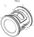
FIG. 4 is a diagram illustrating a specific example 2 of the external view of the electromagnetic flow meter according to an embodiment; -
FIG. 5 is a diagram illustrating a specific example of the external view of a return magnetic-path cover of the electromagnetic flow meter according to an embodiment; -
FIG. 6 is a diagram illustrating specific example 1 of the external view of a return magnetic-path sheet of the electromagnetic flow meter according to an embodiment; -
FIG. 7 is a diagram illustrating specific example 2 of the external view of a return magnetic-path sheet of the electromagnetic flow meter according to an embodiment; and -
FIG. 8 is a diagram illustrating specific example 3 of the external view of a return magnetic-path sheet of the electromagnetic flow meter according to an embodiment. - Hereinafter, an electromagnetic flow meter according to an embodiment of the present invention will be explained in detail with reference to the drawings. The present invention is not limited to the embodiment explained below.
- Hereinafter, an overview of an
electromagnetic flow meter 10, a configuration and a function of theelectromagnetic flow meter 10 according to an embodiment will be sequentially explained, and an effect of the embodiment will be explained finally. - The overview of the
electromagnetic flow meter 10 according to the embodiment will be explained usingFIG. 1 andFIG. 2 .FIG. 1 is a diagram illustrating an example of a cross-section in a direction perpendicular to a tube axis of theelectromagnetic flow meter 10 according to the embodiment.FIG. 2 is a diagram illustrating an example of a cross-section in a direction parallel to the tube axis of theelectromagnetic flow meter 10 according to the embodiment. In the following, a basic configuration example of theelectromagnetic flow meter 10 and an effect of theelectromagnetic flow meter 10 will be explained. - As illustrated in
FIG. 1 andFIG. 2 , theelectromagnetic flow meter 10 includes ameasuring tube 1, alining material 2, anexcitation coil 3, anelectrode 5, a returnmagnetic path 6, a return magnetic-path cover 7, a return magnetic-path sheet 8, and afixing member 9. Moreover, theelectromagnetic flow meter 10 measures the flow rate of aconductive fluid 4 flowing inside themeasuring tube 1. - The
electromagnetic flow meter 10 is a measuring device used to measure a flow rate of aconductive fluid 4 such as tap water. Themeasuring tube 1 is made of a non-magnetic metal with corrosion resistance, such as austenitic stainless steel. Thelining material 2 is an insulator that covers an inner tube surface of themeasuring tube 1. A pair of the excitation coils 3 (3a, 3b) are arranged at a position perpendicular to a tube axis, which corresponds to an upper portion and a bottom portion of themeasuring tube 1, and generate a magnetic field inside themeasuring tube 1. Moreover, a pair of the electrodes 5 (5a, 5b) are arranged at a position in a direction perpendicular to the tube axis of themeasuring tube 1 and perpendicular to the arrangement position of theexcitation coils 3. When a flow velocity occurs in theconductive fluid 4 inside themeasuring tube 1 due to Faraday's law of electromagnetic induction, an electromotive force is generated in the direction perpendicular to the magnetic field generated by theexcitation coil 3 and in the direction perpendicular to the tube axis. Theelectromagnetic flow meter 10 detects the generated electromotive force with the electrodes 5 (5a, 5b), and converts it to a flow rate of theconductive fluid 4. - The return
magnetic path 6 has a function of concentrating the magnetic field generated by theexcitation coil 3 to the inside of themeasuring tube 1 including theelectrodes 5, and is constituted of a ferromagnetic material such as silicon steel plate. Theelectromagnetic flow meter 10 includes at least one of the return magnetic-path cover 7 and the return magnetic-path sheet 8 as a return magnetic-path auxiliary member that complements the properties of the returnmagnetic path 6. - The return magnetic-
path cover 7 has a first function as a magnetic shield that confines the magnetic field generated by the excitation coil, and a second function of reinforcing the magnetic field in a central portion of theexcitation coil 3 as an electromagnet. The return magnetic-path cover 7 is arranged to cover theexcitation coils 3 and a side surface in a circumferential direction of the tube axis of the returnmagnetic path 6. Moreover, particularly as illustrated inFIG. 2 , it has a shape entering inside (inwardly extending into) a gap of theexcitation coil 3. - The return magnetic-
path cover 7 has a first function of shielding such that the magnetic field generated by theexcitation coil 3 is not to leak outside, arranged on a side surface in a circumferential direction of a tube axis. Moreover, the return magnetic-path cover 7 has a second function of reinforcing the magnetic field generated by theexcitation coil 3 as an electromagnet with its shape extending inwardly to the inside of the gap of theexcitation coil 3. In this case, the return magnetic-path cover 7 is fixed to overlap with the returnmagnetic path 6 in the direction perpendicular to the tube axis inside the gap of theexcitation coil 3 by afixing member 9, and the magnetic field is further reinforced as an electromagnet by increasing the volume of the ferromagnetic material inside the gap of theexcitation coil 3. - If the return magnetic-
path cover 7 is to be manufactured as a component integrated with the returnmagnetic path 6, extensive bending process is necessary, making it technically difficult and increasing the manufacturing cost significantly. Moreover, in theexcitation coil 3, as a plate thickness inside the gap of theexcitation coil 3 increases, the effect as the electromagnet increases to reinforce the magnetic field. However, an external portion of theexcitation coil 3 does not require such a thick plate as a magnetic shield, and it becomes an unnecessary use of material. On the other hand, by separating the returnmagnetic path 6 and the return magnetic-path cover 7 into two parts, it is possible to design it to be thick (double layer) inside the gap of theexcitation coil 3 at which the two parts overlap with each other, and to be thin (single layer), on the other hand, because there are no overlapping parts on the outside of theexcitation coil 3. Accordingly, it is possible to form the high-performance returnmagnetic path 6 at a relatively low material cost. - The return magnetic-
path sheet 8 has a first function of absorbing the magnetic field generated by the excitation coil, and a second function of reinforcing the magnetic field of a central portion of theexcitation coil 3 as an electromagnet. The return magnetic-path sheet 8 has a slit that is cut avoiding portions directly beneath theexcitation coil 3, and has a shape to cover the inner portion of the gap on a bottom surface (grounding surface) of theexcitation coil 3 and peripheral portions on the bottom surface of theexcitation coil 3. - The return magnetic-
path sheet 8 prevents the magnetic field generated by theexcitation coil 3 from being drawn toward the counterpart piping by being arranged at the peripheral portions on the bottom surface of theexcitation coil 3. In this case, the return magnetic-path sheet 8 exerts the first function of absorbing the magnetic flux of the magnetic field generated by theexcitation coil 3. Moreover, the return magnetic-path sheet 8 exerts the second function of reinforcing the magnetic field generated by theexcitation coil 3 as an electromagnet by being arranged inside the gap on the bottom surface of theexcitation coil 3. - Moreover, because the return magnetic-
path sheet 8 has the slit so as to avoid the portion directly beneath theexcitation coil 3, it does not interfere a flow of the magnetic field generated by theexcitation coil 3 to a flow path of themeasuring tube 1. The return magnetic-path sheet 8 is only required to have a hollow directly beneath the bottom surface of theexcitation coil 3, and to fill other portions, which are the inside of the gap on the bottom surface of theexcitation coil 3 and the peripheral portion on the bottom surface of theexcitation coil 3, with ferromagnetic material. - In the following, after explaining an overview and a problem of a reference technique, an effect of the
electromagnetic flow meter 10 will be explained. - First, the summary of
Reference Technique 1 realizing an inexpensive wafer-type electromagnetic flow meter that reduces leakage magnetic flux and reduces an influence of a material of a counterpart piping will be explained.Reference Technique 1 is a wafer-type electromagnetic flow meter equipped with a mini flange, and is an electromagnetic flow meter including a shielding plate made of magnetic material that is arranged on a flange portion parallel to a plane of the mini flange, and that shields leakage of magnetic flux in a direction of a flow of a measurement fluid from an excitation coil. - Second, an overview of
Reference Technique 2 that prevents a measurement error when connecting two ferromagnetic iron pipes to a measuring tube will be explained.Reference Technique 2 is an electromagnetic flow meter that includes a coil serving as a magnetic field generating means generating a magnetic field orthogonal to a flow of a measurement fluid in a measuring tube, at least a pair of electrodes arranged to face each other on a diameter of the measuring tube to measure an electromotive force generated by an action of the magnetic field, and magnetic shielding plates that are arranged to be flanges at both ends of the measuring tube having a small influence to the magnetic field. - Third, an overview of
Reference Technique 3 that provides a magnetic circuit having high shielding properties, that prevents leakage of magnetic flux in an axial direction of a measurement tube, and that contributes to reduction of a distance between short sides will be explained.Reference Technique 3 is an electromagnetic flow-rate detector in which a high-permeability magnetic metal ring positioned at an outer end of a measuring tube and a concentric high-permeability side magnetic path are integrated into a single cast structure. - First,
Related technique 1 andRelated technique 2 are techniques in which a portion at a position distant from the excitation coil is shielded. However, a gap between a return magnetic path and a magnetic shield is large, and it is difficult to efficiently suppress leakage of magnetic flux from the excitation coil to a counterpart piping. - Second, in
Reference Technique 3, when an iron-based ferromagnetic material is used as a material for the magnetic shield of the electromagnetic flow meter considering cost and the like, the ion-based material cannot be directly exposed to fluids or external environments because it is significantly inferior in corrosion resistance, and strong rust can form as a result of reacting with a lining material, such as Perfluoroalkoxy alkane (PFA), that is injection-molded onto an inner wall of a pipe in the electromagnetic flow meter. On the other hand, inReference Technique 3, when austenitic stainless steel, which has high corrosion resistance, is used for the detector, and an iron-based material is used as the magnetic shield at a part of the interior of the detector, the same problem as those inReference Technique 1 andReference Technique 2 described above arises. - The
electromagnetic flow meter 10 according to the embodiment optimizes the structure and the shape of the returnmagnetic path 6, and at least one of the return magnetic-path cover 7 and the return magnetic-path sheet 8 is equipped as a return magnetic-path auxiliary member that complements the properties of the returnmagnetic path 6, thereby improving the magnetic shield properties without significant cost increase, and improving the return efficiency of the magnetic flux in a flow path portion. That is, theelectromagnetic flow meter 10 can improve the measuring accuracy. - A configuration and a function of the
electromagnetic flow meter 10 illustrated inFIG. 1 andFIG. 2 will be explained usingFIG. 3 to FIG. 8 . Theelectromagnetic flow meter 10 measures a flow rate of theconductive fluid 4 flowing through the measuringtube 1.FIG. 3 andFIG. 4 are diagrams illustrating a specific example of an external view of theelectromagnetic flow meter 10 according to the embodiment.FIG. 5 is a diagram illustrating a specific example an external view of the return magnetic-path cover 7 of theelectromagnetic flow meter 10 according to the embodiment.FIG. 6 to FIG. 8 are diagrams illustrating a specific example of an external view of the return magnetic-path sheet 8 of theelectromagnetic flow meter 10 according to the embodiment. In the following, the configuration example and the function example of theelectromagnetic flow meter 10 will be explained in detail in order of the measuringtube 1, thelining material 2, theexcitation coil 3, theelectrode 5, the returnmagnetic path 6, the return magnetic-path cover 7, the return magnetic-path sheet 8, and the fixingmember 9. - A configuration example and a function example of the measuring
tube 1 will be explained usingFIG. 3 andFIG. 4 . The measuringtube 1 is arranged in a counterpart pipe in which theconductive fluid 4 to be measured flows, and is a tube in a cylindrical shape forming a flow path of theconductive fluid 4. Moreover, the measuringtube 1 is constituted of a non-magnetic metal having corrosion resistance, such as austenitic stainless steel. - A configuration example and a function example of the
lining material 2 will be explained usingFIG. 3 andFIG. 4 . Thelining material 2 is an insulating material that covers an inner portion in a tube of the measuringtube 1. For example, thelining material 2 is constituted of an insulating material, such as PFA, that is injection molded onto an inner wall inside the tubular path of the measuringtube 1. - A configuration example and a function example of the
excitation coil 3 will be explained usingFIG. 3 andFIG. 4 . Theexcitation coil 3 is arranged in the measuringtube 1, and generates a magnetic field in a direction perpendicular to the tube axis of the measuringtube 1. In this case, theexcitation coil 3 is arranged on an outer diameter side in the direction perpendicular to the tube axis of the measuringtube 1 as a pair of theexcitation coil 3a and theexcitation coil 3b facing each other, and generates a magnetic field in the measuringtube 1 between the pair of theexcitation coil 3a and theexcitation coil 3b. - A configuration example and a function example of the
electrode 5 will be explained usingFIG. 3 andFIG. 4 . Theelectrode 5 is arranged in the measuringtube 1. It is arranged in the perpendicular position to the tube axis of the measuringtube 1 at a position perpendicular to an installation position of theexcitation coil 3, and detects an electromotive force generated as theconductive fluid 4 flows inside the measuringtube 1. In this case, theelectrode 5 is arranged as a pair of theelectrode 5a and theelectrode 5b facing each other on the outer diameter side in the direction perpendicular to the tube axis of the measuringtube 1, and detects a signal of an electromotive force that is generated in a direction perpendicular to the tube axis, and that is proportional to a flow rate of theconductive fluid 4 flowing inside the measuringtube 1. - A configuration example and a function example of the return
magnetic path 6 will be explained usingFIG. 3 andFIG. 4 . The returnmagnetic path 6 is a circuit that applies a magnetic field in a direction perpendicular to the flow path of theconductive fluid 4, and is arranged on a side surface in the circumferential direction of the tube axis including theexcitation coil 3 in the measuringtube 1, and concentrates the magnetic field generated by theexcitation coil 3 to the inside of the measuringtube 1. The returnmagnetic path 6 may be arranged on a side surface in the circumferential direction of a tube axis including all of a pair of the excitation coils 3 (3a, 3b) and a pair of the electrodes 5 (5a, 5b) in the measuringtube 1. Moreover, the returnmagnetic path 6 is a ferromagnetic plate. For example, the returnmagnetic path 6 is constituted of a silicon steel plate. - A configuration example and a function example of the return magnetic-
path cover 7 will be explained usingFIG. 3 to FIG. 5 . The return magnetic-path cover 7 is arranged on at least one of an outer diameter side and an inner diameter side in the direction perpendicular to the tube axis of theexcitation coil 3, and is one of the return magnetic-path auxiliary members that complements the function of the returnmagnetic path 6. For example, the return magnetic-path cover 7 is arranged on the outer diameter side in the direction perpendicular to the tube axis of theexcitation coil 3, and blocks movement of a magnetic flux toward the outer diameter side. Furthermore, the return magnetic-path cover 7 is arranged to extend inwardly to the gap of theexcitation coil 3 on the outer diameter side in the direction perpendicular to the tube axis of theexcitation coil 3, to reinforce the magnetic field generated by theexcitation coil 3. Moreover, the return magnetic-path cover 7 is a plate of a ferromagnetic material. - A specific example of the return magnetic-
path cover 7 will be explained usingFIG. 5 . As illustrated inFIG. 5 , the return magnetic-path cover 7 has a structure extending inwardly to the gap of theexcitation coil 3 on the outer diameter side in the direction perpendicular to the tube axis of theexcitation coil 3. In the example inFIG. 5 , the return magnetic-path cover 7 has a separable structure so as to be arranged to cover either one out of a pair of theexcitation coil 3a and theexcitation coil 3b. That is, the return magnetic-path cover 7 illustrated in the example inFIG. 5 is arranged to cover both of a pair of theexcitation coil 3a and theexcitation coil 3b using two sets. Moreover, although the return magnetic-path cover 7 illustrated inFIG. 5 has a separable structure so that installation is easy, it may be structured with a combined single part. The return magnetic-path cover 7 may have a structure to be arranged to cover all of a pair of theexcitation coil 3a and theexcitation coil 3b with a single part. - As described above, the return magnetic-
path cover 7 exerts the first function of blocking the magnetic field generated by theexcitation coil 3 to prevent external leakage by being arranged on the side surface in the circumferential direction of a tube axis. Moreover, the return magnetic-path cover 7 exerts the second function of reinforcing the magnetic field generated by theexcitation coil 3 as an electromagnet with the shape extending inwardly to the inside of the gap of theexcitation coil 3. - A configuration example and a function example of the return magnetic-
path sheet 8 is will be explained usingFIG. 3 to FIG. 8 . The return magnetic-path sheet 8 is arranged on at least one of the outer diameter side and the inner diameter side in the direction perpendicular to the tube axis of theexcitation coil 3, and is one of the return magnetic-path auxiliary member that complements the function of the returnmagnetic path 6. For example, the return magnetic-path sheet 8 is arranged on the inner diameter side in the direction perpendicular to the tube axis of theexcitation coil 3, and absorbs the magnetic flux of the magnetic field toward the outer diameter side in the direction perpendicular to the tube axis of theexcitation coil 3. Moreover, the return magnetic-path sheet 8 is arranged on the inner diameter side in the direction perpendicular to the tube axis of theexcitation coil 3 except a position at which the measuringtube 1 is arranged, and passes the magnetic flux of the magnetic field toward the inner diameter side, and reinforces the magnetic field generated by theexcitation coil 3. Furthermore, the return magnetic-path sheet 8 is a plate of a ferromagnetic material. - A specific example of the return magnetic-path sheet 8 (8-1, 8-2, 8-3) will be explained using
FIG. 6 to FIG. 8 . As illustrated inFIG. 6 to FIG. 8 , the return magnetic-path sheet 8 has a structure that is arranged on the inner diameter side in the direction perpendicular to the tube axis of theexcitation coil 3. In this case, the return magnetic-path sheet 8 is only required to have a structure not obstructing the flow of the magnetic field into the flow path of the measuringtube 1, and to fill other portions, which is the inside of the gap on the bottom surface of theexcitation coil 3 and the peripheral portion on the bottom surface of theexcitation coil 3, with a ferromagnetic material. - In the example in
FIG. 6 , the return magnetic-path sheet 8-1 has a structure separated into three parts, to avoid being located directly beneath theexcitation coil 3, and to cover the inside of the gap and the peripheral portions on the bottom surface of theexcitation coil 3. - In the example in
FIG. 7 , the return magnetic-path sheet 8-2 has a structure in which four slits are formed, to avoid being located directly beneath theexcitation coil 3, and to cover the inside of the gap and the peripheral portions on the bottom surface of theexcitation coil 3. - In the example in
FIG. 8 , the return magnetic-path sheet 8-3 has a structure in which two hollows are formed, to avoid being located directly beneath theexcitation coil 3, and to cover the inside of the gap and the peripheral portions on the bottom surface of theexcitation coil 3. - As described above, the return magnetic-
path sheet 8 exerts the first function of absorbing the magnetic flux of the magnetic field generated by theexcitation coil 3 by being arranged in the peripheral portions on the bottom surface of theexcitation coil 3. Moreover, the return magnetic-path sheet 8 exerts the second function of reinforcing the magnetic field generated by theexcitation coil 3 as an electromagnet by being arranged in the inside of the gap on the bottom surface of theexcitation coil 3. - A configuration example and a function example of the fixing
member 9 will be explained usingFIG. 3 andFIG. 4 . The fixingmember 9 fixes the returnmagnetic path 6, the return magnetic-path cover 7, and the return magnetic-path sheet 8. In the example inFIG. 3 andFIG. 4 , the fixingmember 9 is constituted of two parts, but the number of parts of the fixingmember 9 is not particularly limited. - Finally, an effect of the embodiment will be explained. In the following,
effects 1 to 6 corresponding to the configurations and functions according to the embodiment will be explained. - First, in the embodiment described above, the
electromagnetic flow meter 10 includes theexcitation coil 3 that is arranged in the measuringtube 1, and that generates a magnetic field in the direction perpendicular to the tube axis of the measuringtube 1, a returnmagnetic path 6 that is arranged on the side surface in the circumferential direction of a tube axis including theexcitation coil 3, and that concentrates the magnetic field generated by theexcitation coil 3 to the inside of the measuringtube 1, and the return magnetic-path auxiliary member that is arranged at least one of the outer diameter side and the inner diameter side in the direction perpendicular to the tube axis of theexcitation coil 3, and that complements the function of the returnmagnetic path 6. Therefore, according to the embodiment, the measuring accuracy of theelectromagnetic flow meter 10 can be improved. - Second, in the embodiment described above, the
electromagnetic flow meter 10 has the return magnetic-path cover 7 that is the return magnetic-path auxiliary member arranged on the outer diameter side in the direction perpendicular to the tube axis of theexcitation coil 3, to block the movement of the magnetic flux of the magnetic field toward the outer diameter side. Therefore, according to the embodiment, by suppressing leakage of the magnetic flux to the outside with the return magnetic-path cover 7, the measuring accuracy of theelectromagnetic flow meter 10 can be improved. - Third, in the embodiment described above, the return magnetic-
path cover 7 that is the return magnetic-path auxiliary member is arranged to extend inwardly to the gap of theexcitation coil 3, and reinforces the magnetic field generated byexcitation coil 3. Therefore, according to the embodiment, by reinforcing the magnetic field in a central portion of theexcitation coil 3 with the return magnetic-path cover 7 as an electromagnet, the measuring accuracy of theelectromagnetic flow meter 10 can be improved. - Fourth, in the embodiment described above, the
electromagnetic flow meter 10 has the return magnetic-path sheet 8 that is the return magnetic-path auxiliary member on the inner diameter side in the direction perpendicular to the tube axis of theexcitation coil 3, to absorb the magnetic flux of the magnetic field to the outer diameter side. Therefore, according to the embodiment, by suppressing the leakage of the magnetic flux to the outside with the return magnetic-path sheet 8, the measuring accuracy of theelectromagnetic flow meter 10 can be improved. - Fifth, in the embodiment described above, the
electromagnetic flow meter 10 has the return magnetic-path sheet 8 that is the return magnetic-path auxiliary member arranged on the inner diameter side except the position at which theexcitation coil 3 is arranged in the measuringtube 1, and that passes the magnetic flux of the magnetic field to the inner diameter side, to reinforce the magnetic field generated byexcitation coil 3. Therefore, according to the embodiment, by reinforcing the magnetic field of a central portion of theexcitation coil 3 with the return magnetic-path sheet 8 as an electromagnet such that the flow of the magnetic field to the flow path of the measuringtube 1 is not interfered, the measuring accuracy of theelectromagnetic flow meter 10 can be improved. - Sixth, according to the above embodiment, in the
electromagnetic flow meter 10, at least one of the return magnetic-path cover 7 and the return magnetic-path sheet 8, which are the return magnetic-path auxiliary member, is a plate of a ferromagnetic material. Therefore, according to the embodiment, by effectively complementing the function of the returnmagnetic path 6 with the return magnetic-path auxiliary member, the measuring accuracy of theelectromagnetic flow meter 10 can be improved. - The processing procedure, the control procedure, the specific names, and the information including various kinds of data and parameters described in the above documents and the drawings can be arbitrarily changed unless otherwise specified.
- Moreover, the respective components of the respective devices illustrated are of functional concept, and it is not necessarily required to be configured physically as illustrated. That is, specific forms of distribution and integration of the respective devices are not limited to the ones illustrated. That is, all or some thereof can be configured to be distributed or integrated functionally or physically in arbitrary units according to various kinds of loads, usage conditions, and the like.
- According to the present invention, there is an effect of improving the measurement accuracy of an electromagnetic flow meter.
Claims (6)
- An electromagnetic flow meter (10) that measures a flow rate of a conductive fluid flowing through a measuring tube (1), comprising:an excitation coil (3) that is arranged in the measuring tube (1), and that generates a magnetic field in a direction perpendicular to a tube axis of the measuring tube (1);a return magnetic path (6) that is arranged on a side surface in a circumferential direction of a tube axis including the excitation coil (3) in the measuring tube (1), and that concentrates the magnetic field generated by the excitation coil (3) to an inside of the measuring tube (1); anda return magnetic-path auxiliary member that is arranged on at least one of an outer diameter side and an inner diameter side in the direction perpendicular to the tube axis of the excitation coil, and that complements a function of the return magnetic path (6).
- The electromagnetic flow meter (10) according to claim 1, wherein
the return magnetic-path auxiliary member is arranged on the outer diameter side in the direction perpendicular to the tube axis of the excitation coil (3), and blocks movement of a magnetic flux of the magnetic field to the outer diameter side. - The electromagnetic flow meter (10) according to claim 2, wherein
the return magnetic-path auxiliary member is arranged to extend inwardly to a gap of the excitation coil (3), and reinforces the magnetic field generated by the excitation coil (3). - The electromagnetic flow meter (10) according to any one of claims 1 to 3, wherein
the return magnetic-path auxiliary member is arranged on the inner diameter side in the direction perpendicular to the tube axis of the excitation coil (3), and absorbs a magnetic flux of the magnetic field toward the outer diameter side. - The electromagnetic flow meter (10) according to claim 4, wherein
the return magnetic-path auxiliary member is arranged on the inner diameter side except a position at which the excitation coil (3) is arranged in the measuring tube (1), and passes a magnetic flux of the magnetic field toward the inner diameter side, and reinforces the magnetic field generated by the excitation coil (3). - The electromagnetic flow meter (10) according to any one of claims 1 to 5, wherein the return magnetic-path auxiliary member is a plate of a ferromagnetic material.
Applications Claiming Priority (1)
| Application Number | Priority Date | Filing Date | Title |
|---|---|---|---|
| JP2023183969A JP2025073311A (en) | 2023-10-26 | 2023-10-26 | electromagnetic flow meter |
Publications (1)
| Publication Number | Publication Date |
|---|---|
| EP4545914A1 true EP4545914A1 (en) | 2025-04-30 |
Family
ID=93257652
Family Applications (1)
| Application Number | Title | Priority Date | Filing Date |
|---|---|---|---|
| EP24208008.3A Pending EP4545914A1 (en) | 2023-10-26 | 2024-10-22 | ELECTROMAGNETIC FLOW METER |
Country Status (4)
| Country | Link |
|---|---|
| US (1) | US20250137824A1 (en) |
| EP (1) | EP4545914A1 (en) |
| JP (1) | JP2025073311A (en) |
| CN (1) | CN119901343A (en) |
Citations (7)
| Publication number | Priority date | Publication date | Assignee | Title |
|---|---|---|---|---|
| EP0069459A1 (en) * | 1981-06-05 | 1983-01-12 | Aichi Tokei Denki Co., Ltd. | Measuring device of electromagnetic flowmeter |
| JPH02143120A (en) * | 1988-11-25 | 1990-06-01 | Toshiba Corp | Electromagnetic flowmeter |
| JPH05256674A (en) | 1992-03-16 | 1993-10-05 | Hitachi Ltd | Electromagnetic flowmeter detector |
| JPH09145435A (en) | 1995-11-22 | 1997-06-06 | Yamatake Honeywell Co Ltd | Electromagnetic flow meter |
| JP2001116598A (en) * | 1999-10-19 | 2001-04-27 | Yokogawa Electric Corp | Capacitive electromagnetic flowmeter |
| US20050000300A1 (en) * | 2003-05-15 | 2005-01-06 | Thomas Zingg | Electromagnetic flow sensor |
| JP2005172645A (en) | 2003-12-12 | 2005-06-30 | Yokogawa Electric Corp | Wafer type electromagnetic flow meter |
-
2023
- 2023-10-26 JP JP2023183969A patent/JP2025073311A/en active Pending
-
2024
- 2024-10-17 CN CN202411453787.7A patent/CN119901343A/en active Pending
- 2024-10-18 US US18/920,473 patent/US20250137824A1/en active Pending
- 2024-10-22 EP EP24208008.3A patent/EP4545914A1/en active Pending
Patent Citations (7)
| Publication number | Priority date | Publication date | Assignee | Title |
|---|---|---|---|---|
| EP0069459A1 (en) * | 1981-06-05 | 1983-01-12 | Aichi Tokei Denki Co., Ltd. | Measuring device of electromagnetic flowmeter |
| JPH02143120A (en) * | 1988-11-25 | 1990-06-01 | Toshiba Corp | Electromagnetic flowmeter |
| JPH05256674A (en) | 1992-03-16 | 1993-10-05 | Hitachi Ltd | Electromagnetic flowmeter detector |
| JPH09145435A (en) | 1995-11-22 | 1997-06-06 | Yamatake Honeywell Co Ltd | Electromagnetic flow meter |
| JP2001116598A (en) * | 1999-10-19 | 2001-04-27 | Yokogawa Electric Corp | Capacitive electromagnetic flowmeter |
| US20050000300A1 (en) * | 2003-05-15 | 2005-01-06 | Thomas Zingg | Electromagnetic flow sensor |
| JP2005172645A (en) | 2003-12-12 | 2005-06-30 | Yokogawa Electric Corp | Wafer type electromagnetic flow meter |
Also Published As
| Publication number | Publication date |
|---|---|
| CN119901343A (en) | 2025-04-29 |
| JP2025073311A (en) | 2025-05-13 |
| US20250137824A1 (en) | 2025-05-01 |
Similar Documents
| Publication | Publication Date | Title |
|---|---|---|
| KR930007156B1 (en) | Electromagnetic flowmeter | |
| CN104823027A (en) | Magnetically inductive flow meter | |
| US9709426B2 (en) | Magnetic-inductive flowmeter | |
| CN103575342B (en) | Electromagnetic Induction Flow Meter | |
| US11473948B2 (en) | Magnetically inductive flowmeter including a coil system having means for field guide-back | |
| KR100584890B1 (en) | Electromagnetic Flowmeter | |
| US3610040A (en) | Electromagnetic flowmeter | |
| CN110319898A (en) | A kind of Retarder electrical switching device and method | |
| US8037774B2 (en) | State detection device | |
| US4186600A (en) | Magnet system for electromagnetic flowmeter | |
| CN100424478C (en) | Magnetic induction flow sensor | |
| US20120047987A1 (en) | Electromagnetic flow rate measurement system and calibrator therefor | |
| CN105157767A (en) | Electromagnetic flow transducer | |
| US2734380A (en) | mittelmann | |
| US3372589A (en) | Side-saddle magnetic flowmeter | |
| US20250137824A1 (en) | Electromagnetic flow meter | |
| CN103988054A (en) | Coil system of a magnetically inductive flow meter | |
| CN120102416A (en) | A multi-channel detection device for oil wear particles based on Helmholtz coil | |
| US20070034015A1 (en) | Electromagnetic flowmeter | |
| EP3628982B1 (en) | Full bore magnetic flowmeter assembly | |
| JPH03205513A (en) | Detector of electromagnetic flow meter | |
| JPH0226029Y2 (en) | ||
| JP2025073312A (en) | electromagnetic flow meter | |
| JP6428040B2 (en) | Excitation device and mass flow meter | |
| CN211602045U (en) | Plug-in electromagnetic flowmeter |
Legal Events
| Date | Code | Title | Description |
|---|---|---|---|
| PUAI | Public reference made under article 153(3) epc to a published international application that has entered the european phase |
Free format text: ORIGINAL CODE: 0009012 |
|
| STAA | Information on the status of an ep patent application or granted ep patent |
Free format text: STATUS: THE APPLICATION HAS BEEN PUBLISHED |
|
| AK | Designated contracting states |
Kind code of ref document: A1 Designated state(s): AL AT BE BG CH CY CZ DE DK EE ES FI FR GB GR HR HU IE IS IT LI LT LU LV MC ME MK MT NL NO PL PT RO RS SE SI SK SM TR |
|
| STAA | Information on the status of an ep patent application or granted ep patent |
Free format text: STATUS: REQUEST FOR EXAMINATION WAS MADE |
|
| 17P | Request for examination filed |
Effective date: 20251029 |