EP4545879A1 - Chiller - Google Patents
Chiller Download PDFInfo
- Publication number
- EP4545879A1 EP4545879A1 EP24208355.8A EP24208355A EP4545879A1 EP 4545879 A1 EP4545879 A1 EP 4545879A1 EP 24208355 A EP24208355 A EP 24208355A EP 4545879 A1 EP4545879 A1 EP 4545879A1
- Authority
- EP
- European Patent Office
- Prior art keywords
- discharge pipe
- valve plate
- compressor
- wall
- chiller
- Prior art date
- Legal status (The legal status is an assumption and is not a legal conclusion. Google has not performed a legal analysis and makes no representation as to the accuracy of the status listed.)
- Pending
Links
Images




Classifications
-
- F—MECHANICAL ENGINEERING; LIGHTING; HEATING; WEAPONS; BLASTING
- F25—REFRIGERATION OR COOLING; COMBINED HEATING AND REFRIGERATION SYSTEMS; HEAT PUMP SYSTEMS; MANUFACTURE OR STORAGE OF ICE; LIQUEFACTION SOLIDIFICATION OF GASES
- F25B—REFRIGERATION MACHINES, PLANTS OR SYSTEMS; COMBINED HEATING AND REFRIGERATION SYSTEMS; HEAT PUMP SYSTEMS
- F25B1/00—Compression machines, plants or systems with non-reversible cycle
- F25B1/04—Compression machines, plants or systems with non-reversible cycle with compressor of rotary type
-
- F—MECHANICAL ENGINEERING; LIGHTING; HEATING; WEAPONS; BLASTING
- F25—REFRIGERATION OR COOLING; COMBINED HEATING AND REFRIGERATION SYSTEMS; HEAT PUMP SYSTEMS; MANUFACTURE OR STORAGE OF ICE; LIQUEFACTION SOLIDIFICATION OF GASES
- F25B—REFRIGERATION MACHINES, PLANTS OR SYSTEMS; COMBINED HEATING AND REFRIGERATION SYSTEMS; HEAT PUMP SYSTEMS
- F25B49/00—Arrangement or mounting of control or safety devices
- F25B49/02—Arrangement or mounting of control or safety devices for compression type machines, plants or systems
-
- F—MECHANICAL ENGINEERING; LIGHTING; HEATING; WEAPONS; BLASTING
- F25—REFRIGERATION OR COOLING; COMBINED HEATING AND REFRIGERATION SYSTEMS; HEAT PUMP SYSTEMS; MANUFACTURE OR STORAGE OF ICE; LIQUEFACTION SOLIDIFICATION OF GASES
- F25B—REFRIGERATION MACHINES, PLANTS OR SYSTEMS; COMBINED HEATING AND REFRIGERATION SYSTEMS; HEAT PUMP SYSTEMS
- F25B31/00—Compressor arrangements
-
- F—MECHANICAL ENGINEERING; LIGHTING; HEATING; WEAPONS; BLASTING
- F25—REFRIGERATION OR COOLING; COMBINED HEATING AND REFRIGERATION SYSTEMS; HEAT PUMP SYSTEMS; MANUFACTURE OR STORAGE OF ICE; LIQUEFACTION SOLIDIFICATION OF GASES
- F25B—REFRIGERATION MACHINES, PLANTS OR SYSTEMS; COMBINED HEATING AND REFRIGERATION SYSTEMS; HEAT PUMP SYSTEMS
- F25B39/00—Evaporators; Condensers
- F25B39/04—Condensers
-
- F—MECHANICAL ENGINEERING; LIGHTING; HEATING; WEAPONS; BLASTING
- F25—REFRIGERATION OR COOLING; COMBINED HEATING AND REFRIGERATION SYSTEMS; HEAT PUMP SYSTEMS; MANUFACTURE OR STORAGE OF ICE; LIQUEFACTION SOLIDIFICATION OF GASES
- F25B—REFRIGERATION MACHINES, PLANTS OR SYSTEMS; COMBINED HEATING AND REFRIGERATION SYSTEMS; HEAT PUMP SYSTEMS
- F25B41/00—Fluid-circulation arrangements
- F25B41/20—Disposition of valves, e.g. of on-off valves or flow control valves
-
- F—MECHANICAL ENGINEERING; LIGHTING; HEATING; WEAPONS; BLASTING
- F25—REFRIGERATION OR COOLING; COMBINED HEATING AND REFRIGERATION SYSTEMS; HEAT PUMP SYSTEMS; MANUFACTURE OR STORAGE OF ICE; LIQUEFACTION SOLIDIFICATION OF GASES
- F25B—REFRIGERATION MACHINES, PLANTS OR SYSTEMS; COMBINED HEATING AND REFRIGERATION SYSTEMS; HEAT PUMP SYSTEMS
- F25B2400/00—Component parts or details not otherwise provided for in this subclass
- F25B2400/07—Details of compressors or related parts
-
- F—MECHANICAL ENGINEERING; LIGHTING; HEATING; WEAPONS; BLASTING
- F25—REFRIGERATION OR COOLING; COMBINED HEATING AND REFRIGERATION SYSTEMS; HEAT PUMP SYSTEMS; MANUFACTURE OR STORAGE OF ICE; LIQUEFACTION SOLIDIFICATION OF GASES
- F25B—REFRIGERATION MACHINES, PLANTS OR SYSTEMS; COMBINED HEATING AND REFRIGERATION SYSTEMS; HEAT PUMP SYSTEMS
- F25B2500/00—Problems to be solved
- F25B2500/28—Means for preventing liquid refrigerant entering into the compressor
Definitions
- the invention relates to the technical field of air conditioners, in particular to a chiller.
- a refrigerant When a chiller of a heating, ventilation, and air conditioning system operates normally, a refrigerant is compressed by a compressor and then discharged into a condenser from an outlet of the compressor through a discharge pipe. When the chiller is shut down unexpectedly, the uncondensed refrigerant may flow back into the compressor through the discharge pipe, which brings a risk to the stability of a bearing component and a rotating shaft of the compressor, thereby affecting the subsequent normal operation of the chiller.
- a common solution is to install a spring-loaded check valve in the discharge pipe.
- a maximum opening of the spring-loaded check valve is usually 45 degrees, which may hinder the normal discharge of the compressor, causing a constant pressure drop (about 1 psi to 2 psi) on two sides of the spring-loaded check valve and affecting the working efficiency of the chiller.
- a spring since a spring is likely to age and be damaged in the working environment at the outlet of the compressor, the reliability of the spring-loaded check valve is greatly limited by the reliability of the spring, which reduces the overall reliability of the chiller and increases maintenance costs.
- a chiller including a compressor and a condenser, in which an outlet of the compressor communicates with an inlet of the condenser through a discharge pipe, a rotating shaft and a valve plate having a counterweight are further disposed in the discharge pipe, the rotating shaft is fixed on an inner wall of the discharge pipe, the valve plate can rotate around the rotating shaft, and a rotatable stroke of the valve plate includes swinging down to a first position to close the discharge pipe, and swinging up to a second position toward a side away from the outlet of the compressor to open the discharge pipe.
- the compressor is disposed above the condenser
- the discharge pipe has a main body section extending in a vertical direction and a bent section formed by bending the main body section laterally, the bent section communicates with the outlet located on a side surface of the compressor, and the rotating shaft and the valve plate are both disposed in the bent section.
- the bent section further includes a horizontal section extending horizontally, and the rotating shaft and the valve plate are disposed in the horizontal section.
- the chiller further includes a limiting portion formed by the inner wall of the discharge pipe extending radially inward and disposed on a side of the valve plate closer to the outlet of the compressor, in which an outer edge of the valve plate at the first position abuts against an inner edge of the limiting portion.
- the limiting portion is an integrally formed limiting plate having a complete outer edge and connected to the inner wall of the discharge pipe over entire circumferential range.
- the limiting portion includes a side plate formed by a side portion of the inner wall of the discharge pipe extending radially inward, and a bottom plate formed by a bottom portion of the inner wall of the discharge pipe extending radially inward, a top portion of the valve plate at the first position abuts against the inner wall of the discharge pipe, a side edge of the valve plate abuts against the side plate, and a lower edge of the valve plate abuts against the bottom plate.
- the limiting portion is elastic.
- the limiting portion is fixed to the inner wall of the discharge pipe by welding.
- the limiting portion is inclined at an angle of 0° to 3° with respect to the vertical direction.
- the compressor is a centrifugal compressor.
- valve plate swings down to the first position only by self weight that provides a driving force.
- the counterweight has a weight of 1 kg to 15 kg.
- the valve plate having the counterweight is rotatably mounted on the rotating shaft.
- the valve plate can rotate about the rotating shaft and swing up to the second position to maintain a large opening.
- the valve plate can also spontaneously adjust the opening in response to a change in a flow rate of a refrigerant, depending on the flow rate of the refrigerant.
- the valve plate can swing down to the first position only under the driving of gravity so as to close the discharge pipe and prevent refrigerant backflow. Since there is no need to provide deformation driving components such as springs and the closing of the valve plate is driven only by gravity, the reliability of the check valve is better, and maintenance costs can be effectively reduced.
- swings down means to swing downward or sideways in the direction of gravity
- swings up means to swing upward or sideways in the direction of gravity
- the valve plate has a "counterweight", which may mean that a valve plate with a heavy weight is used, or additional accessories such as a counterweight block or a counterweight plate may be added and fixed to a main body of the valve plate.
- the weight of the counterweight may be selected as long as a discharge pipe can be normally opened when a compressor is discharged and the discharge pipe can be stably closed when backflow occurs. In some embodiments, the weight of the counterweight may be 2 kg to 15 kg.
- the force acting on a unit flow area is about 1 psi to 10 psi, which can ensure the reliable closing of the discharge pipe.
- the valve plate can also be quickly driven to open.
- FIG. 1 shows an overall diagram of a chiller according to an embodiment of the invention.
- the chiller according to the embodiment of the invention includes a compressor 1 and a condenser 3.
- An outlet 11 of the compressor communicates with an inlet 31 of the condenser through a discharge pipe 2.
- the specific type of the compressor 1 is not limited here.
- the compressor 1 may be a screw compressor, a centrifugal compressor, a scroll compressor, or the like.
- the compressor 1 is a centrifugal compressor.
- the condenser 3 may be a water-cooled condenser, an air-cooled condenser, or the like, preferably a water-cooled condenser.
- the centrifugal compressor uses centrifugal force to drive a refrigerant to discharge from a low-pressure side to a high-pressure side of a system, and the high-pressure refrigerant is discharged from the outlet 11 of the compressor to the condenser 3 through the discharge pipe 2.
- the centrifugal compressor may stop pumping as a pressure difference cannot be overcome, and a "surge" phenomenon may occur.
- the high-temperature and high-pressure refrigerant may flow back along the discharge pipe 2 and impact a bearing component or a rotating shaft of the centrifugal compressor, thereby affecting the subsequent normal operation of the chiller.
- FIG. 2 shows a schematic cross-sectional view of a discharge pipe of the chiller according to the embodiment of the invention.
- the chiller according to the embodiment of the invention further includes a rotating shaft 4 disposed in the discharge pipe 2 and a valve plate 5 having a counterweight.
- the rotating shaft 4 is fixed to an inner wall of the discharge pipe 2, and the valve plate 5 can rotate around the rotating shaft 4 under the action of gravity or a combination of gravity and other driving forces.
- valve plate 5 having a counterweight is rotatably mounted on the rotating shaft 4.
- the compressor 1 continuously discharges a refrigerant into the discharge pipe 2
- the high-temperature and high-pressure refrigerant continuously flows from the outlet 11 of the compressor to the inlet 31 of the condenser
- the valve plate 5 swings up to a side away from the outlet 11 of the compressor under the driving of the refrigerant. Since no spring is provided and there is no restriction of the spring elastic force, the valve plate 5 can rotate to a second position under the driving of a pressure difference on two sides and maintain a large opening. Further, depending on a flow rate of the refrigerant, the driving force of the refrigerant on the valve plate 5 also changes accordingly.
- the opening of the valve plate 5 can spontaneously respond to a change in the flow rate of the refrigerant, thereby avoiding excessive pressure drop of the outlet 11 of the compressor caused by obstruction of the flow of the refrigerant in a discharge pipe 2 and avoiding the loss of pressure heads.
- valve plate 5 When the chiller is normally shut down, that is, there is no refrigerant flowing in the discharge pipe 2, the valve plate 5 can swing down to the first position only by its own gravity to close the discharge pipe 2 and avoid backflow of the high-temperature and high-pressure refrigerant. In a case of unexpected shutdown, if a certain amount of refrigerant flows back, the refrigerant flowing back can further accelerate the downward swing of the valve plate 5, thereby reducing the backflow as much as possible.
- the valve plate 5 and the rotating shaft 4 of the chiller can maintain a large opening when the chiller operates normally, and can spontaneously adjust the opening in response to a change in the flow rate of the refrigerant.
- the reliability of the check valve is better, and maintenance costs can be effectively reduced.
- the valve plate 5 may rotate and swing down to a first position where the valve plate extends in the direction of gravity, or may swing down to a first position inclined to the direction of gravity, as long as the valve plate 5 can stop swinging down and close the discharge pipe 2 in this position.
- the valve plate 5 may be inclined at an angle of 0° to 3° with respect to the direction of gravity.
- the own gravity of the valve plate 5 can be used to set a certain inclination angle, increase the stress between the valve plate 5 and a limiting portion 6, and increase the reliability of the valve plate 5 closing the discharge pipe 2 when the valve plate 5 is in the first position.
- the compressor 1 and the condenser 3 may be disposed according to the actual use environment.
- the compressor 1 and the condenser 3 may be stacked at least partially overlapped in a height direction, the outlet 11 of the compressor and the inlet 31 of the condenser may be disposed on the same side, and two ends of the discharge pipe 2 are bent to respectively communicate with the outlet 11 of the compressor and the inlet 31 of the condenser, so that the internal structure of the chiller is more compact.
- a bent section 21 further includes a horizontal section extending horizontally, and the rotating shaft 4 and the valve plate 5 are disposed in the horizontal section of the discharge pipe 2.
- the valve plate 5 can quickly swing down to abut against a bottom portion of the inner wall of the discharge pipe 2 in the horizontal discharge pipe 2, or can be opened to a position close to, equal to or even exceeding 90° to increase the maximum opening of the discharge pipe 2.
- the compressor 1 is disposed above the condenser 3, and the discharge pipe 2 has a main body section 22 extending in a vertical direction and the bent section 21 formed by bending the main body section 22 laterally.
- an upper portion and a lower portion of the discharge pipe 2 are each formed with the bent section 21.
- An upper bent section 21a communicates with the outlet located on a side surface of the compressor 1, and a lower bent section 21b communicates with the inlet located on a side surface of the condenser 3.
- the compressor 1 and the condenser 3 are stacked up and down to make the internal structure of the chiller more compact.
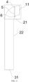
- FIG. 3 shows a schematic structural diagram of the valve plate 5 in the bent section 21 rotating to the first position according to the embodiment of the invention.
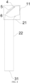
- FIG. 4 shows a schematic structural diagram of the valve plate 5 in the bent section 21 rotating to the second position according to the embodiment of the invention.
- the rotating shaft 4 is fixed to a top portion of an inner wall of the bent section 21, and the valve plate 5 is disposed below the rotating shaft 4 and can rotate around the rotating shaft 4.
- valve plate 5 When the compressor is not operating and no refrigerant flows in the discharge pipe 2, the valve plate 5 rotates to swing down to the first position under the driving of its own gravity.
- the valve plate 5 has a height greater than a diameter of the discharge pipe 2. After the valve plate 5 swings down, a bottom end of the valve plate 5 can directly abut against a bent lower surface of the inner wall of the bent section 21, thereby closing the discharge pipe 2 and blocking the refrigerant flowing back from the condenser 3 if necessary.
- the valve plate 5 When the compressor operates, the refrigerant discharged from the compressor 1 is discharged to the condenser 3 through the discharge pipe 2, and the valve plate 5 is driven by the pressure difference and the flowing refrigerant to swing up to the second position toward the side away from the outlet 11 of the compressor, thereby opening the discharge pipe 2.
- the valve plate 5 When the pressure difference is large enough, the valve plate 5 can be opened until abutting against the top portion of the inner wall of the bent section 21 of the discharge pipe 2, thereby reducing the obstruction to the flow of the refrigerant in the discharge pipe 2 and maintaining smooth flow of the refrigerant in the discharge pipe 2.
- the chiller further includes the limiting portion 6 formed by the inner wall of the discharge pipe 2 extending radially inward.
- the limiting portion 6 is disposed on a side of the valve plate 5 closer to the outlet 11 of the compressor, and an outer edge of the valve plate 5 in the first position abuts against an inner edge of the limiting portion 6.
- the arrangement in which the limiting portion 6 abuts against the valve plate 5 can ensure the reliability of the valve plate 5 closing the discharge pipe 2 in the first position, and prevent the valve plate 5 from swinging in the opposite direction (that is, swinging to the side closer to the outlet of the compressor) under the impact of the refrigerant flowing back.
- the limiting portion 6 may be directly formed by a protrusion on the inner wall of the discharge pipe 2 (as shown in the structure of FIGS. 3 and 4 ), or may be fixedly mounted on the inner wall of the discharge pipe 2.
- an inner diameter of the discharge pipe 2 on the side of the valve plate 5 closer to the outlet 11 of the compressor may be slightly reduced (as shown in FIG. 2 ) to form the limiting portion 6, so that when the valve plate swings down and is closed, the outer edge of the valve plate can abut against the entire circumference of the discharge pipe 2 with a small inner diameter, and the above can be applied to the chiller of the specification.
- the discharge pipe 2 and the limiting portion 6 are both made of metal, and the limiting portion 6 is welded and fixed to the inner wall of the discharge pipe 2, which can increase the reliability and firmness of the limiting portion 6.
- the limiting portion 6 may be an integrally formed limiting plate 61 having a complete outer edge and connected to the inner wall of the discharge pipe 2 over entire circumferential range. Therefore, when the valve plate 5 is in the first position, the outer edge of the entire circumference of the valve plate 5 can abut against the inner edge of the limiting plate 61, so that the discharge pipe 2 can be closed more tightly, and a small amount of refrigerant is prevented from flowing back through a gap between the valve plate 5 and the limiting portion 6.
- the limiting portion 6 may not have a complete outer edge, but one or more limiting plates 61 are disposed at intervals in a circumferential range of the inner wall of the discharge pipe 2.
- the outer edge of the valve plate 5 is in contact with the inner wall of the discharge pipe 2, and the other portion of the valve plate 5 abuts against the limiting plate 61. Since the limiting plate 61 is not connected to the inner wall of the discharge pipe 2 in the entire circumference, the flow of the refrigerant in the discharge pipe 2 is less affected, a maximum flow rate in the discharge pipe 2 is larger, and the working efficiency of the chiller is improved.
- FIGS. 5 to 9 show two assembly structures the valve plates 5 and the rotating shaft 4 in the discharge pipe of the chiller according to the invention.
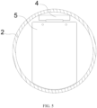
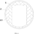
- FIG. 5 and FIG. 6 respectively show a right view and a left view of a horizontal section of the discharge pipe of the chiller according to the embodiment of the invention.
- the rotating shaft 4 is fixed to a top portion of the inner wall of the discharge pipe 2
- an upper edge of the valve plate 5 is connected to the rotating shaft 4
- two side edges of the valve plate 5 are formed as parallel straight outer edges
- a lower edge of the valve plate 5 matches the shape of the inner wall at the bottom portion of the pipe. Therefore, in a process in which the valve plate 5 rotates and swings from the first position to the second position, the bottom portion of the valve plate 5 swings upward and the upper edge and the outer edges on two sides of the valve plate 5 are not in contact with the inner wall of the pipe. Therefore, it is possible to ensure a flow area while not scraping the inner wall of the discharge pipe 2.
- the limiting portion 6 is an integrally formed limiting plate 61.
- the outer edge of the limiting plate 61 matches the circumferential shape of the inner wall of the discharge pipe 2, and can be fixedly mounted (for example, welded) with the inner wall of the discharge pipe 2 over the entire circumferential range. Inner edges of the side portions, the bottom portion and the top portion of the limiting plate 61 enclose to form a flow port.
- the inner edges of the limiting plate 61 on the side portions abuts against the parallel straight outer edges on both the two sides of the valve plate 5, the top limiting plate 61 corresponds to the rotating shaft 4, a lower edge of the top limiting plate 61 abuts against the upper edge of the valve plate 5, and the bottom limiting plate 61 abuts against the lower edge of the valve plate 5, so that the valve plate 5 can completely cover the flow port in the first position to close the discharge pipe 2. Since the outer edges of the valve plate 5 abut against the limiting portion 6, the sealing performance of the closed structure of the valve plate 5 to the discharge pipe 2 is better, and the valve plate 5 is firmer and more reliable.
- FIG. 7 and FIG. 8 respectively show a right view and a left view a horizontal section of a discharge pipe of another chiller according to the embodiment of the invention.
- FIG. 9 shows a schematic cross-sectional view of the horizontal section of the discharge pipe of another chiller according to the embodiment of the invention.
- the rotating shaft 4 is fixed to the top portion of the inner wall of the discharge pipe 2, two side edges of the valve plate 5 are formed as parallel straight outer edges, and the upper edge and the lower edge of the valve plate 5 match the shape of the inner wall of the bottom portion of the pipe, so that the top portion and the bottom portion of the valve plate 5 in the first position (the position of the solid line valve plate 5 in the drawing) both abut against the inner wall of the discharge pipe 2, and the rotating shaft 4 is connected to a middle portion of the valve plate 5 (excluding the upper edge and the lower edge of the valve plate 5).
- valve plate 5 rotates and swings from the first position to the second position (the position of the dotted line valve plate 5 in the drawing)
- the outer edges on two sides of the valve plate 5 are not in contact with the inner wall of the pipe, so that a larger flow area can be obtained and scratches with the inner wall of the discharge pipe 2 can be reduced.
- the limiting portion 6 includes a side plate 62 and a bottom plate 63.
- the side plate 62 is formed by a side portion of the inner wall of the discharge pipe 2 extending radially inward
- the bottom plate 63 is formed by a bottom portion of the inner wall of the discharge pipe 2 extending radially inward
- inner edges of the side plate 62 and the bottom plate 63 and the inner wall of the discharge pipe 2 enclose to form a large flow port.
- the inner edges of the side plate 62 abuts against the parallel straight outer edges on two sides of the valve plate 5, and the bottom plate 63 abuts against the lower edge of the valve plate 5, so that the valve plate 5 can abut against the limiting portion 6 in the first position to close the discharge pipe 2.
- the limiting portion 6 of the chiller may have elasticity, so that when the lower edge of the valve plate 5 abuts against the limiting portion 6, the valve plate 5 can be elastically pressed against the limiting portion 6, thereby improving the sealing performance and having a certain buffering effect on the impact of the refrigerant flowing back.
- both the rotating shaft 4 and the valve plate 5 are disposed close to the outlet of the compressor 1, so that a distance between a one-way valve including the rotating shaft 4 and the valve plate 5 and the outlet of the compressor 1 is reduced as much as possible, thereby minimizing the gas capacity in this section of the pipeline and reducing the possibility of reverse rotation of the compressor caused by backflow.
Landscapes
- Engineering & Computer Science (AREA)
- Physics & Mathematics (AREA)
- Mechanical Engineering (AREA)
- Thermal Sciences (AREA)
- General Engineering & Computer Science (AREA)
- Check Valves (AREA)
- Applications Or Details Of Rotary Compressors (AREA)
- Compressor (AREA)
Abstract
The invention provides a chiller including a compressor (1) and a condenser (3), in which an outlet (11) of the compressor (1) communicates with an inlet (31) of the condenser (3) through a discharge pipe (2), a rotating shaft (4) and a valve plate (5) having a counterweight are further disposed in the discharge pipe (2), the rotating shaft (4) is fixed on an inner wall of the discharge pipe (2), the valve plate (5) can rotate around the rotating shaft (4), and a rotatable stroke of the valve plate (5) includes swinging down to a first position to close the discharge pipe (2), and swinging up to a second position toward a side away from the outlet (11) of the compressor (1) to open the discharge pipe (2).
Description
- The invention relates to the technical field of air conditioners, in particular to a chiller.
- When a chiller of a heating, ventilation, and air conditioning system operates normally, a refrigerant is compressed by a compressor and then discharged into a condenser from an outlet of the compressor through a discharge pipe. When the chiller is shut down unexpectedly, the uncondensed refrigerant may flow back into the compressor through the discharge pipe, which brings a risk to the stability of a bearing component and a rotating shaft of the compressor, thereby affecting the subsequent normal operation of the chiller.
- At present, a common solution is to install a spring-loaded check valve in the discharge pipe. However, a maximum opening of the spring-loaded check valve is usually 45 degrees, which may hinder the normal discharge of the compressor, causing a constant pressure drop (about 1 psi to 2 psi) on two sides of the spring-loaded check valve and affecting the working efficiency of the chiller. Further, since a spring is likely to age and be damaged in the working environment at the outlet of the compressor, the reliability of the spring-loaded check valve is greatly limited by the reliability of the spring, which reduces the overall reliability of the chiller and increases maintenance costs.
- An object of the invention is to provide a chiller to at least solve or alleviate some of the problems existing in the related art.
- According to a first aspect of the invention there is provided a chiller including a compressor and a condenser, in which an outlet of the compressor communicates with an inlet of the condenser through a discharge pipe, a rotating shaft and a valve plate having a counterweight are further disposed in the discharge pipe, the rotating shaft is fixed on an inner wall of the discharge pipe, the valve plate can rotate around the rotating shaft, and a rotatable stroke of the valve plate includes swinging down to a first position to close the discharge pipe, and swinging up to a second position toward a side away from the outlet of the compressor to open the discharge pipe.
- Optionally, the compressor is disposed above the condenser, the discharge pipe has a main body section extending in a vertical direction and a bent section formed by bending the main body section laterally, the bent section communicates with the outlet located on a side surface of the compressor, and the rotating shaft and the valve plate are both disposed in the bent section.
- Optionally, the bent section further includes a horizontal section extending horizontally, and the rotating shaft and the valve plate are disposed in the horizontal section.
- Optionally, the chiller further includes a limiting portion formed by the inner wall of the discharge pipe extending radially inward and disposed on a side of the valve plate closer to the outlet of the compressor, in which an outer edge of the valve plate at the first position abuts against an inner edge of the limiting portion.
- Optionally, the limiting portion is an integrally formed limiting plate having a complete outer edge and connected to the inner wall of the discharge pipe over entire circumferential range.
- Optionally, the limiting portion includes a side plate formed by a side portion of the inner wall of the discharge pipe extending radially inward, and a bottom plate formed by a bottom portion of the inner wall of the discharge pipe extending radially inward, a top portion of the valve plate at the first position abuts against the inner wall of the discharge pipe, a side edge of the valve plate abuts against the side plate, and a lower edge of the valve plate abuts against the bottom plate.
- Optionally, the limiting portion is elastic.
- Optionally, the limiting portion is fixed to the inner wall of the discharge pipe by welding.
- Optionally, the limiting portion is inclined at an angle of 0° to 3° with respect to the vertical direction.
- Optionally, the compressor is a centrifugal compressor.
- Optionally, the valve plate swings down to the first position only by self weight that provides a driving force.
- Optionally, the counterweight has a weight of 1 kg to 15 kg.
- According to the chiller of the invention, the valve plate having the counterweight is rotatably mounted on the rotating shaft. When the chiller operates normally, the valve plate can rotate about the rotating shaft and swing up to the second position to maintain a large opening. The valve plate can also spontaneously adjust the opening in response to a change in a flow rate of a refrigerant, depending on the flow rate of the refrigerant. When the chiller is shut down, the valve plate can swing down to the first position only under the driving of gravity so as to close the discharge pipe and prevent refrigerant backflow. Since there is no need to provide deformation driving components such as springs and the closing of the valve plate is driven only by gravity, the reliability of the check valve is better, and maintenance costs can be effectively reduced.
- Certain exemplary embodiments will now be described in greater detail by way of example only and with reference to the accompanying drawings in which:
-
FIG. 1 shows an overall diagram of a chiller. -
FIG. 2 shows a schematic cross-sectional view of a discharge pipe of the chiller. -
FIG. 3 shows a schematic structural diagram of a valve plate in a bent section rotating to a first position. -
FIG. 4 shows a schematic structural diagram of the valve plate in the bent section rotating to a second position. -
FIG. 5 shows a right view of a horizontal section of the discharge pipe of the chiller. -
FIG. 6 shows a left view of the horizontal section of the discharge pipe of the chiller. -
FIG. 7 shows a right view of a horizontal section of a discharge pipe of another chiller. -
FIG. 8 shows a left view of the horizontal section of the discharge pipe of another chiller. -
FIG. 9 shows a schematic cross-sectional view of the horizontal section of the discharge pipe of another chiller. - List of Reference Numerals: 1-compressor; 11-outlet of compressor; 2-discharge pipe; 21-bent section; 21a-upper bent section; 21b-lower bent section; 22-main body section; 3-condenser; 3 1-inlet of condenser; 4-rotating shaft; 5-valve plate; 6-limiting portion; 61-limiting plate; 62-side plate; 63-bottom plate.
- First, it should be noted that compositions, working principles, characteristics, advantages and the like of a chiller according to the invention will be described below in an illustrative manner. However, it should be understood that all descriptions are given for illustrative purposes only and therefore should not be construed as any limitation to the invention.
- In addition, for any single technical feature described or implied in the embodiments mentioned herein, or any single technical feature shown or implied in the accompanying drawings, the invention still allows any combination or deletion between these technical features (or equivalents thereof) without any technical obstacles, thereby obtaining more other embodiments of the invention that may not be directly mentioned herein.
- The term "swings down" means to swing downward or sideways in the direction of gravity, and "swings up" means to swing upward or sideways in the direction of gravity.
- The valve plate has a "counterweight", which may mean that a valve plate with a heavy weight is used, or additional accessories such as a counterweight block or a counterweight plate may be added and fixed to a main body of the valve plate. The weight of the counterweight may be selected as long as a discharge pipe can be normally opened when a compressor is discharged and the discharge pipe can be stably closed when backflow occurs. In some embodiments, the weight of the counterweight may be 2 kg to 15 kg. When a valve plate within this counterweight range is closed, the force acting on a unit flow area is about 1 psi to 10 psi, which can ensure the reliable closing of the discharge pipe. At the same time, when a refrigerant flows normally in the discharge pipe, the valve plate can also be quickly driven to open.
-
FIG. 1 shows an overall diagram of a chiller according to an embodiment of the invention. As shown inFIG. 1 , the chiller according to the embodiment of the invention includes acompressor 1 and acondenser 3. Anoutlet 11 of the compressor communicates with aninlet 31 of the condenser through adischarge pipe 2. The specific type of thecompressor 1 is not limited here. In some embodiments, thecompressor 1 may be a screw compressor, a centrifugal compressor, a scroll compressor, or the like. - Preferably, the
compressor 1 is a centrifugal compressor. - The specific type of the
condenser 3 is not limited here. In some embodiments, the condenser may be a water-cooled condenser, an air-cooled condenser, or the like, preferably a water-cooled condenser. - Taking a centrifugal compressor as an example, the centrifugal compressor uses centrifugal force to drive a refrigerant to discharge from a low-pressure side to a high-pressure side of a system, and the high-pressure refrigerant is discharged from the
outlet 11 of the compressor to thecondenser 3 through thedischarge pipe 2. When the exhaust pressure is too high, that is, the pressure in thecondenser 3 or thedischarge pipe 2 is too high, the centrifugal compressor may stop pumping as a pressure difference cannot be overcome, and a "surge" phenomenon may occur. In addition, when the chiller is shut down, the high-temperature and high-pressure refrigerant may flow back along thedischarge pipe 2 and impact a bearing component or a rotating shaft of the centrifugal compressor, thereby affecting the subsequent normal operation of the chiller. -
FIG. 2 shows a schematic cross-sectional view of a discharge pipe of the chiller according to the embodiment of the invention. As shown inFIG. 2 , the chiller according to the embodiment of the invention further includes a rotatingshaft 4 disposed in thedischarge pipe 2 and avalve plate 5 having a counterweight. The rotatingshaft 4 is fixed to an inner wall of thedischarge pipe 2, and thevalve plate 5 can rotate around the rotatingshaft 4 under the action of gravity or a combination of gravity and other driving forces. - In the chiller according to the embodiment of the invention, the
valve plate 5 having a counterweight is rotatably mounted on the rotatingshaft 4. - When the chiller operates normally, the
compressor 1 continuously discharges a refrigerant into thedischarge pipe 2, the high-temperature and high-pressure refrigerant continuously flows from theoutlet 11 of the compressor to theinlet 31 of the condenser, and thevalve plate 5 swings up to a side away from theoutlet 11 of the compressor under the driving of the refrigerant. Since no spring is provided and there is no restriction of the spring elastic force, thevalve plate 5 can rotate to a second position under the driving of a pressure difference on two sides and maintain a large opening. Further, depending on a flow rate of the refrigerant, the driving force of the refrigerant on thevalve plate 5 also changes accordingly. Therefore, the opening of thevalve plate 5 can spontaneously respond to a change in the flow rate of the refrigerant, thereby avoiding excessive pressure drop of theoutlet 11 of the compressor caused by obstruction of the flow of the refrigerant in adischarge pipe 2 and avoiding the loss of pressure heads. - When the chiller is normally shut down, that is, there is no refrigerant flowing in the
discharge pipe 2, thevalve plate 5 can swing down to the first position only by its own gravity to close thedischarge pipe 2 and avoid backflow of the high-temperature and high-pressure refrigerant. In a case of unexpected shutdown, if a certain amount of refrigerant flows back, the refrigerant flowing back can further accelerate the downward swing of thevalve plate 5, thereby reducing the backflow as much as possible. - In some embodiments of the invention, the
valve plate 5 and therotating shaft 4 of the chiller can maintain a large opening when the chiller operates normally, and can spontaneously adjust the opening in response to a change in the flow rate of the refrigerant. In addition, since there is no need to provide elastic elements such as springs and the closing of thevalve plate 5 is driven only by gravity, the reliability of the check valve is better, and maintenance costs can be effectively reduced. - The
valve plate 5 may rotate and swing down to a first position where the valve plate extends in the direction of gravity, or may swing down to a first position inclined to the direction of gravity, as long as thevalve plate 5 can stop swinging down and close thedischarge pipe 2 in this position. For example, thevalve plate 5 may be inclined at an angle of 0° to 3° with respect to the direction of gravity. The own gravity of thevalve plate 5 can be used to set a certain inclination angle, increase the stress between thevalve plate 5 and a limitingportion 6, and increase the reliability of thevalve plate 5 closing thedischarge pipe 2 when thevalve plate 5 is in the first position. - In the chiller according to the embodiment of the invention, the
compressor 1 and thecondenser 3 may be disposed according to the actual use environment. For example, thecompressor 1 and thecondenser 3 may be stacked at least partially overlapped in a height direction, theoutlet 11 of the compressor and theinlet 31 of the condenser may be disposed on the same side, and two ends of thedischarge pipe 2 are bent to respectively communicate with theoutlet 11 of the compressor and theinlet 31 of the condenser, so that the internal structure of the chiller is more compact. - In some embodiments, a
bent section 21 further includes a horizontal section extending horizontally, and therotating shaft 4 and thevalve plate 5 are disposed in the horizontal section of thedischarge pipe 2. Thevalve plate 5 can quickly swing down to abut against a bottom portion of the inner wall of thedischarge pipe 2 in thehorizontal discharge pipe 2, or can be opened to a position close to, equal to or even exceeding 90° to increase the maximum opening of thedischarge pipe 2. - In some other embodiments, the
compressor 1 is disposed above thecondenser 3, and thedischarge pipe 2 has amain body section 22 extending in a vertical direction and thebent section 21 formed by bending themain body section 22 laterally. With reference toFIG. 1 , an upper portion and a lower portion of thedischarge pipe 2 are each formed with thebent section 21. An upperbent section 21a communicates with the outlet located on a side surface of thecompressor 1, and a lowerbent section 21b communicates with the inlet located on a side surface of thecondenser 3. Thecompressor 1 and thecondenser 3 are stacked up and down to make the internal structure of the chiller more compact. - Hereinafter, an assembly structure of the
valve plate 5 and therotating shaft 4 in thebent section 21 of thedischarge pipe 2 will be described by taking the case in which thevalve plate 5 and therotating shaft 4 are disposed in the upperbent section 21a as an example.FIG. 3 shows a schematic structural diagram of thevalve plate 5 in thebent section 21 rotating to the first position according to the embodiment of the invention.FIG. 4 shows a schematic structural diagram of thevalve plate 5 in thebent section 21 rotating to the second position according to the embodiment of the invention. - With reference to
FIGS. 3 and4 , in thebent section 21, therotating shaft 4 is fixed to a top portion of an inner wall of thebent section 21, and thevalve plate 5 is disposed below therotating shaft 4 and can rotate around therotating shaft 4. - When the compressor is not operating and no refrigerant flows in the
discharge pipe 2, thevalve plate 5 rotates to swing down to the first position under the driving of its own gravity. Thevalve plate 5 has a height greater than a diameter of thedischarge pipe 2. After thevalve plate 5 swings down, a bottom end of thevalve plate 5 can directly abut against a bent lower surface of the inner wall of thebent section 21, thereby closing thedischarge pipe 2 and blocking the refrigerant flowing back from thecondenser 3 if necessary. When the compressor operates, the refrigerant discharged from thecompressor 1 is discharged to thecondenser 3 through thedischarge pipe 2, and thevalve plate 5 is driven by the pressure difference and the flowing refrigerant to swing up to the second position toward the side away from theoutlet 11 of the compressor, thereby opening thedischarge pipe 2. When the pressure difference is large enough, thevalve plate 5 can be opened until abutting against the top portion of the inner wall of thebent section 21 of thedischarge pipe 2, thereby reducing the obstruction to the flow of the refrigerant in thedischarge pipe 2 and maintaining smooth flow of the refrigerant in thedischarge pipe 2. - The chiller further includes the limiting
portion 6 formed by the inner wall of thedischarge pipe 2 extending radially inward. The limitingportion 6 is disposed on a side of thevalve plate 5 closer to theoutlet 11 of the compressor, and an outer edge of thevalve plate 5 in the first position abuts against an inner edge of the limitingportion 6. The arrangement in which the limitingportion 6 abuts against thevalve plate 5 can ensure the reliability of thevalve plate 5 closing thedischarge pipe 2 in the first position, and prevent thevalve plate 5 from swinging in the opposite direction (that is, swinging to the side closer to the outlet of the compressor) under the impact of the refrigerant flowing back. - The limiting
portion 6 may be directly formed by a protrusion on the inner wall of the discharge pipe 2 (as shown in the structure ofFIGS. 3 and4 ), or may be fixedly mounted on the inner wall of thedischarge pipe 2. Alternatively, in some embodiments, an inner diameter of thedischarge pipe 2 on the side of thevalve plate 5 closer to theoutlet 11 of the compressor may be slightly reduced (as shown inFIG. 2 ) to form the limitingportion 6, so that when the valve plate swings down and is closed, the outer edge of the valve plate can abut against the entire circumference of thedischarge pipe 2 with a small inner diameter, and the above can be applied to the chiller of the specification. - In some embodiments, the
discharge pipe 2 and the limitingportion 6 are both made of metal, and the limitingportion 6 is welded and fixed to the inner wall of thedischarge pipe 2, which can increase the reliability and firmness of the limitingportion 6. - In some embodiments of the invention, the limiting
portion 6 may be an integrally formed limitingplate 61 having a complete outer edge and connected to the inner wall of thedischarge pipe 2 over entire circumferential range. Therefore, when thevalve plate 5 is in the first position, the outer edge of the entire circumference of thevalve plate 5 can abut against the inner edge of the limitingplate 61, so that thedischarge pipe 2 can be closed more tightly, and a small amount of refrigerant is prevented from flowing back through a gap between thevalve plate 5 and the limitingportion 6. - In some other embodiments of the invention, the limiting
portion 6 may not have a complete outer edge, but one or more limitingplates 61 are disposed at intervals in a circumferential range of the inner wall of thedischarge pipe 2. Correspondingly, the outer edge of thevalve plate 5 is in contact with the inner wall of thedischarge pipe 2, and the other portion of thevalve plate 5 abuts against the limitingplate 61. Since the limitingplate 61 is not connected to the inner wall of thedischarge pipe 2 in the entire circumference, the flow of the refrigerant in thedischarge pipe 2 is less affected, a maximum flow rate in thedischarge pipe 2 is larger, and the working efficiency of the chiller is improved. -
FIGS. 5 to 9 show two assembly structures thevalve plates 5 and therotating shaft 4 in the discharge pipe of the chiller according to the invention. Hereinafter, further description will be given with reference to the accompanying drawings and specific examples. -
FIG. 5 andFIG. 6 respectively show a right view and a left view of a horizontal section of the discharge pipe of the chiller according to the embodiment of the invention. With reference toFIGS. 5 and6 , therotating shaft 4 is fixed to a top portion of the inner wall of thedischarge pipe 2, an upper edge of thevalve plate 5 is connected to therotating shaft 4, two side edges of thevalve plate 5 are formed as parallel straight outer edges, and a lower edge of thevalve plate 5 matches the shape of the inner wall at the bottom portion of the pipe. Therefore, in a process in which thevalve plate 5 rotates and swings from the first position to the second position, the bottom portion of thevalve plate 5 swings upward and the upper edge and the outer edges on two sides of thevalve plate 5 are not in contact with the inner wall of the pipe. Therefore, it is possible to ensure a flow area while not scraping the inner wall of thedischarge pipe 2. - Correspondingly, referring to
FIG. 6 , the limitingportion 6 is an integrally formed limitingplate 61. The outer edge of the limitingplate 61 matches the circumferential shape of the inner wall of thedischarge pipe 2, and can be fixedly mounted (for example, welded) with the inner wall of thedischarge pipe 2 over the entire circumferential range. Inner edges of the side portions, the bottom portion and the top portion of the limitingplate 61 enclose to form a flow port. The inner edges of the limitingplate 61 on the side portions abuts against the parallel straight outer edges on both the two sides of thevalve plate 5, thetop limiting plate 61 corresponds to therotating shaft 4, a lower edge of the top limitingplate 61 abuts against the upper edge of thevalve plate 5, and thebottom limiting plate 61 abuts against the lower edge of thevalve plate 5, so that thevalve plate 5 can completely cover the flow port in the first position to close thedischarge pipe 2. Since the outer edges of thevalve plate 5 abut against the limitingportion 6, the sealing performance of the closed structure of thevalve plate 5 to thedischarge pipe 2 is better, and thevalve plate 5 is firmer and more reliable. -
FIG. 7 andFIG. 8 respectively show a right view and a left view a horizontal section of a discharge pipe of another chiller according to the embodiment of the invention.FIG. 9 shows a schematic cross-sectional view of the horizontal section of the discharge pipe of another chiller according to the embodiment of the invention. With reference toFIGS. 7 to 9 , therotating shaft 4 is fixed to the top portion of the inner wall of thedischarge pipe 2, two side edges of thevalve plate 5 are formed as parallel straight outer edges, and the upper edge and the lower edge of thevalve plate 5 match the shape of the inner wall of the bottom portion of the pipe, so that the top portion and the bottom portion of thevalve plate 5 in the first position (the position of the solidline valve plate 5 in the drawing) both abut against the inner wall of thedischarge pipe 2, and therotating shaft 4 is connected to a middle portion of the valve plate 5 (excluding the upper edge and the lower edge of the valve plate 5). In a process in which thevalve plate 5 rotates and swings from the first position to the second position (the position of the dottedline valve plate 5 in the drawing), the outer edges on two sides of thevalve plate 5 are not in contact with the inner wall of the pipe, so that a larger flow area can be obtained and scratches with the inner wall of thedischarge pipe 2 can be reduced. - Correspondingly, the limiting
portion 6 includes aside plate 62 and abottom plate 63. Theside plate 62 is formed by a side portion of the inner wall of thedischarge pipe 2 extending radially inward, thebottom plate 63 is formed by a bottom portion of the inner wall of thedischarge pipe 2 extending radially inward, and inner edges of theside plate 62 and thebottom plate 63 and the inner wall of thedischarge pipe 2 enclose to form a large flow port. The inner edges of theside plate 62 abuts against the parallel straight outer edges on two sides of thevalve plate 5, and thebottom plate 63 abuts against the lower edge of thevalve plate 5, so that thevalve plate 5 can abut against the limitingportion 6 in the first position to close thedischarge pipe 2. When thevalve plate 5 rotates and swings to the second position, since the area of the limitingportion 6 is smaller than that of the embodiments ofFIGS. 5 and6 , the area of the flow port through which the refrigerant flows is larger, which helps to improve the working efficiency of the chiller. - The limiting
portion 6 of the chiller according to some embodiments of the invention may have elasticity, so that when the lower edge of thevalve plate 5 abuts against the limitingportion 6, thevalve plate 5 can be elastically pressed against the limitingportion 6, thereby improving the sealing performance and having a certain buffering effect on the impact of the refrigerant flowing back. - In some embodiments of the invention, both the
rotating shaft 4 and thevalve plate 5 are disposed close to the outlet of thecompressor 1, so that a distance between a one-way valve including therotating shaft 4 and thevalve plate 5 and the outlet of thecompressor 1 is reduced as much as possible, thereby minimizing the gas capacity in this section of the pipeline and reducing the possibility of reverse rotation of the compressor caused by backflow. - The above embodiments are merely preferred embodiments of the invention and are not intended to limit the invention.
Claims (12)
- A chiller comprising:a compressor (1);a condenser (3);a discharge pipe (2) configured to allow an outlet (11) of the compressor to communicate with an inlet (31) of the condenser;a rotating shaft (4) fixed to an inner wall of the discharge pipe; anda valve plate (5) having a counterweight and configured to rotate about the rotating shaft, a rotatable stroke of the valve plate including swinging down to a first position to close the discharge pipe, and swinging up to a second position toward a side away from the outlet of the compressor to open the discharge pipe.
- The chiller according to claim 1, wherein the compressor (1) is disposed above the condenser (3), the discharge pipe (2) has a main body section (22) extending in a vertical direction and a bent section (21) formed by bending the main body section laterally, the bent section communicates with the outlet (11) located on a side surface of the compressor, and the rotating shaft (4) and the valve plate (5) are both disposed in the bent section.
- The chiller according to claim 2, wherein the bent section (21) further includes a horizontal section extending horizontally, and the rotating shaft (4) and the valve plate (5) are disposed in the horizontal section.
- The chiller according to any preceding claim, further comprising: a limiting portion (6) formed by the inner wall of the discharge pipe extending radially inward and disposed on a side of the valve plate (5) closer to the outlet (11) of the compressor (1), wherein an outer edge of the valve plate at the first position abuts against an inner edge of the limiting portion.
- The chiller according to claim 4, wherein the limiting portion (6) is an integrally formed limiting plate (61) having a complete outer edge and connected to the inner wall of the discharge pipe (2) over entire circumferential range.
- The chiller according to claim 4, wherein the limiting portion (6) includes a side plate (62) formed by a side portion of the inner wall of the discharge pipe (2) extending radially inward, and a bottom plate (63) formed by a bottom portion of the inner wall of the discharge pipe extending radially inward, a top portion of the valve plate (5) at the first position abuts against the inner wall of the discharge pipe, a side edge of the valve plate abuts against the side plate, and a lower edge of the valve plate abuts against the bottom plate.
- The chiller according to any of claims 4 to 6, wherein the limiting portion (6) is elastic.
- The chiller according to any of claims 4 to 7, wherein the limiting portion (6) is fixed to the inner wall of the discharge pipe (2) by welding.
- The chiller according to any of claims 4 to 8, wherein the limiting portion (6) is inclined at an angle of 0° to 3° with respect to the vertical direction.
- The chiller according to any preceding claim, wherein the compressor (1) is a centrifugal compressor.
- The chiller according to any preceding claim, wherein the valve plate (5) swings down to the first position only by self weight that provides a driving force.
- The chiller according to any preceding claim, wherein the counterweight has a weight of 1 kg to 15 kg.
Applications Claiming Priority (1)
| Application Number | Priority Date | Filing Date | Title |
|---|---|---|---|
| CN202311384677.5A CN119879451A (en) | 2023-10-24 | 2023-10-24 | Chiller |
Publications (1)
| Publication Number | Publication Date |
|---|---|
| EP4545879A1 true EP4545879A1 (en) | 2025-04-30 |
Family
ID=93258792
Family Applications (1)
| Application Number | Title | Priority Date | Filing Date |
|---|---|---|---|
| EP24208355.8A Pending EP4545879A1 (en) | 2023-10-24 | 2024-10-23 | Chiller |
Country Status (3)
| Country | Link |
|---|---|
| US (1) | US20250129973A1 (en) |
| EP (1) | EP4545879A1 (en) |
| CN (1) | CN119879451A (en) |
Citations (3)
| Publication number | Priority date | Publication date | Assignee | Title |
|---|---|---|---|---|
| KR20000020855U (en) * | 1999-05-14 | 2000-12-15 | 황한규 | Device for preventing turbo freezer from reverse flow |
| CN216843275U (en) * | 2022-01-27 | 2022-06-28 | 特灵空调系统(中国)有限公司 | Check Valves, Compressors and Chillers |
| US20230288107A1 (en) * | 2022-03-10 | 2023-09-14 | Carrier Corporation | Orifice set and chiller system having it |
-
2023
- 2023-10-24 CN CN202311384677.5A patent/CN119879451A/en active Pending
-
2024
- 2024-10-11 US US18/912,831 patent/US20250129973A1/en active Pending
- 2024-10-23 EP EP24208355.8A patent/EP4545879A1/en active Pending
Patent Citations (3)
| Publication number | Priority date | Publication date | Assignee | Title |
|---|---|---|---|---|
| KR20000020855U (en) * | 1999-05-14 | 2000-12-15 | 황한규 | Device for preventing turbo freezer from reverse flow |
| CN216843275U (en) * | 2022-01-27 | 2022-06-28 | 特灵空调系统(中国)有限公司 | Check Valves, Compressors and Chillers |
| US20230288107A1 (en) * | 2022-03-10 | 2023-09-14 | Carrier Corporation | Orifice set and chiller system having it |
Also Published As
| Publication number | Publication date |
|---|---|
| CN119879451A (en) | 2025-04-25 |
| US20250129973A1 (en) | 2025-04-24 |
Similar Documents
| Publication | Publication Date | Title |
|---|---|---|
| KR102400430B1 (en) | Scroll compressor | |
| CN101424267B (en) | Rotary compressor | |
| WO2022077754A1 (en) | Compressor and refrigeration system | |
| WO2026040702A1 (en) | Vapor injection compressor and air conditioner | |
| US20250129973A1 (en) | Chiller | |
| WO2020125064A1 (en) | Scroll compressor, air conditioner, and backpressure adjustment method for scroll compressor | |
| CN111878395B (en) | Scroll compressor having a rotor with a rotor shaft having a rotor shaft with a | |
| CN103267017B (en) | There is the screw compressor of novel exhaust mouth structure and exhaust valve component | |
| US20210310472A1 (en) | Compressor and electronic device using the same | |
| KR19990065075A (en) | Reverse rotation prevention structure of scroll compressor | |
| CN220059910U (en) | Check valve assembly and compressor with same | |
| CN108759212B (en) | Shutdown control method, system and chiller of chiller | |
| CN217712964U (en) | Exhaust assembly, compressor and temperature adjusting device | |
| CN112901497B (en) | Exhaust valve sheet assembly, compressor and air conditioner with same | |
| CN218882524U (en) | Silencer for compressor, compressor and air conditioner | |
| CN115523147A (en) | Flange assembly of compressor, compressor and air conditioner | |
| CN203906298U (en) | Horizontal type frequency inverter compressor | |
| CN111720322B (en) | Compressor | |
| CN111720316B (en) | Rotary compressor | |
| CN208966584U (en) | The pump housing, horizontal compressor | |
| JP7853624B2 (en) | Rotary compressor and refrigeration cycle system | |
| CN206246356U (en) | Screw compressor and refrigeration plant | |
| CN207420875U (en) | Gas deflation assembly, pump assembly, compressor and heat transmission equipment | |
| CN219754804U (en) | A kind of compressor | |
| CN119934025B (en) | Cylinder structure and horizontal rotor compressor |
Legal Events
| Date | Code | Title | Description |
|---|---|---|---|
| PUAI | Public reference made under article 153(3) epc to a published international application that has entered the european phase |
Free format text: ORIGINAL CODE: 0009012 |
|
| STAA | Information on the status of an ep patent application or granted ep patent |
Free format text: STATUS: THE APPLICATION HAS BEEN PUBLISHED |
|
| AK | Designated contracting states |
Kind code of ref document: A1 Designated state(s): AL AT BE BG CH CY CZ DE DK EE ES FI FR GB GR HR HU IE IS IT LI LT LU LV MC ME MK MT NL NO PL PT RO RS SE SI SK SM TR |
|
| STAA | Information on the status of an ep patent application or granted ep patent |
Free format text: STATUS: REQUEST FOR EXAMINATION WAS MADE |
|
| 17P | Request for examination filed |
Effective date: 20250626 |