EP4545865A1 - Method for configuring a hybrid system - Google Patents
Method for configuring a hybrid system Download PDFInfo
- Publication number
- EP4545865A1 EP4545865A1 EP23206379.2A EP23206379A EP4545865A1 EP 4545865 A1 EP4545865 A1 EP 4545865A1 EP 23206379 A EP23206379 A EP 23206379A EP 4545865 A1 EP4545865 A1 EP 4545865A1
- Authority
- EP
- European Patent Office
- Prior art keywords
- type
- heat generator
- control unit
- configuration
- hybrid system
- Prior art date
- Legal status (The legal status is an assumption and is not a legal conclusion. Google has not performed a legal analysis and makes no representation as to the accuracy of the status listed.)
- Withdrawn
Links
Images



Classifications
-
- F—MECHANICAL ENGINEERING; LIGHTING; HEATING; WEAPONS; BLASTING
- F24—HEATING; RANGES; VENTILATING
- F24D—DOMESTIC- OR SPACE-HEATING SYSTEMS, e.g. CENTRAL HEATING SYSTEMS; DOMESTIC HOT-WATER SUPPLY SYSTEMS; ELEMENTS OR COMPONENTS THEREFOR
- F24D19/00—Details
- F24D19/10—Arrangement or mounting of control or safety devices
- F24D19/1006—Arrangement or mounting of control or safety devices for water heating systems
- F24D19/1009—Arrangement or mounting of control or safety devices for water heating systems for central heating
- F24D19/1039—Arrangement or mounting of control or safety devices for water heating systems for central heating the system uses a heat pump
-
- F—MECHANICAL ENGINEERING; LIGHTING; HEATING; WEAPONS; BLASTING
- F24—HEATING; RANGES; VENTILATING
- F24D—DOMESTIC- OR SPACE-HEATING SYSTEMS, e.g. CENTRAL HEATING SYSTEMS; DOMESTIC HOT-WATER SUPPLY SYSTEMS; ELEMENTS OR COMPONENTS THEREFOR
- F24D19/00—Details
- F24D19/10—Arrangement or mounting of control or safety devices
- F24D19/1006—Arrangement or mounting of control or safety devices for water heating systems
- F24D19/1066—Arrangement or mounting of control or safety devices for water heating systems for the combination of central heating and domestic hot water
- F24D19/1072—Arrangement or mounting of control or safety devices for water heating systems for the combination of central heating and domestic hot water the system uses a heat pump
-
- F—MECHANICAL ENGINEERING; LIGHTING; HEATING; WEAPONS; BLASTING
- F24—HEATING; RANGES; VENTILATING
- F24D—DOMESTIC- OR SPACE-HEATING SYSTEMS, e.g. CENTRAL HEATING SYSTEMS; DOMESTIC HOT-WATER SUPPLY SYSTEMS; ELEMENTS OR COMPONENTS THEREFOR
- F24D3/00—Hot-water central heating systems
- F24D3/10—Feed-line arrangements, e.g. providing for heat-accumulator tanks, expansion tanks ; Hydraulic components of a central heating system
- F24D3/1058—Feed-line arrangements, e.g. providing for heat-accumulator tanks, expansion tanks ; Hydraulic components of a central heating system disposition of pipes and pipe connections
- F24D3/1066—Distributors for heating liquids
-
- F—MECHANICAL ENGINEERING; LIGHTING; HEATING; WEAPONS; BLASTING
- F24—HEATING; RANGES; VENTILATING
- F24H—FLUID HEATERS, e.g. WATER OR AIR HEATERS, HAVING HEAT-GENERATING MEANS, e.g. HEAT PUMPS, IN GENERAL
- F24H15/00—Control of fluid heaters
- F24H15/40—Control of fluid heaters characterised by the type of controllers
- F24H15/414—Control of fluid heaters characterised by the type of controllers using electronic processing, e.g. computer-based
- F24H15/443—Control of fluid heaters characterised by the type of controllers using electronic processing, e.g. computer-based using a central controller connected to several sub-controllers
-
- F—MECHANICAL ENGINEERING; LIGHTING; HEATING; WEAPONS; BLASTING
- F24—HEATING; RANGES; VENTILATING
- F24D—DOMESTIC- OR SPACE-HEATING SYSTEMS, e.g. CENTRAL HEATING SYSTEMS; DOMESTIC HOT-WATER SUPPLY SYSTEMS; ELEMENTS OR COMPONENTS THEREFOR
- F24D2200/00—Heat sources or energy sources
- F24D2200/04—Gas or oil fired boiler
-
- F—MECHANICAL ENGINEERING; LIGHTING; HEATING; WEAPONS; BLASTING
- F24—HEATING; RANGES; VENTILATING
- F24D—DOMESTIC- OR SPACE-HEATING SYSTEMS, e.g. CENTRAL HEATING SYSTEMS; DOMESTIC HOT-WATER SUPPLY SYSTEMS; ELEMENTS OR COMPONENTS THEREFOR
- F24D2200/00—Heat sources or energy sources
- F24D2200/12—Heat pump
-
- F—MECHANICAL ENGINEERING; LIGHTING; HEATING; WEAPONS; BLASTING
- F24—HEATING; RANGES; VENTILATING
- F24D—DOMESTIC- OR SPACE-HEATING SYSTEMS, e.g. CENTRAL HEATING SYSTEMS; DOMESTIC HOT-WATER SUPPLY SYSTEMS; ELEMENTS OR COMPONENTS THEREFOR
- F24D2200/00—Heat sources or energy sources
- F24D2200/32—Heat sources or energy sources involving multiple heat sources in combination or as alternative heat sources
-
- F—MECHANICAL ENGINEERING; LIGHTING; HEATING; WEAPONS; BLASTING
- F24—HEATING; RANGES; VENTILATING
- F24H—FLUID HEATERS, e.g. WATER OR AIR HEATERS, HAVING HEAT-GENERATING MEANS, e.g. HEAT PUMPS, IN GENERAL
- F24H15/00—Control of fluid heaters
- F24H15/40—Control of fluid heaters characterised by the type of controllers
- F24H15/493—Control of fluid heaters characterised by the type of controllers specially adapted for enabling recognition of parts newly installed in the fluid heating system, e.g. for retrofitting or for repairing by replacing parts
Definitions
- the invention relates to method for configuring a hybrid system. Additionally, the invention relates to a configuration control device for carrying out said method and a hybrid system comprising such a configuration control device. The invention also relates to a computer program product, a non-transitory computer readable medium and data carrier signal.
- Heat pumps are becoming more and more popular for heating or cooling of houses and as part of the energy transition as being compatible with current climate targets. Heat pumps are seen as one of the central technologies in the global transition to secure and sustainable heating. As part of the energy transition requirements and regulations, a large number of replacement and upgrading of existing installations is expected, which leads to a need that also installers who are trained in boiler installations, only, need to be able to upgrade or replace an existing boiler installation without the need for refrigeration system mechatronic training and certification. Heat pumps can also be used in addition to or in combination with a combustion appliance like a boiler. Using a heat pump in combination with a combustion appliance is referred to as a 'hybrid system'.
- hybrid system describes fitting a heat pump alongside a natural gas, LPG or oil boiler.
- hybrid systems comprise a heat pump and a combustion appliance unit that comprises a combustion appliance device for heating a liquid like water.
- Hybrid heating systems for example are a good option if the installation of a heat pump is possible in principle, but the building still has a higher heating demand until an energy-efficient renovation is carried out, wherein the heating demand is difficult to cover with the heat pump, especially at peak times.
- the object of the invention is therefore to provide a method by means of which at least a partial hybrid system can be installed and is operational for heating independent of the availability or operability of heat pumps and/or heat pump installers trained on refrigeration system mechatronics including the required certifications at the time of commissioning and preparing the heating system to be compatible with climate target regulation.
- a method for configuring a hybrid system which comprises a first type of heat generator, in particular heat pump, a master control unit configured to control the first type of heat generator, a second type of heat generator, in particular a combustion appliance, and a slave control unit configured to control the second type of heat generator, wherein the method comprises the steps that a configuration control unit receives information about the configuration status of the first type of heat generator and of the second type of heat generator and defines the configuration order.
- hybrid systems can be easily configured when a configuration control unit is used which asks for the configuration status of the components of the hybrid system, in particular of the configuration status of the master control unit and/or the fist type of heating generator and/or the second type of heating generator. By asking about the configuration status, it is easily known which components, in particular which control unit and/or which heat generator, are in the hybrid system. Additionally, the configuration status provides information whether a configuration of the control unit and/or the heat generator assigned to the respective control unit is necessary.
- the second type of heat generator can be configured independent of whether the hybrid system comprises the first type of heat generator or not.
- a partial hybrid system is a system which comprises one type of heat generator and means to control both the one type of heat generator, such as a combustion appliance and a further type of heat generator.
- the system preferably further comprises means to fluidically connect a further type of heat generator, such as a heat pump, in particular an outdoor unit of a heat pump with the comprised heat generator, in particular the combustion appliance.
- the installer does not need to be certified to install heat pumps to install the at least partial hybrid system when the hybrid system does not comprise the heat pump.
- the inventive hybrid system has the advantage that it can be installed initially with only one type of heat generator, namely the second type of heat generator.
- Said at least partial hybrid system can be installed by an installer that is specialized on said second type of heat exchanger.
- the heat pump can be installed at a later time if not available at the time of initial installation of the (partial) hybrid system and/or when the installer has time to install it.
- the user can flexibly decide if and when the other type of heat generator, namely the first type of heat generator, shall be installed and yet can prepare his heating system to be compliant with applicable climate regulations.
- the fist type of heat generator differs from the second type of heat generator.
- the first type of heat generator can be a heat pump and the second type of heat generator can be a combustion appliance.
- heat generator it is meant an appliance which is configured such that generated heat is transferred to a liquid that flows in a circuit of the heat generator.
- the master control unit is used to control the operation of the hybrid system, i.e. the operation of the first heat generator and/or the second heat generator during the operation of the hybrid system. Said operation commences after a configuration process in which the configuration control unit is used to configure the hybrid system.
- the operation of the hybrid system can be interrupted and switched to the configuration mode if needed. This can happen when a first type of heat generator is connected to the components of the hybrid system. In said case the master control unit and the first type of heat generator have to be configured.
- the configuration of the master control unit is necessary as the master control unit controls the hybrid system and thus has to know which heat generators are present.
- control unit assigned to the first type of heat generator as master control unit also enables to retrofit existing second type of heat generators to be part of a hybrid system.
- master control unit ensures that the control unit of the second type heat generator to be retrofitted is the slave control unit.
- defining the configuration order it is meant the configuration order according to which the control unit, in particular the master control unit, and heat generator are configured.
- a "combustion appliance device” is any device that is capable to combust fuel.
- the fuel can be oil, natural gas, propane, hydrogen or a mixture of hydrogen and another fuel, such as natural gas or propane. However, it is also possible that the fuel is in solid state. In said case the fuel can be coal, pellets or the same.
- the device can be a boiler and/or comprise a burner, a burner chamber and the heat exchanger. Additionally, the device, in particular boiler, can comprise valves, at least one control unit and a control panel.
- the heat pump unit can be a ground source heat pump or an air source heat pump. Additionally or alternatively, the heat pump can be a split unit or a monobloc unit.
- the heat pump can be configured to heat or cool the fluid medium.
- the heat pump comprises a heat pump heat exchanger in which the heat exchange between the fluid medium and the refrigerant of the heat pump occurs.
- the hybrid system can comprise merely one first type heat generator and merely one second type of heat generator. Thus, the hybrid system does not comprise several heat generators of the first type and/or of the second type. Such a hybrid system has a simple structure.
- the master control unit and/or the slave control unit can comprise one or more processors or be a processor.
- the master control unit can and/or slave control unit can be a control board circuit or can be part of a control board circuit.
- Any or all sensors, pumps, actuators, room units of the first type of heat generator can be connected to the master control unit, wirelessly or via electric lines.
- any or all sensors, pumps, actuators, room units of the first type of heat generator can be connected to the slave control unit, wirelessly or via electric lines.
- the configuration status can be received after the configuration control unit is connected to the master control unit and/or to the slave control unit.
- the configuration control unit can be wirelessly connected to the master control unit/or to the slave control unit.
- the configuration control unit can be connected to the master control unit and/or the slave control unit via an electrical line, in particular a data bus connection.
- the configuration status can be queried from the configuration control unit. This can happen after a configuration mode is started in the configuration control unit, wherein the configuration mode can be started by activating a configuration application that is executed on the configuration control unit.
- the configuration control unit can be configured before the master control unit and/or the at least one heat generator, and/or the slave control is configured. This simplifies the configuration process as configuration control unit can be configured according to the installers needs. For example, the language, used during the configuration process and for operation thereafter, and/or date, time or country can be selected by the installer during the configuration of the configuration control unit.
- first type of heat generator it is determined - as a further step - whether the first type of heat generator is already configured. Additionally or alternatively it is determined whether the first type of heat generator is defined as not present.
- the absence of the first type of heat generator can be indicated in the configuration by setting a parameter defined to for example indicate no flow volume from the first type heat generator to the hybrid system. Alternatively the absence of the first type of heat generator can be automatically detected. This can be realized by detecting whether first type of heat generator sends a presence signal. If said presence signal is not detected, it is determined that the first type of heat generator is not present.
- the configuration control unit can obtain from the configuration status information whether a control unit, in particular the master control unit, and/or a heat generator is present and whether said control unit and/or heat generator are already configured. By checking the configuration status, it can be avoided to configure the control unit twice.
- the master control unit can be configured first and/or can be configured before the at least one heat generator and/or the slave control unit. As the master control unit controls the operation of the hybrid system during the operation of the hybrid system, by configuring the master control unit at first, it is ensured that no unexpected situation can arise.
- the configuration control unit can receive configuration data for configuring the configuration control unit during the configuration process.
- the installer can provide the configuration data by entering it into the configuration control unit.
- the configuration data can be information about the language to be used during the configuration mode, the time, the date and the country. After said data is received, the configuration of the configurating control unit is finalized.
- the hybrid system in particular the configuration control unit, can be restarted.
- configuration data for configuring the master control unit can be received during the configuration process.
- the configuration data can comprise at least one parameter of the heat generator.
- the at least one parameter can comprise information about the power of the heat generator and/or manufacturer of the heat exchanger. It is possible that further parameters are provided and thus received.
- Suitable parameters comprise information such as whether a heat exchanger, in particular of the second heat generator, is an aluminum heat exchanger or stainless steel, whether the second heat generator has a gas adaptive control or not.
- the suitable parameter can further comprise factory settings of parameters, such as how many zones are activated, standard setting for room setpoint for heating curve or the like.
- the master control unit is configured on the basis of the received configuration data. Afterwards, the hybrid system, in particular the master control unit, is restarted. That means, it is restarted before the heat generator is configured.
- the received configuration data received during the configuration process can be provided by the installer. Specifically, the installer can enter said data into an application that is executed in the configuration control unit.
- the configuration control unit and/or the master control unit can determine based on the received configuration status whether the hybrid system comprises a first type heat generator.
- the configuration control unit and/or master control unit can determine that there is no first type of heat generator present if a parameter is received which indicates the absence of the first type of heat generator. Said information can be transmitted to the master control unit.
- the master control unit knows at the end of the configuration process whether the hybrid system comprises a first type of heat generator or not.
- a hybrid system can comprise a second type of heat generator and does not comprise a first type of heat generator.
- the configuration of the second type of heat generator can comprise that a pump for circulating liquid through at least one load circuit is activated.
- the master control unit can activate said pump.
- the pump can be activated for performing a de-aeration.
- Said process can be started automatically when the second type of heat generator shall be configured.
- the configuration process can comprise a functional test of components of the second type of heat generator. With “functional test” it is meant to test whether the component of the second type of heat generator works.
- the components can be at least one valve and at least one tap.
- the configuration process can comprise to enter a gas type that is used for combustion. Also, a gas calibration test can be performed in the configuration process.
- the configuration can also comprise to the process of de-aeration of the circuit of the second type of heat generator. Said process can be controlled by the slave control unit.
- the configuration process comprises further process steps like to check whether the hybrid system comprises an auto filling function. Also it is possible to manually perform load tests and/or configure settings of consumers, in particular defining a heating cur, time programs, etc. Additionally, a hydronic balancing activation can be performed in the configuration process.
- the aforementioned hybrid system according to the first variant i comprises a second type of heat generator that was not configured before and no first type of heat generator.
- the absence of the first type of heat generator can be indicated in the configuration by setting a parameter defined to for example indicate no flow volume from the first type heat generator to the hybrid system.
- This first variant is therefore a partial hybrid system within the meaning of this application.
- the first type of heat generator has also to be configured during the configuration process.
- This configuration comprises activating a further pump of the circuit of the first type of heat generator. That means, said further pump pumps liquid within the circuit of the first type of heat generator. All other configuration steps correspond to the steps mentioned before for the first variant.
- a hybrid according to a third variant differs from the first variant in that it comprises a second type of heat generator that is already configured. That means, the second type of heat generator is retrofitted to become a heat generator of a hybrid system.
- the configuration process differs from the configuration process for the hybrid system according to the first variant in that the configuration process for the second type heat generator does not require a functional test of the second heat generator. In other words, it is not necessary to configure the gas type, check the valve and tap of the secondary heat generator, de-airation of the second heat generator, flue system, gas pressure, consumer valves and taps check and/ or gas calibration.
- the configuration process comprises that the configuration process for the second type of heat generator comprises the activation of the pump for circulating liquid through at least one load circuit by the master control unit.
- the fourth variant differs from the third variant in that it comprises a first type of heat generator. Likewise to the hybrid system according to the third variant, the functional test for the second heat generator type is not required. The configuration of the first type of heat generator is identical to the configuration discussed for the hybrid system according to the second variant.
- the master control unit and the slave control unit can be connected to each other via a data bus. This enables a data communication between the master control unit and the slave control unit.
- the connection between the master control unit and the slave control unit can be releasable. Both control units are active during the configuration process independent of whether the hybrid comprises the first type of heat generator and the second type of heat generator or only the second type of heat generator.
- the master control unit and the slave control unit can be arranged in different units of the hybrid system.
- the master control unit can be arranged in an inner space of a support device of the hybrid system.
- the master control unit and/or the slave control unit and/or the configuration control unit can be arranged on one unit of the hybrid system, in particular the master control unit and the configuration control unit can be arranged on one unit.
- the support device is used to support the combustion appliance.
- the slave control unit can be arranged in an inner space of the combustion appliance.
- the configuration control unit can correspond to a human machine interface of the hybrid system.
- the human machine interface can be part of the first type of heat generator.
- the human machine interface can be part of the second type of the heat generator.
- the first type of heat generator and the second type of heat generator comprise a human machine interface, respectively.
- the installer can use the human machine interface to input at least a part of the commissioning data. At least some of the configuration data mentioned above can be stored in an electric memory of the hybrid system.
- the configuration control unit corresponds to an electric device, in particular a mobile electric device.
- a mobile electric device is a device that an installer can carry to the place where the hybrid system shall be configured and by means of which instructions can be transmitted to the hybrid system.
- an application in particular the computer program product mentioned below, can be executed on the electric device in which the installer can input at least a part of configuring data. Additionally, some remaining configuration data can be stored in the electric device.
- the configuration data can be transferred to the hybrid system, in particular to the master control unit.
- the electric device can be a mobile phone a tablet, a laptop or a computer.
- An electric device can also be configured to allow for remote configuring of the hybrid system.
- the commissioning data is inputted to the hybrid system, in particular to the master control unit, by means of a data processing device.
- the data processing device can be connected to the master control unit so that a data exchange between the data processing device and the master control unit is possible.
- the connection can be via cable or wireless.
- the data processing unit can be an electric device, in particular a computer or a tablet or a mobile phone, by means of which instructions can be transmitted to the hybrid system.
- an application can be executed on the data processing device in which the installer can input commissioning data. Said data can be transferred to the hybrid system, in particular to the master control unit.
- the master control unit can process a heat request independent of whether the hybrid system comprises the first type of heat generator or not. If the hybrid system does not comprise the first type of heat generator, the master control unit ensures that all requested heat is provided by the second type of heat generator.
- climate regulation now requires that e.g. in principle, 65 percent of the heat demand must be covered by renewable energies.
- the currently available renewable energy regulation allows for a simplification.
- the output of the renewable energy heating system is usually less than 65 percent of the heating load. Proof of fulfilling this requirement can be provided by an energy consultant in accordance with the requirements of DIN V 18599.
- a heat pump output of 30 percent of the heating load is sufficient (in accordance with to the partial load point "A" according to DIN EN 14825). The 30 percent refers to the output or the share of the heating load, which can be specified in kilowatts.
- the hybrid system can comprise a first type of heat generator, a master control unit configured to control the first type of heat generator, a second type of heat generator and a slave control unit configured to control the second type of heat generator, wherein the master control unit comprises means for carrying an inventive method.
- the hybrid system is configured to have an operation mode, where the first type of heat generator and/or the second type of heat generator is selected dependent on an outside air temperature and/or an outlet temperature of a load circuit liquid and/or a threshold value of at least 2,5 COP for the first type of heat generator.
- the operation mode can optionally comprise that the first type of heat generator or second type of heat generator, in particular selectively, selected
- the operation mode can further comprise that the first type of heat generator and/or the second type of heat generator is selected such that a heat load of the first type of heat generator is at least 30% of the heat load of the hybrid system at 2 °C outside air temperature and 35 °C outlet temperature of the load circuit liquid.
- the hybrid system can comprise a support unit.
- the support unit can comprise an inner space in which the master control unit is arranged. Additionally or alternatively, the support unit can comprise a distributor by means of which the first type of heat generator and the second type heat generator are fluidically connected to each other.
- the fluid distributor is used to collect and distribute the fluid that flows between the different components of the hybrid system.
- the fluid distributor is a hydronic or hydraulic distributor by means of which the fluid, in particular water, as an energy carrier, is distributed between the heat pump unit, the combustion appliance device and at least one load, in particular several loads.
- the terms hydraulic and hydronic are used as synonymously.
- the distributor is fluidly connected with the first type of heat generator and the second type of heat generator to receive fluid medium from the first type of heat generator and the second type of heat generator that is to be distributed to the one or more load circuits of the hybrid system.
- the load circuit can be a central heating circuit. Additionally or alternatively the load circuit can be domestic hot water circle.
- the fluid distributor has a cavity for receiving the fluid and several inlets and outlets that are fluidically connected to the components of the hybrid.
- a “fluidic connection” between two or more components means that the components are connected in such manner that a fluid, in particular a liquid, can flow from one component to the other component.
- a “fluid path” is the path that the fluid medium flows within the heating or cooling system. As is discussed below more in detail the heating or cooling system comprises several circuits. Said circuits define the fluid path of the fluid medium.
- the support unit can comprise a housing that supports the second type of heat generator.
- Said housing can be attached to a wall, in particular to a wall in a building.
- the housing can be formed by one or more side panels.
- the side panels can comprise at least one of steel, aluminium, a polymeric, in particular a thermoplastic material, and a composite material or can be made of steel, aluminium, a polymeric, in particular a thermoplastic material, and a composite material. Steel provides the side panels with strength.
- the aluminium, the polymeric, in particular the thermoplastic material, and the composite material may be used to reduce the noise generated by the hybrid system and reduce the weight of the respective unit.
- a computer program product comprises instructions which, when the program is executed by a computer, in particular a control unit, cause the computer, in particular the control unit, to carry out an inventive method.
- a non-transitory computer readable medium is provided wherein the non-transitory computer readable medium has stored thereon the inventive computer program product.
- a data carrier signal carrying the inventive computer program product is provided.
- a hybrid system 1 as shown in figure 1 comprises a first type of heat generator 3, a master control unit 2 configured to control the first type of heat generator 3, a second type of heat generator 4 and a slave control unit 5 configured to control the second type of heat generator 4.
- the master control unit 2 and the slave control unit 5 are electrically connected to each other such that a data exchange between the two control units is possible.
- the first type of heat generator 3 is a heat pump and the second type of heat generator 4 is a combustion appliance, in particular a gas boiler.
- the master control unit 2 receives commissioning data relating to the hybrid system 1 and transmits said received commissioning data to the slave control unit 5 for commissioning the second type of heat generator 4 independent of whether the hybrid system 1 comprises the first type of heat generator 3 or not.
- the hybrid system 1 also comprises a support device 7 that is shown in figures 3 to 5 more in detail.
- Said support device 7 is used to support the second type of heat generator 4 and can be attached to a wall.
- a distributor 6 of the hybrid system 1 is arranged in an inner space of the support device 7.
- the distributor 6 has a plurality of inlet and outlet connections by means of which a non-shown cavity of the distributor 6 is fluidically connected to the other components of the hybrid system 1.
- the distributor 6 is fluidically connected to the first type of heat generator 3 and to the second type of heat generator 4. Additionally, the distributor 6 is fluidically connected to a first load circuit 12 and to a second load circuit 13.
- the first load circuit 12 can be a domestic hot water circuit and the second load circuit 13 can be a central heating circuit.
- the distributor 6 is used to fluidically connect the first type of heat generator 3, the second type of heat generator 4, the first load circuit 12 and the second load circuit 13 to each other.
- the hybrid system 1 comprises a pump 11.
- the pump 11 is used to pump liquid within the first and/or second load circuit 12, 13. Referring to the liquid flow direction, the pump 11 is arranged downstream the distributor 6. The pump 11 is also arranged within the inner space of the support device 7.
- the hybrid system 1 comprises a valve 14.
- the valve 14 is arranged within the inner space of the support device 7 and arranged downstream the pump 11.
- the flow rate flowing within the first load circuit 12 or within the second load circuit 13 depends on a valve position.
- the master control unit 2 is connected with the valve 14 and controls the valve position.
- the second type of heat generator 4 which in this embodiment is a combustion appliance, in particular a gas boiler, is only schematically shown. In particular, a burner, valves and the heat exchanger of the combustion appliance are not shown. A part of the combustion appliance circuit 16 that is fluidically connected to distributor 6 is shown. Additionally, another pump is not shown wherein the other pump is used for circulating the liquid within the combustion appliance circuit 16.
- the hybrid system 1 comprises a configurating control unit 20 that can be connected to the master control unit 2 and/or the slave control 5.
- the connection can be a data connection and can be wireless.
- a computer program product is executed on the configurating control unit 20 by means of which the components of the hybrid system 1 can be configured as it is explained in figure 2 .
- Figure 2 shows a flow chart regarding to commissioning of the hybrid system 1 shown in figure 1 .
- the configuration of the control unit 20 implements a data connection to the master control unit 2 and/or the slave control unit 5. Additionally, it is possible in the first step to configure the configuration control unit 5.
- the installer can enter the language to be used during the configuration process, the time, the date and the country in which the hybrid system is located.
- a configuration status is received and a configuration order is determined.
- the master control unit 2 is firstly configured and/or that the master control unit 2 is configured before the second control unit 5 and the heat generators 3, 4 are configured.
- the master control unit 2 can transmit a master signal to all connected units so that each unit knows that the master control unit is the master of the hybrid system 1.
- the master control unit 2 can ensure that all central heating zones that are provided by the second type of heat generator are deactivated.
- a third step S3 the master control unit 2 is configured. Thereto the master control unit 2 receives configuration data.
- the master control unit 2 receives said data from the configuration control unit 20. In said case the installer inputted said information into the application executed on the configuration control unit 20. Additionally or alternatively, the master control unit 2 can directly receive the configuration data from the slave control unit 5.
- the configuration data can comprise information about the type of the second type of heat generator 4, in particular about the power of the second type of heat generator.
- a fourth step S4 it is determined whether the hybrid system 1 comprises the first type of heat generator 3. Said determination can be done by the master control unit 2 and/or by the configuration control unit 20.
- the outcome of the determination can be one of the four possible hybrid system variants.
- the hybrid system 1 does not comprise a first type of heat generator 3 but comprises a second type of heat generator 4 that was not configured before.
- the hybrid system 1 comprises a first type of heat generator 3 and a second type of heat generator 4 that was not configured before.
- the hybrid system 1 does not comprise a first type of heat generator 3 but comprises a second type of heat generator 4 that was configured before.
- the hybrid system 1 comprises a first type of heat generator 3 and a second type of heat generator 4 that was configured before.
- the hybrid system 1 comprises a first type of heat generator 3
- the steps S5, S6 and S7 are performed. If the hybrid system 1 does not comprise a first type of heat generator 3, the steps S8 and S7 are performed.
- the configuration process is explained for the first variant and the third variant of the hybrid system 1.
- the first variant of the hybrid system 1 does not comprise a first type of heat generator and comprises second type of heat generator that was not configured before.
- the second type of heat generator 4 is configured.
- the master control device activates the pump 11 for circulating liquid through at least one load circuit 12, 13. This is done in order to de-aerate the load circuits 12, 13.
- steps S8 can be performed during the configuration process in steps S8.
- Said steps can be to perform a functional test of components of the second type of heat generator.
- functional test it is meant to test whether the component or components of the second type of heat generator works.
- the components can be at least one valve and tap.
- the configuration process can comprise that the installer enters a gas type that is used for combustion.
- a gas calibration test can be performed in the configuration process.
- the configuration can also comprise to the process of de-aeration of the circuit of the second type of heat generator. Said process can be controlled by the slave control unit 2.
- the configuration process comprises further process like to check whether the hybrid system comprises an auto filling function. Also it is possible to manually perform load tests and/or configure settings of consumers, in particular defining a heating cur, time programs, etc. Additionally, a hydronic balancing activation can be performed in the configuration process.
- the configuration process for the third variant of the hybrid system 1 differs from the first variant in that there is no need to perform a functional test of components of the second type of heat generator and/or to enter a gas type that is used for combustion. Also, it is not necessary to perform the gas calibration test and to de-aerate the circuit of the second type of heat generator. Additionally, it is not necessary to check whether the hybrid system comprises an auto filling function.
- the configuration process of the third variant comprises to activate the pump for performing de-aeration in the load circuit.
- the configuration process comprises to manually perform load tests and/or configure settings of consumers, in particular, defining a heating curve, time programs, etc. Additionally, a hydronic balancing activation can be performed in the configuration process.
- the commissioning is finalized and the hybrid control system is switched to a normal operation mode in a seventh step S7.
- the master control unit 2 and the slave control unit 5 ensure that the heat request coming from the loads of the first and/or second load circuit 12, 13 are fulfilled by the first type of heat generator 3 and/or second type of heat generator 4.
- the configuration process is explained for the second variant and the fourth variant of the hybrid system 1.
- the second variant of the hybrid system comprises a first type of heat generator 3 and comprises the second type of heat generator 4 that was not configured before.
- the first type of heat generator 4 is configured.
- the master control unit 5 activates the further pump.
- the further pump is the pump that ensures liquid circulation within the circuit of the first type of heat generators.
- a sixth step S6 the second type of heat generator is configured.
- the configuration of the second type of heat generator 4 is identical to the configuration process explained above for the first variant.
- the configuration process of the hybrid system according to the third variant comprises to manually perform load tests and/or configure settings of consumers, in particular defining a heating curve, time programs, etc. Additionally, a hydronic balancing activation can be performed in the configuration process.
- the configuration process for the fourth variant of the hybrid system 1 does not differ from the second variant regarding the configuration of the first type of heat generator. Therefore, it is referred to the statement above.
- the configuration process regarding the second type of heat generator does not differ from the configuration process for the second type of the heat generator of the hybrid system according to the third variant. Thus, it is referred to the aforementioned description.
- the configuration process of the hybrid system according to the third variant comprises to manually perform load tests and/or configure settings of consumers, in particular defining a heating cur, time programs, etc. Additionally, a hydronic balancing activation can be performed in the configuration process.
- the fifth and sixth step S5, S6 can be done in parallel. Alternatively, in a non-shown embodiment the sixth step can be done before the fifth step.
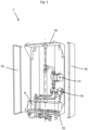
- Figure 3 shows a support device 7 of the hybrid system 1 from a front view and Figure 4 shows the support device 7 of the hybrid system 1 from a rear view.
- figure 4 shows the master control unit 2 that is arranged in an inner space of the support device 7.
- the support device 7 comprises a housing 10 that is formed by several panels, namely a top panel, a bottom panel and two side panels.
- the panels delimit the inner space of the support device 7 in which the pump 11, the distributor 6 and the valve 14 are arranged.
- the distributor 6 is arranged on the bottom panel.
- the housing 10 is attached to a wall.
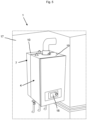
- Figure 5 shows the support device 7 and a second type of heat generator 4 in an assembled state.
- the support device 7, in particular the housing 10, is attached to a wall 17. Additionally, the support device 7 supports the second type of heat generator 4.
- a housing 19 of the second type of heat generator 4 is mechanically connected to the housing 10 of the support device 7.
- an end of the housing 10 is connected to the wall 17 and another end of the housing 10 is connected to the housing 19 of the second type of heat generator 4.
- the second type of heat generator 4 comprises a human machine interface 18 via which the installer can input information.
Landscapes
- Engineering & Computer Science (AREA)
- Physics & Mathematics (AREA)
- Thermal Sciences (AREA)
- Chemical & Material Sciences (AREA)
- Combustion & Propulsion (AREA)
- Mechanical Engineering (AREA)
- General Engineering & Computer Science (AREA)
- Computer Hardware Design (AREA)
- Steam Or Hot-Water Central Heating Systems (AREA)
Abstract
The invention relates to amethod for configuring a hybrid system (1), which comprisesa first type of heat generator (3), in particular heat pump,a master control unit (2) configured to control the first type of heat generator (3),a second type of heat generator (4), in particular a combustion appliance, anda slave control unit (5) configured to control the second type of heat generator (4), whereinthe method comprises the steps thata configuration control unit (20) receives information about the configuration status of the first type of heat generator (3) and of the second type of heat generator (4) anddefines the configuration order.
Description
- The invention relates to method for configuring a hybrid system. Additionally, the invention relates to a configuration control device for carrying out said method and a hybrid system comprising such a configuration control device. The invention also relates to a computer program product, a non-transitory computer readable medium and data carrier signal.
- Heat pumps are becoming more and more popular for heating or cooling of houses and as part of the energy transition as being compatible with current climate targets. Heat pumps are seen as one of the central technologies in the global transition to secure and sustainable heating. As part of the energy transition requirements and regulations, a large number of replacement and upgrading of existing installations is expected, which leads to a need that also installers who are trained in boiler installations, only, need to be able to upgrade or replace an existing boiler installation without the need for refrigeration system mechatronic training and certification. Heat pumps can also be used in addition to or in combination with a combustion appliance like a boiler. Using a heat pump in combination with a combustion appliance is referred to as a 'hybrid system'. Typically, the term hybrid system describes fitting a heat pump alongside a natural gas, LPG or oil boiler. Such hybrid systems comprise a heat pump and a combustion appliance unit that comprises a combustion appliance device for heating a liquid like water. Hybrid heating systems for example are a good option if the installation of a heat pump is possible in principle, but the building still has a higher heating demand until an energy-efficient renovation is carried out, wherein the heating demand is difficult to cover with the heat pump, especially at peak times.
- As a consequence of the role of heat pumps in the transition to secure and sustainable heating, there is a high demand for heat pumps resulting in that heat pump manufacturers cannot meet the market demand. Additionally, there is a lack of heat pump installers, in particular installers who are trained on refrigeration system mechatronics including the required certifications, so that lead times can be long until the heat pump is installed in a house. This results in that the heat pumps or hybrid systems cannot be installed due to the aforementioned problems even though there is a high market demand for heat pumps and hybrid systems.
- The object of the invention is therefore to provide a method by means of which at least a partial hybrid system can be installed and is operational for heating independent of the availability or operability of heat pumps and/or heat pump installers trained on refrigeration system mechatronics including the required certifications at the time of commissioning and preparing the heating system to be compatible with climate target regulation.
- This object is solved by a method for configuring a hybrid system, which comprises a first type of heat generator, in particular heat pump, a master control unit configured to control the first type of heat generator, a second type of heat generator, in particular a combustion appliance, and a slave control unit configured to control the second type of heat generator, wherein the method comprises the steps that a configuration control unit receives information about the configuration status of the first type of heat generator and of the second type of heat generator and defines the configuration order.
- It is realized that it is possible to install and configure an at least partially installed hybrid system even if it does not comprise a first heat generator at the time of configuring, in particular a heat pump, if a configuration control unit is used. This also applies for combustion appliances which are retrofitted to become a hybrid system. In the invention it is realized that hybrid systems can be easily configured when a configuration control unit is used which asks for the configuration status of the components of the hybrid system, in particular of the configuration status of the master control unit and/or the fist type of heating generator and/or the second type of heating generator. By asking about the configuration status, it is easily known which components, in particular which control unit and/or which heat generator, are in the hybrid system. Additionally, the configuration status provides information whether a configuration of the control unit and/or the heat generator assigned to the respective control unit is necessary.
- The second type of heat generator can be configured independent of whether the hybrid system comprises the first type of heat generator or not.
- Such a hybrid system has the advantage that the hybrid system can be installed at e.g. a house even if it does not comprise a first type of heat generator, such as a heat pump at the time of first installation of the partial hybrid system. In this application a partial hybrid system is a system which comprises one type of heat generator and means to control both the one type of heat generator, such as a combustion appliance and a further type of heat generator. The system preferably further comprises means to fluidically connect a further type of heat generator, such as a heat pump, in particular an outdoor unit of a heat pump with the comprised heat generator, in particular the combustion appliance. Thus, it is not necessary to wait that a heat pump is available to be delivered and prepare to be or be compliant with climate target regulation. Additionally, the installer does not need to be certified to install heat pumps to install the at least partial hybrid system when the hybrid system does not comprise the heat pump. The inventive hybrid system has the advantage that it can be installed initially with only one type of heat generator, namely the second type of heat generator. Said at least partial hybrid system can be installed by an installer that is specialized on said second type of heat exchanger. Additionally, the heat pump can be installed at a later time if not available at the time of initial installation of the (partial) hybrid system and/or when the installer has time to install it. The user can flexibly decide if and when the other type of heat generator, namely the first type of heat generator, shall be installed and yet can prepare his heating system to be compliant with applicable climate regulations.
- The fist type of heat generator differs from the second type of heat generator. Specifically, the first type of heat generator can be a heat pump and the second type of heat generator can be a combustion appliance.
- With "heat generator" it is meant an appliance which is configured such that generated heat is transferred to a liquid that flows in a circuit of the heat generator.
- The master control unit is used to control the operation of the hybrid system, i.e. the operation of the first heat generator and/or the second heat generator during the operation of the hybrid system. Said operation commences after a configuration process in which the configuration control unit is used to configure the hybrid system. The operation of the hybrid system can be interrupted and switched to the configuration mode if needed. This can happen when a first type of heat generator is connected to the components of the hybrid system. In said case the master control unit and the first type of heat generator have to be configured.
- The configuration of the master control unit is necessary as the master control unit controls the hybrid system and thus has to know which heat generators are present.
- Using the control unit assigned to the first type of heat generator as master control unit also enables to retrofit existing second type of heat generators to be part of a hybrid system. In said case the master control unit ensures that the control unit of the second type heat generator to be retrofitted is the slave control unit.
- With "defining the configuration order" it is meant the configuration order according to which the control unit, in particular the master control unit, and heat generator are configured.
- According to the understanding of the invention a "combustion appliance device" is any device that is capable to combust fuel. The fuel can be oil, natural gas, propane, hydrogen or a mixture of hydrogen and another fuel, such as natural gas or propane. However, it is also possible that the fuel is in solid state. In said case the fuel can be coal, pellets or the same. The device can be a boiler and/or comprise a burner, a burner chamber and the heat exchanger. Additionally, the device, in particular boiler, can comprise valves, at least one control unit and a control panel.
- The heat pump unit can be a ground source heat pump or an air source heat pump. Additionally or alternatively, the heat pump can be a split unit or a monobloc unit. The heat pump can be configured to heat or cool the fluid medium. Thereto, the heat pump comprises a heat pump heat exchanger in which the heat exchange between the fluid medium and the refrigerant of the heat pump occurs.
- The hybrid system can comprise merely one first type heat generator and merely one second type of heat generator. Thus, the hybrid system does not comprise several heat generators of the first type and/or of the second type. Such a hybrid system has a simple structure.
- The master control unit and/or the slave control unit can comprise one or more processors or be a processor. Alternatively, the master control unit can and/or slave control unit can be a control board circuit or can be part of a control board circuit. Any or all sensors, pumps, actuators, room units of the first type of heat generator can be connected to the master control unit, wirelessly or via electric lines. Likewise, any or all sensors, pumps, actuators, room units of the first type of heat generator can be connected to the slave control unit, wirelessly or via electric lines.
- According to an embodiment the configuration status can be received after the configuration control unit is connected to the master control unit and/or to the slave control unit. The configuration control unit can be wirelessly connected to the master control unit/or to the slave control unit. Alternatively, the configuration control unit can be connected to the master control unit and/or the slave control unit via an electrical line, in particular a data bus connection. The configuration status can be queried from the configuration control unit. This can happen after a configuration mode is started in the configuration control unit, wherein the configuration mode can be started by activating a configuration application that is executed on the configuration control unit.
- The configuration control unit can be configured before the master control unit and/or the at least one heat generator, and/or the slave control is configured. This simplifies the configuration process as configuration control unit can be configured according to the installers needs. For example, the language, used during the configuration process and for operation thereafter, and/or date, time or country can be selected by the installer during the configuration of the configuration control unit.
- In a further embodiment, it is determined - as a further step - whether the first type of heat generator is already configured. Additionally or alternatively it is determined whether the first type of heat generator is defined as not present. The absence of the first type of heat generator can be indicated in the configuration by setting a parameter defined to for example indicate no flow volume from the first type heat generator to the hybrid system. Alternatively the absence of the first type of heat generator can be automatically detected. This can be realized by detecting whether first type of heat generator sends a presence signal. If said presence signal is not detected, it is determined that the first type of heat generator is not present.
- Additionally or alternatively, it is determine whether the second type of heat generator is already configured. This is possible when the control unit is configured before the present configuration. Said information can be obtained from the configuration status that is received by the configuration control unit. That means, the configuration control unit can obtain from the configuration status information whether a control unit, in particular the master control unit, and/or a heat generator is present and whether said control unit and/or heat generator are already configured. By checking the configuration status, it can be avoided to configure the control unit twice.
- The master control unit can be configured first and/or can be configured before the at least one heat generator and/or the slave control unit. As the master control unit controls the operation of the hybrid system during the operation of the hybrid system, by configuring the master control unit at first, it is ensured that no unexpected situation can arise.
- According to an embodiment, the configuration control unit can receive configuration data for configuring the configuration control unit during the configuration process. The installer can provide the configuration data by entering it into the configuration control unit. The configuration data can be information about the language to be used during the configuration mode, the time, the date and the country. After said data is received, the configuration of the configurating control unit is finalized. The hybrid system, in particular the configuration control unit, can be restarted.
- Additionally or alternatively, configuration data for configuring the master control unit can be received during the configuration process. The configuration data can comprise at least one parameter of the heat generator. The at least one parameter can comprise information about the power of the heat generator and/or manufacturer of the heat exchanger. It is possible that further parameters are provided and thus received. Suitable parameters comprise information such as whether a heat exchanger, in particular of the second heat generator, is an aluminum heat exchanger or stainless steel, whether the second heat generator has a gas adaptive control or not. The suitable parameter can further comprise factory settings of parameters, such as how many zones are activated, standard setting for room setpoint for heating curve or the like. The master control unit is configured on the basis of the received configuration data. Afterwards, the hybrid system, in particular the master control unit, is restarted. That means, it is restarted before the heat generator is configured.
- The received configuration data received during the configuration process can be provided by the installer. Specifically, the installer can enter said data into an application that is executed in the configuration control unit.
- According to an embodiment the configuration control unit and/or the master control unit can determine based on the received configuration status whether the hybrid system comprises a first type heat generator. The configuration control unit and/or master control unit can determine that there is no first type of heat generator present if a parameter is received which indicates the absence of the first type of heat generator. Said information can be transmitted to the master control unit. Thus, the master control unit knows at the end of the configuration process whether the hybrid system comprises a first type of heat generator or not.
- A hybrid system according to a first variant can comprise a second type of heat generator and does not comprise a first type of heat generator. The configuration of the second type of heat generator can comprise that a pump for circulating liquid through at least one load circuit is activated. The master control unit can activate said pump. The pump can be activated for performing a de-aeration. Said process can be started automatically when the second type of heat generator shall be configured. Additionally, the configuration process can comprise a functional test of components of the second type of heat generator. With "functional test" it is meant to test whether the component of the second type of heat generator works. The components can be at least one valve and at least one tap. Further, the configuration process can comprise to enter a gas type that is used for combustion. Also, a gas calibration test can be performed in the configuration process. The configuration can also comprise to the process of de-aeration of the circuit of the second type of heat generator. Said process can be controlled by the slave control unit.
- It is also possible that the configuration process comprises further process steps like to check whether the hybrid system comprises an auto filling function. Also it is possible to manually perform load tests and/or configure settings of consumers, in particular defining a heating cur, time programs, etc. Additionally, a hydronic balancing activation can be performed in the configuration process.
- The aforementioned hybrid system according to the first variant i comprises a second type of heat generator that was not configured before and no first type of heat generator. The absence of the first type of heat generator can be indicated in the configuration by setting a parameter defined to for example indicate no flow volume from the first type heat generator to the hybrid system. This first variant is therefore a partial hybrid system within the meaning of this application. In a hybrid system according to a second variant which differs from the hybrid system according to the first variant in that the hybrid system also comprises a first type of heat generator, the first type of heat generator has also to be configured during the configuration process. This configuration comprises activating a further pump of the circuit of the first type of heat generator. That means, said further pump pumps liquid within the circuit of the first type of heat generator. All other configuration steps correspond to the steps mentioned before for the first variant.
- It is also possible to configure a hybrid according to a third variant. Said third variant of the hybrid system differs from the first variant in that it comprises a second type of heat generator that is already configured. That means, the second type of heat generator is retrofitted to become a heat generator of a hybrid system. The configuration process differs from the configuration process for the hybrid system according to the first variant in that the configuration process for the second type heat generator does not require a functional test of the second heat generator. In other words, it is not necessary to configure the gas type, check the valve and tap of the secondary heat generator, de-airation of the second heat generator, flue system, gas pressure, consumer valves and taps check and/ or gas calibration. These functional test steps do not need to be re-done in the third variant for the second type of heat generator. The configuration process comprises that the configuration process for the second type of heat generator comprises the activation of the pump for circulating liquid through at least one load circuit by the master control unit.
- It is also possible to configure a hybrid system according to a fourth variant. The fourth variant differs from the third variant in that it comprises a first type of heat generator. Likewise to the hybrid system according to the third variant, the functional test for the second heat generator type is not required. The configuration of the first type of heat generator is identical to the configuration discussed for the hybrid system according to the second variant.
- The master control unit and the slave control unit can be connected to each other via a data bus. This enables a data communication between the master control unit and the slave control unit. The connection between the master control unit and the slave control unit can be releasable. Both control units are active during the configuration process independent of whether the hybrid comprises the first type of heat generator and the second type of heat generator or only the second type of heat generator.
- The master control unit and the slave control unit can be arranged in different units of the hybrid system. Specifically, the master control unit can be arranged in an inner space of a support device of the hybrid system. Alternatively, the master control unit and/or the slave control unit and/or the configuration control unit can be arranged on one unit of the hybrid system, in particular the master control unit and the configuration control unit can be arranged on one unit. The support device is used to support the combustion appliance. The slave control unit can be arranged in an inner space of the combustion appliance.
- The configuration control unit can correspond to a human machine interface of the hybrid system. The human machine interface can be part of the first type of heat generator. Alternatively, the human machine interface can be part of the second type of the heat generator. It is also possible that the first type of heat generator and the second type of heat generator comprise a human machine interface, respectively. The installer can use the human machine interface to input at least a part of the commissioning data. At least some of the configuration data mentioned above can be stored in an electric memory of the hybrid system.
- Alternatively, the configuration control unit corresponds to an electric device, in particular a mobile electric device. A mobile electric device is a device that an installer can carry to the place where the hybrid system shall be configured and by means of which instructions can be transmitted to the hybrid system. In particular, an application, in particular the computer program product mentioned below, can be executed on the electric device in which the installer can input at least a part of configuring data. Additionally, some remaining configuration data can be stored in the electric device. The configuration data can be transferred to the hybrid system, in particular to the master control unit. In particular, the electric device can be a mobile phone a tablet, a laptop or a computer. An electric device can also be configured to allow for remote configuring of the hybrid system.
- It is also possible that the commissioning data is inputted to the hybrid system, in particular to the master control unit, by means of a data processing device. The data processing device can be connected to the master control unit so that a data exchange between the data processing device and the master control unit is possible. The connection can be via cable or wireless. The data processing unit can be an electric device, in particular a computer or a tablet or a mobile phone, by means of which instructions can be transmitted to the hybrid system. In particular, an application can be executed on the data processing device in which the installer can input commissioning data. Said data can be transferred to the hybrid system, in particular to the master control unit.
- According to an embodiment after the hybrid system is configured, i.e. after the configuration process of the first type of heat generator and the master control unit and/or second type of heat generator and the slave control unit is finalized, the master control unit can process a heat request independent of whether the hybrid system comprises the first type of heat generator or not. If the hybrid system does not comprise the first type of heat generator, the master control unit ensures that all requested heat is provided by the second type of heat generator.
- In some jurisdictions, such as Germany, climate regulation now requires that e.g. in principle, 65 percent of the heat demand must be covered by renewable energies. When it comes to hybrid heating, the currently available renewable energy regulation allows for a simplification. For example, compliance with the 65 percent obligation is assumed for a hybrid heating system consisting of fossil gas or oil boilers in combination with an electric heat pump, provided that the power share of the heat pump is 30 percent or higher. The 65 percent refers to the heat demand in the house, in other words heat actually consumed, which can be expressed in kilowatt hours (heat demand or heat consumption = power multiplied by the running time of the heating system). Buildings lose less heat and thus a lower power of the heating is enough to bring all rooms to comfortable temperatures. As a result, the output of the renewable energy heating system is usually less than 65 percent of the heating load. Proof of fulfilling this requirement can be provided by an energy consultant in accordance with the requirements of DIN V 18599. In case of the hybrid system, a heat pump output of 30 percent of the heating load is sufficient (in accordance with to the partial load point "A" according to DIN EN 14825). The 30 percent refers to the output or the share of the heating load, which can be specified in kilowatts.
- According to a further aspect of the invention a hybrid system is provide. The hybrid system can comprise a first type of heat generator, a master control unit configured to control the first type of heat generator, a second type of heat generator and a slave control unit configured to control the second type of heat generator, wherein the master control unit comprises means for carrying an inventive method.
- According to an embodiment, the hybrid system is configured to have an operation mode, where the first type of heat generator and/or the second type of heat generator is selected dependent on an outside air temperature and/or an outlet temperature of a load circuit liquid and/or a threshold value of at least 2,5 COP for the first type of heat generator.
- The operation mode can optionally comprise that the first type of heat generator or second type of heat generator, in particular selectively, selected
- a) such that in a first operation mode the second type of heat generator is operated and the first type of heat generator is deactivated when the outside air 0 °C, in particular -4 °C, in particular -5 °C, in particular -7°C, in particular -10 °C or less; and/or
- b) such that in a first operation mode the first type of heat generator is operated and the second type of heat generator is deactivated or only provides peak load coverage when the outside air temperature is greater than -10 °C, in particular - 7 °C ,in particular -5 °C, in particular -4 °C, in particular 0 °C and the outlet temperature of the load circuit liquid is less than 55 °C, in particular less than 52 °C, in particular less than 50 °C, in particular less than 45 °C, in particular less than 35 °C; and/or
- c) such that in a first operation mode the second type of heat generator is operated and the first type of heat generator is deactivated when the outlet temperature of the load circuit liquid is 35 °C, in particular, 45 °C , in particular 50°C, in particular 53 °C , in particular 55 °C or greater.
- The operation mode can further comprise that the first type of heat generator and/or the second type of heat generator is selected such that a heat load of the first type of heat generator is at least 30% of the heat load of the hybrid system at 2 °C outside air temperature and 35 °C outlet temperature of the load circuit liquid.
- The hybrid system can comprise a support unit. The support unit can comprise an inner space in which the master control unit is arranged. Additionally or alternatively, the support unit can comprise a distributor by means of which the first type of heat generator and the second type heat generator are fluidically connected to each other.
- The fluid distributor is used to collect and distribute the fluid that flows between the different components of the hybrid system. In particular, the fluid distributor is a hydronic or hydraulic distributor by means of which the fluid, in particular water, as an energy carrier, is distributed between the heat pump unit, the combustion appliance device and at least one load, in particular several loads. The terms hydraulic and hydronic are used as synonymously. The distributor is fluidly connected with the first type of heat generator and the second type of heat generator to receive fluid medium from the first type of heat generator and the second type of heat generator that is to be distributed to the one or more load circuits of the hybrid system. The load circuit can be a central heating circuit. Additionally or alternatively the load circuit can be domestic hot water circle. The fluid distributor has a cavity for receiving the fluid and several inlets and outlets that are fluidically connected to the components of the hybrid.
- A "fluidic connection" between two or more components means that the components are connected in such manner that a fluid, in particular a liquid, can flow from one component to the other component. A "fluid path" is the path that the fluid medium flows within the heating or cooling system. As is discussed below more in detail the heating or cooling system comprises several circuits. Said circuits define the fluid path of the fluid medium.
- The support unit can comprise a housing that supports the second type of heat generator. Said housing can be attached to a wall, in particular to a wall in a building. The housing can be formed by one or more side panels. The side panels can comprise at least one of steel, aluminium, a polymeric, in particular a thermoplastic material, and a composite material or can be made of steel, aluminium, a polymeric, in particular a thermoplastic material, and a composite material. Steel provides the side panels with strength. The aluminium, the polymeric, in particular the thermoplastic material, and the composite material may be used to reduce the noise generated by the hybrid system and reduce the weight of the respective unit.
- According to an aspect of the invention a computer program product is provided. The computer program product comprises instructions which, when the program is executed by a computer, in particular a control unit, cause the computer, in particular the control unit, to carry out an inventive method. Additionally, a non-transitory computer readable medium is provided wherein the non-transitory computer readable medium has stored thereon the inventive computer program product. Further, a data carrier signal carrying the inventive computer program product is provided.
- In the figures, the subject-matter of the invention is schematically shown, wherein identical or similarly acting elements are usually provided with the same reference signs.
- Figure 1
- shows a hybrid system according to the invention.
- Figure 2
- shows a flow chart regarding to a commissioning of the hybrid system shown in
figure 1 . - Figure 3
- shows a support device of the hybrid system from a front view.
- Figure 4
- shows the support device of the hybrid system from a rear view.
- Figure 5
- shows a support device and a second type of heat generator in an assembled state.
- A
hybrid system 1 as shown infigure 1 comprises a first type ofheat generator 3, amaster control unit 2 configured to control the first type ofheat generator 3, a second type ofheat generator 4 and aslave control unit 5 configured to control the second type ofheat generator 4. Themaster control unit 2 and theslave control unit 5 are electrically connected to each other such that a data exchange between the two control units is possible. In this embodiment the first type ofheat generator 3 is a heat pump and the second type ofheat generator 4 is a combustion appliance, in particular a gas boiler. - As is explained in
figure 2 more in detail, themaster control unit 2 receives commissioning data relating to thehybrid system 1 and transmits said received commissioning data to theslave control unit 5 for commissioning the second type ofheat generator 4 independent of whether thehybrid system 1 comprises the first type ofheat generator 3 or not. - The
hybrid system 1 also comprises asupport device 7 that is shown infigures 3 to 5 more in detail. Saidsupport device 7 is used to support the second type ofheat generator 4 and can be attached to a wall. - A
distributor 6 of thehybrid system 1 is arranged in an inner space of thesupport device 7. Thedistributor 6 has a plurality of inlet and outlet connections by means of which a non-shown cavity of thedistributor 6 is fluidically connected to the other components of thehybrid system 1. Thedistributor 6 is fluidically connected to the first type ofheat generator 3 and to the second type ofheat generator 4. Additionally, thedistributor 6 is fluidically connected to afirst load circuit 12 and to asecond load circuit 13. Thefirst load circuit 12 can be a domestic hot water circuit and thesecond load circuit 13 can be a central heating circuit. Thedistributor 6 is used to fluidically connect the first type ofheat generator 3, the second type ofheat generator 4, thefirst load circuit 12 and thesecond load circuit 13 to each other. - The
hybrid system 1 comprises apump 11. Thepump 11 is used to pump liquid within the first and/orsecond load circuit pump 11 is arranged downstream thedistributor 6. Thepump 11 is also arranged within the inner space of thesupport device 7. - The
hybrid system 1 comprises avalve 14. Thevalve 14 is arranged within the inner space of thesupport device 7 and arranged downstream thepump 11. The flow rate flowing within thefirst load circuit 12 or within thesecond load circuit 13 depends on a valve position. Themaster control unit 2 is connected with thevalve 14 and controls the valve position. - The first type of
heat generator 3, which in this embodiment is a heat pump, is only schematically shown. Specifically, the components of the heat pump like compressor, condenser, evaporator and expansion valve are not shown. Additionally, only the part of aheat pump circuit 15 is shown that is fluidically connected with thedistributor 6. However, a further pump that is arranged in theheat pump circuit 15 to ensure circulation of the liquid within theheat pump circuit 15 is not shown. - The second type of
heat generator 4, which in this embodiment is a combustion appliance, in particular a gas boiler, is only schematically shown. In particular, a burner, valves and the heat exchanger of the combustion appliance are not shown. A part of thecombustion appliance circuit 16 that is fluidically connected todistributor 6 is shown. Additionally, another pump is not shown wherein the other pump is used for circulating the liquid within thecombustion appliance circuit 16. - The
hybrid system 1 comprises aconfigurating control unit 20 that can be connected to themaster control unit 2 and/or theslave control 5. The connection can be a data connection and can be wireless. A computer program product is executed on theconfigurating control unit 20 by means of which the components of thehybrid system 1 can be configured as it is explained infigure 2 . -
Figure 2 shows a flow chart regarding to commissioning of thehybrid system 1 shown infigure 1 . In a first step S1 the configuration of thecontrol unit 20 implements a data connection to themaster control unit 2 and/or theslave control unit 5. Additionally, it is possible in the first step to configure theconfiguration control unit 5. In particular, the installer can enter the language to be used during the configuration process, the time, the date and the country in which the hybrid system is located. - In the second step S2 a configuration status is received and a configuration order is determined. In particular, it is determined that the
master control unit 2 is firstly configured and/or that themaster control unit 2 is configured before thesecond control unit 5 and theheat generators master control unit 2 can transmit a master signal to all connected units so that each unit knows that the master control unit is the master of thehybrid system 1. Additionally, themaster control unit 2 can ensure that all central heating zones that are provided by the second type of heat generator are deactivated. - In a third step S3 the
master control unit 2 is configured. Thereto themaster control unit 2 receives configuration data. Themaster control unit 2 receives said data from theconfiguration control unit 20. In said case the installer inputted said information into the application executed on theconfiguration control unit 20. Additionally or alternatively, themaster control unit 2 can directly receive the configuration data from theslave control unit 5. The configuration data can comprise information about the type of the second type ofheat generator 4, in particular about the power of the second type of heat generator. After themaster control unit 2 is configured the hybrid system, in particular its components, are restarted. - In a fourth step S4 it is determined whether the
hybrid system 1 comprises the first type ofheat generator 3. Said determination can be done by themaster control unit 2 and/or by theconfiguration control unit 20. - The outcome of the determination can be one of the four possible hybrid system variants. According to a first variant, the
hybrid system 1 does not comprise a first type ofheat generator 3 but comprises a second type ofheat generator 4 that was not configured before. According to second variant, thehybrid system 1 comprises a first type ofheat generator 3 and a second type ofheat generator 4 that was not configured before. According to a third variant, thehybrid system 1 does not comprise a first type ofheat generator 3 but comprises a second type ofheat generator 4 that was configured before. According to a fourth variant, thehybrid system 1 comprises a first type ofheat generator 3 and a second type ofheat generator 4 that was configured before. - If the
hybrid system 1 comprises a first type ofheat generator 3, the steps S5, S6 and S7 are performed. If thehybrid system 1 does not comprise a first type ofheat generator 3, the steps S8 and S7 are performed. - In the following, the configuration process is explained for the first variant and the third variant of the
hybrid system 1. As mentioned above the first variant of thehybrid system 1 does not comprise a first type of heat generator and comprises second type of heat generator that was not configured before. Thus, in the eight step S8 the second type ofheat generator 4 is configured. Thereto, the master control device activates thepump 11 for circulating liquid through at least oneload circuit load circuits - Additionally, further steps can be performed during the configuration process in steps S8. Said steps can be to perform a functional test of components of the second type of heat generator. With "functional test" it is meant to test whether the component or components of the second type of heat generator works. The components can be at least one valve and tap. Further, the configuration process can comprise that the installer enters a gas type that is used for combustion. Also, a gas calibration test can be performed in the configuration process. The configuration can also comprise to the process of de-aeration of the circuit of the second type of heat generator. Said process can be controlled by the
slave control unit 2. - It is also possible that the configuration process comprises further process like to check whether the hybrid system comprises an auto filling function. Also it is possible to manually perform load tests and/or configure settings of consumers, in particular defining a heating cur, time programs, etc. Additionally, a hydronic balancing activation can be performed in the configuration process.
- The configuration process for the third variant of the
hybrid system 1 differs from the first variant in that there is no need to perform a functional test of components of the second type of heat generator and/or to enter a gas type that is used for combustion. Also, it is not necessary to perform the gas calibration test and to de-aerate the circuit of the second type of heat generator. Additionally, it is not necessary to check whether the hybrid system comprises an auto filling function. - However, likewise to the first variant the configuration process of the third variant comprises to activate the pump for performing de-aeration in the load circuit. Likewise, to the first variant, it is possible that the configuration process comprises to manually perform load tests and/or configure settings of consumers, in particular, defining a heating curve, time programs, etc. Additionally, a hydronic balancing activation can be performed in the configuration process.
- After the eight step S8 the commissioning is finalized and the hybrid control system is switched to a normal operation mode in a seventh step S7. In the normal operation mode the
master control unit 2 and theslave control unit 5 ensure that the heat request coming from the loads of the first and/orsecond load circuit heat generator 3 and/or second type ofheat generator 4. - In the following, the configuration process is explained for the second variant and the fourth variant of the
hybrid system 1. As mentioned above the second variant of the hybrid system comprises a first type ofheat generator 3 and comprises the second type ofheat generator 4 that was not configured before. - Thus, in the fifth step S5 the first type of
heat generator 4 is configured. Thereto, themaster control unit 5 activates the further pump. The further pump is the pump that ensures liquid circulation within the circuit of the first type of heat generators. - In a sixth step S6, the second type of heat generator is configured. The configuration of the second type of
heat generator 4 is identical to the configuration process explained above for the first variant. - Likewise, to the first variant, it is possible that the configuration process of the hybrid system according to the third variant comprises to manually perform load tests and/or configure settings of consumers, in particular defining a heating curve, time programs, etc. Additionally, a hydronic balancing activation can be performed in the configuration process.
- The configuration process for the fourth variant of the
hybrid system 1 does not differ from the second variant regarding the configuration of the first type of heat generator. Therefore, it is referred to the statement above. - The configuration process regarding the second type of heat generator does not differ from the configuration process for the second type of the heat generator of the hybrid system according to the third variant. Thus, it is referred to the aforementioned description.
- Likewise, to the first variant, it is possible that the configuration process of the hybrid system according to the third variant comprises to manually perform load tests and/or configure settings of consumers, in particular defining a heating cur, time programs, etc. Additionally, a hydronic balancing activation can be performed in the configuration process.
- The fifth and sixth step S5, S6 can be done in parallel. Alternatively, in a non-shown embodiment the sixth step can be done before the fifth step.
-
Figure 3 shows asupport device 7 of thehybrid system 1 from a front view andFigure 4 shows thesupport device 7 of thehybrid system 1 from a rear view. In contrary tofigure 3 ,figure 4 shows themaster control unit 2 that is arranged in an inner space of thesupport device 7. - The
support device 7 comprises ahousing 10 that is formed by several panels, namely a top panel, a bottom panel and two side panels. The panels delimit the inner space of thesupport device 7 in which thepump 11, thedistributor 6 and thevalve 14 are arranged. Thedistributor 6 is arranged on the bottom panel. As is evident fromfigure 5 , thehousing 10 is attached to a wall. -
Figure 5 shows thesupport device 7 and a second type ofheat generator 4 in an assembled state. Thesupport device 7, in particular thehousing 10, is attached to awall 17. Additionally, thesupport device 7 supports the second type ofheat generator 4. Specifically, ahousing 19 of the second type ofheat generator 4 is mechanically connected to thehousing 10 of thesupport device 7. Thus, an end of thehousing 10 is connected to thewall 17 and another end of thehousing 10 is connected to thehousing 19 of the second type ofheat generator 4. The second type ofheat generator 4 comprises ahuman machine interface 18 via which the installer can input information. -
- 1
- Hybrid system
- 2
- Master control unit
- 3
- First type of heat generator
- 4
- Second type of heat generator
- 5
- Slave control unit
- 6
- Distributor
- 7
- Appliance unit
- 8
- First load circuit
- 9
- Second load circuit
- 10
- Housing
- 11
- Pump
- 12
- First load circuit
- 13
- Second load circuit
- 14
- Valve
- 15
- Heat pump circuit
- 16
- Combustion appliance circuit
- 17
- Wall
- 18
- Human machine interface
- 19
- Housing of second type of heat generator
- 20
- Configuration control unit
Claims (15)
- Method for configuring a hybrid system (1), which comprisesa first type of heat generator (3), in particular heat pump,a master control unit (2) configured to control the first type of heat generator (3),a second type of heat generator (4), in particular a combustion appliance, anda slave control unit (5) configured to control the second type of heat generator (4), whereinthe method comprises the steps thata configuration control unit (20) receives information about the configuration status of the first type of heat generator (3) and of the second type of heat generator (4) and defines the configuration order.
- Method according to claim 1, characterized in that the configuration status is received after the configuration control unit (20) is connected to the master control unit (2) and/or to the slave control unit (5).
- Method according to claim 1 or 2, characterized in that the configuration control unit (20) is configured before the master control unit (2) and/or at least one heat generator (3, 4) and/or the slave control (5) is configured.
- Method according to at least one of the claims 1 to 3, characterized in that it is determined whethera. the first type of heat generator (3) is already configured and/orb. the first type of heat generator is defined as not present and/orc. the second type of heat generator (4) is already configured.
- Method according to at least one of the claims 1 to 4, characterized in that the master control unit (2) is configured before the heat generator (3, 4) and/or the slave control unit (5) is configured.
- Method according to at least one of the claims 1 to 5, characterized in thata. configuration data for configuring the master control unit (2) is received, wherein the configuration data comprises at least one parameter of the heat generator (3,4) and/or in thatb. configuration data for configuring the configuration control unit (20) is received.
- Method according to at least one of the claims 1 to 6, characterized in thata. the configuration of the first type heat generator (3) comprises sending an activation signal to a pump of the circuit of the second type of heat generator (4) and/or in thatb. the configuration of the second type of heat generator (4) comprises sending an activation signal to a pump (11) of the hybrid system (1) and/or a functional test of components of the second type of heat generator (4).
- Method according to at least one of the claims 1 to 7, characterized in that based on the received configuration status information it is determined whether the hybrid system (1) comprises a first type heat generator (3).
- Method according to at least one of the claims 1 to 8, characterized in that after the hybrid system (1) is configured, the master control unit (2) processes a heat request independent of whether the hybrid system (1) comprises the first heat generator (3) or not.
- Configuration control unit (20) for configuring the hybrid system (1) wherein the configuration control unit (20) comprising means for carrying out the method of at least one of the claims 1 to 9, in particular wherein the commissioning control unit (20) corresponds to a human machine interface (18) of a heat generator (3,4) or to an electric device, in particular a mobile electric device.
- Hybrid System (1) comprising a first type of heat generator (3), master control unit (2) configured to control the first type of heat generator (3), a second type of heat generator (4), a slave control unit (4) configured to control the second type of heat generator (4), and a configuration control unit (20) for configurating the hybrid system (1), wherein the configuration control unit (20) comprises means for carrying out the method of at least one of the claims 1 to 8.
- Hybrid system (1) according to claim 11, characterized in that the hybrid system (1) comprises a support unit (7) whereina. the support unit (7) comprises an inner space in which the master control unit (2) is arranged and/or whereinb. the support (7) unit comprises a distributor (6) by means of which the first type heat of generator (3) and the second type heat generator (4) are fluidically connected and/or whereinc. the support unit (7) comprises a housing (10) that supports the second type of heat generator (4).
- Computer program product comprising instructions which, when the program is executed by a computer, in particular a control unit, cause the computer, in particular the control unit, to carry out the method of at least one of the claims 1 to 9.
- Non transitory computer readable medium having stored thereon the computer program product according to claim 13.
- Data carrier signal carrying the computer program product of claim 13.
Priority Applications (2)
| Application Number | Priority Date | Filing Date | Title |
|---|---|---|---|
| EP23206379.2A EP4545865A1 (en) | 2023-10-27 | 2023-10-27 | Method for configuring a hybrid system |
| PCT/EP2024/080007 WO2025088001A1 (en) | 2023-10-27 | 2024-10-24 | Method for configuring a hybrid system |
Applications Claiming Priority (1)
| Application Number | Priority Date | Filing Date | Title |
|---|---|---|---|
| EP23206379.2A EP4545865A1 (en) | 2023-10-27 | 2023-10-27 | Method for configuring a hybrid system |
Publications (1)
| Publication Number | Publication Date |
|---|---|
| EP4545865A1 true EP4545865A1 (en) | 2025-04-30 |
Family
ID=88598816
Family Applications (1)
| Application Number | Title | Priority Date | Filing Date |
|---|---|---|---|
| EP23206379.2A Withdrawn EP4545865A1 (en) | 2023-10-27 | 2023-10-27 | Method for configuring a hybrid system |
Country Status (2)
| Country | Link |
|---|---|
| EP (1) | EP4545865A1 (en) |
| WO (1) | WO2025088001A1 (en) |
Citations (3)
| Publication number | Priority date | Publication date | Assignee | Title |
|---|---|---|---|---|
| US20120138149A1 (en) * | 2010-12-02 | 2012-06-07 | Takagi Industrial Co., Ltd. | Hot water supply system, water heater and hot water supply control method |
| EP3546839A1 (en) * | 2018-03-26 | 2019-10-02 | Mitsubishi Electric R&D Centre Europe B.V. | Modular routing device for a configurable fluidic coupling of three functional devices with heating and/or cooling circuits |
| DE102020204276A1 (en) * | 2020-04-02 | 2021-10-07 | Robert Bosch Gesellschaft mit beschränkter Haftung | Heating device and method for operating a heating device |
-
2023
- 2023-10-27 EP EP23206379.2A patent/EP4545865A1/en not_active Withdrawn
-
2024
- 2024-10-24 WO PCT/EP2024/080007 patent/WO2025088001A1/en active Pending
Patent Citations (3)
| Publication number | Priority date | Publication date | Assignee | Title |
|---|---|---|---|---|
| US20120138149A1 (en) * | 2010-12-02 | 2012-06-07 | Takagi Industrial Co., Ltd. | Hot water supply system, water heater and hot water supply control method |
| EP3546839A1 (en) * | 2018-03-26 | 2019-10-02 | Mitsubishi Electric R&D Centre Europe B.V. | Modular routing device for a configurable fluidic coupling of three functional devices with heating and/or cooling circuits |
| DE102020204276A1 (en) * | 2020-04-02 | 2021-10-07 | Robert Bosch Gesellschaft mit beschränkter Haftung | Heating device and method for operating a heating device |
Also Published As
| Publication number | Publication date |
|---|---|
| WO2025088001A1 (en) | 2025-05-01 |
Similar Documents
| Publication | Publication Date | Title |
|---|---|---|
| US11156371B2 (en) | Networked boilers and control method | |
| US20160363335A1 (en) | Multi-Unit Air Conditioning System And A Controlling Method Of Multi-Unit Air Conditioning System | |
| JP5892269B2 (en) | Temperature control system | |
| LU505389B1 (en) | Method for commissioning a hybrid system | |
| WO2025088001A1 (en) | Method for configuring a hybrid system | |
| EP4379266A1 (en) | Hybrid air conditioning and sanitary water heating system | |
| EP3081868B1 (en) | Set and method for assembling a heat source unit of an air conditioner at the site the air conditioner | |
| EP4545866A1 (en) | Method for switching a hybrid system to a chimney sweeper mode | |
| EP3924669A1 (en) | Electric boiler, central heating system comprising an electric boiler, tap water heating system comprising an electric boiler and method for operating the same | |
| EP3869117B1 (en) | Air conditioning device | |
| JP6210019B2 (en) | Hot water storage water heater | |
| WO2024188430A1 (en) | Heat pump coupling frame kit with a receiving slot | |
| WO2024240331A1 (en) | Heat pump coupling frame kit with an aligned connector set | |
| WO2024188438A1 (en) | Heat pump coupling frame kit with an aligned connector set | |
| WO2024188424A1 (en) | Hybrid heat pump frame kit with a jig | |
| EP1033539B1 (en) | Modular collector provided with a system of thermoregulation for heating plants with radiating panels or the like | |
| WO2024188428A1 (en) | Heat pump coupling frame kit with a distributor | |
| WO2024188429A1 (en) | Heat pump coupling frame kit with side panels | |
| WO2024188423A1 (en) | Hybrid heat pump frame kit | |
| WO2025087544A1 (en) | Heat pump coupling frame kit with energy monitoring | |
| EP4677274A1 (en) | Heat pump coupling frame kit with an aligned connector set | |
| WO2024188425A1 (en) | Hybrid heat pump frame kit with a receiving portion | |
| WO2024188434A1 (en) | Hybrid heat pump frame kit with side panels | |
| EP4636321A1 (en) | Connecting assembly for a heat control system | |
| EP4686880A1 (en) | Hybrid system optimized for space heating and/or sanitary water production |
Legal Events
| Date | Code | Title | Description |
|---|---|---|---|
| PUAI | Public reference made under article 153(3) epc to a published international application that has entered the european phase |
Free format text: ORIGINAL CODE: 0009012 |
|
| STAA | Information on the status of an ep patent application or granted ep patent |
Free format text: STATUS: THE APPLICATION HAS BEEN PUBLISHED |
|
| AK | Designated contracting states |
Kind code of ref document: A1 Designated state(s): AL AT BE BG CH CY CZ DE DK EE ES FI FR GB GR HR HU IE IS IT LI LT LU LV MC ME MK MT NL NO PL PT RO RS SE SI SK SM TR |
|
| STAA | Information on the status of an ep patent application or granted ep patent |
Free format text: STATUS: THE APPLICATION IS DEEMED TO BE WITHDRAWN |
|
| 18D | Application deemed to be withdrawn |
Effective date: 20251031 |