EP4545859A1 - Home appliance - Google Patents
Home appliance Download PDFInfo
- Publication number
- EP4545859A1 EP4545859A1 EP24208592.6A EP24208592A EP4545859A1 EP 4545859 A1 EP4545859 A1 EP 4545859A1 EP 24208592 A EP24208592 A EP 24208592A EP 4545859 A1 EP4545859 A1 EP 4545859A1
- Authority
- EP
- European Patent Office
- Prior art keywords
- guide
- wire
- door
- wire guide
- casing
- Prior art date
- Legal status (The legal status is an assumption and is not a legal conclusion. Google has not performed a legal analysis and makes no representation as to the accuracy of the status listed.)
- Pending
Links
Images







Classifications
-
- F—MECHANICAL ENGINEERING; LIGHTING; HEATING; WEAPONS; BLASTING
- F24—HEATING; RANGES; VENTILATING
- F24C—DOMESTIC STOVES OR RANGES ; DETAILS OF DOMESTIC STOVES OR RANGES, OF GENERAL APPLICATION
- F24C15/00—Details
- F24C15/02—Doors specially adapted for stoves or ranges
-
- F—MECHANICAL ENGINEERING; LIGHTING; HEATING; WEAPONS; BLASTING
- F24—HEATING; RANGES; VENTILATING
- F24C—DOMESTIC STOVES OR RANGES ; DETAILS OF DOMESTIC STOVES OR RANGES, OF GENERAL APPLICATION
- F24C15/00—Details
-
- E—FIXED CONSTRUCTIONS
- E05—LOCKS; KEYS; WINDOW OR DOOR FITTINGS; SAFES
- E05D—HINGES OR SUSPENSION DEVICES FOR DOORS, WINDOWS OR WINGS
- E05D11/00—Additional features or accessories of hinges
- E05D11/0081—Additional features or accessories of hinges for transmitting energy, e.g. electrical cable routing
-
- F—MECHANICAL ENGINEERING; LIGHTING; HEATING; WEAPONS; BLASTING
- F24—HEATING; RANGES; VENTILATING
- F24C—DOMESTIC STOVES OR RANGES ; DETAILS OF DOMESTIC STOVES OR RANGES, OF GENERAL APPLICATION
- F24C7/00—Stoves or ranges heated by electric energy
- F24C7/08—Arrangement or mounting of control or safety devices
- F24C7/082—Arrangement or mounting of control or safety devices on ranges, e.g. control panels, illumination
-
- F—MECHANICAL ENGINEERING; LIGHTING; HEATING; WEAPONS; BLASTING
- F24—HEATING; RANGES; VENTILATING
- F24C—DOMESTIC STOVES OR RANGES ; DETAILS OF DOMESTIC STOVES OR RANGES, OF GENERAL APPLICATION
- F24C7/00—Stoves or ranges heated by electric energy
- F24C7/08—Arrangement or mounting of control or safety devices
- F24C7/082—Arrangement or mounting of control or safety devices on ranges, e.g. control panels, illumination
- F24C7/085—Arrangement or mounting of control or safety devices on ranges, e.g. control panels, illumination on baking ovens
-
- F—MECHANICAL ENGINEERING; LIGHTING; HEATING; WEAPONS; BLASTING
- F25—REFRIGERATION OR COOLING; COMBINED HEATING AND REFRIGERATION SYSTEMS; HEAT PUMP SYSTEMS; MANUFACTURE OR STORAGE OF ICE; LIQUEFACTION SOLIDIFICATION OF GASES
- F25D—REFRIGERATORS; COLD ROOMS; ICE-BOXES; COOLING OR FREEZING APPARATUS NOT OTHERWISE PROVIDED FOR
- F25D23/00—General constructional features
- F25D23/02—Doors; Covers
- F25D23/028—Details
-
- F—MECHANICAL ENGINEERING; LIGHTING; HEATING; WEAPONS; BLASTING
- F25—REFRIGERATION OR COOLING; COMBINED HEATING AND REFRIGERATION SYSTEMS; HEAT PUMP SYSTEMS; MANUFACTURE OR STORAGE OF ICE; LIQUEFACTION SOLIDIFICATION OF GASES
- F25D—REFRIGERATORS; COLD ROOMS; ICE-BOXES; COOLING OR FREEZING APPARATUS NOT OTHERWISE PROVIDED FOR
- F25D29/00—Arrangement or mounting of control or safety devices
- F25D29/005—Mounting of control devices
-
- H—ELECTRICITY
- H01—ELECTRIC ELEMENTS
- H01R—ELECTRICALLY-CONDUCTIVE CONNECTIONS; STRUCTURAL ASSOCIATIONS OF A PLURALITY OF MUTUALLY-INSULATED ELECTRICAL CONNECTING ELEMENTS; COUPLING DEVICES; CURRENT COLLECTORS
- H01R13/00—Details of coupling devices of the kinds covered by groups H01R12/70 or H01R24/00 - H01R33/00
- H01R13/46—Bases; Cases
-
- E—FIXED CONSTRUCTIONS
- E05—LOCKS; KEYS; WINDOW OR DOOR FITTINGS; SAFES
- E05Y—INDEXING SCHEME ASSOCIATED WITH SUBCLASSES E05D AND E05F, RELATING TO CONSTRUCTION ELEMENTS, ELECTRIC CONTROL, POWER SUPPLY, POWER SIGNAL OR TRANSMISSION, USER INTERFACES, MOUNTING OR COUPLING, DETAILS, ACCESSORIES, AUXILIARY OPERATIONS NOT OTHERWISE PROVIDED FOR, APPLICATION THEREOF
- E05Y2400/00—Electronic control; Electrical power; Power supply; Power or signal transmission; User interfaces
- E05Y2400/65—Power or signal transmission
- E05Y2400/654—Power or signal transmission by electrical cables
-
- E—FIXED CONSTRUCTIONS
- E05—LOCKS; KEYS; WINDOW OR DOOR FITTINGS; SAFES
- E05Y—INDEXING SCHEME ASSOCIATED WITH SUBCLASSES E05D AND E05F, RELATING TO CONSTRUCTION ELEMENTS, ELECTRIC CONTROL, POWER SUPPLY, POWER SIGNAL OR TRANSMISSION, USER INTERFACES, MOUNTING OR COUPLING, DETAILS, ACCESSORIES, AUXILIARY OPERATIONS NOT OTHERWISE PROVIDED FOR, APPLICATION THEREOF
- E05Y2900/00—Application of doors, windows, wings or fittings thereof
- E05Y2900/30—Application of doors, windows, wings or fittings thereof for domestic appliances
- E05Y2900/308—Application of doors, windows, wings or fittings thereof for domestic appliances for ovens
-
- F—MECHANICAL ENGINEERING; LIGHTING; HEATING; WEAPONS; BLASTING
- F25—REFRIGERATION OR COOLING; COMBINED HEATING AND REFRIGERATION SYSTEMS; HEAT PUMP SYSTEMS; MANUFACTURE OR STORAGE OF ICE; LIQUEFACTION SOLIDIFICATION OF GASES
- F25D—REFRIGERATORS; COLD ROOMS; ICE-BOXES; COOLING OR FREEZING APPARATUS NOT OTHERWISE PROVIDED FOR
- F25D2400/00—General features of, or devices for refrigerators, cold rooms, ice-boxes, or for cooling or freezing apparatus not covered by any other subclass
- F25D2400/36—Visual displays
-
- F—MECHANICAL ENGINEERING; LIGHTING; HEATING; WEAPONS; BLASTING
- F25—REFRIGERATION OR COOLING; COMBINED HEATING AND REFRIGERATION SYSTEMS; HEAT PUMP SYSTEMS; MANUFACTURE OR STORAGE OF ICE; LIQUEFACTION SOLIDIFICATION OF GASES
- F25D—REFRIGERATORS; COLD ROOMS; ICE-BOXES; COOLING OR FREEZING APPARATUS NOT OTHERWISE PROVIDED FOR
- F25D2400/00—General features of, or devices for refrigerators, cold rooms, ice-boxes, or for cooling or freezing apparatus not covered by any other subclass
- F25D2400/40—Refrigerating devices characterised by electrical wiring
Definitions
- the present invention relates to a home appliance.
- Commonly used home appliances such as cooking appliances, refrigerators, and garment care devices, have a door that provides access to an internal space for storing items.
- These appliances typically consist of a cavity exterior with an interior compartment designed for storing objects, along with a door for opening and closing this compartment.
- a touch sensor device for example, a touch sensor device, a display device, a lighting device, communication device, etc. may be installed on the door. These electronic components may be operated by being supplied with power from a main body of the home appliance.
- the electronic components may be electrically connected to a main control part provided in the home appliance body through a wire.
- the wire may be arranged along the inside of a main body of the home appliance to connect between the electronic components of the door and the main control part. Both ends of the wire disposed inside the main body may be connected to the electronic components of the door and the main control part, respectively.
- the wire provided in an electric home appliance with a very high internal temperature such as a cooking appliance equipped with a heating device, may be heated higher than an allowable temperature.
- the wire disposed inside a main body of the home appliance is close to the heating device, so there is a risk that the wire is heated and damaged more easily.
- wires used to connect communication devices or imaging devices are more vulnerable to high-temperature environments because it is difficult to apply high heat-resistant coating due to the nature of the product.
- the wire may be provided along the outer edge of the cavity.
- the wire may be provided along the cavity surface of the home appliance.
- the temperature of the wire may be relatively lowered compared to when the wire is disposed inside the main body of the home appliance, but since the cavity of the home appliance is also made of metal, there is still a problem that heat from the heating device is transmitted to the wire.
- the wire may be arranged around the outer edge of the cavity so as not to be adjacent to the cavity of the home appliance main body.
- the wire may extend from a lower portion of the door along the bottom of the home appliance to the rear of the home appliance.
- the wire extending to the rear of the home appliance moves upward along the rear of the home appliance and may be connected to the main control part.
- the wire is arranged around the outer edge of the home appliance like this, not only does the length of the wire increase, increasing manufacturing costs, but there is also the problem of increased noise in the signal.
- communication devices and imaging devices are sensitive to noise mixed with signals, leading to performance degradation as the length of the wire increases.
- the invention is specified by the independent claim. Preferred embodiments are defined by the dependent claims.
- the present invention has been made in an effort to solve various problems in the prior art, with the objective of providing a home appliance that shortens a wire installation path connecting a main body and a door while also insulating the wire from the heat/cold air of the home appliance transmitted to the wire.
- Another object of the present invention is to prevent wires from being damaged during installing the home appliance on furniture.
- a further object of the present invention is to arrange the wire along a certain installation path inside the home appliance.
- a further object of the present invention is to minimize wire exposure by arranging the wire slightly toward the rear, away from the front of the home appliance.
- a home appliance of the present invention may include a casing having a storage compartment therein.
- a door may be disposed in front of the storage compartment to open and close the storage compartment.
- a first electronic component may be disposed outside the casing.
- a second electronic component may be disposed at the door.
- a wire may electrically connect the first electronic component and the second electronic component.
- a wire guide may be disposed in the casing. In this case, a guide channel in which the wire is stored may be formed inside the wire guide. This helps to prevent the direct transfer of heat/cold air from the home appliance to the wire.
- the wire guide may be disposed on a side surface of the casing in the height direction of the casing.
- the wire guide may be disposed closer to the door than the center of the side surface of the casing.
- An equipment room in which the first electronic component is placed may be provided at an upper portion of the casing.
- the wire guide may be disposed between a first point entering the interior of the equipment room and a second point entering the door.
- the equipment room in which the first electronic component is placed may be provided at the upper portion of the casing.
- One end of the guide channel may be open toward the equipment room.
- the other end of the guide channel may be open toward the lower part of the door.
- a through hole may be open in the upper portion of the casing defining the equipment room.
- the other end of the wire guide may be provided with a guide hole connected to the through hole.
- a guide arm inserted into the through hole protrudes from the other end of the wire guide, and the guide arm may protrude from an edge of the guide hole.
- the wire guide may include a guide base disposed on a side surface of the casing, and a guide cover coupled to the guide base and defining the guide channel together with the guide base.
- the guide base may include a bottom part on which the wire is seated, and a pair of fence parts provided on both sides of the bottom part.
- a partition rib may protrude from the bottom part.
- the partition rib may be disposed between the pair of fence parts.
- the wire guide may include a first guide part extending toward the equipment room where the first electronic component is disposed, and a second guide part provided on the other side of the first guide part and extending toward the door.
- the first guide part and the second guide part may extend in different directions.
- a guide hole that opens toward the equipment room may be open in the first guide part.
- a door connection hole that opens toward a lower part of the door may be open in the second guide part.
- the wire guide may include a first wire guide and a second wire guide arranged at a different height from the first wire guide.
- the first wire guide and the second wire guide may form a continuous guide path.
- a first channel hole and a second channel hole connected to each other may be open at the lower end of the first wire guide and the upper end of the second wire guide facing the lower end of the first wire guide.
- the first wire guide may be provided with a guide hole open toward the equipment room and a door connection hole open toward the lower part of the door.
- the guide hole, the door connection hole, and the first channel hole may be open in different directions.
- a side plate may be provided on the side surface of the casing.
- the side plate may be disposed closer to the door than the wire guide.
- the side plate may protrude more from the side surface of the casing than the wire guide or may form a continuous plane with the wire guide.
- the side plate may be provided with a plate recess part that is recessed toward the side surface of the casing.
- the plate recess part may form a continuous wire path together with the wire guide.
- the casing may be provided with a guide bracket.
- the guide bracket may cover one end of the wire guide.
- the guide bracket may cover one end of the wire guide that is open toward the door.
- the guide bracket may include a bracket body that covers the wire guide
- the guide bracket may include a mounting body that extends from the bracket body toward the door and is fixed to the casing.
- the mounting body may protrude more from the side surface of the casing than the bracket body.
- the casing may be equipped with a guide bracket.
- the guide bracket may cover a portion where the first wire guide and the second wire guide are connected.
- the home appliance according to the present invention as described above has the following effects.
- an electronic component disposed at a door may be connected to a main body of the home appliance through a wire.
- a wire guide is disposed between a casing and the wire to block each other. Accordingly, heat/cold air of the home appliance directly transmitted to the wire may be blocked.
- the insulation function by the wire guide may increase the durability of the wire and the operational reliability of the electronic component.
- the wire guide is disposed on a side surface of the home appliance, and the wire may extend from the side surface of the home appliance to the height direction of the home appliance along the wire guide.
- the wire does not need to extend from the front surface (door) of the home appliance to the rear surface of the home appliance, and thus the entire path of the wire may be shortened.
- the entire path of the shortened wire may reduce noise of a signal transmitted through the wire and improve the quality of the home appliance.
- the wire guide may form a path in which the wire extends. Since the wires may be arranged in a certain path along the wire guide, there is an effect of increasing the convenience of installing the wires. In addition, since the wires have a consistent path, interference with peripheral components may be prevented.
- the wire guide combines a guide base and a guide cover to create a guide channel, and the wire may be stored in the guide channel.
- the influence of surrounding temperature and humidity on the wire is reduced, and foreign substances may be blocked, thereby improving the durability of the wire.
- the wire since the wire may be disposed on the side surface of the casing, compared to installing the wire under the casing or inside a frame, the operation of mounting/removing the wire may be easily performed. In particular, when a guide cover is removed, the wire may be exposed, providing the advantage of easy maintenance.
- connectors coupled to the wire may be assembled or separated from each other at a lower portion of the door located in the front of the home appliance, thereby improving accessibility to the connectors. Accordingly, the process of assembly and disassembly of the connector may be improved.
- the wire may exit from the lower portion of the door and be inserted into an equipment room provided in an upper portion of the home appliance.
- the wire since the wire extends in the vertical direction along the wire guide disposed on the side surface of the casing, the wire may not be exposed to the outside. This helps maintain the aesthetics of the home appliance by preventing the wire from being exposed.
- the wire guide may be partially covered by a guide bracket provided on the side surface of the casing.
- the metal guide bracket protects the wire guide during the process of storing the home appliance inside furniture, etc., and may prevent the wire guide and the built-in wire from being damaged.
- the guide bracket may protrude further from the side surface of the casing than the wire guide.
- the protruding guide bracket may prevent the wire guide from colliding with the surrounding area during the process of storing the home appliance.
- the guide bracket may facilitate storing the home appliance by aligning the left and right sides of the home appliance during the process of storing the home appliance.
- the guide bracket may act as a kind of spacer to maintain a certain distance between the furniture mounting space and the home appliance.
- a plurality of wire guides are connected to each other, and the connected wire guides may form a continuous guide path.
- the plurality of wire guides may insulate the wire provided in a home appliance having a high height. Therefore, the present invention may have compatibility applicable to home appliances of various sizes.
- a side plate may be provided on the side surface of the casing.
- the side plate is provided with a plate recess part, so that a continuous guide path leading to the wire guide may be formed. Accordingly, the wire does not protrude from the side surface of the casing, and the storage capacity of the wire may be improved.
- the wire guide of the present invention may be provided with partition ribs that partition the guide channel.
- the partition rib allows the wire to be aligned in a certain direction inside the guide channel. Therefore, workability of the wire storage may be improved, and the operational reliability may also be improved because the wire does not shake inside the wire guide.
- the present invention relates to a home appliance.
- the home appliance may mean a device that has storage compartments (not shown) therein, and the storage compartments are open and closed by doors 50 and 70.
- the doors 50 and 70 are disposed in front of the storage compartments and may serve to open and close the storage compartments.
- "front” refers to the direction a user faces when the user is positioned in front of the home appliance.
- the X-axis direction may be forward.
- the Y-axis direction may be the width direction of the home appliance.
- the Z-axis direction may be the height direction of the home appliance. The description will be made based on this direction.
- the home appliance may include various home appliances such as cooking appliances, refrigerators, freezers, kimchi refrigerators, plant cultivation devices, stylers, and washing machines.
- a cooking appliance among the home appliances will be described as an example.
- the home appliance may be stored in a built-in manner in furniture.
- the home appliance may be a cooking appliance installed in a built-in manner.
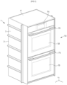
- the cooking appliance of the present embodiment may be installed in a kitchen furniture 1 or the like so that only the front surface of the cooking appliance may be exposed forward.
- doors 50 and 70 and a display part 16 may be included in the front of the cooking appliance.
- the kitchen furniture 1 may include a lower structure 2, a rear surface portion 3, an upper surface portion 4, and a side surface portion 5.
- the home appliance may be surrounded by the rear surface portion 3, the upper surface portion 4, and the side surface portion 5 disposed on the bottom portion thereof, and only the front surface of the home appliance may be exposed forward. Since an area in which the home appliance is exposed forward is small, maintenance of an electronic component of the home appliance may also be performed in a narrow space.
- the door consists of two doors 50 and 70, but it may also be applied to a home appliance provided with only one lower door 70.
- the following is an example of the application of the two doors 50 and 70 of the present invention to a cooking appliance.
- the door placed relatively above is referred to an upper door 50, and the door placed below is referred to as a lower door 70.
- a first electronic component 90 may be disposed in an equipment room (S1 in FIG. 10 ).
- a second electronic component 100 may be disposed on the lower door 70, which is one of the doors 50 and 70.
- the first electronic component 90 and the second electronic component 100 may be electrically connected to each other through wire harnesses W1, W2a, and W2b.
- the first electronic component 90 may be a control part that controls the second electronic component 100.
- the first electronic component 90 may also control a display part 16 of the home appliance.
- the first electronic component 90 may be disposed on a side surface, a rear surface, or a bottom surface of the casing, not inside the equipment room S1.
- the equipment room S1 may be disposed under the casing.
- the second electronic component 100 may provide various functions to the doors 50 and 70.
- an image sensing device 170 (see FIG. 6 ) may be provided in the image acquisition module 100 to acquire internal images of the storage compartment.
- a lighting device (not shown) may be provided in the doors 50 and 70 to increase illuminance of the storage compartment.
- a display device may be disposed on the doors 50 and 70 as the second electronic component 100.
- the display device may provide information on the home appliance to a user.
- the user may input an operation command through the display device.
- a portion of the image acquisition module 100 or the display device may be disposed at the doors 50 and 70.
- the second electronic component 100 such as the image acquisition module 100 or the display device, may exchange an electrical signal with the first electronic component 90 provided in the home appliance main body or may be connected to the main body through wire harnesses W1, W2a, and W2b for power supply.
- the image acquisition module 100 will be described as an example of the second electronic component 100.
- the second electronic component 100 may be disposed inside the doors 50 and 70.
- the wire harnesses W1, W2a, and W2b connected to the second electronic component 100 may exit the doors 50 and 70 and may be connected to the first electronic component 90.
- a section connected from the doors 50 and 70 to the equipment room S1 may be disposed outside the side surface of the casing, to be described below.
- the second electronic component 100 may be disposed only in one of the upper door 50 and the lower door 70.
- the image acquisition module 100 and the lighting device may be divided and disposed in the upper door 50 and the lower door 70.
- the second electronic component 100 may be disposed outside the lower door 70 rather than inside thereof.
- the second electronic component 100 may be disposed on the upper surface, the lower surface, the front surface, the rear surface, the side surface, or a second handle 75 of the lower door 70.
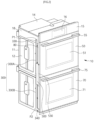
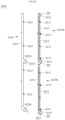
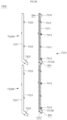
- a part of the wire harnesses W1, W2a, and W2b connected from the doors 50 and 70 to the equipment room S1 may be disposed along a wire guide 300.
- the wire guide 300 disposed on a side surface of the casing is illustrated.
- the wire guide 300 may include two wire guides 300A and 300B. The wire guide 300 will be described below.
- the wire harnesses W1, W2a and W2b may include a connection wire W1 and door wires W2a and W2b.
- the connection wire W1 may include upper wires Wlal, Wlbl, and W1c1 and lower wires W1a2, W1b2, and W1c2.
- the upper wires Wlal, Wlbl, and W1c1 may include a first door connection part Wlal, a first extension part Wlbl, and an equipment room connection part W1c1.
- the lower wires W1a2, W1b2, and W1c2 may include a second door connection part W1a2, a second extension part W1b2, and a wire connection part W1c2. It may be seen that the first door connection part Wlal, the first extension part Wlbl, and the equipment room connection part W1c1 divide one component connected to each other for convenience. It may be seen that the second door connection part W1a2, the second extension part W1b2, and the wire connection part W1c2 also divide one component connected to each other for convenience.
- the door wires W2a and W2b include a first door wire W2a disposed on the upper door 50 and a second door wire W2b disposed on the lower door 70.
- the first door wire W2a and the second door wire W2b may be configured separately from each other.
- the first wire door W2a may connect the second electronic component 100 disposed on the upper door 50 and the upper wires Wlal, Wlbl, and W1c1.
- the second wire door W2b may connect the second electronic component 100 disposed in the lower door 70 and the lower wires W1a2, W1b2, and W1c2.
- connection wire W1 may be integrated.
- connection wire W1 and the door wires W2a, W2b may be integrated.
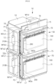
- the wire harnesses W1, W2a, W2b may be connected to each other through connectors. Looking at FIG. 5 , a total of four connection points may be seen from bottom to top. Each wire constituting the wire harness W1, W2a, and W2b may be coupled at connection points.
- the wires may be coupled by the connectors.
- the second door wire W2b connected to the lower door 70 and the lower wires W1a2, W1b2, and W1c2 may be connected.
- the lower wires W1a2, W1b2, and W1c2 and the upper wires Wlal, Wlbl, and W1c1 may be connected.
- the third connection point L3 the first door wire W2a connected to the upper door 70 and the upper wires Wlal, Wlbl, and W1c1 may be connected.
- the fourth connection point L4 the upper wires Wlal, Wlbl, and W1c1 and the component wire W1d may be connected.
- a rear cover 11, side cover 12, and upper cover 14 that constitute the cooking appliance may form the casing of the main body 10.
- a cavity (not shown) constituting the storage compartment may be provided inside the rear cover 11, the side cover 12, and the upper cover 14.
- the cavity may also be viewed as a type of inner casing.
- reference numeral 12a denotes a recess part provided in the center of the side cover 12. Based on the recess part 12, the side cover 12 may be divided into an upper part and a lower part.
- An upper panel 15 may be provided on the upper part of the cooking appliance.
- the upper panel 15 may be disposed on the front upper part of the cooking appliance.
- the upper panel 15 may be provided with a display part 16.
- the display part 16 may serve to operate a function of the cooking appliance and display a status of the cooking appliance.
- the display part 16 may be configured as a display capable of touch operation.
- the display part 16 may be omitted from the upper panel 15 and the display part may be placed on the doors 50 and 70.
- an equipment room S1 may be disposed at the rear of the upper panel 15.
- the equipment room S1 may be a space partitioned from the storage compartment.
- the equipment room S1 may be placed between the upper cover 14 and an upper casing 18.
- the upper casing 18 may be placed on the upper portion of the side cover 12.
- the upper casing 18 may be arranged around the side of the equipment room S1.
- the upper door 50 may be placed on the front of the casing.
- the lower door 70 may be placed on the front of the casing at a different height from the upper door 50.
- the upper door 50 and the lower door 70 may each be operated in a kind of pull-down method in which the upper end rotates up and down around the lower end.
- the upper door 50 and the lower door 70 may each be operated in a side swing manner.
- the front 51 of the upper door 50 may have a structure that allows an upper storage compartment 31 to be seen through.
- the front 51 of the upper door 50 has a panel structure made of glass, so that a user may observe the inside of the storage compartment through the upper door 50.
- the front 51 of the upper door 50 may be made of a dark material or coated with a separate film so that the storage compartment is not visible from the outside.
- Reference numeral 55 denotes a first handle for opening and closing the upper door 50.
- the lower door 70 may be placed below the upper door 50.
- the lower door 70 may be placed at the front lower part of the casing.
- the storage compartment may be seen through the front of the lower door 70. The user may observe the inside of the storage compartment through the front of the lower door 70.
- a transparent part may be provided at the center of the lower door 70.
- the transparent part is for viewing the storage compartment from the outside, and may be made of a transparent material.
- the transparent part may be viewed as a part of a front panel Ga constituting the front of the lower door 70.
- the transparent part may be provided at the center of the front panel Ga.
- the edge portion of the front panel Ga may be made of a material with high surface roughness, unlike the transparent part.
- a separate opaque film may be applied to the edge of the front panel Ga. In this case, the edge portion of the front panel Ga, excluding the transparent portion, may not be visible through the storage compartment.
- the edge of the front panel Ga outside of the transparent part may be covered by a door frame 72.
- the outside of the transparent part may mean an edge portion of the front panel Ga disposed around the edge of the transparent part.
- the lower door 70 may be made of a dark material or coated with a separate film so that the storage compartment is not visible from the outside.
- a transparent door panel may be omitted in the lower door 70, and an opaque metal or non-metal plate may form the front surface. Even in this case, the storage compartment may not be visible from the outside.
- a side plate 80 may be provided on the side surface of the casing.
- the side plate 80 may be disposed on the front side of the casing close to the side of the doors 50 and 70. As shown in FIG. 8 , the side plate 80 may be placed in the front of the side cover 12. Additionally, the side plate 80 may be disposed behind the doors 50 and 70.
- the side plate 80 may extend long in the height direction of the casing so as to be adjacent to both the upper door 50 and the lower door 70. Referring to FIG. 9 , the side plate 80 may be provided higher than the adjacent wire guide 300.
- a guide bracket 500 which will be described below, may be fixed to the side plate 80.
- the side plate 80 may have a flat structure made of metal.
- the side plate 80 may serve to align the left and right sides of the main body 10 so that they are not misaligned when the main body 10 is stored in the furniture 1. To this end, the side plate 80 may protrude from the side cover 12.
- the side plate 80 may protrude further from the side of the casing than the wire guide 300, or may form a continuous plane with the wire guide 300.
- the side plate 80 may be disposed closer to the doors 50 and 70 than the wire guide 300. In this way, when the main body 10 is stored in the furniture 1, the side plate 80 may cover the wire guide 300 so that the wire guide 300 is not visible from the front. As another example, the side plate 80 may be omitted. As another example, the side plate 80 may be integrally formed with the side cover 12 constituting the casing.
- the side plate 80 may be provided with a plate recess part 82.
- the plate recess part 82 may be formed by a portion of the side plate 80 being recessed toward the side surface of the casing.
- the plate recess part 82 may form a continuous wire path together with the wire guide 300. Referring to FIG. 14 in which the guide bracket 500 is removed, the plate recess part 82 of the side plate 80 is exposed to the outside. Wire harnesses W1, W2a, and W2b may be placed in the plate recess part 82.
- the plate recess part 82 may be covered by the guide bracket 500.
- the equipment room S1 may be provided on the upper part of the main body 10.
- the equipment room S1 may be placed below the upper cover 14.
- the equipment room S1 may be formed at a position corresponding to a lower portion of the upper cover 14, the rear side of the upper panel 15, and between the upper casing 18 disposed on both sides.
- the equipment room S1 may be disposed on the side, back, or bottom of the main body 10.
- the first electronic component 90 and a cooling fan 97 may be placed in the equipment room S1.
- the cooling fan 97 may serve to lower the temperature of the main body 10 by drawing in and circulating external air.
- a cooling duct which is a flow path for air flowing by the cooling fan 97, may be disposed in the equipment room S1.
- the first electronic component 90 may include a control part that controls the display unit 16 and the second electronic component 100.
- the first electronic component 90 may be composed of a substrate.
- a plurality of electrodes 92 may be disposed on the substrate.
- the display part 16 and a knob may be disposed in front of the substrate.
- a through hole 18a may be provided in the upper casing 18.
- the through hole 18a may be formed to pass through the upper casing 18.
- the through hole 18a may expose the equipment room S1 to the outside.
- a guide hole OH of the wire guide 300 may be connected to the through hole 18a.
- reference numeral 316 denotes a guide arm of the wire guide 300.
- the guide arm 316 may pass through the through hole 18a and may be inserted into the equipment room S1.
- the guide hole OH may be provided inside the guide arm 316.
- the second electronic component 100 and the door wire W2a and W2b may be disposed on the doors 50 and 70.
- the second electronic component 100 disposed on the two doors 50 and 70 may be configured identically to each other.
- different types of second electronic component 100 may be disposed on the two doors 50 and 70, respectively.
- a lighting device may be disposed on the upper door 50
- an image sensing device 170 for photographing an image may be disposed on the lower door 70.
- the second electronic component 100 is an image acquisition module as an example.
- the second electronic component 100 disposed in the lower door 70 will be described with reference to FIG. 6 .
- the reference numeral Is denotes an inward direction toward the main body 10
- Os denotes an outward direction away from the main body 10.
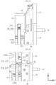
- a connector module 200 may be provided under the lower door 70.
- the connector module 200 may connect the second door wire W2b and the second door connection part W1a2 of the lower wires W1a2, W1b2, and W1c2.
- the connector module 200 may include a connector assembly C in which two connectors 270 and 290 are assembled. If necessary, an operator may separate the second door wire W2b from the second door connection part W1a2 of the lower wires W1a2, W1b2, and W1c2 from the connector module 200, and maintain/repair the second electronic component 100.
- the image acquisition module 100 as the second electronic component 100 is represented in a see-through state, but the image acquisition module 100 may be shielded by an edge part of the front panel Ga (see FIG. 6 ).
- the door connector 270 constituting the connector module 200 may be assembled with the counterpart connector 290.
- the door connector 270 may be connected to the second door wire W2b.
- the counterpart connector 290 may be connected to the second door connection part W1a2 of the lower wires W1a2, W1b2, and W1c2.
- the lower wires W1a2, W1b2, and W1c2 may be electrically connected to the second door wire W2b.
- the two connectors 270 and 290 may be omitted, and the connection wire W1 and the second door wire W2b may be directly connected to each other.
- the connection wire W1 and the second door wire W2b may be integrally formed.
- the connector module 200 may be disposed in a connector storage part CM.
- the connector storage part CM may be disposed in an installation area provided inside the lower door 70.
- the connector storage part CM may be viewed as an empty space that is a part of the installation area.
- the connector storage part CM may be a bracket formed integrally with the installation area or separately.
- the connector storage part CM may be disposed adjacent to a lower end portion of a side surface of the lower door 70.
- the operator may access the connector module 200 through the lower portion of the lower door 70.
- the connector module 200 may not be exposed to the outside normally. Also, since an inlet of the connector storage part CM is open to the lower end portion of the lower door 70, the operator may easily access the connector module 200.
- the connector storage part CM may be disposed adjacent to the upper end of the side surface of the lower door 70. Also, the inlet of the connector storage part CM may be open to the side surface of the lower door 70.
- a frame of the lower door 70 may be formed by the door frame 72.
- the door frame 72 may include a frame body 72a having an approximately rectangular frame shape.
- a through part 72b which is a kind of empty space, may be open at the center of the frame body 72a.
- the front panel Ga may be disposed at the through part 72b.
- Reference numeral 77a denotes a frame discharge port, and the frame discharge port 77a may be an outlet through which air having passed through a cooling passage formed in the lower door 70 is discharged to the outside.
- the second electronic component 100 may include a main unit 100A and a connection unit 100B.
- the main unit 100A may include an image sensing device 170.
- the connection unit 100B may create a path through which the second door wire W2b is guided to the main unit 100A.
- the first electronic component 90 may be transferred to the second electronic component 100 disposed in the lower door 70.
- the signal or power of the first electronic component 90 may be transferred in the order of component wire W1d - the fourth connection point L4 - the upper wires Wlal, Wlbl, W1c1 - the second connection point L2 - the lower wires W1a2, W1b2, W1c2 - the first connection point L1 - the connector module 200 - the second door wire W2b - the second electronic component 100.
- the first electronic component 90 may also be transferred to the second electronic component 100 disposed in the upper door 50. Specifically, the signal or power of the first electronic component 90 may be transferred in the order of component wire W1d - fourth connection point L4 - upper wires Wlal, Wlbl, W1c1 - third connection point L3 - connector module 200 - first door wire W2a - second electronic component 100.
- the second door connection part W1a2 may be disposed in the front-rear direction (X-axis direction).
- the second door connection part W1a2 may extend rearward from the counter connector 290 along the lower portion of the main body 10.
- the equipment room connection part W1c1 may extend in the direction of the equipment room S1 from the upper end of the first extension part Wlbl, and a part of the component wire W1d may extend in the left-right direction (Y-axis direction).
- the first extension part W1b1 and the second extension part W1b2 are continuously connected to each other for better understanding, but the first extension part W1b1 and the second extension part W1b2 may be connected to each other by a connector.
- connection wire W1 including the first extension part W1b1 and the second extension part W1b2 may extend in the height direction (Z-axis direction) of the main body 10.
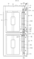
- the first extension part W1b1 and the second extension part W1b2 may be disposed on a side surface of the casing. Since the connection wire W1 including the first extension part W1b1 and the second extension part W1b2 is disposed on a side surface of the casing, the overall length may be reduced as compared with that of the connection wire W1 connected to the first electronic component 90 via the rear side of the main body 10.
- the dotted line illustrates a path when the connection wire W1 rotates around the rear surface of the main body 10 and enters the equipment room S1.
- the first extension part W1b1 and the second extension part W1b2 are disposed closer to the front surface of the main body 10, that is, the doors 50 and 70, than the rear surface of the main body 10, and thus, there is no need to extend to the rear surface of the main body 10. Accordingly, the entire length of the connection wire W1 is shortened, and noise mixed with the signal may be reduced.
- first extension part W1b1 and the second extension part W1b2 are disposed on the side surface of the casing, they may be more directly affected by heat diffused from the surface of the casing as compared with the second door connection part W1a2 or the equipment room connection part W1c1. Therefore, it is necessary to block the connection wire W1 including the first extension part W1b1 and the second extension part W1b2 from the surface of the casing.
- the blocking between the connection wire W1 and the surface of the casing may be performed by the wire guide 300.
- the wire guide 300 may block laterally between the side cover 12 and the connection wire W1.
- the wire guide 300 may block a flow of heat transferred to the connection wire W1 on the surface of the side cover 12.
- the wire guide 300 may surround the first extension part W1b1 and the second extension part W1b2 to protect the first extension part W1b1 and the second extension part W1b2 from a high temperature environment.
- blocking laterally means that the surface of the casing and the connection wire W1 do not face each other directly.
- radiant heat generated from the surface of the casing may not be directly transferred to the connection wire W1.
- the connection wire W1 may be disposed on the surface of the cavity (not shown) disposed inside the casing so that radiant heat generated from the surface of the cavity is not directly transferred to the connection wire W1.
- the wire guide 300 may be disposed on the surface of the side cover 12.
- the wire guide 300 may surround the connection wire W1 so that the connection wire W1 is not exposed to the outside. More specifically, the wire guide 300 may surround the first extension part W1b1 and the second extension part W1b2 of the connection wire W1.
- Guide covers 320A and 320B may cover the first extension part W1b1 and the second extension part W1b2 while the first extension part W1b1 and the second extension part W1b2 are stored in the guide channel 312 of the wire guide 300.
- the first extension part W1b1 and the second extension part W1b2 may be stored in guide bases 310A and 310B constituting the wire guide 300.
- the wire guide 300 may be disposed between a first point P1 entering the inside of the electronic component S1 and a second point P2 entering the doors 50 and 70.
- first point P1 entering the inside of the electronic component S1
- second point P2 entering the doors 50 and 70.
- both ends of the connection wire W1 may be naturally guided to the lower door 70 and the electronic component S1, respectively.
- the second point P2 refers to a space between a lower portion of the lower door 70 and a lower portion close to a bottom of the main body 10.
- the first point P1 refers to an upper portion of the main body 10 close to the upper casing 18.
- the wire guide 300 may be disposed along a straight path between the first point P1 and the second point P2.
- the first point P1 and the second point P2 are spaced apart from each other in the height direction (Z-axis direction) of the main body 10. Accordingly, the wire guide 300 may be provided in the height direction of the main body 10.
- the first extension part W1b1 and the second extension part W1b2 of the connection wire W1 may also be disposed along a straight path between the first point P1 and the second point P2 along the wire guide 300.
- the straight path may be the shortest distance connecting the first point P1 and the second point P2.
- the wire guide 300 may be disposed adjacent to the side plate 80.
- the wire guide 300 may be disposed at a position recessed rearward from the doors 50 and 70 than the side plate 80. Accordingly, when viewed from the front of the main body 10, the wire guide 300 may be covered by the side plate 80.
- the wire guide 300 may be disposed closer to the front than the rear of the main body 10. That is, the wire guide 300 may be disposed closer to the doors 50 and 70 than the rear cover 11. In this case, compared to the wire guide 300 being disposed close to the rear cover 11, the length of the wire guide 300 and the connection wire W1 disposed on the wire guide 300 may be relatively shortened. The wire guide 300 is disposed closer to the doors 50 and 70 than the side center of the casing.
- the wire guide 300 may include a plurality of wire guides 300A and 300B. Referring to FIG. 8 , the first wire guide 300A and the second wire guide 300B arranged at a different height from the first wire guide 300A are provided.
- the second wire guide 300B may form a continuous guide path with the first wire guide 300A, and the connection wire W1 may be arranged along the guide path.
- the first wire guide 300A and the second wire guide 300B may have similar shapes. In this way, the plurality of wire guides 300A, 300B may also insulate wire W1, W2 provided in a high home appliance.
- the first wire guide 300A may be disposed adjacent to the upper door 50.
- the second wire guide 300B may be disposed adjacent to the lower door 70.
- One end of the first wire guide 300A and the second wire guide 300B may be disposed in contact with each other.
- reference numeral AP indicates a contact portion where the first wire guide 300A and the second wire guide 300B are in close contact with each other.
- the first wire guide 300A and the second wire guide 300B may be arranged to be spaced apart from each other.
- a first guide part 330 may be provided at the upper end of the first wire guide 300A.
- the first guide part 330 may be provided with a guide arm 316.
- the guide arm 316 may be inserted into the through hole 18a open in the upper casing 18.
- the equipment room connection part W1c1 constituting the upper wires Wlal, Wlbl, and W1c1 are guided by the guide arm 316 and may enter the inside of the through hole 18a.
- the equipment room connection part W1c1 may be connected to the component wire W1d at the fourth connection point L4 (see FIG. 5 ).
- a second guide part 340 may be provided at the lower end of the first wire guide 300A.
- the second guide part 340 may extend forward. More precisely, the second guide part 340 of the first wire guide 300A may extend in the direction of the upper door 50. In this way, the first guide part 330 and the second guide part 340 may extend in different directions.
- the first door connection part W1a1 of the upper wires Wlal, Wlbl, and W1c1 are guided to the lower part of the upper door 50 along the second guide part 340 extending in the direction of the upper door 50.
- the plate recess part 82 of the side plate 80 may form a continuous wire path together with the second guide part 340.
- the plate recess portion 82 may be covered by the second guide part 340.
- the first door connection part W1a1 may be stored inside the first wire guide 300A through plate recess part 82.
- the guide covers 320A and 320B may protrude further than the guide bases 310A and 310B constituting the second guide part 340. Accordingly, the guide bases 310A and 310B do not overlap the plate recess part 82, and the guide covers 320A and 320B may cover the upper part of the plate recess part 82. This structure may prevent the side of the casing from becoming thick.
- the second wire guide 300B may be disposed below the first wire guide 300A.
- the second guide part 340 of the first wire guide 300A may be arranged continuously with the first guide part 330 of the second wire guide 300B.
- the upper wires Wlal, W1b1 and W1c1 and the lower wires W1a2, W1b2 and W1c2 may be sequentially arranged along the second guide part 340 of the first wire guide 300A and the first guide part 330 of the second wire guide 300B.
- FIG. 12 a state in which the guide covers 320A and 320B of the wire guide 300 are removed is illustrated.
- the guide channel 312 formed in the first wire guide 300A and the guide channel 312 provided in the second wire guide 300B can be open, respectively.
- the two guide channels 312 may be connected to each other to form one guide path extending in the vertical direction.
- the guide arm 316 of the first wire guide 300A may be provided around the guide hole OH.
- the guide hole OH may be formed through the guide bases 310A, 310B.
- the guide hole OH may be connected to the through hole 18a of the side plate 80.
- the equipment room connection part W1c1 of the upper wires Wlal, Wlbl, and W1c1 may enter the inside of the equipment room S1 through the guide hole OH and the through hole 18a.
- FIG. 14 illustrates the part where the lower part of the first wire guide 300A and the upper part of the second wire guide 300B meet, that is, the central part of the side cover 12.
- a first channel hole CH1 may be open downward at the lower part of the first wire guide 300A.
- a second channel hole CH2 connected to the first channel hole CH1 in the vertical direction (Z-axis direction) may be open upward.
- the wire harnesses W1, W2a, and W2b may be sequentially stored through the first channel hole CH1 and the second channel hole CH2 connected to each other.
- FIG, 14 illustrates the plate recess part 82 of the side plate 80 forming a continuous wire path together with the second guide part 340 of the first wire guide 300A.
- the plate recess part 82 and the second guide part 340 may be connected to each other in the left and right direction (X-axis direction) based on the drawing.
- the first door connection part W1a1 constituting the upper wires Wlal, Wlbl, W1c1 may be stored inside the first wire guide 300A via the plate recess part 82.
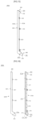
- the first wire guide 300A is shown in FIGS. 15 and 16 .
- the first wire guide 300A may include a first guide part 330 extending toward the equipment room S1 where the first electronic component 90 is disposed and a second guide part 340 provided on the other side of the first guide part 330.
- the second guide part 340 may extend toward the upper door 50. In this way, the first guide part 330 and the second guide part 340 may extend in different directions.
- the first wire guide 300A may include a guide base 310A and a guide cover 320A.
- the guide base 310A may be disposed on a side of the casing, that is, on the surface of the side cover 12.
- the guide base 310A may be provided with a guide channel 312.
- the guide channel 312 may be provided between the bottom part of the guide base 310A and a pair of fence parts 311 provided on both sides of the bottom part.
- the wire harness W1, W2a, W2b may be stored in the guide channel 312. More precisely, the upper wires Wlal, Wlbl, W1c1 constituting the wire harnesses W1, W2a, W2b may be stored in the guide channel 312.
- the guide channel 312 may be open in a direction opposite to the surface direction of the side cover 12.
- the open portion of the guide channel 312 may be shielded by the guide cover 320A.
- the operator may assemble the guide cover 320A to the guide base 310A after storing the wire harnesses W1, W2a, and W2b in the guide channel 312.
- the fence part 311 may be provided with a plurality of base fastening pieces 313.
- the base fastening pieces 313 may protrude from the fence part311 and come into close contact with the side cover 12.
- the base fastening pieces 313 may be parts to which fasteners such as screws (not shown) are fastened. Some of the base fastening pieces 313 may be fastened with fasteners while overlapping with cover fastening pieces 323 provided on the guide cover 320A.
- a guide hole OH and a door connection hole DH may be open at both ends of the guide channel 312, respectively.
- the guide hole OH may be open toward the equipment room S1.
- the guide hole OH may be open between the pair of guide arms 316.
- the guide hole OH may be connected to a channel end 312a formed at the upper end of the guide channel 312.
- the guide arm 316 may pass through the through hole 18a and connect the guide hole OH and the through hole 18a.
- the guide base 310A may be provided with a base extension part 315 extending in the direction of the doors 50 and 70.
- the guide channel 312 may be connected to the base extension part 315.
- a door connection hole DH open toward a lower portion of the door 50 may be provided at an end portion of the base extension part 315.
- the base extension part 315 may form the second guide part 340 together with a cover extension part 325, which will be described later.
- the door connection hole DH may be open toward the lower part of the doors 50 and 70.
- the door connection hole DH may be open in a direction different from the guide hole OH. If the guide hole OH is open in the left and right width directions (Y-axis direction in FIG. 1 ) of the main body 10, the door connection hole DH may be open in the front-back direction (X Y-axis direction in FIG. 1 ) of the main body 10.
- a first channel hole CH1 may be open in the lower part of the guide base 310A.
- the first channel hole CH1 may be open in the longitudinal direction of the guide base 310A, that is, in the height direction of the main body (Z-axis direction in FIG. 1 ).
- the guide hole OH, the door connection hole DH, and the first channel hole CH1 may each be open in different directions.
- the first channel hole CH1 may be connected to a second channel hole CH2 of the second wire guide 300B.
- Reference numeral 319 denotes a base groove recessed in the fence part 311.
- the base grooves 319 may be provided at regular intervals along the longitudinal direction of the fence part 311.
- the base groove 319 may allow the guide base 310A to bend more easily in the direction of the side cover 12. If the flexibility of the guide base 310A is increased by the base groove 319, the first wire guide 300A may be more easily mounted on the side cover 12.
- the guide cover 320A may have a similar shape to the guide base 310A.
- the guide cover 320A may be coupled to the guide base 310A to form the exterior of the first wire guide 300A.
- a cover body 321 of the guide cover 320A may have a flat structure that covers the guide channel 312.
- the cover body 321 may be viewed as defining the guide channel 312 together with the guide base 310A.
- the cover body 321 may be provided with a plurality of cover fastening pieces 323.
- the cover fastening pieces 323 may be fastened with a fastener while overlapping some of the base fastening pieces 313.
- the base fastening pieces 313 and the cover fastening pieces 323 may be omitted, and the fastener may pass through the bottom of the guide base 310A.
- the first wire guide 300A may be attached to the surface of the side cover 12 with adhesive.
- a cover extension part 325 may be provided at the lower part of the guide cover 320A.
- the cover extension part 325 may extend from the guide cover 320A toward the upper door 50 and cover the base extension part 315.
- the cover extension part 325 may form the door connection hole DH together with the base extension part 315.
- the cover extension part 325 may extend longer than the base extension part 315. More precisely, as shown in FIG. 14 , the guide base 310A does not overlap with the plate recess part 82, and as shown in FIG. 10 , only the guide cover 320A may cover the upper portion of the plate recess part 82. This structure may prevent the side of the casing from becoming thick.
- Reference numeral 325a denotes a cover fastening hole for fastening the guide cover 320A to the side plate 80.
- a cover hole 328 may be open at the upper end of the guide cover 320A.
- the cover hole 328 allows the upper part of the first wire guide 300A to be open upward.
- the cover hole 328 may create the second channel hole CH2.
- the first wire guide 300A does not need the second channel hole CH2, but when the cover hole 328 is provided, the guide cover 320A of the first wire guide 300A and guide cover 320A of the second wire guide 300B may be shared.
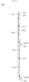
- the second wire guide 300B will be described with reference to FIGS. 17 and 18 . Since the structure of the second wire guide 300B is similar to that of the first wire guide 300A, the parts that are different from the first wire guide 300A will be mainly described, and the remaining parts will be given the same reference numerals and detailed descriptions will be omitted.
- the second wire guide 300B may include a first guide part 330 extending toward the equipment room S1 where the first electronic component 90 is disposed and a second guide part 340 provided on the other side of the first guide part 330.
- the first guide part 330 may be viewed as facing the second guide part 340 of the first wire guide 300A.
- the second guide part 340 of the second wire guide 300B may extend toward the lower door 70. In this way, the first guide part 330 and the second guide part 340 may extend in different directions.
- the guide arm 316 may be omitted from the guide base 310B constituting the second wire guide 300B.
- the base hole 318 for forming the second channel hole CH2 may be open at the upper end of the guide base 310B.
- the base hole 318 may cooperate with the cover hole 328 of the guide cover 320B to create the second channel hole CH2.
- the second channel hole CH2 may be connected to the first channel hole CH1 of the first wire guide 300A.
- the wire harnesses W1, W2a, W2b may be sequentially arranged through the first channel hole CH1 and the second channel hole CH2.
- the guide bracket 500 may be disposed on the surface of the casing. Referring to FIGS. 7 and 8 , the guide bracket 500 may be fixed to the surface of the side cover 12. The guide bracket 500 may extend rearward, that is, toward the rear cover 11, from a position adjacent to the doors 50 and 70. A portion of the guide bracket 500 may cover the wire guide 300.
- the guide bracket 500 may align the main body 10 so that the insertion posture of the main body 10 is not distorted when the main body 10 is stored in the furniture 1.
- the guide brackets 500 may be provided on both sides of the main body 10, respectively. Since the guide bracket 500 covers the wire guide 300, it is possible to prevent the wire guide 300 from being damaged by colliding with the furniture 1.
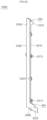
- FIG. 19 illustrates the structure of the guide bracket 500.
- the guide bracket 500 may have a thin plate structure.
- the guide bracket 500 may be made by bending a metal material several times.
- the guide bracket 500 may have a structure that protrudes from the side plate 80 through a bent structure.
- the guide bracket 500 may include a bracket body 510 that covers the wire guide 300, and a mounting body 530 extending from the bracket body 510 toward the door.
- the mounting body 530 is a part fixed to the casing.
- the mounting body 530 may be fixed to the side plate 80.
- Reference numeral 512 denotes a fastener hole for fixing the bracket body 510 to the wire guide 300.
- the mounting body 530 may protrude further from the side of the casing than the bracket body 510. In this way, the mounting body 530 protrudes from the side of the casing and may serve as a kind of spacer to fill the gap between the inner surface of the furniture 1 and the side cover 12.
- the mounting body 530 may have an approximately U-shaped cross section.
- the mounting body 530 may include: a first body 531 connected to the bracket body 510 in a vertical direction; a second body 533 perpendicular to the first body 531 and parallel to the bracket body 510; and a third body 535 perpendicular to the second body 533 and parallel to the first body 531.
- the first body 531, second body 533, and third body 535 may form a " ⁇ " shape, and have a predetermined thickness H.
- the mounting body 530 may protrude from the side cover 12 by this thickness H.
- Reference numeral 536 denotes a space formed inside the mounting body 530 bent in the " ⁇ " shape.
- the doors 50, 70 protrude further in the left and right width directions (Y-axis direction in FIG. 1 ) than the side covers 12, the doors 50, 70 occupy the entire front of the furniture 1, and may cover a gap between the furniture 1 and the side cover 12 to enhance aesthetics.
- the side cover 12 and the inner surface of the furniture 1 are spaced apart, and when the main body 10 may be misaligned inside the furniture 1.
- the mounting body 530 has a predetermined thickness H, so it may fill the gap between the side cover 12 and the inner surface of the furniture 1. Accordingly, the main body 10 may be aligned to face forward inside the furniture 1.
- the mounting body 530 may be provided with a plurality of mounting holes 534.
- a fastener such as a screw that passes through the mounting holes 534 may assemble the mounting body 530 to the side plate 80.
- Reference numeral 537 denotes an avoidance part to avoid interference with the doors 50 and 70 during the rotation process of the doors 50 and 70.
- the guide bracket 500 may simultaneously cover the lower part of the first wire guide 300A and the upper part of the second wire guide 300B. Through this, the guide bracket 500 may protect both the first wire guide 300A and the second wire guide 300B.
- a home appliance may be a single-stage cooking appliance.
- the single-stage cooking appliance has a relatively low height compared to the previous embodiment.
- the wire guide 1300 may be composed of one piece. The lower end of the wire guide 1300 extends to the lower part of the casing adjacent to the lower frame 20, and the other end of the wire guide 1300 may extend to the equipment room S1.
- Reference numeral 17 denotes a knob provided separately from the display part 16.
- the wire guide 2300 may include a guide base 2310 and a guide cover 2320.
- the guide base 2310 and the guide cover 2320 may be combined to form the single wire guide 2300.
- the wire guide 2300 may be provided with a first guide part 2330 and second guide parts 2340A and 2340B.
- the first guide part 2330 may be provided with a guide arm 2316 connected to the equipment room S1 and a guide hole OH open inside the guide arm 2316.
- the first guide part 2330 may be provided at one end of the wire guide 2300.
- the wire guide 2300 may be provided with a plurality of second guide parts 2340A and 2340B.
- the second guide parts 2340A and 2340B may extend from the wire guide 2300 toward the plurality of doors 50 and 70, respectively. As shown in FIG. 21 , the second guide parts 2340A and 2340B may have different heights and protrude in the same direction.
- the connection wire W1 extending along the second guide parts 2340A and 2340B may be connected to the second electronic components 100 of the upper door 50 and lower door 70, respectively.
- FIG. 22 illustrates a wire guide 3300 constituting a fourth embodiment of the home appliance according to the present invention.
- the wire guide 3300 may be configured to have a relatively low height, unlike the previous embodiments.
- the wire guide 3300 is disposed on the side cover 12 and may accommodate a part of the wire harnesses W1, W2a, and W2b.
- the wire guide 3300 may be adjacent to the upper door 50 or adjacent to the lower door 70.
- FIG. 23 illustrates a wire guide 4300 constituting a fifth embodiment of the home appliance according to the present invention.
- the same parts as in the previous embodiment will be assigned the same reference numeral 4000 series and the description will be omitted.
- the wire guide 4300 may be composed of only a guide base 4310 without a separate guide cover.
- a guide channel 4312 may be formed inside the guide base 4310.
- a partition rib 4312a may protrude from a bottom part constituting the guide channel 4312.
- the partition rib 4312a may be disposed between a pair of fence parts 4311.
- the partition rib 4312a may be erected at the bottom part to partition the guide channel 4312.
- the partition ribs 4312a may support the surfaces of the wire harnesses W1, W2a, and W2b to prevent the wire harnesses W1, W2a, and W2b from moving inside the guide channel 4312.
- the partition rib 4312a may also be provided on the guide base of the previous embodiments.
- FIG. 24 illustrates a wire guide 5300 constituting a sixth embodiment of the home appliance according to the present invention.
- the same parts as in the previous embodiment will be assigned the same reference numerals in the 5000 series and the description will be omitted.
- the wire guide 5300 may only extend in one direction. Based on the drawing, the wire guide 5300 extends in the vertical direction.
- a guide hole OH and a door connection hole DH may be open at both ends of the guide channel 5312 provided in the wire guide 5300, respectively.
- the guide hole OH and the door connection hole DH may be open in different directions.
- the door connection hole DH may be made by omitting a part of the fence part 5311 constituting the wire guide 5300. That is, the wire guide 5300 does not have a second guide part extending toward the doors 50 and 70, and the door connection hole DH is provided directly at one end of the wire guide 5300.
- the wire guide 6300 may include two guide bases 6310A and 6310B and a single guide cover 6320.
- the guide cover 6320 may be coupled simultaneously with the two guide bases 6310A and 6310B. That is, the one guide cover 6320 may shield both guide channels 6312 provided on the two guide bases 6310A and 6310B, respectively.
- the guide cover 6320 may be provided with two cover extension parts 6325A and 6325B.
- the two cover extension parts 6325A and 6325B may be provided at different heights from each other.
- the two cover extension parts 6325A and 6325B may overlap a base extension part 6315 provided in the first guide base 6310A and the base extension part 6315 provided in the second guide base 6310B, respectively.
- the two cover extension parts 6325A and 6325B may cover and shield extension channels 6317 provided in each of the two base extension parts 6315.
- the wire guide 7300 may include one guide base 7310 and two guide covers 7320A and 7320B. Each of the guide covers 7320A and 7320B may be coupled to the one guide base 7310. That is, the two guide covers 7320A and 7320B may shield all of a plurality of guide channels 7312 provided in the one guide base 7310.
- the one guide base 7310 may be provided with two base extension parts 7315A and 7315B.
- the two base extension portions 7315A and 7315B may be provided at different heights from each other.
- the two base extension parts 7315A and 7315B may overlap cover extension parts 7325 provided on the two guide covers 7320A and 7320B, respectively.
- the two cover extension parts 7325 may cover and shield extension channels 7317A and 7317B provided in each of the two base extension parts 7315A and 7315B.
Landscapes
- Engineering & Computer Science (AREA)
- Mechanical Engineering (AREA)
- Chemical & Material Sciences (AREA)
- Combustion & Propulsion (AREA)
- General Engineering & Computer Science (AREA)
- Physics & Mathematics (AREA)
- Thermal Sciences (AREA)
- Insertion, Bundling And Securing Of Wires For Electric Apparatuses (AREA)
Abstract
The present invention is related to a home appliance. The home appliance of the present invention may include a casing having a storage compartment therein. A door may be disposed in front of the storage compartment to open and close the storage compartment. A first electronic component may be disposed outside the casing. A second electronic component may be disposed at the door. A wire may electrically connect the first electronic component and the second electronic component. A wire guide may be disposed in the casing. In this case, a guide channel in which the wire is stored may be formed inside the wire guide. This helps to prevent the direct transfer of heat/cold air from the home appliance to the wire.
Description
- The present invention relates to a home appliance.
- Commonly used home appliances, such as cooking appliances, refrigerators, and garment care devices, have a door that provides access to an internal space for storing items. These appliances typically consist of a cavity exterior with an interior compartment designed for storing objects, along with a door for opening and closing this compartment.
- Recently, various electronic components are installed on a door of a home appliance. For example, a touch sensor device, a display device, a lighting device, communication device, etc. may be installed on the door. These electronic components may be operated by being supplied with power from a main body of the home appliance.
- The electronic components may be electrically connected to a main control part provided in the home appliance body through a wire. The wire may be arranged along the inside of a main body of the home appliance to connect between the electronic components of the door and the main control part. Both ends of the wire disposed inside the main body may be connected to the electronic components of the door and the main control part, respectively.
- However, the wire provided in an electric home appliance with a very high internal temperature, such as a cooking appliance equipped with a heating device, may be heated higher than an allowable temperature. In particular, the wire disposed inside a main body of the home appliance is close to the heating device, so there is a risk that the wire is heated and damaged more easily. In this casing, wires used to connect communication devices or imaging devices are more vulnerable to high-temperature environments because it is difficult to apply high heat-resistant coating due to the nature of the product.
- In addition, if the wire is disposed inside the main body of the home appliance, there is a problem of poor workability for separating/assembling the wire. When it is necessary to separate/assemble the wire for maintenance of the home appliance, a worker must access the inside of the narrow body, which reduces workability.
- To solve this, the wire may be provided along the outer edge of the cavity. For example, the wire may be provided along the cavity surface of the home appliance. In this casing, the temperature of the wire may be relatively lowered compared to when the wire is disposed inside the main body of the home appliance, but since the cavity of the home appliance is also made of metal, there is still a problem that heat from the heating device is transmitted to the wire.
- Additionally, the wire may be arranged around the outer edge of the cavity so as not to be adjacent to the cavity of the home appliance main body. For example, the wire may extend from a lower portion of the door along the bottom of the home appliance to the rear of the home appliance. The wire extending to the rear of the home appliance moves upward along the rear of the home appliance and may be connected to the main control part.
- However, if the wire is arranged around the outer edge of the home appliance like this, not only does the length of the wire increase, increasing manufacturing costs, but there is also the problem of increased noise in the signal. In particular, in electronic components, communication devices and imaging devices are sensitive to noise mixed with signals, leading to performance degradation as the length of the wire increases.
- Meanwhile, recently, built-in home appliances that are stored inside furniture are also being used. However, in the process of storing a built-in home appliance inside furniture, there is a problem in that the wires exposed to the outside of the home appliance get caught on the surface of the furniture and are damaged or removed.
- The invention is specified by the independent claim. Preferred embodiments are defined by the dependent claims. The present invention has been made in an effort to solve various problems in the prior art, with the objective of providing a home appliance that shortens a wire installation path connecting a main body and a door while also insulating the wire from the heat/cold air of the home appliance transmitted to the wire.
- Another object of the present invention is to prevent wires from being damaged during installing the home appliance on furniture.
- A further object of the present invention is to arrange the wire along a certain installation path inside the home appliance.
- A further object of the present invention is to minimize wire exposure by arranging the wire slightly toward the rear, away from the front of the home appliance.
- According to the features of the present invention for achieving the above purposes, a home appliance of the present invention may include a casing having a storage compartment therein. A door may be disposed in front of the storage compartment to open and close the storage compartment. A first electronic component may be disposed outside the casing. A second electronic component may be disposed at the door. A wire may electrically connect the first electronic component and the second electronic component. A wire guide may be disposed in the casing. In this case, a guide channel in which the wire is stored may be formed inside the wire guide. This helps to prevent the direct transfer of heat/cold air from the home appliance to the wire.
- The wire guide may be disposed on a side surface of the casing in the height direction of the casing.
- The wire guide may be disposed closer to the door than the center of the side surface of the casing.
- An equipment room in which the first electronic component is placed may be provided at an upper portion of the casing.
- The wire guide may be disposed between a first point entering the interior of the equipment room and a second point entering the door.
- The equipment room in which the first electronic component is placed may be provided at the upper portion of the casing. One end of the guide channel may be open toward the equipment room. The other end of the guide channel may be open toward the lower part of the door.
- A through hole may be open in the upper portion of the casing defining the equipment room. The other end of the wire guide may be provided with a guide hole connected to the through hole.
- A guide arm inserted into the through hole protrudes from the other end of the wire guide, and the guide arm may protrude from an edge of the guide hole.
- The wire guide may include a guide base disposed on a side surface of the casing, and a guide cover coupled to the guide base and defining the guide channel together with the guide base.
- The guide base may include a bottom part on which the wire is seated, and a pair of fence parts provided on both sides of the bottom part.
- A partition rib may protrude from the bottom part. The partition rib may be disposed between the pair of fence parts.
- The wire guide may include a first guide part extending toward the equipment room where the first electronic component is disposed, and a second guide part provided on the other side of the first guide part and extending toward the door.
- The first guide part and the second guide part may extend in different directions.
- A guide hole that opens toward the equipment room may be open in the first guide part. A door connection hole that opens toward a lower part of the door may be open in the second guide part.
- The wire guide may include a first wire guide and a second wire guide arranged at a different height from the first wire guide. The first wire guide and the second wire guide may form a continuous guide path.
- A first channel hole and a second channel hole connected to each other may be open at the lower end of the first wire guide and the upper end of the second wire guide facing the lower end of the first wire guide.
- The first wire guide may be provided with a guide hole open toward the equipment room and a door connection hole open toward the lower part of the door. The guide hole, the door connection hole, and the first channel hole may be open in different directions.
- A side plate may be provided on the side surface of the casing. The side plate may be disposed closer to the door than the wire guide. The side plate may protrude more from the side surface of the casing than the wire guide or may form a continuous plane with the wire guide.
- The side plate may be provided with a plate recess part that is recessed toward the side surface of the casing. The plate recess part may form a continuous wire path together with the wire guide.
- The casing may be provided with a guide bracket. The guide bracket may cover one end of the wire guide.
- The guide bracket may cover one end of the wire guide that is open toward the door.
- The guide bracket may include a bracket body that covers the wire guide
- The guide bracket may include a mounting body that extends from the bracket body toward the door and is fixed to the casing. The mounting body may protrude more from the side surface of the casing than the bracket body.
- The casing may be equipped with a guide bracket. The guide bracket may cover a portion where the first wire guide and the second wire guide are connected.
- The home appliance according to the present invention as described above has the following effects.
- In the present invention, an electronic component disposed at a door may be connected to a main body of the home appliance through a wire. A wire guide is disposed between a casing and the wire to block each other. Accordingly, heat/cold air of the home appliance directly transmitted to the wire may be blocked. The insulation function by the wire guide may increase the durability of the wire and the operational reliability of the electronic component.
- In the present invention, the wire guide is disposed on a side surface of the home appliance, and the wire may extend from the side surface of the home appliance to the height direction of the home appliance along the wire guide. In this case, the wire does not need to extend from the front surface (door) of the home appliance to the rear surface of the home appliance, and thus the entire path of the wire may be shortened. The entire path of the shortened wire may reduce noise of a signal transmitted through the wire and improve the quality of the home appliance.
- In addition, in the present invention, the wire guide may form a path in which the wire extends. Since the wires may be arranged in a certain path along the wire guide, there is an effect of increasing the convenience of installing the wires. In addition, since the wires have a consistent path, interference with peripheral components may be prevented.
- In particular, in the present invention, the wire guide combines a guide base and a guide cover to create a guide channel, and the wire may be stored in the guide channel. As a result, the influence of surrounding temperature and humidity on the wire is reduced, and foreign substances may be blocked, thereby improving the durability of the wire.
- In addition, in the present invention, since the wire may be disposed on the side surface of the casing, compared to installing the wire under the casing or inside a frame, the operation of mounting/removing the wire may be easily performed. In particular, when a guide cover is removed, the wire may be exposed, providing the advantage of easy maintenance.
- In addition, connectors coupled to the wire may be assembled or separated from each other at a lower portion of the door located in the front of the home appliance, thereby improving accessibility to the connectors. Accordingly, the process of assembly and disassembly of the connector may be improved.
- In addition, in the present invention, the wire may exit from the lower portion of the door and be inserted into an equipment room provided in an upper portion of the home appliance. In this case, since the wire extends in the vertical direction along the wire guide disposed on the side surface of the casing, the wire may not be exposed to the outside. This helps maintain the aesthetics of the home appliance by preventing the wire from being exposed.
- Additionally, in the present invention, the wire guide may be partially covered by a guide bracket provided on the side surface of the casing. The metal guide bracket protects the wire guide during the process of storing the home appliance inside furniture, etc., and may prevent the wire guide and the built-in wire from being damaged.
- In this case, the guide bracket may protrude further from the side surface of the casing than the wire guide. The protruding guide bracket may prevent the wire guide from colliding with the surrounding area during the process of storing the home appliance. Additionally, the guide bracket may facilitate storing the home appliance by aligning the left and right sides of the home appliance during the process of storing the home appliance. Additionally, the guide bracket may act as a kind of spacer to maintain a certain distance between the furniture mounting space and the home appliance.
- Also, in the present invention, a plurality of wire guides are connected to each other, and the connected wire guides may form a continuous guide path. As such, the plurality of wire guides may insulate the wire provided in a home appliance having a high height. Therefore, the present invention may have compatibility applicable to home appliances of various sizes.
- Additionally, in the present invention, a side plate may be provided on the side surface of the casing. The side plate is provided with a plate recess part, so that a continuous guide path leading to the wire guide may be formed. Accordingly, the wire does not protrude from the side surface of the casing, and the storage capacity of the wire may be improved.
- Additionally, the wire guide of the present invention may be provided with partition ribs that partition the guide channel. The partition rib allows the wire to be aligned in a certain direction inside the guide channel. Therefore, workability of the wire storage may be improved, and the operational reliability may also be improved because the wire does not shake inside the wire guide.
-
-
FIG. 1 is a perspective view illustrating a state in which a first embodiment of a home appliance according to the present invention is stored in furniture. -
FIG. 2 is a perspective view illustrating the first embodiment of the present invention. -
FIG. 3 is a perspective view illustrating a state in which a guide bracket is separated according to the first embodiment of the present invention. -
FIG. 4 is a perspective view illustrating a state in which a wire guide is separated according to the embodiment of the present invention. -
FIG. 5 is a perspective view illustrating a wire cover constituting the wire guide is removed from the first embodiment of the present invention illustrated inFIG. 3 . -
FIG. 6 is a perspective view illustrating configurations of a door and a wire constituting the first embodiment of the home appliance according to the present invention. -
FIG. 7 is a perspective view illustrating an upper structure in the first embodiment of the present invention illustrated inFIG. 2 . -
FIG. 8 is a side view illustrating a side structure of the first embodiment of the present invention illustrated inFIG. 2 . -
FIG. 9 is an enlarged perspective view of the side upper structure of the first embodiment of the present invention illustrated inFIG. 3 . -
FIG. 10 is a perspective view illustrating a structure of an equipment room according to the first embodiment of the present invention. -
FIG. 11 is an enlarged perspective view of the side center structure of the first embodiment of the present invention illustrated inFIG. 3 . -
FIG. 12 is a side view illustrating the side structure in a state in which a guide cover and a guide bracket are removed in the first embodiment of the home appliance according to the present invention. -
FIG. 13 is an enlarged side view of the upper structure ofFIG. 12 . -
FIG. 14 is an enlarged side view of the central structure ofFIG. 12 . -
FIG. 15 is a perspective view illustrating the structure of a first wire guide constituting the first embodiment of the present invention. -
FIG. 16 is an exploded perspective view of the structure of the first wire guide constituting the first embodiment of the present invention. -
FIG. 17 is a perspective view illustrating the structure of a second wire guide constituting the first embodiment of the present invention. -
FIG. 18 is an exploded perspective view of the structure of the second wire guide constituting the first embodiment of the present invention. -
FIG. 19 is a perspective view illustrating the structure of a guide bracket constituting the first embodiment of the present invention. -
FIG. 20 is a perspective view illustrating a second embodiment of a home appliance according to the present invention. -
FIG. 21 is a perspective view illustrating the wire guide constituting a third embodiment of the home appliance according to the present invention. -
FIG. 22 is a perspective view illustrating the wire guide constituting a fourth embodiment of the home appliance according to the present invention. -
FIG. 23 is a perspective view illustrating the wire guide constituting a fifth embodiment of the home appliance according to the present invention. -
FIG. 24 is a perspective view illustrating the wire guide constituting a sixth embodiment of the home appliance according to the present invention. -
FIG. 25 is a perspective view illustrating the wire guide constituting a seventh embodiment of the home appliance according to the present invention. -
FIG. 26 is a perspective view illustrating the wire guide constituting an eighth embodiment of the home appliance according to the present invention. - Hereinafter, some embodiments of the present invention will be described in detail through exemplary drawings. When adding reference numerals to components in each drawing, it should be noted that identical components are given the same reference numerals as much as possible even if they are shown in different drawings. Additionally, in describing embodiments of the present invention, if detailed descriptions of related known configurations or functions are judged to impede understanding of the embodiments of the present invention, the detailed descriptions will be omitted.
- The present invention relates to a home appliance. Here, the home appliance may mean a device that has storage compartments (not shown) therein, and the storage compartments are open and closed by
doors doors FIG. 1 , the X-axis direction may be forward. The Y-axis direction may be the width direction of the home appliance. The Z-axis direction may be the height direction of the home appliance. The description will be made based on this direction. - The home appliance may include various home appliances such as cooking appliances, refrigerators, freezers, kimchi refrigerators, plant cultivation devices, stylers, and washing machines. A cooking appliance among the home appliances will be described as an example.
- In the present embodiment, the home appliance may be stored in a built-in manner in furniture. For example, the home appliance may be a cooking appliance installed in a built-in manner. Referring to
FIG. 1 , the cooking appliance of the present embodiment may be installed in akitchen furniture 1 or the like so that only the front surface of the cooking appliance may be exposed forward. In this case,doors display part 16 may be included in the front of the cooking appliance. - Referring to
FIG. 1 , thekitchen furniture 1 may include alower structure 2, arear surface portion 3, an upper surface portion 4, and aside surface portion 5. The home appliance may be surrounded by therear surface portion 3, the upper surface portion 4, and theside surface portion 5 disposed on the bottom portion thereof, and only the front surface of the home appliance may be exposed forward. Since an area in which the home appliance is exposed forward is small, maintenance of an electronic component of the home appliance may also be performed in a narrow space. - In the embodiment, the door consists of two
doors lower door 70. The following is an example of the application of the twodoors doors upper door 50, and the door placed below is referred to as alower door 70. - A first
electronic component 90 may be disposed in an equipment room (S1 inFIG. 10 ). A secondelectronic component 100 may be disposed on thelower door 70, which is one of thedoors electronic component 90 and the secondelectronic component 100 may be electrically connected to each other through wire harnesses W1, W2a, and W2b. The firstelectronic component 90 may be a control part that controls the secondelectronic component 100. The firstelectronic component 90 may also control adisplay part 16 of the home appliance. As another example, the firstelectronic component 90 may be disposed on a side surface, a rear surface, or a bottom surface of the casing, not inside the equipment room S1. As another example, the equipment room S1 may be disposed under the casing. - The second
electronic component 100 may provide various functions to thedoors electronic component 100 is animage acquisition module 100, an image sensing device 170 (seeFIG. 6 ) may be provided in theimage acquisition module 100 to acquire internal images of the storage compartment. A lighting device (not shown) may be provided in thedoors - As another example, a display device (not shown) may be disposed on the
doors electronic component 100. The display device may provide information on the home appliance to a user. The user may input an operation command through the display device. - A portion of the
image acquisition module 100 or the display device may be disposed at thedoors electronic component 100, such as theimage acquisition module 100 or the display device, may exchange an electrical signal with the firstelectronic component 90 provided in the home appliance main body or may be connected to the main body through wire harnesses W1, W2a, and W2b for power supply. Hereinafter, theimage acquisition module 100 will be described as an example of the secondelectronic component 100. - The second
electronic component 100 may be disposed inside thedoors electronic component 100 may exit thedoors electronic component 90. Among the total lengths of the wire harnesses W1, W2a, W2b, a section connected from thedoors - As another example, the second
electronic component 100 may be disposed only in one of theupper door 50 and thelower door 70. As another example, among the components constituting the secondelectronic component 100, theimage acquisition module 100 and the lighting device may be divided and disposed in theupper door 50 and thelower door 70. - As another example, the second
electronic component 100 may be disposed outside thelower door 70 rather than inside thereof. For example, the secondelectronic component 100 may be disposed on the upper surface, the lower surface, the front surface, the rear surface, the side surface, or asecond handle 75 of thelower door 70. - In the present embodiment, a part of the wire harnesses W1, W2a, and W2b connected from the
doors wire guide 300. InFIGS. 2 and3 , thewire guide 300 disposed on a side surface of the casing is illustrated. In the present embodiment, thewire guide 300 may include two wire guides 300A and 300B. Thewire guide 300 will be described below. - For convenience of understanding, the wire harnesses W1, W2a and W2b will be described first. The wire harnesses W1, W2a and W2b may include a connection wire W1 and door wires W2a and W2b. Referring to
FIG. 4 , the connection wire W1 may include upper wires Wlal, Wlbl, and W1c1 and lower wires W1a2, W1b2, and W1c2. The upper wires Wlal, Wlbl, and W1c1 may include a first door connection part Wlal, a first extension part Wlbl, and an equipment room connection part W1c1. The lower wires W1a2, W1b2, and W1c2 may include a second door connection part W1a2, a second extension part W1b2, and a wire connection part W1c2. It may be seen that the first door connection part Wlal, the first extension part Wlbl, and the equipment room connection part W1c1 divide one component connected to each other for convenience. It may be seen that the second door connection part W1a2, the second extension part W1b2, and the wire connection part W1c2 also divide one component connected to each other for convenience. - Looking at the door wires W2a and W2b with reference to
FIG. 5 , the door wires W2a and W2b include a first door wire W2a disposed on theupper door 50 and a second door wire W2b disposed on thelower door 70. The first door wire W2a and the second door wire W2b may be configured separately from each other. The first wire door W2a may connect the secondelectronic component 100 disposed on theupper door 50 and the upper wires Wlal, Wlbl, and W1c1. The second wire door W2b may connect the secondelectronic component 100 disposed in thelower door 70 and the lower wires W1a2, W1b2, and W1c2. - As another example, the upper wires Wlal, Wlbl, and W1c1 and the lower wires W1a2, W1b2, and W1c2 constituting the connection wire W1 may be integrated. As another example, the connection wire W1 and the door wires W2a, W2b may be integrated.
- The wire harnesses W1, W2a, W2b may be connected to each other through connectors. Looking at
FIG. 5 , a total of four connection points may be seen from bottom to top. Each wire constituting the wire harness W1, W2a, and W2b may be coupled at connection points. - In this case, the wires may be coupled by the connectors. At the first connection point L1, the second door wire W2b connected to the
lower door 70 and the lower wires W1a2, W1b2, and W1c2 may be connected. At the second connection point L2, the lower wires W1a2, W1b2, and W1c2 and the upper wires Wlal, Wlbl, and W1c1 may be connected. At the third connection point L3, the first door wire W2a connected to theupper door 70 and the upper wires Wlal, Wlbl, and W1c1 may be connected. At the fourth connection point L4, the upper wires Wlal, Wlbl, and W1c1 and the component wire W1d may be connected. - Hereinafter, the home appliance will be described, focusing on the structure for mounting and protecting the wire harnesses W1, W2a, and W2b in the casing. Referring to
FIG. 2 , arear cover 11,side cover 12, andupper cover 14 that constitute the cooking appliance may form the casing of themain body 10. A cavity (not shown) constituting the storage compartment may be provided inside therear cover 11, theside cover 12, and theupper cover 14. The cavity may also be viewed as a type of inner casing. InFIG. 3 ,reference numeral 12a denotes a recess part provided in the center of theside cover 12. Based on therecess part 12, theside cover 12 may be divided into an upper part and a lower part. - An
upper panel 15 may be provided on the upper part of the cooking appliance. Theupper panel 15 may be disposed on the front upper part of the cooking appliance. Theupper panel 15 may be provided with adisplay part 16. Thedisplay part 16 may serve to operate a function of the cooking appliance and display a status of the cooking appliance. Thedisplay part 16 may be configured as a display capable of touch operation. As another example, thedisplay part 16 may be omitted from theupper panel 15 and the display part may be placed on thedoors - Referring to
FIG. 7 , an equipment room S1 may be disposed at the rear of theupper panel 15. The equipment room S1 may be a space partitioned from the storage compartment. The equipment room S1 may be placed between theupper cover 14 and anupper casing 18. Theupper casing 18 may be placed on the upper portion of theside cover 12. Theupper casing 18 may be arranged around the side of the equipment room S1. - The
upper door 50 may be placed on the front of the casing. Thelower door 70 may be placed on the front of the casing at a different height from theupper door 50. Theupper door 50 and thelower door 70 may each be operated in a kind of pull-down method in which the upper end rotates up and down around the lower end. As another example, theupper door 50 and thelower door 70 may each be operated in a side swing manner. - Looking at the
upper door 50, thefront 51 of theupper door 50 may have a structure that allows an upper storage compartment 31 to be seen through. For example, thefront 51 of theupper door 50 has a panel structure made of glass, so that a user may observe the inside of the storage compartment through theupper door 50. As another example, thefront 51 of theupper door 50 may be made of a dark material or coated with a separate film so that the storage compartment is not visible from the outside.Reference numeral 55 denotes a first handle for opening and closing theupper door 50. - The
lower door 70 may be placed below theupper door 50. Thelower door 70 may be placed at the front lower part of the casing. The storage compartment may be seen through the front of thelower door 70. The user may observe the inside of the storage compartment through the front of thelower door 70. - Referring to
FIG. 6 , a transparent part may be provided at the center of thelower door 70. The transparent part is for viewing the storage compartment from the outside, and may be made of a transparent material. The transparent part may be viewed as a part of a front panel Ga constituting the front of thelower door 70. The transparent part may be provided at the center of the front panel Ga. For example, the edge portion of the front panel Ga may be made of a material with high surface roughness, unlike the transparent part. Alternatively, a separate opaque film may be applied to the edge of the front panel Ga. In this case, the edge portion of the front panel Ga, excluding the transparent portion, may not be visible through the storage compartment. - As another example, the edge of the front panel Ga outside of the transparent part may be covered by a
door frame 72. Here, the outside of the transparent part may mean an edge portion of the front panel Ga disposed around the edge of the transparent part. - As another example, the
lower door 70 may be made of a dark material or coated with a separate film so that the storage compartment is not visible from the outside. As another example, a transparent door panel may be omitted in thelower door 70, and an opaque metal or non-metal plate may form the front surface. Even in this case, the storage compartment may not be visible from the outside. - Looking at
FIGS. 7 and8 , aside plate 80 may be provided on the side surface of the casing. Theside plate 80 may be disposed on the front side of the casing close to the side of thedoors FIG. 8 , theside plate 80 may be placed in the front of theside cover 12. Additionally, theside plate 80 may be disposed behind thedoors side plate 80 may extend long in the height direction of the casing so as to be adjacent to both theupper door 50 and thelower door 70. Referring toFIG. 9 , theside plate 80 may be provided higher than theadjacent wire guide 300. Aguide bracket 500, which will be described below, may be fixed to theside plate 80. - The
side plate 80 may have a flat structure made of metal. Theside plate 80 may serve to align the left and right sides of themain body 10 so that they are not misaligned when themain body 10 is stored in thefurniture 1. To this end, theside plate 80 may protrude from theside cover 12. Theside plate 80 may protrude further from the side of the casing than thewire guide 300, or may form a continuous plane with thewire guide 300. - The
side plate 80 may be disposed closer to thedoors wire guide 300. In this way, when themain body 10 is stored in thefurniture 1, theside plate 80 may cover thewire guide 300 so that thewire guide 300 is not visible from the front. As another example, theside plate 80 may be omitted. As another example, theside plate 80 may be integrally formed with theside cover 12 constituting the casing. - Looking at
FIGS. 11 and14 , theside plate 80 may be provided with aplate recess part 82. Theplate recess part 82 may be formed by a portion of theside plate 80 being recessed toward the side surface of the casing. Theplate recess part 82 may form a continuous wire path together with thewire guide 300. Referring toFIG. 14 in which theguide bracket 500 is removed, theplate recess part 82 of theside plate 80 is exposed to the outside. Wire harnesses W1, W2a, and W2b may be placed in theplate recess part 82. Theplate recess part 82 may be covered by theguide bracket 500. - As shown in
FIG. 10 , the equipment room S1 may be provided on the upper part of themain body 10. The equipment room S1 may be placed below theupper cover 14. The equipment room S1 may be formed at a position corresponding to a lower portion of theupper cover 14, the rear side of theupper panel 15, and between theupper casing 18 disposed on both sides. As another example, the equipment room S1 may be disposed on the side, back, or bottom of themain body 10. - The first
electronic component 90 and a coolingfan 97 may be placed in the equipment room S1. The coolingfan 97 may serve to lower the temperature of themain body 10 by drawing in and circulating external air. Although not shown, a cooling duct, which is a flow path for air flowing by the coolingfan 97, may be disposed in the equipment room S1. - The first
electronic component 90 may include a control part that controls thedisplay unit 16 and the secondelectronic component 100. Referring toFIG. 10 , the firstelectronic component 90 may be composed of a substrate. A plurality of electrodes 92 may be disposed on the substrate. Thedisplay part 16 and a knob may be disposed in front of the substrate. - Referring to
FIGS. 9 and 10 , a throughhole 18a may be provided in theupper casing 18. The throughhole 18a may be formed to pass through theupper casing 18. The throughhole 18a may expose the equipment room S1 to the outside. A guide hole OH of thewire guide 300, to be described below, may be connected to the throughhole 18a. InFIG. 10 ,reference numeral 316 denotes a guide arm of thewire guide 300. Theguide arm 316 may pass through the throughhole 18a and may be inserted into the equipment room S1. The guide hole OH may be provided inside theguide arm 316. - Meanwhile, the second
electronic component 100 and the door wire W2a and W2b may be disposed on thedoors electronic component 100 disposed on the twodoors electronic component 100 may be disposed on the twodoors upper door 50, and animage sensing device 170 for photographing an image may be disposed on thelower door 70. Hereinafter, it will be described that the secondelectronic component 100 is an image acquisition module as an example. - The second
electronic component 100 disposed in thelower door 70 will be described with reference toFIG. 6 . First, inFIG. 6 , the reference numeral Is denotes an inward direction toward themain body 10, and Os denotes an outward direction away from themain body 10. - A
connector module 200 may be provided under thelower door 70. Theconnector module 200 may connect the second door wire W2b and the second door connection part W1a2 of the lower wires W1a2, W1b2, and W1c2. Theconnector module 200 may include a connector assembly C in which twoconnectors 270 and 290 are assembled. If necessary, an operator may separate the second door wire W2b from the second door connection part W1a2 of the lower wires W1a2, W1b2, and W1c2 from theconnector module 200, and maintain/repair the secondelectronic component 100. For reference, inFIG. 6 , theimage acquisition module 100 as the secondelectronic component 100 is represented in a see-through state, but theimage acquisition module 100 may be shielded by an edge part of the front panel Ga (seeFIG. 6 ). - As shown in
FIG. 6 , the door connector 270 constituting theconnector module 200 may be assembled with thecounterpart connector 290. The door connector 270 may be connected to the second door wire W2b. Thecounterpart connector 290 may be connected to the second door connection part W1a2 of the lower wires W1a2, W1b2, and W1c2. When the twoconnectors 270 and 290 are coupled to each other, the lower wires W1a2, W1b2, and W1c2 may be electrically connected to the second door wire W2b. In another example, the twoconnectors 270 and 290 may be omitted, and the connection wire W1 and the second door wire W2b may be directly connected to each other. In another example, the connection wire W1 and the second door wire W2b may be integrally formed. - The
connector module 200 may be disposed in a connector storage part CM. The connector storage part CM may be disposed in an installation area provided inside thelower door 70. The connector storage part CM may be viewed as an empty space that is a part of the installation area. As another example, the connector storage part CM may be a bracket formed integrally with the installation area or separately. - As shown in
FIG. 6 , the connector storage part CM may be disposed adjacent to a lower end portion of a side surface of thelower door 70. When the connector storage part CM is disposed at the lower end portion of thelower door 70, the operator may access theconnector module 200 through the lower portion of thelower door 70. When the connector storage part CM is disposed at the lower end portion of thelower door 70, theconnector module 200 may not be exposed to the outside normally. Also, since an inlet of the connector storage part CM is open to the lower end portion of thelower door 70, the operator may easily access theconnector module 200. - As another example, the connector storage part CM may be disposed adjacent to the upper end of the side surface of the
lower door 70. Also, the inlet of the connector storage part CM may be open to the side surface of thelower door 70. - A frame of the
lower door 70 may be formed by thedoor frame 72. Thedoor frame 72 may include aframe body 72a having an approximately rectangular frame shape. A throughpart 72b, which is a kind of empty space, may be open at the center of theframe body 72a. The front panel Ga may be disposed at the throughpart 72b.Reference numeral 77a denotes a frame discharge port, and theframe discharge port 77a may be an outlet through which air having passed through a cooling passage formed in thelower door 70 is discharged to the outside. - As shown in
FIG. 6 , the secondelectronic component 100 may include a main unit 100A and aconnection unit 100B. The main unit 100A may include animage sensing device 170. Theconnection unit 100B may create a path through which the second door wire W2b is guided to the main unit 100A. - Referring to
FIG. 5 , the firstelectronic component 90 may be transferred to the secondelectronic component 100 disposed in thelower door 70. Specifically, the signal or power of the firstelectronic component 90 may be transferred in the order of component wire W1d - the fourth connection point L4 - the upper wires Wlal, Wlbl, W1c1 - the second connection point L2 - the lower wires W1a2, W1b2, W1c2 - the first connection point L1 - the connector module 200 - the second door wire W2b - the secondelectronic component 100. - The first
electronic component 90 may also be transferred to the secondelectronic component 100 disposed in theupper door 50. Specifically, the signal or power of the firstelectronic component 90 may be transferred in the order of component wire W1d - fourth connection point L4 - upper wires Wlal, Wlbl, W1c1 - third connection point L3 - connector module 200 - first door wire W2a - secondelectronic component 100. - As shown in
FIG. 6 , the second door connection part W1a2 may be disposed in the front-rear direction (X-axis direction). The second door connection part W1a2 may extend rearward from thecounter connector 290 along the lower portion of themain body 10. The equipment room connection part W1c1 may extend in the direction of the equipment room S1 from the upper end of the first extension part Wlbl, and a part of the component wire W1d may extend in the left-right direction (Y-axis direction). For reference, inFIG. 6 , the first extension part W1b1 and the second extension part W1b2 are continuously connected to each other for better understanding, but the first extension part W1b1 and the second extension part W1b2 may be connected to each other by a connector. - The connection wire W1 including the first extension part W1b1 and the second extension part W1b2 may extend in the height direction (Z-axis direction) of the
main body 10. In this case, the first extension part W1b1 and the second extension part W1b2 may be disposed on a side surface of the casing. Since the connection wire W1 including the first extension part W1b1 and the second extension part W1b2 is disposed on a side surface of the casing, the overall length may be reduced as compared with that of the connection wire W1 connected to the firstelectronic component 90 via the rear side of themain body 10. InFIG. 6 , the dotted line illustrates a path when the connection wire W1 rotates around the rear surface of themain body 10 and enters the equipment room S1. Comparing them, the first extension part W1b1 and the second extension part W1b2 are disposed closer to the front surface of themain body 10, that is, thedoors main body 10, and thus, there is no need to extend to the rear surface of themain body 10. Accordingly, the entire length of the connection wire W1 is shortened, and noise mixed with the signal may be reduced. - Meanwhile, since the first extension part W1b1 and the second extension part W1b2 are disposed on the side surface of the casing, they may be more directly affected by heat diffused from the surface of the casing as compared with the second door connection part W1a2 or the equipment room connection part W1c1. Therefore, it is necessary to block the connection wire W1 including the first extension part W1b1 and the second extension part W1b2 from the surface of the casing. The blocking between the connection wire W1 and the surface of the casing may be performed by the
wire guide 300. - Referring to
FIGS. 7 and8 , a state in which thewire guide 300 is disposed on theside cover 12 is illustrated. Thewire guide 300 may block laterally between theside cover 12 and the connection wire W1. Thewire guide 300 may block a flow of heat transferred to the connection wire W1 on the surface of theside cover 12. In particular, in the present embodiment, thewire guide 300 may surround the first extension part W1b1 and the second extension part W1b2 to protect the first extension part W1b1 and the second extension part W1b2 from a high temperature environment. - Here, blocking laterally means that the surface of the casing and the connection wire W1 do not face each other directly. In this case, radiant heat generated from the surface of the casing may not be directly transferred to the connection wire W1. As another example, the connection wire W1 may be disposed on the surface of the cavity (not shown) disposed inside the casing so that radiant heat generated from the surface of the cavity is not directly transferred to the connection wire W1.
- As shown in
FIG. 7 , thewire guide 300 may be disposed on the surface of theside cover 12. Thewire guide 300 may surround the connection wire W1 so that the connection wire W1 is not exposed to the outside. More specifically, thewire guide 300 may surround the first extension part W1b1 and the second extension part W1b2 of the connection wire W1. Guide covers 320A and 320B may cover the first extension part W1b1 and the second extension part W1b2 while the first extension part W1b1 and the second extension part W1b2 are stored in theguide channel 312 of thewire guide 300. - Referring to
FIG. 5 , a state in which the guide covers 320A and 320B are removed is illustrated. As shown, the first extension part W1b1 and the second extension part W1b2 may be stored inguide bases wire guide 300. - The
wire guide 300 may be disposed between a first point P1 entering the inside of the electronic component S1 and a second point P2 entering thedoors wire guide 300 is disposed between the first point P1 and the second point P2, both ends of the connection wire W1 may be naturally guided to thelower door 70 and the electronic component S1, respectively. Here, the second point P2 refers to a space between a lower portion of thelower door 70 and a lower portion close to a bottom of themain body 10. The first point P1 refers to an upper portion of themain body 10 close to theupper casing 18. - The
wire guide 300 may be disposed along a straight path between the first point P1 and the second point P2. In the present embodiment, the first point P1 and the second point P2 are spaced apart from each other in the height direction (Z-axis direction) of themain body 10. Accordingly, thewire guide 300 may be provided in the height direction of themain body 10. The first extension part W1b1 and the second extension part W1b2 of the connection wire W1 may also be disposed along a straight path between the first point P1 and the second point P2 along thewire guide 300. The straight path may be the shortest distance connecting the first point P1 and the second point P2. - The
wire guide 300 may be disposed adjacent to theside plate 80. Thewire guide 300 may be disposed at a position recessed rearward from thedoors side plate 80. Accordingly, when viewed from the front of themain body 10, thewire guide 300 may be covered by theside plate 80. - The
wire guide 300 may be disposed closer to the front than the rear of themain body 10. That is, thewire guide 300 may be disposed closer to thedoors rear cover 11. In this case, compared to thewire guide 300 being disposed close to therear cover 11, the length of thewire guide 300 and the connection wire W1 disposed on thewire guide 300 may be relatively shortened. Thewire guide 300 is disposed closer to thedoors - The
wire guide 300 may include a plurality of wire guides 300A and 300B. Referring toFIG. 8 , thefirst wire guide 300A and thesecond wire guide 300B arranged at a different height from thefirst wire guide 300A are provided. Thesecond wire guide 300B may form a continuous guide path with thefirst wire guide 300A, and the connection wire W1 may be arranged along the guide path. Thefirst wire guide 300A and thesecond wire guide 300B may have similar shapes. In this way, the plurality of wire guides 300A, 300B may also insulate wire W1, W2 provided in a high home appliance. - The
first wire guide 300A may be disposed adjacent to theupper door 50. Thesecond wire guide 300B may be disposed adjacent to thelower door 70. One end of thefirst wire guide 300A and thesecond wire guide 300B may be disposed in contact with each other. InFIG. 10 , reference numeral AP indicates a contact portion where thefirst wire guide 300A and thesecond wire guide 300B are in close contact with each other. As another example, thefirst wire guide 300A and thesecond wire guide 300B may be arranged to be spaced apart from each other. - Referring to
FIG. 9 , afirst guide part 330 may be provided at the upper end of thefirst wire guide 300A. Thefirst guide part 330 may be provided with aguide arm 316. Theguide arm 316 may be inserted into the throughhole 18a open in theupper casing 18. The equipment room connection part W1c1 constituting the upper wires Wlal, Wlbl, and W1c1 are guided by theguide arm 316 and may enter the inside of the throughhole 18a. The equipment room connection part W1c1 may be connected to the component wire W1d at the fourth connection point L4 (seeFIG. 5 ). - Referring to
FIG. 11 , asecond guide part 340 may be provided at the lower end of thefirst wire guide 300A. Thesecond guide part 340 may extend forward. More precisely, thesecond guide part 340 of thefirst wire guide 300A may extend in the direction of theupper door 50. In this way, thefirst guide part 330 and thesecond guide part 340 may extend in different directions. The first door connection part W1a1 of the upper wires Wlal, Wlbl, and W1c1 are guided to the lower part of theupper door 50 along thesecond guide part 340 extending in the direction of theupper door 50. - In this case, the
plate recess part 82 of theside plate 80 may form a continuous wire path together with thesecond guide part 340. Looking atFIG. 10 in a state in which theguide bracket 500 is removed, theplate recess portion 82 may be covered by thesecond guide part 340. The first door connection part W1a1 may be stored inside thefirst wire guide 300A throughplate recess part 82. - The guide covers 320A and 320B may protrude further than the
guide bases second guide part 340. Accordingly, theguide bases plate recess part 82, and the guide covers 320A and 320B may cover the upper part of theplate recess part 82. This structure may prevent the side of the casing from becoming thick. - As shown in
FIG. 11 , thesecond wire guide 300B may be disposed below thefirst wire guide 300A. Thesecond guide part 340 of thefirst wire guide 300A may be arranged continuously with thefirst guide part 330 of thesecond wire guide 300B. In this way, the upper wires Wlal, W1b1 and W1c1 and the lower wires W1a2, W1b2 and W1c2 may be sequentially arranged along thesecond guide part 340 of thefirst wire guide 300A and thefirst guide part 330 of thesecond wire guide 300B. - Looking at
FIG. 12 , a state in which the guide covers 320A and 320B of thewire guide 300 are removed is illustrated. When the guide covers 320A and 320B are removed, theguide channel 312 formed in thefirst wire guide 300A and theguide channel 312 provided in thesecond wire guide 300B can be open, respectively. The twoguide channels 312 may be connected to each other to form one guide path extending in the vertical direction. - Looking at
FIG. 13 , the upper view of thefirst wire guide 300A is illustrated. Theguide arm 316 of thefirst wire guide 300A may be provided around the guide hole OH. The guide hole OH may be formed through the guide bases 310A, 310B. The guide hole OH may be connected to the throughhole 18a of theside plate 80. The equipment room connection part W1c1 of the upper wires Wlal, Wlbl, and W1c1 may enter the inside of the equipment room S1 through the guide hole OH and the throughhole 18a. -
FIG. 14 illustrates the part where the lower part of thefirst wire guide 300A and the upper part of thesecond wire guide 300B meet, that is, the central part of theside cover 12. As shown, a first channel hole CH1 may be open downward at the lower part of thefirst wire guide 300A. At the upper part of thesecond wire guide 300B facing the lower part of thefirst wire guide 300A, there is a second channel hole CH2 connected to the first channel hole CH1 in the vertical direction (Z-axis direction) may be open upward. The wire harnesses W1, W2a, and W2b may be sequentially stored through the first channel hole CH1 and the second channel hole CH2 connected to each other. - Meanwhile,
FIG, 14 illustrates theplate recess part 82 of theside plate 80 forming a continuous wire path together with thesecond guide part 340 of thefirst wire guide 300A. Theplate recess part 82 and thesecond guide part 340 may be connected to each other in the left and right direction (X-axis direction) based on the drawing. The first door connection part W1a1 constituting the upper wires Wlal, Wlbl, W1c1 may be stored inside thefirst wire guide 300A via theplate recess part 82. - Next, the structure of the
wire guide 300 will be described in detail. Thewire guide 300 may include afirst wire guide 300A and asecond wire guide 300B. Thefirst wire guide 300A accommodates wire harnesses W1, W2a, and W2b connecting the firstelectronic component 90 of the equipment room S1 and the secondelectronic component 100 of theupper door 50. More precisely, thefirst wire guide 300A may accommodate the upper wires Wlal, Wlbl, W1c1 of the connection wire W1. Thesecond wire guide 300B accommodates wire harnesses W1, W2a, W2b connecting the firstelectronic component 90 of the equipment room S1 and the secondelectronic component 100 of thelower door 70. More precisely, thesecond wire guide 300B may accommodate the lower wires W1a2, W1b2, W1c2 of the connection wire W1. - The
first wire guide 300A is shown inFIGS. 15 and 16 . Referring toFIGS.15 and 16 , thefirst wire guide 300A may include afirst guide part 330 extending toward the equipment room S1 where the firstelectronic component 90 is disposed and asecond guide part 340 provided on the other side of thefirst guide part 330. Thesecond guide part 340 may extend toward theupper door 50. In this way, thefirst guide part 330 and thesecond guide part 340 may extend in different directions. - Referring to
FIG. 16 , thefirst wire guide 300A may include aguide base 310A and aguide cover 320A. Theguide base 310A may be disposed on a side of the casing, that is, on the surface of theside cover 12. Theguide base 310A may be provided with aguide channel 312. Theguide channel 312 may be provided between the bottom part of theguide base 310A and a pair offence parts 311 provided on both sides of the bottom part. The wire harness W1, W2a, W2b may be stored in theguide channel 312. More precisely, the upper wires Wlal, Wlbl, W1c1 constituting the wire harnesses W1, W2a, W2b may be stored in theguide channel 312. - The
guide channel 312 may be open in a direction opposite to the surface direction of theside cover 12. The open portion of theguide channel 312 may be shielded by theguide cover 320A. The operator may assemble theguide cover 320A to theguide base 310A after storing the wire harnesses W1, W2a, and W2b in theguide channel 312. - The
fence part 311 may be provided with a plurality ofbase fastening pieces 313. Thebase fastening pieces 313 may protrude from the fence part311 and come into close contact with theside cover 12. Thebase fastening pieces 313 may be parts to which fasteners such as screws (not shown) are fastened. Some of thebase fastening pieces 313 may be fastened with fasteners while overlapping withcover fastening pieces 323 provided on theguide cover 320A. - A guide hole OH and a door connection hole DH may be open at both ends of the
guide channel 312, respectively. The guide hole OH may be open toward the equipment room S1. The guide hole OH may be open between the pair ofguide arms 316. The guide hole OH may be connected to achannel end 312a formed at the upper end of theguide channel 312. Theguide arm 316 may pass through the throughhole 18a and connect the guide hole OH and the throughhole 18a. - The
guide base 310A may be provided with abase extension part 315 extending in the direction of thedoors guide channel 312 may be connected to thebase extension part 315. A door connection hole DH open toward a lower portion of thedoor 50 may be provided at an end portion of thebase extension part 315. Thebase extension part 315 may form thesecond guide part 340 together with acover extension part 325, which will be described later. - The door connection hole DH may be open toward the lower part of the
doors FIG. 1 ) of themain body 10, the door connection hole DH may be open in the front-back direction (X Y-axis direction inFIG. 1 ) of themain body 10. - A first channel hole CH1 may be open in the lower part of the
guide base 310A. The first channel hole CH1 may be open in the longitudinal direction of theguide base 310A, that is, in the height direction of the main body (Z-axis direction inFIG. 1 ). As a result, the guide hole OH, the door connection hole DH, and the first channel hole CH1 may each be open in different directions. The first channel hole CH1 may be connected to a second channel hole CH2 of thesecond wire guide 300B. -
Reference numeral 319 denotes a base groove recessed in thefence part 311. Thebase grooves 319 may be provided at regular intervals along the longitudinal direction of thefence part 311. Thebase groove 319 may allow theguide base 310A to bend more easily in the direction of theside cover 12. If the flexibility of theguide base 310A is increased by thebase groove 319, thefirst wire guide 300A may be more easily mounted on theside cover 12. - Looking at the
guide cover 320A, theguide cover 320A may have a similar shape to theguide base 310A. Theguide cover 320A may be coupled to theguide base 310A to form the exterior of thefirst wire guide 300A. Acover body 321 of theguide cover 320A may have a flat structure that covers theguide channel 312. Thecover body 321 may be viewed as defining theguide channel 312 together with theguide base 310A. - The
cover body 321 may be provided with a plurality ofcover fastening pieces 323. Thecover fastening pieces 323 may be fastened with a fastener while overlapping some of thebase fastening pieces 313. As another example, thebase fastening pieces 313 and thecover fastening pieces 323 may be omitted, and the fastener may pass through the bottom of theguide base 310A. As another example, thefirst wire guide 300A may be attached to the surface of theside cover 12 with adhesive. - A
cover extension part 325 may be provided at the lower part of theguide cover 320A. Thecover extension part 325 may extend from theguide cover 320A toward theupper door 50 and cover thebase extension part 315. Thecover extension part 325 may form the door connection hole DH together with thebase extension part 315. - The
cover extension part 325 may extend longer than thebase extension part 315. More precisely, as shown inFIG. 14 , theguide base 310A does not overlap with theplate recess part 82, and as shown inFIG. 10 , only theguide cover 320A may cover the upper portion of theplate recess part 82. This structure may prevent the side of the casing from becoming thick.Reference numeral 325a denotes a cover fastening hole for fastening theguide cover 320A to theside plate 80. - A
cover hole 328 may be open at the upper end of theguide cover 320A. Thecover hole 328 allows the upper part of the first wire guide 300A to be open upward. Thecover hole 328 may create the second channel hole CH2. Thefirst wire guide 300A does not need the second channel hole CH2, but when thecover hole 328 is provided, theguide cover 320A of thefirst wire guide 300A and guidecover 320A of thesecond wire guide 300B may be shared. - Next, the
second wire guide 300B will be described with reference toFIGS. 17 and 18 . Since the structure of thesecond wire guide 300B is similar to that of thefirst wire guide 300A, the parts that are different from thefirst wire guide 300A will be mainly described, and the remaining parts will be given the same reference numerals and detailed descriptions will be omitted. - The
second wire guide 300B may include afirst guide part 330 extending toward the equipment room S1 where the firstelectronic component 90 is disposed and asecond guide part 340 provided on the other side of thefirst guide part 330. Thefirst guide part 330 may be viewed as facing thesecond guide part 340 of thefirst wire guide 300A. Thesecond guide part 340 of thesecond wire guide 300B may extend toward thelower door 70. In this way, thefirst guide part 330 and thesecond guide part 340 may extend in different directions. - The
guide arm 316 may be omitted from theguide base 310B constituting thesecond wire guide 300B. Thebase hole 318 for forming the second channel hole CH2 may be open at the upper end of theguide base 310B. Thebase hole 318 may cooperate with thecover hole 328 of theguide cover 320B to create the second channel hole CH2. The second channel hole CH2 may be connected to the first channel hole CH1 of thefirst wire guide 300A. The wire harnesses W1, W2a, W2b may be sequentially arranged through the first channel hole CH1 and the second channel hole CH2. - Next, looking at the
guide bracket 500, theguide bracket 500 may be disposed on the surface of the casing. Referring toFIGS. 7 and8 , theguide bracket 500 may be fixed to the surface of theside cover 12. Theguide bracket 500 may extend rearward, that is, toward therear cover 11, from a position adjacent to thedoors guide bracket 500 may cover thewire guide 300. - The
guide bracket 500 may align themain body 10 so that the insertion posture of themain body 10 is not distorted when themain body 10 is stored in thefurniture 1. For this purpose, theguide brackets 500 may be provided on both sides of themain body 10, respectively. Since theguide bracket 500 covers thewire guide 300, it is possible to prevent thewire guide 300 from being damaged by colliding with thefurniture 1. -
FIG. 19 illustrates the structure of theguide bracket 500. Theguide bracket 500 may have a thin plate structure. Theguide bracket 500 may be made by bending a metal material several times. Theguide bracket 500 may have a structure that protrudes from theside plate 80 through a bent structure. - The
guide bracket 500 may include abracket body 510 that covers thewire guide 300, and a mountingbody 530 extending from thebracket body 510 toward the door. The mountingbody 530 is a part fixed to the casing. The mountingbody 530 may be fixed to theside plate 80.Reference numeral 512 denotes a fastener hole for fixing thebracket body 510 to thewire guide 300. - The mounting
body 530 may protrude further from the side of the casing than thebracket body 510. In this way, the mountingbody 530 protrudes from the side of the casing and may serve as a kind of spacer to fill the gap between the inner surface of thefurniture 1 and theside cover 12. - The mounting
body 530 may have an approximately U-shaped cross section. The mountingbody 530 may include: afirst body 531 connected to thebracket body 510 in a vertical direction; asecond body 533 perpendicular to thefirst body 531 and parallel to thebracket body 510; and athird body 535 perpendicular to thesecond body 533 and parallel to thefirst body 531. Thefirst body 531,second body 533, andthird body 535 may form a "⊏" shape, and have a predetermined thickness H. The mountingbody 530 may protrude from theside cover 12 by this thicknessH. Reference numeral 536 denotes a space formed inside the mountingbody 530 bent in the "⊏" shape. - If the
doors FIG. 1 ) than the side covers 12, thedoors furniture 1, and may cover a gap between thefurniture 1 and theside cover 12 to enhance aesthetics. However, in this case, theside cover 12 and the inner surface of thefurniture 1 are spaced apart, and when themain body 10 may be misaligned inside thefurniture 1. The mountingbody 530 has a predetermined thickness H, so it may fill the gap between theside cover 12 and the inner surface of thefurniture 1. Accordingly, themain body 10 may be aligned to face forward inside thefurniture 1. - The mounting
body 530 may be provided with a plurality of mountingholes 534. A fastener such as a screw that passes through the mountingholes 534 may assemble the mountingbody 530 to theside plate 80.Reference numeral 537 denotes an avoidance part to avoid interference with thedoors doors - The
guide bracket 500 may simultaneously cover the lower part of thefirst wire guide 300A and the upper part of thesecond wire guide 300B. Through this, theguide bracket 500 may protect both thefirst wire guide 300A and thesecond wire guide 300B. - A second embodiment of the home appliance according to the present invention will be described. The same reference numerals will be assigned to parts that are the same as those in the previous embodiment and the description will be omitted. A home appliance may be a single-stage cooking appliance. The single-stage cooking appliance has a relatively low height compared to the previous embodiment. The
wire guide 1300 may be composed of one piece. The lower end of thewire guide 1300 extends to the lower part of the casing adjacent to thelower frame 20, and the other end of thewire guide 1300 may extend to the equipment room S1.Reference numeral 17 denotes a knob provided separately from thedisplay part 16. - A
wire guide 2300 constituting a third embodiment of the home appliance according to the present invention will be described. The same parts as in the previous embodiment will be assigned the same reference numerals in the 2000 series and description will be omitted. Thewire guide 2300 may include aguide base 2310 and aguide cover 2320. Theguide base 2310 and theguide cover 2320 may be combined to form thesingle wire guide 2300. - The
wire guide 2300 may be provided with afirst guide part 2330 andsecond guide parts first guide part 2330 may be provided with aguide arm 2316 connected to the equipment room S1 and a guide hole OH open inside theguide arm 2316. Thefirst guide part 2330 may be provided at one end of thewire guide 2300. - The
wire guide 2300 may be provided with a plurality ofsecond guide parts second guide parts wire guide 2300 toward the plurality ofdoors FIG. 21 , thesecond guide parts second guide parts electronic components 100 of theupper door 50 andlower door 70, respectively. -
FIG. 22 illustrates awire guide 3300 constituting a fourth embodiment of the home appliance according to the present invention. The same parts as in the previous embodiment will be assigned the same reference numerals in the 3000 series and the description will be omitted. As shown, thewire guide 3300 may be configured to have a relatively low height, unlike the previous embodiments. Thewire guide 3300 is disposed on theside cover 12 and may accommodate a part of the wire harnesses W1, W2a, and W2b. Thewire guide 3300 may be adjacent to theupper door 50 or adjacent to thelower door 70. -
FIG. 23 illustrates awire guide 4300 constituting a fifth embodiment of the home appliance according to the present invention. The same parts as in the previous embodiment will be assigned the same reference numeral 4000 series and the description will be omitted. As shown, thewire guide 4300 may be composed of only aguide base 4310 without a separate guide cover. - Looking at the enlarged view of
FIG. 23 , aguide channel 4312 may be formed inside theguide base 4310. Apartition rib 4312a may protrude from a bottom part constituting theguide channel 4312. Thepartition rib 4312a may be disposed between a pair offence parts 4311. Thepartition rib 4312a may be erected at the bottom part to partition theguide channel 4312. Thepartition ribs 4312a may support the surfaces of the wire harnesses W1, W2a, and W2b to prevent the wire harnesses W1, W2a, and W2b from moving inside theguide channel 4312. As another example, thepartition rib 4312a may also be provided on the guide base of the previous embodiments. -
FIG. 24 illustrates awire guide 5300 constituting a sixth embodiment of the home appliance according to the present invention. The same parts as in the previous embodiment will be assigned the same reference numerals in the 5000 series and the description will be omitted. As shown, thewire guide 5300 may only extend in one direction. Based on the drawing, thewire guide 5300 extends in the vertical direction. - A guide hole OH and a door connection hole DH may be open at both ends of the
guide channel 5312 provided in thewire guide 5300, respectively. The guide hole OH and the door connection hole DH may be open in different directions. In this case, the door connection hole DH may be made by omitting a part of thefence part 5311 constituting thewire guide 5300. That is, thewire guide 5300 does not have a second guide part extending toward thedoors wire guide 5300. - In
FIG. 25 , awire guide 6300 constituting a seventh embodiment of the home appliance according to the present invention is illustrated. The same parts as in the previous embodiment will be assigned the same reference numerals in the 6000 series and the description will be omitted. Thewire guide 6300 may include twoguide bases single guide cover 6320. Theguide cover 6320 may be coupled simultaneously with the twoguide bases guide cover 6320 may shield bothguide channels 6312 provided on the twoguide bases - The
guide cover 6320 may be provided with twocover extension parts cover extension parts cover extension parts base extension part 6315 provided in thefirst guide base 6310A and thebase extension part 6315 provided in thesecond guide base 6310B, respectively. The twocover extension parts shield extension channels 6317 provided in each of the twobase extension parts 6315. - In
FIG. 26 , awire guide 7300 constituting an eighth embodiment of the home appliance according to the present invention is illustrated. The same parts as in the previous embodiment will be assigned the same reference numerals in the 7000 series and the description will be omitted. Thewire guide 7300 may include oneguide base 7310 and two guide covers 7320A and 7320B. Each of the guide covers 7320A and 7320B may be coupled to the oneguide base 7310. That is, the two guide covers 7320A and 7320B may shield all of a plurality of guide channels 7312 provided in the oneguide base 7310. - The one
guide base 7310 may be provided with twobase extension parts base extension portions base extension parts cover extension parts 7325 provided on the two guide covers 7320A and 7320B, respectively. The twocover extension parts 7325 may cover and shield extension channels 7317A and 7317B provided in each of the twobase extension parts - The above description is merely an exemplary description of the technical idea of the present invention, and any person of ordinary skill in the art to which the present invention pertains will be able to make various modifications and modifications without departing from the essential characteristics of the present invention. That is, features from different embodiments may be combined. Accordingly, the embodiments disclosed in the present invention are not intended to limit the technical idea of the present invention but to illustrate the technical idea of the present invention, and the scope of the technical idea of the present invention is not limited by these embodiments. The scope of protection of the present invention should be interpreted by the following claims, and all technical ideas within the scope should be construed as being included in the scope of the present invention.
-
- 10: main Body
- 11: Rear cover
- 12: Side cover
- 14: upper cover
- 15: Upper panel
- 16: Display part
- 18: Upper casing
- 18a: Through hole
- 50: Upper door
- 70: Lower door
- 80: Side plate
- 90: first electronic component
- 100: Second electronic component
- 200: Connector module
- 300: Wire guide
- 300A: First wire guide
- 300B: Second Wire Guide
- 310A, 310B: Guide base
- 312: Guide channel
- 315: Base extension part
- 316: Guide Arm
- 320A, 320B: Guide Cover
- 330: First guide part
- 340: Second guide part
- 500: Guide Bracket
- 510: Bracket Body
- 530: Mounting body
- CH1: First channel hole
- CH2: Second channel hole
- DH: Door connection hole
- OH: Guide hole
- S1: Equipment room
Claims (15)
- A home appliance comprising:a casing having a storage compartment therein;a door (50, 70) disposed in front of the storage compartment to open and close the storage compartment;a first electronic component (90) disposed outside the casing;a second electronic component (100) disposed at the door (50, 70);a wire arranged to electrically connect the first electronic component (90) and the second electronic component (100); anda wire guide (300) disposed in the casing and comprises a guide channel (4312) in which the wire is stored.
- The home appliance of claim 1, wherein the wire guide (300) is disposed on a side surface of the casing in the height direction of the casing.
- The home appliance of claim 1 or 2, wherein the wire guide (300) is disposed closer to the door (50, 70) than a center of the side surface of the casing,
and/orwherein an equipment room (S1) in which the first electronic component (90) is placed is provided at an upper portion of the casing, andwherein the wire guide (300) is disposed between a first point entering the interior of the equipment room (S1) and a second point entering the door (50, 70). - The home appliance of claim 1 or 2, wherein an equipment room (S1) in which the first electronic component (90) is placed is provided at an upper portion of the casing, and
wherein one end of the guide channel (4312) is open toward the equipment room (S1) and an other end thereof is open toward the lower part of the door (50, 70). - The home appliance of claim 4, wherein a through hole (18a) is open in the upper portion of the casing defining the equipment room (S1), and an other end of the wire guide (300) is provided with a guide hole (OH) connected to the through hole (18a), and
wherein a guide arm (316) inserted into the through hole (18a) protrudes from the other end of the wire guide (300), and the guide arm (316) protrudes from an edge of the guide hole (OH). - The home appliance of claim 5, wherein a guide arm (316) inserted into the through hole (18a) protrudes from the other end of the wire guide (300), and the guide arm (316) protrudes from an edge of the guide hole (OH).
- The home appliance of claim 1, wherein the wire guide (300) includes:a guide base (4310) disposed on a side surface of the casing; anda guide cover (320A, 320B) coupled to the guide base (4310) and defining the guide channel (4312) together with the guide base (4310).
- The home appliance of claim 7, wherein the guide base (4310) includes:a bottom part on which the wire is seated; anda pair of fence parts (4311) provided on both sides of the bottom part,wherein the guide channel (4312) is provided between the bottom part and the fence part (4311), andwherein a partition rib (4312a) protrudes from the bottom part, and the partition rib (4312a) is disposed between the pair of fence parts (4311) to partition the guide channel (4312).
- The home appliance of claim 1 or 2, wherein the wire guide (300) includes:a first guide part (330) extending toward an equipment room (S1) where the first electronic component (90) is disposed; anda second guide part (340) provided on the other side of the first guide part (330) and extending toward the door (50, 70).
- The home appliance of claim 9, wherein the first guide part (330) and the second guide part (340) extend in different directions,
and/or
wherein a guide hole (OH) that is configured to open toward the equipment room (S1) is open in the first guide part (330), and a door connection hole (DH) that is configured to open toward a lower part of the door (50, 70) is open in the second guide part (340). - The home appliance of any one of claims 1 to 10, wherein the wire guide (300) includes:a first wire guide (300A); anda second wire guide (300B) arranged at a different height from the first wire guide (300A),wherein the first wire guide (300A) and the second wire guide (300B) form a continuous guide path.
- The home appliance of claim 11, wherein a first channel hole (CH1) and a second channel hole (CH2) connected to each other are open at the lower end of the first wire guide (300A) and the upper end of the second wire guide (300B) facing the lower end of the first wire guide (300A),
and/orwherein the first wire guide (300A) is provided with a guide hole (OH) open toward the equipment room (S1) and a door connection hole (DH) open toward the lower part of the door (50, 70),wherein the guide hole (OH), the door connection hole (DH), and the first channel hole (CH1) are each open in different directions. - The home appliance of any one of claims 2 to 12, wherein a side plate (80) is provided on the side surface of the casing and disposed closer to the door (50, 70) than the wire guide (300),wherein the side plate (80) protrudes more from the side surface of the casing than the wire guide (300) or forms a continuous plane with the wire guide (300), andwherein the side plate (80) is provided with a plate recess part (82) that is recessed toward the side surface of the casing and the plate recess part (82) forms a continuous wire path together with the wire guide (300).
- The home appliance of any one of claims 1 to 13, wherein the casing is provided with a guide bracket (500) and the guide bracket (500) covers one end of the wire guide (300), andwherein the guide bracket (500) is arranged to cover one end of the wire guide (300) that is open toward the door (50, 70),and preferablywherein the guide bracket (500) includes:a bracket body (510) that is arranged to cover the wire guide (300); anda mounting body (530) that extends from the bracket body (500) toward the door (50, 70) and is fixed to the casing,wherein the mounting body (530) protrudes more from the side surface of the casing than the bracket body (500).
- The home appliance of claim 14, wherein the guide bracket (500) is provided on the casing and covers a portion where the first wire guide (300A) and the second wire guide (300B) are connected.
Applications Claiming Priority (1)
| Application Number | Priority Date | Filing Date | Title |
|---|---|---|---|
| KR1020230142876A KR20250059024A (en) | 2023-10-24 | 2023-10-24 | Home appliance |
Publications (1)
| Publication Number | Publication Date |
|---|---|
| EP4545859A1 true EP4545859A1 (en) | 2025-04-30 |
Family
ID=93284417
Family Applications (1)
| Application Number | Title | Priority Date | Filing Date |
|---|---|---|---|
| EP24208592.6A Pending EP4545859A1 (en) | 2023-10-24 | 2024-10-24 | Home appliance |
Country Status (3)
| Country | Link |
|---|---|
| US (1) | US20250129946A1 (en) |
| EP (1) | EP4545859A1 (en) |
| KR (1) | KR20250059024A (en) |
Citations (6)
| Publication number | Priority date | Publication date | Assignee | Title |
|---|---|---|---|---|
| US20100089903A1 (en) * | 2005-09-19 | 2010-04-15 | Bsh Bosch Und Siemens Hausgerate Gmbh | Cooking Appliance |
| EP2397601A1 (en) * | 2010-06-14 | 2011-12-21 | PAS Deutschland GmbH | Traverse for a domestic appliance, component for assembling a domestic appliance and domestic appliance |
| WO2017007186A1 (en) * | 2015-07-03 | 2017-01-12 | 삼성전자주식회사 | Oven |
| US20180202665A1 (en) * | 2015-07-03 | 2018-07-19 | Samsung Electronics Co., Ltd | Oven |
| CN113846470A (en) * | 2020-06-28 | 2021-12-28 | 青岛海尔滚筒洗衣机有限公司 | Wiring groove structure and washing machine |
| WO2023156009A1 (en) * | 2022-02-21 | 2023-08-24 | Electrolux Appliances Aktiebolag | Household appliance and operating method thereof |
-
2023
- 2023-10-24 KR KR1020230142876A patent/KR20250059024A/en active Pending
-
2024
- 2024-10-24 US US18/925,864 patent/US20250129946A1/en active Pending
- 2024-10-24 EP EP24208592.6A patent/EP4545859A1/en active Pending
Patent Citations (6)
| Publication number | Priority date | Publication date | Assignee | Title |
|---|---|---|---|---|
| US20100089903A1 (en) * | 2005-09-19 | 2010-04-15 | Bsh Bosch Und Siemens Hausgerate Gmbh | Cooking Appliance |
| EP2397601A1 (en) * | 2010-06-14 | 2011-12-21 | PAS Deutschland GmbH | Traverse for a domestic appliance, component for assembling a domestic appliance and domestic appliance |
| WO2017007186A1 (en) * | 2015-07-03 | 2017-01-12 | 삼성전자주식회사 | Oven |
| US20180202665A1 (en) * | 2015-07-03 | 2018-07-19 | Samsung Electronics Co., Ltd | Oven |
| CN113846470A (en) * | 2020-06-28 | 2021-12-28 | 青岛海尔滚筒洗衣机有限公司 | Wiring groove structure and washing machine |
| WO2023156009A1 (en) * | 2022-02-21 | 2023-08-24 | Electrolux Appliances Aktiebolag | Household appliance and operating method thereof |
Also Published As
| Publication number | Publication date |
|---|---|
| KR20250059024A (en) | 2025-05-02 |
| US20250129946A1 (en) | 2025-04-24 |
Similar Documents
| Publication | Publication Date | Title |
|---|---|---|
| EP3896343B1 (en) | Cooking appliance | |
| EP3557136B1 (en) | Cooking appliance | |
| EP4545859A1 (en) | Home appliance | |
| US20250079760A1 (en) | Door for a home appliance and the home appliance including the same | |
| EP4545860A1 (en) | Home appliance | |
| KR20250031824A (en) | Doors for home appliance and home appliance including the same | |
| JP7145390B2 (en) | stove controller | |
| JP3172452B2 (en) | Indoor unit | |
| US20250081373A1 (en) | Doors for home appliance and home appliance including the same | |
| EP4517175A1 (en) | Door for home appliance and home appliance including same | |
| US20250314384A1 (en) | Door for home appliance and home appliance including the same | |
| EP4517186A1 (en) | Door for home appliance and home appliance including same | |
| EP4517183A1 (en) | Door for home appliance and home appliance including same | |
| EP4517184A1 (en) | Door for home appliance and home appliance including same | |
| EP4517181A1 (en) | Door for home appliance and home appliance including same | |
| US20250070508A1 (en) | Doors for home appliance and home appliance including the same | |
| EP4607093A1 (en) | Door for home appliance | |
| US20240200854A1 (en) | Refrigeration appliance | |
| US20230266038A1 (en) | Wall-mounted air conditioner indoor unit | |
| KR20260029193A (en) | Home appliance | |
| KR101186324B1 (en) | Indoor unit of air conditioner | |
| JP2025034140A (en) | Temperature display equipment, storage facility | |
| EP3527900B1 (en) | Ventilation device | |
| JP2025034146A (en) | Temperature display equipment, storage facility | |
| KR20070080385A (en) | Indoor unit of air conditioner |
Legal Events
| Date | Code | Title | Description |
|---|---|---|---|
| PUAI | Public reference made under article 153(3) epc to a published international application that has entered the european phase |
Free format text: ORIGINAL CODE: 0009012 |
|
| STAA | Information on the status of an ep patent application or granted ep patent |
Free format text: STATUS: REQUEST FOR EXAMINATION WAS MADE |
|
| 17P | Request for examination filed |
Effective date: 20241124 |
|
| AK | Designated contracting states |
Kind code of ref document: A1 Designated state(s): AL AT BE BG CH CY CZ DE DK EE ES FI FR GB GR HR HU IE IS IT LI LT LU LV MC ME MK MT NL NO PL PT RO RS SE SI SK SM TR |